EP4372285A1 - An oven with two compartments - Google Patents
An oven with two compartments Download PDFInfo
- Publication number
- EP4372285A1 EP4372285A1 EP23207205.8A EP23207205A EP4372285A1 EP 4372285 A1 EP4372285 A1 EP 4372285A1 EP 23207205 A EP23207205 A EP 23207205A EP 4372285 A1 EP4372285 A1 EP 4372285A1
- Authority
- EP
- European Patent Office
- Prior art keywords
- fan
- protection plate
- fan protection
- wall
- oven
- Prior art date
- Legal status (The legal status is an assumption and is not a legal conclusion. Google has not performed a legal analysis and makes no representation as to the accuracy of the status listed.)
- Granted
Links
Images


Classifications
-
- F—MECHANICAL ENGINEERING; LIGHTING; HEATING; WEAPONS; BLASTING
- F24—HEATING; RANGES; VENTILATING
- F24C—DOMESTIC STOVES OR RANGES ; DETAILS OF DOMESTIC STOVES OR RANGES, OF GENERAL APPLICATION
- F24C15/00—Details
- F24C15/32—Arrangements of ducts for hot gases, e.g. in or around baking ovens
- F24C15/322—Arrangements of ducts for hot gases, e.g. in or around baking ovens with forced circulation
- F24C15/325—Arrangements of ducts for hot gases, e.g. in or around baking ovens with forced circulation electrically-heated
-
- F—MECHANICAL ENGINEERING; LIGHTING; HEATING; WEAPONS; BLASTING
- F24—HEATING; RANGES; VENTILATING
- F24C—DOMESTIC STOVES OR RANGES ; DETAILS OF DOMESTIC STOVES OR RANGES, OF GENERAL APPLICATION
- F24C15/00—Details
- F24C15/007—Removable panels
-
- F—MECHANICAL ENGINEERING; LIGHTING; HEATING; WEAPONS; BLASTING
- F24—HEATING; RANGES; VENTILATING
- F24C—DOMESTIC STOVES OR RANGES ; DETAILS OF DOMESTIC STOVES OR RANGES, OF GENERAL APPLICATION
- F24C15/00—Details
- F24C15/08—Foundations or supports plates; Legs or pillars; Casings; Wheels
Definitions
- the present invention relates to an oven which is divided into the compartments, wherein separate cooking processes are carried out in two separate compartments.
- the user divides the cooking chamber into two compartments, upper and lower, with a separator.
- the separator is generally mounted in the cooking chamber by being slid in the horizontal plane.
- a separate heater and fan are used for each compartment. This ensures that each compartment cooks different foods at different temperatures.
- Different functions can be operated at different temperatures in ovens which can be divided into two compartments by means of the separator.
- heat and air transfer between the two compartments must be minimized.
- the odors do not mix while cooking different types of foodstuffs in different compartments.
- the aim of the present invention is the realization of an oven which is divided into the compartments, wherein separate cooking processes are carried out in two separate compartments.
- the oven realized in order to attain the aim of the present invention, explicated in the first claim and the respective claims thereof, comprises a body; a cooking chamber which is disposed in the body and wherein the cooking process is performed; a fan protection plate which forms the rear wall of the cooking chamber; a separator which divides the cooking chamber into a lower compartment and an upper compartment; a first fan which is disposed at the level of the upper compartment between the fan protection plate and the body; at least one first air hole which is provided on the fan protection plate at the level of the first fan; a second fan which is disposed at the level of the lower compartment between the fan protection plate and the body; at least one second air hole which is provided on the fan protection plate at the level of the second fan; and a wall which extends between the fan protection plate and the body, along the fan protection plate, and which separates the first fan and the second fan in an airtight manner.
- the air to be blown into the lower and upper compartments by the first and second fans during the cooking process in the lower and upper compartments is prevented from passing from the lower compartment to the upper compartment or from the upper compartment to the lower compartment such that homogeneous cooking is ensured in the lower and upper compartments. Furthermore, since sealing is provided in the area between the fan protection plate and the rear wall of the body, the mixing of lower and upper compartment air is prevented, thus eliminating inefficiency and flow rate reduction.
- the wall placed between the fan protection plate and the rear wall of the body in order to prevent air passage between the lower and upper compartments is a sheet metal profile.
- the wall completely closes the gap between the fan protection plate and the rear wall.
- the wall has a hollow quadrangular profile.
- one short edge of the wall contacts the rear surface of the fan protection plate, and the other short edge contacts the front surface of the rear wall of the body.
- the inside of the wall in the form of a quadrangular profile is filled with sealing material.
- sealing material Preferably, insulation materials with low thermal conductivity coefficients such as glass wool, rock wool, stone wool and ceramic wool are used as sealing materials.
- the oven comprises a "U" shaped wall, the open end of which contacts the rear surface of the fan protection plate.
- the open end is closed with the fan protection plate, thus creating a closed volume.
- the open end of the wall is closed with the "U" shaped recess of the fan protection plate.
- the oven comprises two arms which extend from the upper and lower surfaces of the wall to bear against the rear surface of the fan protection plate.
- the wall is joined with the fan protection plate by means of the arms, creating a closed volume.
- the oven comprises a sealing member which is disposed between the arms and the fan protection plate in order to ensure complete sealing on the surfaces of the arms in contact with the rear surface of the fan protection plate.
- the present invention since air passage from the lower compartment to the upper compartment and from the upper compartment to the lower compartment is prevented between the fan protection plate and the rear wall of the body, the mixing of odors between the lower and upper compartments is prevented during different cooking operations in the lower and upper compartments. Moreover, during the cooking process in each of the lower and upper compartments, heat transfer in the area between the fan protection plate and the rear wall of the body is minimized. Thus, the thermal effectiveness of the lower and upper compartments is increased and energy losses are minimized. In addition, the problem of not manufacturing the fan protection plate by the deep drawing method and the problem of not using enamel in the middle part of the fan protection plate due to the coating depth are eliminated.
- the oven (1) comprises a body (3); a cooking chamber (2) which is disposed in the body (3) and wherein the cooking process is performed; a fan protection plate (4) which forms the rear wall of the cooking chamber (2); a separator (5) which divides the cooking chamber (2) into an upper compartment (6) and a lower compartment (7); a first fan (10) which is disposed at the level of the upper compartment (6) between the fan protection plate (4) and the body (3); at least one first air hole (12) which is provided on the fan protection plate (4) at the level of the first fan (10); a second fan (11) which is disposed at the level of the lower compartment (7) between the fan protection plate (4) and the body (3); at least one second air hole (13) which is provided on the fan protection plate (4) at the level of the second fan (11); and a wall (8) which extends between the fan protection plate (4) and the body (3), along the fan protection plate (4), and which separates the first fan (10) and the second fan (11) in an airtight manner ( Figure 1 and Figure 2 ).
- the air to be blown into the upper and lower compartments (6 and 7) by the first and second fans (10 and 11) during the cooking process in the upper and lower compartments (6 and 7) is prevented from passing from the lower compartment (7) to the upper compartment (6) or from the upper compartment (6) to the lower compartment (7) such that homogeneous cooking is ensured in the upper and lower compartments (6 and 7).
- sealing is provided in the area between the fan protection plate (4) and the rear wall of the body (3), the mixing of upper and lower compartment (6 and 7) air is prevented, thus eliminating inefficiency and flow rate reduction.
- the wall (8) and the separator (5) are aligned on the same horizontal plane.
- the wall (8) placed between the fan protection plate (4) and the rear wall of the body (3) in order to prevent air passage between the upper and lower compartments (6 and 7) is a sheet metal profile.
- the wall (8) completely closes the gap between the fan protection plate (4) and the rear wall.
- the wall (8) has a hollow quadrangular profile.
- one short edge of the wall (8) contacts the rear surface of the fan protection plate (4), and the other short edge contacts the front surface of the rear wall of the body (3) ( Figure 3 ).
- the inside of the wall (8) in the form of a quadrangular profile is filled with sealing material.
- sealing material Preferably, insulation materials with low thermal conductivity coefficients such as glass wool, rock wool, stone wool and ceramic wool are used as sealing materials ( Figure 4 ).
- the oven (1) comprises a "U" shaped wall (8), the open end of which contacts the rear surface of the fan protection plate (4).
- the open end is closed with the fan protection plate (4), thus creating a closed volume.
- the open end of the wall (8) is closed with the "U" shaped recess of the fan protection plate (4).
- the oven (1) comprises two arms (9) which extend from the upper and lower surfaces of the wall (8) to bear against the rear surface of the fan protection plate (4).
- the wall (8) is joined with the fan protection plate (4) by means of the arms (9), creating a closed volume.
- the oven (1) comprises a sealing member (14) which is disposed between the arms (9) and the fan protection plate (4) in order to ensure complete sealing on the surfaces of the arms (9) in contact with the rear surface of the fan protection plate (4) ( Figure 5 and Figure 6 ).
Landscapes
- Engineering & Computer Science (AREA)
- Chemical & Material Sciences (AREA)
- Combustion & Propulsion (AREA)
- Mechanical Engineering (AREA)
- General Engineering & Computer Science (AREA)
- Baking, Grill, Roasting (AREA)
- Electric Stoves And Ranges (AREA)
Abstract
Description
- The present invention relates to an oven which is divided into the compartments, wherein separate cooking processes are carried out in two separate compartments.
- In ovens where the cooking process is carried out in separate compartments by being divided into two compartments, the user divides the cooking chamber into two compartments, upper and lower, with a separator. The separator is generally mounted in the cooking chamber by being slid in the horizontal plane. In this type of state of the art ovens, a separate heater and fan are used for each compartment. This ensures that each compartment cooks different foods at different temperatures.
- Different functions can be operated at different temperatures in ovens which can be divided into two compartments by means of the separator. In order for the functions selected in different compartments to work correctly and to obtain the correct temperatures set in said compartments, heat and air transfer between the two compartments must be minimized. Moreover, it is desired that the odors do not mix while cooking different types of foodstuffs in different compartments.
- In the state of the art embodiments, since there is heat transfer from the high-temperature compartment to the low-temperature compartment, it becomes difficult to obtain highly different temperatures between the two compartments. However, even if two separate compartments are obtained in the ovens which are divided into two compartments by means of the separator, the odor of different foodstuffs in the separate compartments mixes with each other through the gap between the fan protection plate and the oven casing. Moreover, after the separator is placed in the oven, homogeneous cooking cannot be performed in either compartment due to the air circulation which occurs at the leak points. Again, in the ovens divided into two compartments by means of the separator, heat transfer occurs between the compartments due to the gap between the fan protection plate and the oven casing, and the temperatures set as mentioned above cannot be reached.
- In the state of the art ovens which are divided into two by means of the separator, the air passage between the compartments while performing functions with the fan due to the gap between the fan protection plate and the oven casing prevents homogeneous cooking.
- In the state of the art United States Patent No.
US7087863 , an oven is disclosed, which is divided into two compartments and which can perform cooking at two different temperatures. - In the state of the art International Patent Application No.
WO2013050546 , an oven is disclosed, which is divided into two compartments, upper and lower, by means of a separator. - Another state of the art embodiment is disclosed in United States Patent Application No.
US2002060215 . This document describes an oven which is divided into two compartments by means of a separator, and the heaters located next to each compartment can be installed and removed. - The aim of the present invention is the realization of an oven which is divided into the compartments, wherein separate cooking processes are carried out in two separate compartments.
- The oven realized in order to attain the aim of the present invention, explicated in the first claim and the respective claims thereof, comprises a body; a cooking chamber which is disposed in the body and wherein the cooking process is performed; a fan protection plate which forms the rear wall of the cooking chamber; a separator which divides the cooking chamber into a lower compartment and an upper compartment; a first fan which is disposed at the level of the upper compartment between the fan protection plate and the body; at least one first air hole which is provided on the fan protection plate at the level of the first fan; a second fan which is disposed at the level of the lower compartment between the fan protection plate and the body; at least one second air hole which is provided on the fan protection plate at the level of the second fan; and a wall which extends between the fan protection plate and the body, along the fan protection plate, and which separates the first fan and the second fan in an airtight manner.
- Thus, since air passage from the lower compartment to the upper compartment and from the upper compartment to the lower compartment is prevented between the fan protection plate and the rear wall of the body, the mixing of odors between the lower and upper compartments is prevented during different cooking operations in the lower and upper compartments. Moreover, during the cooking process in each of the lower and upper compartments, heat transfer in the area between the fan protection plate and the rear wall of the body is minimized. Thus, the thermal effectiveness of the lower and upper compartments is increased and energy losses are minimized. Moreover, by closing the gap between the fan protection plate and the rear wall of the body, the air to be blown into the lower and upper compartments by the first and second fans during the cooking process in the lower and upper compartments is prevented from passing from the lower compartment to the upper compartment or from the upper compartment to the lower compartment such that homogeneous cooking is ensured in the lower and upper compartments. Furthermore, since sealing is provided in the area between the fan protection plate and the rear wall of the body, the mixing of lower and upper compartment air is prevented, thus eliminating inefficiency and flow rate reduction.
- In an embodiment of the present invention, the wall placed between the fan protection plate and the rear wall of the body in order to prevent air passage between the lower and upper compartments is a sheet metal profile. In this embodiment of the present invention, the wall completely closes the gap between the fan protection plate and the rear wall. Thus, homogeneous cooking is ensured in the lower and upper compartments by preventing the air blown into the upper compartment by the first fan and into the lower compartment by the second fan from passing between the lower and upper compartments.
- In another embodiment of the present invention, the wall has a hollow quadrangular profile. In this embodiment of the present invention, one short edge of the wall contacts the rear surface of the fan protection plate, and the other short edge contacts the front surface of the rear wall of the body. In the preferred embodiment of the present invention, the inside of the wall in the form of a quadrangular profile is filled with sealing material. Thus, air tightness is ensured between the upper compartment and the lower compartment and thermal conduction is minimized. Preferably, insulation materials with low thermal conductivity coefficients such as glass wool, rock wool, stone wool and ceramic wool are used as sealing materials.
- In another embodiment of the present invention, the oven comprises a "U" shaped wall, the open end of which contacts the rear surface of the fan protection plate. When the wall is mounted in place, the open end is closed with the fan protection plate, thus creating a closed volume. In this embodiment, the open end of the wall is closed with the "U" shaped recess of the fan protection plate. Thus, by extending the path for the passage of air, the pressure is increased and air leakage is minimized.
- In another embodiment of the present invention, the oven comprises two arms which extend from the upper and lower surfaces of the wall to bear against the rear surface of the fan protection plate. Thus, the wall is joined with the fan protection plate by means of the arms, creating a closed volume. In this embodiment of the present invention, the oven comprises a sealing member which is disposed between the arms and the fan protection plate in order to ensure complete sealing on the surfaces of the arms in contact with the rear surface of the fan protection plate.
- By means of the present invention, since air passage from the lower compartment to the upper compartment and from the upper compartment to the lower compartment is prevented between the fan protection plate and the rear wall of the body, the mixing of odors between the lower and upper compartments is prevented during different cooking operations in the lower and upper compartments. Moreover, during the cooking process in each of the lower and upper compartments, heat transfer in the area between the fan protection plate and the rear wall of the body is minimized. Thus, the thermal effectiveness of the lower and upper compartments is increased and energy losses are minimized. In addition, the problem of not manufacturing the fan protection plate by the deep drawing method and the problem of not using enamel in the middle part of the fan protection plate due to the coating depth are eliminated.
- An oven realized in order to attain the aim of the present invention is illustrated in the attached figures, where:
-
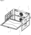
Figure 1 - is the sideways perspective view of the oven. -
Figure 2 - is the cross-sectional perspective view of the oven. -
Figure 3 - is the cross-sectional view of an embodiment of the present invention. -
Figure 4 - is the cross-sectional view of another embodiment of the present invention. -
Figure 5 - is the cross-sectional view of yet another embodiment of the present invention. -
Figure 6 - is the cross-sectional view of another embodiment of the present invention. -
Figure 7 - is the cross-sectional view of yet another embodiment of the present invention. - The elements illustrated in the figures are numbered as follows:
- 1. Oven
- 2. Cooking chamber
- 3. Body
- 4. Fan protection plate
- 5. Separator
- 6. Upper compartment
- 7. Lower compartment
- 8. Wall
- 9. Arm
- 10. First fan
- 11. Second fan
- 12. First air hole
- 13. Second air hole
- 14. Sealing member
- The oven (1) comprises a body (3); a cooking chamber (2) which is disposed in the body (3) and wherein the cooking process is performed; a fan protection plate (4) which forms the rear wall of the cooking chamber (2); a separator (5) which divides the cooking chamber (2) into an upper compartment (6) and a lower compartment (7); a first fan (10) which is disposed at the level of the upper compartment (6) between the fan protection plate (4) and the body (3); at least one first air hole (12) which is provided on the fan protection plate (4) at the level of the first fan (10); a second fan (11) which is disposed at the level of the lower compartment (7) between the fan protection plate (4) and the body (3); at least one second air hole (13) which is provided on the fan protection plate (4) at the level of the second fan (11); and a wall (8) which extends between the fan protection plate (4) and the body (3), along the fan protection plate (4), and which separates the first fan (10) and the second fan (11) in an airtight manner (
Figure 1 andFigure 2 ). - Thus, since air passage from the lower compartment (7) to the upper compartment (6) and from the upper compartment (6) to the lower compartment (7) is prevented between the fan protection plate (4) and the rear wall of the body (3), the mixing of odors between the upper and lower compartments (6 and 7) is prevented during different cooking operations in the upper and lower compartments (6 and 7). Moreover, during the cooking process in each of the upper and lower compartments (6 and 7), heat transfer in the area between the fan protection plate (4) and the rear wall of the body (3) is minimized. Thus, the thermal effectiveness of the upper and lower compartments (6 and 7) is increased and energy losses are minimized. Moreover, by closing the gap between the fan protection plate (4) and the rear wall of the body (3), the air to be blown into the upper and lower compartments (6 and 7) by the first and second fans (10 and 11) during the cooking process in the upper and lower compartments (6 and 7) is prevented from passing from the lower compartment (7) to the upper compartment (6) or from the upper compartment (6) to the lower compartment (7) such that homogeneous cooking is ensured in the upper and lower compartments (6 and 7). Furthermore, since sealing is provided in the area between the fan protection plate (4) and the rear wall of the body (3), the mixing of upper and lower compartment (6 and 7) air is prevented, thus eliminating inefficiency and flow rate reduction.
- In the embodiment of the present invention, the wall (8) and the separator (5) are aligned on the same horizontal plane.
- In an embodiment of the present invention, the wall (8) placed between the fan protection plate (4) and the rear wall of the body (3) in order to prevent air passage between the upper and lower compartments (6 and 7) is a sheet metal profile. In this embodiment of the present invention, the wall (8) completely closes the gap between the fan protection plate (4) and the rear wall. Thus, homogeneous cooking is ensured in the upper and lower compartments (6 and 7) by preventing the air blown into the upper compartment (6) by the first fan (10) and into the lower compartment (7) by the second fan (11) from passing between the upper and lower compartments (6 and 7).
- In another embodiment of the present invention, the wall (8) has a hollow quadrangular profile. In this embodiment of the present invention, one short edge of the wall (8) contacts the rear surface of the fan protection plate (4), and the other short edge contacts the front surface of the rear wall of the body (3) (
Figure 3 ). In the preferred embodiment of the present invention, the inside of the wall (8) in the form of a quadrangular profile is filled with sealing material. Thus, air tightness is ensured between the upper compartment (6) and the lower compartment (7) and thermal conduction is minimized. Preferably, insulation materials with low thermal conductivity coefficients such as glass wool, rock wool, stone wool and ceramic wool are used as sealing materials (Figure 4 ). - In another embodiment of the present invention, the oven (1) comprises a "U" shaped wall (8), the open end of which contacts the rear surface of the fan protection plate (4). When the wall (8) is mounted in place, the open end is closed with the fan protection plate (4), thus creating a closed volume. In this embodiment, the open end of the wall (8) is closed with the "U" shaped recess of the fan protection plate (4). Thus, by extending the path for the passage of air, the pressure is increased and air leakage is minimized (
Figure 7 ). - In another embodiment of the present invention, the oven (1) comprises two arms (9) which extend from the upper and lower surfaces of the wall (8) to bear against the rear surface of the fan protection plate (4). Thus, the wall (8) is joined with the fan protection plate (4) by means of the arms (9), creating a closed volume. In this embodiment of the present invention, the oven (1) comprises a sealing member (14) which is disposed between the arms (9) and the fan protection plate (4) in order to ensure complete sealing on the surfaces of the arms (9) in contact with the rear surface of the fan protection plate (4) (
Figure 5 and Figure 6 ). - By means of the present invention, since air passage from the lower compartment (7) to the upper compartment (6) and from the upper compartment (6) to the lower compartment (7) is prevented between the fan protection plate (4) and the rear wall of the body (3), the mixing of odors between the upper and lower compartments (6 and 7) is prevented during different cooking operations in the upper and lower compartments (6 and 7). Moreover, during the cooking process in each of the upper and lower compartments (6 and 7), heat transfer in the area between the fan protection plate (4) and the rear wall of the body (3) is minimized. Thus, the thermal effectiveness of the upper and lower compartments (6 and 7) is increased and energy losses are minimized. In addition, the problem of not manufacturing the fan protection plate (4) by the deep drawing method and the problem of not using enamel in the middle part of the fan protection plate (4) due to the coating depth are eliminated.
Claims (8)
- An oven (1) comprising a body (3); a cooking chamber (2) which is disposed in the body (3) and wherein the cooking process is performed; a fan protection plate (4) which forms the rear wall of the cooking chamber (2); a separator (5) which divides the cooking chamber (2) into an upper compartment (6) and a lower compartment (7); a first fan (10) which is disposed at the level of the upper compartment (6) between the fan protection plate (4) and the body (3); at least one first air hole (12) which is provided on the fan protection plate (4) at the level of the first fan (10); a second fan (11) which is disposed at the level of the lower compartment (7) between the fan protection plate (4) and the body (3); and at least one second air hole (13) which is provided on the fan protection plate (4) at the level of the second fan (11); characterized by a wall (8) which extends between the fan protection plate (4) and the body (3), along the fan protection plate (4), and which separates the first fan (10) and the second fan (11) in an airtight manner.
- An oven (1) as in Claim 1, characterized by the wall (8) which is located on the same horizontal plate as the separator (5).
- An oven (1) as in Claim 1, characterized by the wall (8) manufactured from sheet metal profile, placed between the fan protection plate (4) and the rear wall of the body (3) in order to prevent air passage between the upper and lower compartments (6 and 7).
- An oven (1) as in Claim 3, characterized by the wall (8) which has a hollow quadrangular profile.
- An oven (1) as in Claim 3 or 4, characterized by the wall (8) which has sealing material therein.
- An oven (1) as in Claim 1, characterized by a "U" shaped wall (8), the open end of which contacts the rear surface of the fan protection plate (4).
- An oven (1) as in Claim 1, characterized by two arms (9) which extend from the upper and lower surfaces of the wall (8) to bear against the rear surface of the fan protection plate (4).
- An oven (1) as in Claim 7, characterized by a sealing member (14) which is disposed between the arms (9) and the fan protection plate (4) in order to ensure complete sealing on the surfaces of the arms (9) in contact with the rear surface of the fan protection plate (4).
Applications Claiming Priority (1)
| Application Number | Priority Date | Filing Date | Title |
|---|---|---|---|
| TR202217326 | 2022-11-16 |
Publications (2)
| Publication Number | Publication Date |
|---|---|
| EP4372285A1 true EP4372285A1 (en) | 2024-05-22 |
| EP4372285B1 EP4372285B1 (en) | 2025-10-08 |
Family
ID=88647643
Family Applications (1)
| Application Number | Title | Priority Date | Filing Date |
|---|---|---|---|
| EP23207205.8A Active EP4372285B1 (en) | 2022-11-16 | 2023-10-31 | An oven with two compartments |
Country Status (2)
| Country | Link |
|---|---|
| EP (1) | EP4372285B1 (en) |
| PL (1) | PL4372285T3 (en) |
Citations (6)
| Publication number | Priority date | Publication date | Assignee | Title |
|---|---|---|---|---|
| US20020060215A1 (en) | 2000-10-26 | 2002-05-23 | Riccardo Allera | Cooking oven |
| US7087863B1 (en) | 2005-06-08 | 2006-08-08 | Samsung Electronics Co., Ltd. | Oven |
| DE102009051740B3 (en) * | 2009-11-03 | 2011-09-01 | Debag Vertrieb Gmbh | Baking device for preparing baked goods, has heating device and sensor attached to baking regions, and separating device selectively inserted between baking regions and thermally and fluidically separating baking atmospheres from each other |
| WO2013050546A1 (en) | 2011-10-06 | 2013-04-11 | Arcelik Anonim Sirketi | An oven with increased cooking efficiency |
| KR20150118860A (en) * | 2014-04-15 | 2015-10-23 | 삼성전자주식회사 | Oven |
| US20170146247A1 (en) * | 2014-07-22 | 2017-05-25 | Samsung Electronics Co., Ltd. | Oven |
-
2023
- 2023-10-31 EP EP23207205.8A patent/EP4372285B1/en active Active
- 2023-10-31 PL PL23207205.8T patent/PL4372285T3/en unknown
Patent Citations (6)
| Publication number | Priority date | Publication date | Assignee | Title |
|---|---|---|---|---|
| US20020060215A1 (en) | 2000-10-26 | 2002-05-23 | Riccardo Allera | Cooking oven |
| US7087863B1 (en) | 2005-06-08 | 2006-08-08 | Samsung Electronics Co., Ltd. | Oven |
| DE102009051740B3 (en) * | 2009-11-03 | 2011-09-01 | Debag Vertrieb Gmbh | Baking device for preparing baked goods, has heating device and sensor attached to baking regions, and separating device selectively inserted between baking regions and thermally and fluidically separating baking atmospheres from each other |
| WO2013050546A1 (en) | 2011-10-06 | 2013-04-11 | Arcelik Anonim Sirketi | An oven with increased cooking efficiency |
| KR20150118860A (en) * | 2014-04-15 | 2015-10-23 | 삼성전자주식회사 | Oven |
| US20170146247A1 (en) * | 2014-07-22 | 2017-05-25 | Samsung Electronics Co., Ltd. | Oven |
Also Published As
| Publication number | Publication date |
|---|---|
| EP4372285B1 (en) | 2025-10-08 |
| PL4372285T3 (en) | 2026-02-23 |
Similar Documents
| Publication | Publication Date | Title |
|---|---|---|
| US7784457B2 (en) | Oven | |
| EP1731843B1 (en) | Oven | |
| EP3745030B1 (en) | Cooking appliance | |
| RU2312274C2 (en) | Stove for cooking | |
| KR100628081B1 (en) | Electric oven range | |
| EP3940296B1 (en) | Cooking appliance | |
| EP3412975B1 (en) | Cooking appliance | |
| CN112902233B (en) | Cooking equipment and integrated kitchen | |
| CN221153831U (en) | Cooking all-in-one machine with door body heat dissipation function | |
| EP4372285B1 (en) | An oven with two compartments | |
| WO2007015215A2 (en) | A cooking device | |
| EP3645945B1 (en) | Improved gas cooker and method of operation of such gas cooker | |
| KR20060127690A (en) | Electric oven | |
| TR2022017326A2 (en) | A TWO SECTION OVEN | |
| CN213237614U (en) | Combined cooking machine with cooking stove | |
| KR100790391B1 (en) | Electric oven range | |
| KR100397254B1 (en) | A front exhaust structure of gas oven range | |
| KR200343492Y1 (en) | Structure for exhausting and cooling in oven | |
| JP2006296237A (en) | Electric heating pizza oven | |
| CN220551967U (en) | Exhaust assembly for integrated kitchen range and integrated kitchen range | |
| CN223881047U (en) | Door body assembly and cooking equipment | |
| EP1260771A1 (en) | Cooking oven with anti-condensation ventilation apertures | |
| EP4001776B1 (en) | Cooking appliance having a flue | |
| EP4675180A1 (en) | Device for thermal insulation and ventilation of a unit, preferably a kitchen unit, and kitchen unit comprising same | |
| KR100676137B1 (en) | Electric oven |
Legal Events
| Date | Code | Title | Description |
|---|---|---|---|
| PUAI | Public reference made under article 153(3) epc to a published international application that has entered the european phase |
Free format text: ORIGINAL CODE: 0009012 |
|
| STAA | Information on the status of an ep patent application or granted ep patent |
Free format text: STATUS: REQUEST FOR EXAMINATION WAS MADE |
|
| 17P | Request for examination filed |
Effective date: 20231101 |
|
| AK | Designated contracting states |
Kind code of ref document: A1 Designated state(s): AL AT BE BG CH CY CZ DE DK EE ES FI FR GB GR HR HU IE IS IT LI LT LU LV MC ME MK MT NL NO PL PT RO RS SE SI SK SM TR |
|
| STAA | Information on the status of an ep patent application or granted ep patent |
Free format text: STATUS: EXAMINATION IS IN PROGRESS |
|
| 17Q | First examination report despatched |
Effective date: 20250121 |
|
| GRAP | Despatch of communication of intention to grant a patent |
Free format text: ORIGINAL CODE: EPIDOSNIGR1 |
|
| STAA | Information on the status of an ep patent application or granted ep patent |
Free format text: STATUS: GRANT OF PATENT IS INTENDED |
|
| RIC1 | Information provided on ipc code assigned before grant |
Ipc: F24C 15/00 20060101AFI20250612BHEP Ipc: F24C 15/32 20060101ALI20250612BHEP Ipc: F24C 15/08 20060101ALN20250612BHEP |
|
| INTG | Intention to grant announced |
Effective date: 20250624 |
|
| RIC1 | Information provided on ipc code assigned before grant |
Ipc: F24C 15/00 20060101AFI20250616BHEP Ipc: F24C 15/32 20060101ALI20250616BHEP Ipc: F24C 15/08 20060101ALN20250616BHEP |
|
| GRAS | Grant fee paid |
Free format text: ORIGINAL CODE: EPIDOSNIGR3 |
|
| GRAA | (expected) grant |
Free format text: ORIGINAL CODE: 0009210 |
|
| STAA | Information on the status of an ep patent application or granted ep patent |
Free format text: STATUS: THE PATENT HAS BEEN GRANTED |
|
| RIN1 | Information on inventor provided before grant (corrected) |
Inventor name: UTE, MEHMET BATUHAN Inventor name: CIBARLI, YIGIT EKIN Inventor name: ONAL, MUSTAFA Inventor name: KARAER, EROL Inventor name: DEMIRBAG, ALI |
|
| AK | Designated contracting states |
Kind code of ref document: B1 Designated state(s): AL AT BE BG CH CY CZ DE DK EE ES FI FR GB GR HR HU IE IS IT LI LT LU LV MC ME MK MT NL NO PL PT RO RS SE SI SK SM TR |
|
| REG | Reference to a national code |
Ref country code: GB Ref legal event code: FG4D Ref country code: CH Ref legal event code: F10 Free format text: ST27 STATUS EVENT CODE: U-0-0-F10-F00 (AS PROVIDED BY THE NATIONAL OFFICE) Effective date: 20251008 |
|
| REG | Reference to a national code |
Ref country code: DE Ref legal event code: R096 Ref document number: 602023007298 Country of ref document: DE |
|
| REG | Reference to a national code |
Ref country code: IE Ref legal event code: FG4D |
|
| REG | Reference to a national code |
Ref country code: NL Ref legal event code: MP Effective date: 20251008 |
|
| REG | Reference to a national code |
Ref country code: AT Ref legal event code: MK05 Ref document number: 1845087 Country of ref document: AT Kind code of ref document: T Effective date: 20251008 |
|
| PG25 | Lapsed in a contracting state [announced via postgrant information from national office to epo] |
Ref country code: NL Free format text: LAPSE BECAUSE OF FAILURE TO SUBMIT A TRANSLATION OF THE DESCRIPTION OR TO PAY THE FEE WITHIN THE PRESCRIBED TIME-LIMIT Effective date: 20251008 |
|
| PG25 | Lapsed in a contracting state [announced via postgrant information from national office to epo] |
Ref country code: ES Free format text: LAPSE BECAUSE OF FAILURE TO SUBMIT A TRANSLATION OF THE DESCRIPTION OR TO PAY THE FEE WITHIN THE PRESCRIBED TIME-LIMIT Effective date: 20251008 |
|
| REG | Reference to a national code |
Ref country code: LT Ref legal event code: MG9D |
|
| PG25 | Lapsed in a contracting state [announced via postgrant information from national office to epo] |
Ref country code: NO Free format text: LAPSE BECAUSE OF FAILURE TO SUBMIT A TRANSLATION OF THE DESCRIPTION OR TO PAY THE FEE WITHIN THE PRESCRIBED TIME-LIMIT Effective date: 20260108 |
|
| PG25 | Lapsed in a contracting state [announced via postgrant information from national office to epo] |
Ref country code: AT Free format text: LAPSE BECAUSE OF FAILURE TO SUBMIT A TRANSLATION OF THE DESCRIPTION OR TO PAY THE FEE WITHIN THE PRESCRIBED TIME-LIMIT Effective date: 20251008 Ref country code: FI Free format text: LAPSE BECAUSE OF FAILURE TO SUBMIT A TRANSLATION OF THE DESCRIPTION OR TO PAY THE FEE WITHIN THE PRESCRIBED TIME-LIMIT Effective date: 20251008 Ref country code: HR Free format text: LAPSE BECAUSE OF FAILURE TO SUBMIT A TRANSLATION OF THE DESCRIPTION OR TO PAY THE FEE WITHIN THE PRESCRIBED TIME-LIMIT Effective date: 20251008 |
|
| PG25 | Lapsed in a contracting state [announced via postgrant information from national office to epo] |
Ref country code: RS Free format text: LAPSE BECAUSE OF FAILURE TO SUBMIT A TRANSLATION OF THE DESCRIPTION OR TO PAY THE FEE WITHIN THE PRESCRIBED TIME-LIMIT Effective date: 20260108 |
|
| PG25 | Lapsed in a contracting state [announced via postgrant information from national office to epo] |
Ref country code: IS Free format text: LAPSE BECAUSE OF FAILURE TO SUBMIT A TRANSLATION OF THE DESCRIPTION OR TO PAY THE FEE WITHIN THE PRESCRIBED TIME-LIMIT Effective date: 20260208 |
|
| PGFP | Annual fee paid to national office [announced via postgrant information from national office to epo] |
Ref country code: TR Payment date: 20260108 Year of fee payment: 3 |
|
| PG25 | Lapsed in a contracting state [announced via postgrant information from national office to epo] |
Ref country code: PT Free format text: LAPSE BECAUSE OF FAILURE TO SUBMIT A TRANSLATION OF THE DESCRIPTION OR TO PAY THE FEE WITHIN THE PRESCRIBED TIME-LIMIT Effective date: 20260209 |
|
| PGFP | Annual fee paid to national office [announced via postgrant information from national office to epo] |
Ref country code: PL Payment date: 20260313 Year of fee payment: 3 |
|
| PG25 | Lapsed in a contracting state [announced via postgrant information from national office to epo] |
Ref country code: LV Free format text: LAPSE BECAUSE OF FAILURE TO SUBMIT A TRANSLATION OF THE DESCRIPTION OR TO PAY THE FEE WITHIN THE PRESCRIBED TIME-LIMIT Effective date: 20251008 |
|
| PG25 | Lapsed in a contracting state [announced via postgrant information from national office to epo] |
Ref country code: BG Free format text: LAPSE BECAUSE OF FAILURE TO SUBMIT A TRANSLATION OF THE DESCRIPTION OR TO PAY THE FEE WITHIN THE PRESCRIBED TIME-LIMIT Effective date: 20251008 |
|
| REG | Reference to a national code |
Ref country code: DE Ref legal event code: R119 Ref document number: 602023007298 Country of ref document: DE |
|
| PG25 | Lapsed in a contracting state [announced via postgrant information from national office to epo] |
Ref country code: RO Free format text: LAPSE BECAUSE OF FAILURE TO SUBMIT A TRANSLATION OF THE DESCRIPTION OR TO PAY THE FEE WITHIN THE PRESCRIBED TIME-LIMIT Effective date: 20251008 |
|
| PG25 | Lapsed in a contracting state [announced via postgrant information from national office to epo] |
Ref country code: LU Free format text: LAPSE BECAUSE OF NON-PAYMENT OF DUE FEES Effective date: 20251031 |
|
| REG | Reference to a national code |
Ref country code: BE Ref legal event code: MM Effective date: 20251031 |
|
| PG25 | Lapsed in a contracting state [announced via postgrant information from national office to epo] |
Ref country code: LT Free format text: LAPSE BECAUSE OF FAILURE TO SUBMIT A TRANSLATION OF THE DESCRIPTION OR TO PAY THE FEE WITHIN THE PRESCRIBED TIME-LIMIT Effective date: 20251008 |
|
| PG25 | Lapsed in a contracting state [announced via postgrant information from national office to epo] |
Ref country code: SM Free format text: LAPSE BECAUSE OF FAILURE TO SUBMIT A TRANSLATION OF THE DESCRIPTION OR TO PAY THE FEE WITHIN THE PRESCRIBED TIME-LIMIT Effective date: 20251008 |
|
| PG25 | Lapsed in a contracting state [announced via postgrant information from national office to epo] |
Ref country code: MC Free format text: LAPSE BECAUSE OF FAILURE TO SUBMIT A TRANSLATION OF THE DESCRIPTION OR TO PAY THE FEE WITHIN THE PRESCRIBED TIME-LIMIT Effective date: 20251008 |
|
| PG25 | Lapsed in a contracting state [announced via postgrant information from national office to epo] |
Ref country code: DK Free format text: LAPSE BECAUSE OF FAILURE TO SUBMIT A TRANSLATION OF THE DESCRIPTION OR TO PAY THE FEE WITHIN THE PRESCRIBED TIME-LIMIT Effective date: 20251008 |
|
| PG25 | Lapsed in a contracting state [announced via postgrant information from national office to epo] |
Ref country code: IT Free format text: LAPSE BECAUSE OF FAILURE TO SUBMIT A TRANSLATION OF THE DESCRIPTION OR TO PAY THE FEE WITHIN THE PRESCRIBED TIME-LIMIT Effective date: 20251008 |
|
| PG25 | Lapsed in a contracting state [announced via postgrant information from national office to epo] |
Ref country code: DE Free format text: LAPSE BECAUSE OF NON-PAYMENT OF DUE FEES Effective date: 20260501 |
|
| PG25 | Lapsed in a contracting state [announced via postgrant information from national office to epo] |
Ref country code: BE Free format text: LAPSE BECAUSE OF NON-PAYMENT OF DUE FEES Effective date: 20251031 |
|
| PG25 | Lapsed in a contracting state [announced via postgrant information from national office to epo] |
Ref country code: EE Free format text: LAPSE BECAUSE OF FAILURE TO SUBMIT A TRANSLATION OF THE DESCRIPTION OR TO PAY THE FEE WITHIN THE PRESCRIBED TIME-LIMIT Effective date: 20251008 |
|
| PG25 | Lapsed in a contracting state [announced via postgrant information from national office to epo] |
Ref country code: CZ Free format text: LAPSE BECAUSE OF FAILURE TO SUBMIT A TRANSLATION OF THE DESCRIPTION OR TO PAY THE FEE WITHIN THE PRESCRIBED TIME-LIMIT Effective date: 20251008 |
|
| PG25 | Lapsed in a contracting state [announced via postgrant information from national office to epo] |
Ref country code: SK Free format text: LAPSE BECAUSE OF FAILURE TO SUBMIT A TRANSLATION OF THE DESCRIPTION OR TO PAY THE FEE WITHIN THE PRESCRIBED TIME-LIMIT Effective date: 20251008 |
|
| PG25 | Lapsed in a contracting state [announced via postgrant information from national office to epo] |
Ref country code: SE Free format text: LAPSE BECAUSE OF FAILURE TO SUBMIT A TRANSLATION OF THE DESCRIPTION OR TO PAY THE FEE WITHIN THE PRESCRIBED TIME-LIMIT Effective date: 20251008 |
|
| PLBE | No opposition filed within time limit |
Free format text: ORIGINAL CODE: 0009261 |
|
| STAA | Information on the status of an ep patent application or granted ep patent |
Free format text: STATUS: NO OPPOSITION FILED WITHIN TIME LIMIT |