EP4372133A1 - Yarn heater and false-twist texturing machine - Google Patents
Yarn heater and false-twist texturing machine Download PDFInfo
- Publication number
- EP4372133A1 EP4372133A1 EP23206665.4A EP23206665A EP4372133A1 EP 4372133 A1 EP4372133 A1 EP 4372133A1 EP 23206665 A EP23206665 A EP 23206665A EP 4372133 A1 EP4372133 A1 EP 4372133A1
- Authority
- EP
- European Patent Office
- Prior art keywords
- plate
- yarn
- members
- spaces
- heating unit
- Prior art date
- Legal status (The legal status is an assumption and is not a legal conclusion. Google has not performed a legal analysis and makes no representation as to the accuracy of the status listed.)
- Granted
Links
Images





Classifications
-
- D—TEXTILES; PAPER
- D02—YARNS; MECHANICAL FINISHING OF YARNS OR ROPES; WARPING OR BEAMING
- D02J—FINISHING OR DRESSING OF FILAMENTS, YARNS, THREADS, CORDS, ROPES OR THE LIKE
- D02J13/00—Heating or cooling the yarn, thread, cord, rope, or the like, not specific to any one of the processes provided for in this subclass
- D02J13/003—Heating or cooling the yarn, thread, cord, rope, or the like, not specific to any one of the processes provided for in this subclass by contact with at least one stationary surface, e.g. a plate
-
- D—TEXTILES; PAPER
- D02—YARNS; MECHANICAL FINISHING OF YARNS OR ROPES; WARPING OR BEAMING
- D02G—CRIMPING OR CURLING FIBRES, FILAMENTS, THREADS, OR YARNS; YARNS OR THREADS
- D02G1/00—Producing crimped or curled fibres, filaments, yarns, or threads, giving them latent characteristics
- D02G1/02—Producing crimped or curled fibres, filaments, yarns, or threads, giving them latent characteristics by twisting, fixing the twist and backtwisting, i.e. by imparting false twist
- D02G1/0206—Producing crimped or curled fibres, filaments, yarns, or threads, giving them latent characteristics by twisting, fixing the twist and backtwisting, i.e. by imparting false twist by false-twisting
- D02G1/0266—Producing crimped or curled fibres, filaments, yarns, or threads, giving them latent characteristics by twisting, fixing the twist and backtwisting, i.e. by imparting false twist by false-twisting false-twisting machines
-
- D—TEXTILES; PAPER
- D01—NATURAL OR MAN-MADE THREADS OR FIBRES; SPINNING
- D01H—SPINNING OR TWISTING
- D01H13/00—Other common constructional features, details or accessories
- D01H13/28—Heating or cooling arrangements for yarns
-
- H—ELECTRICITY
- H05—ELECTRIC TECHNIQUES NOT OTHERWISE PROVIDED FOR
- H05B—ELECTRIC HEATING; ELECTRIC LIGHT SOURCES NOT OTHERWISE PROVIDED FOR; CIRCUIT ARRANGEMENTS FOR ELECTRIC LIGHT SOURCES, IN GENERAL
- H05B3/00—Ohmic-resistance heating
- H05B3/40—Heating elements having the shape of rods or tubes
- H05B3/42—Heating elements having the shape of rods or tubes non-flexible
Definitions
- the present invention relates to a yarn heater configured to heat a yarn and a false-twist texturing machine including this yarn heater.
- a known yarn heater is configured to heat a running yarn formed of synthetic fibers in a processor configured to perform various processes such as yarn combining and false twisting.
- a false-twist texturing machine of Patent Literature 1 Japanese Unexamined Patent Publication No. 2016-056494 ) is provided with a primary heating unit (yarn heater) including a box (heat retaining box), a heater (heating unit) housed in a housing space of the box, and a heat insulating material provided to fill a gap in the housing space housing the heater.
- the heater is provided with a yarn running groove, and a yarn running in the yarn running groove is heated.
- An object of the present invention is to provide a yarn heater that reduces power consumption and a false-twist texturing machine including this yarn heater, without increasing the size of the heater.
- a yarn heater is provided with a yarn running path in which a yarn runs.
- This yarn heater includes: a heating unit which extends along a predetermined direction and which is configured to heat the yarn running in the yarn running path extending in the predetermined direction; at least three plate members which oppose each other at intervals and are aligned in a direction away from the heating unit on a virtual plane which is orthogonal to the predetermined direction and which intersects with the heating unit; and a sealing member sealing at least one of at least two between-plate spaces at at least a part of an end portion of the at least one of the at least two between-plate spaces each of which is provided between opposing two of the at least three plate members, air layers provided at the at least two between-plate spaces being aligned in the direction away from the heating unit on the virtual plane.
- the end portion of the at least one of the at least two between-plate spaces each of which is provided between opposing two of the at least three plate members is a boundary of a between-plate space and does not overlap the two opposing plate members forming the between-plate space.
- heat radiation from the heating unit to the outside is suppressed by the air layers aligned in the direction away from the heating unit on the virtual plane. Because each air layer has a relatively-low heat conductivity, adequate performance of heat insulation is achieved even when the thickness of the air layer is small. Because the at least one between-plate space is sealed at at least a part of its end portion by the sealing member, air is suppressed from going inside and outside of the at least one between-plate space. This suppresses the occurrence of convection in the air layer. It is therefore possible to suppress the occurrence of heat transfer between two adjacent plate members forming a between-plate space, and to further improve the performance of heat insulation by an air layer. This reduces power consumption without increasing the size of the heater.
- the yarn heater of the first aspect is arranged such that the at least one of the at least two between-plate spaces is sealed.
- the at least one between-plate space is sealed, air is reliably suppressed from going inside and outside of the at least one between-plate space. It is therefore possible to further improve the performance of heat insulation by the air layer.
- the yarn heater of the first or second aspect is arranged such that the at least three plate members extend along the predetermined direction.
- the sealing member includes first sealing members which are formed of heat insulating materials and which seal the at least one of the at least two between-plate spaces at both end portions of the at least one of the at least two between-plate spaces in the predetermined direction.
- the first sealing members seal the at least one between-plate space at both its end portions in the predetermined direction.
- air is suppressed from going in and out of the at least one between-plate space through these end portions.
- the first sealing members sealing the at least one between-plate space at both its end portions in the predetermined direction are formed of heat insulating materials, heat transfer via the first sealing members is suppressed between adjacent plate members. It is therefore possible to further improve the performance of heat insulation by the air layer.
- the yarn heater of the third aspect is arranged such that the density of each of the first sealing members is 80 kg/m 3 or more.
- each first sealing member has a high density, air is further reliably suppressed from going inside and outside of each between-plate space through the first sealing member. It is therefore possible to further reliably seal the between-plate space.
- the yarn heater of any one of the first to fourth aspects includes a spacer member provided in each of the at least two between-plate spaces.
- the air layer is provided at the between-plate space.
- the spacer member is provided in the between-plate space so that the thickness of the between-plate space is even. It is therefore possible to suppress the occurrence of convection in the air layer, and to further improve the performance of heat insulation by the air layer.
- the yarn heater of the fifth aspect is arranged such that spacer members which are respectively provided in two adjacent between-plate spaces are provided at different positions in the predetermined direction.
- the yarn heater of the fifth or sixth aspect is arranged such that the two of the at least three plate members form the each of the at least two between-plate spaces, one end portions of the two of the at least three plate members are provided on one side in an orthogonal direction orthogonal to the predetermined direction and bent so as to form bent portions sealing the at least one of the at least two between-plate spaces at one end portion of the at least one of the at least two between-plate spaces on the one side in the orthogonal direction, and the bent portions seal one of the two adjacent between-plate spaces and are provided at different positions in the orthogonal direction from one of the spacer members which is provided at the other of the two adjacent between-plate spaces.
- each between-plate space is sealed by the bent portions which are parts of two plate members. Furthermore, heat transfer via the bent portions and the spacer members is suppressed between adjacent plate members. It is therefore possible to further improve the performance of heat insulation by each air layer.
- the yarn heater of the seventh aspect is arranged such that the two of the at least three plate members form the each of the at least two between-plate members, and the bent portions function as spacers that maintain a gap between the two of the at least three plate members.
- the bent portions cause the thickness of each between-plate space to be even.
- the yarn heater of the seventh or eighth aspect is arranged such that, when adjacent three of the at least three plate members are a first plate member, a second plate member, and a third plate member, one of the at least two between-plate spaces is provided between the first plate member and the second plate member and sealed at one end portion of the one of the at least two between-plate spaces on the one side in the orthogonal direction by the bent portions formed by bending one end portion of the first plate member and one end portion of the second plate member on the one side in the orthogonal direction.
- the sealing member includes a second sealing member formed of a heat insulating material, another of the at least two between-plate spaces is provided between the second plate member and the third plate member, and the second sealing member seals the another of the at least two between-plate spaces at one end portion of the another of the at least two between-plate spaces on the one side in the orthogonal direction.
- the bent portions sealing the between-plate spaces continuously transfer heat between plate members.
- the second sealing member formed of the heat insulating material seals a between-plate space provided between the second and third plate members. It is therefore possible to suppress heat transferred between the first and second plate members via the bent portions of the plate members from being transferred to the third plate member. It is therefore possible to further improve the performance of heat insulation by each air layer while maintaining the airtightness of each between-plate space.
- the yarn heater of the ninth aspect is arranged such that, when one of three adjacent between-plate spaces is closest to the heating unit, another of the three adjacent between-plate spaces is farthest from the heating unit, and each of the one and the another of the three adjacent between-plate spaces is sealed by the bent portions, the bent portions sealing the each of the one and the another of the three adjacent between-plate spaces are provided at different positions in the orthogonal direction.
- the yarn heater of the ninth or tenth aspect includes a covering member which is formed of a heat insulating material and which covers surfaces of the bent portions on a side opposite to one of at least one first between-plate space which is included in the at least two between-plate spaces and which is sealed by the bent portions, the bent portions sealing the one of the at least one first between-plate space at least, and the one of the at least one first between-plate space being closest to the heating unit.
- the covering member suppresses heat radiation from the bent portions. Especially, it is possible to reliably suppress heat radiation from a bent portion of a plate member provided in the vicinity of the heating unit and whose temperature is high.
- the yarn heater of the eleventh aspect is arranged such that the second sealing member additionally functions as the covering member.
- the structure of the yarn heater is simplified as compared to the case where the covering member is different from the second sealing member.
- the yarn heater of the twelfth aspect of the invention is arranged such that second between-plate spaces are included in the at least two between-plate spaces and not sealed by the bent portions, the bent portions regard all of first between-plate spaces, and the second sealing member seals all of the second between-plate spaces at one end portions of the second between-plate spaces on the one side in the orthogonal direction and covers the surfaces of the bent portions on a side opposite to the all of the first between-plate spaces.
- the performance of heat insulation by air layers is further improved while maintaining the airtightness of all between-plate spaces only by the second sealing member.
- the yarn heater of the twelfth or thirteenth aspect is arranged such that the at least three plate members cover the entire heating unit in the orthogonal direction, the one of the first between-plate spaces is closest to the heating unit and sealed by a first bent portion which is included in the bent portions, the first bent portion is closer to the heating unit in the orthogonal direction than a second bent portion which is included in the bent portions and which seals another of the first between-plate spaces, and in the second sealing member, the thickness of a part covering the first bent portion is larger than the thickness of a part covering the second bent portion in the orthogonal direction.
- the yarn heater of any one of the ninth to fourteenth aspects includes a connecting member connecting adjacent two of the at least three plate members to each other.
- the first plate member and the second plate member are connected to each other by the bent portions
- the second plate member and the third plate member are connected to each other by the connecting member at an end portion of the second plate member and an end portion of the third plate member on the other side opposite to the one side in the orthogonal direction.
- the bent portions fixing the first and second plate members to each other maintain the layer thickness of an air layer provided between the first and second plate members.
- the connecting member fixing the second and third plate members to each other maintain the layer thickness of an air layer provided between the second and third plate members.
- the junction (where the bent portions are formed) between the first and second plate members is separated from the junction (where the second and third plate members are connected by the connecting member) between the second and third plate members in the orthogonal direction. It is therefore possible to suppress heat transfer between the first and third plate members via the two junctions, and to further improve the performance of heat insulation by air layers.
- the yarn heater of any one of the first to eighth aspects is arranged such that the sealing member includes a second sealing member which is formed of a heat insulating material and which seals the at least one of the at least two between-plate spaces at one end portion of the at least one of the at least two between-plate spaces on one side in an orthogonal direction orthogonal to the predetermined direction.
- the sealing member includes a second sealing member which is formed of a heat insulating material and which seals the at least one of the at least two between-plate spaces at one end portion of the at least one of the at least two between-plate spaces on one side in an orthogonal direction orthogonal to the predetermined direction.
- the second sealing member seals at least one between-plate space at its one end portion on the one side in the orthogonal direction. As a result, air is suppressed from going in and out of the between-plate space through this end portion. Because the second sealing member is formed of the heat insulating material, heat transfer via the second sealing member is suppressed between adjacent plate members. It is therefore possible to further improve the performance of heat insulation by each air layer.
- the yarn heater of any one of the ninth to sixteenth aspects is arranged such that the density of the second sealing member is 80 kg/m 3 or more.
- the second sealing member has a high density, air is further reliably suppressed from going inside and outside of each between-plate space through the second sealing member. It is therefore possible to further reliably seal each between-plate space.
- the yarn heater of any one of the first to seventeenth aspects is arranged such that the layer thickness of each of the air layers is 5 mm or more and less than 15 mm.
- the thickness of the air layer is arranged to be able to suppress (i) the occurrence of convection in the air layer and (ii) the contact between the adjacent plate members. It is therefore possible to further improve the performance of heat insulation by the air layer.
- the yarn heater of any one of the first to eighteenth aspects includes a heat insulation member provided between one of the at least three plate members and the heating unit, the one of the at least three plate members being closest to the heating unit.
- a bolt, etc. for fixation of each member forming the heating unit is exposed to a surface of the heating unit so that the surface of the heating unit is not even. It is therefore difficult to provide, between the surface of the heating unit and a plate member, an air layer whose thickness is even and whose performance of heat insulation is high. According to this aspect, the heat insulation member is provided between the heating unit and the plate member. It is therefore possible to further suppress heat radiation from the heating unit to the outside.
- the yarn heater of any one of the first to nineteenth aspects is arranged such that the yarn running path is at least partially defined in the heating unit and is a yarn running groove which is open in an open direction orthogonal to the predetermined direction.
- the yarn is efficiently heated.
- the yarn heater of the twentieth aspect is arranged such that the at least three plate members are provided not to oppose an open end of the yarn running groove in the open direction.
- a space for allowing the yarn to pass therethrough at the time of insertion of the yarn into the yarn running groove is provided to oppose the open end of the yarn running groove.
- the yarn heater of the 21st aspect is arranged such that each of the at least three plate members extends along the predetermined direction and forms a groove which is open in the open direction, and the at least three plate members are nested so that the innermost one of the at least three plate members surrounds the heating unit.
- the yarn heater of any one of the first to 22nd aspects is arranged such that the one of the at least two between-plate spaces is closest to the heating unit, the two of the at least three plate members form the one of the between-plate spaces, one of opposing surfaces of the two of the at least three plate members is closer to the heating unit, and at least the one of the opposing surfaces of the two of the at least three plate members is a surface with a mirror finish.
- At least one of the opposing surfaces of two plate members is a surface with a mirror finish and suppresses radiant heat from the heating unit. It is therefore possible to suppress heat transfer due to radiation, and to further reduce power consumption.
- a surface of a plate member defining a between-plate space closest to the heating unit is a surface with a mirror-finish. It is therefore possible to suppress cost increase while suppressing radiant heat from the heating unit most effectively.
- dirt tends to be conspicuous on the mirror-finished surfaces.
- the surface of the plate member defining the above-described between-plate space cannot be seen from the outside and is the mirror-finished surface, the dirt on the mirror-finished surface is unlikely to be noticed.
- a false-twist texturing machine is configured to false-twist a yarn and includes the yarn heater according to any one of the first to 23rd aspects.
- a vertical direction to the sheet of FIG. 1 is defined as a base longitudinal direction, and a left-right direction to the sheet is defined as a base width direction.
- a direction orthogonal to both the base longitudinal direction and the base width direction is defined as an up-down direction in which the gravity acts.
- the base longitudinal direction and the base width direction are substantially in parallel to the horizontal direction.
- the false-twist texturing machine 1 is able to perform false twisting of yarns Y (i.e., to false-twist the yarns Y) made of synthetic fibers such as nylon (polyamide fibers) and polyester.
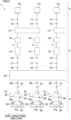
- the false-twist texturing machine 1 includes a yarn supplying part 2 for supplying the yarns Y, a processing part 3 configured to false-twist the yarns Y supplied from the yarn supplying part 2, and a winding part 4 configured to wind the yarns Y processed by the processing part 3 onto winding bobbins Bw.
- Components of the yarn supplying part 2, the processing part 3, and the winding part 4 are aligned to form plural lines in the base longitudinal direction (see FIG. 2 ).
- the base longitudinal direction is a direction orthogonal to a running plane (the sheet of FIG. 1 ) of the yarns Y, which is formed of the yarn paths extending from the yarn supplying part 2 to the winding part 4 via the processing part 3.
- the yarn supplying part 2 includes a creel stand 5 retaining plural yarn supply packages Ps.
- the yarn supplying part 2 is configured to supply the plural yarns Y to the processing part 3.
- the processing part 3 is configured to false-twist the yarns Y supplied from the yarn supply packages Ps.
- the following members are placed in this order from the upstream side in a yarn running direction: each first feed roller 11; each twist-stopping guide 12; each first heater 13 (equivalent to a yarn heater of the present invention); each cooler 14; each false-twisting device 15; each second feed roller 16; each interlacing device 17; each third feed roller 18; a second heater 19; and each fourth feed roller 20.
- the winding part 4 includes plural winding devices 21. Each winding device 21 is configured to wind a yarn Y false-twisted by the processing part 3 onto a winding bobbin Bw, so as to form a wound package Pw.
- the false-twist texturing machine 1 includes a main base 8 and a winding base 9 that are spaced apart from each other in the base width direction.
- the main base 8 and the winding base 9 extend to substantially the same length in the base longitudinal direction.
- the main base 8 and the winding base 9 oppose each other in the base width direction.
- An upper part of the main base 8 is connected to an upper part of the winding base 9 by a supporting frame 10.
- Each device forming the processing part 3 is mainly attached to the main base 8 or the supporting frame 10.
- Each device forming the winding part 4 is attached to the winding base 9.
- the main base 8, the winding base 9, and the supporting frame 10 form a working space A where an operator performs an operation such as yarn threading to each device.
- the yarn paths are formed so that the yarns Y mainly run around the working space A.
- the false-twist texturing machine 1 includes units termed spans each of which includes a pair of the main base 8 and the winding base 9 provided to oppose each other.
- processing units which are also termed spindles
- yarn paths are formed to pass the devices constituting the processing part 3 are aligned in the base longitudinal direction.
- plural yarns Y running while being aligned in the base longitudinal direction can be simultaneously false-twisted.
- the spans are placed in a left-right symmetrical manner to the sheet, with a center line C in the base width direction of the main base 8 set as a symmetry axis.
- the main base 8 is shared between the left span and the right span.
- Each first feed roller 11 is configured to unwind a yarn Y from a yarn supply package Ps attached to the yarn supplying part 2, and to feed the yarn Y to a first heater 13. As shown in FIG. 2 , for example, the first feed roller 11 is configured to feed one yarn Y to the first heater 13. The first feed roller 11 may be able to feed adjacent yarns Y to the downstream side in the yarn running direction.
- Each twist-stopping guide 12 is provided to prevent the twist of a yarn Y formed by a false-twisting device 15 from being propagated to the upstream side of the twist-stopping guide 12 in the yarn running direction.
- Each first heater 13 is configured to heat yarns Y supplied from some first feed rollers 11 to a predetermined processing temperature. As shown in FIG. 2 , for example, the first heater 13 is able to heat two yarns Y. The first heater 13 will be detailed later.
- Each cooler 14 is configured to cool a yarn Y heated by a first heater 13. As shown in FIG. 2 , for example, the cooler 14 is configured to cool one yarn Y. The cooler 14 may be able to simultaneously cool plural yarns Y.
- Each false-twisting device 15 is provided downstream of a cooler 14 in the yarn running direction.
- the false-twisting device 15 is configured to twist a yarn Y.
- the false-twisting device 15 is, e.g., a so-called disc-friction-type false-twisting device.
- the disclosure is not limited to this.
- Each second feed roller 16 is configured to feed a yarn Y processed by a false-twisting device 15 to an interlacing device 17.
- the conveyance speed of conveying the yarn Y by the second feed roller 16 is higher than the conveyance speed of conveying the yarn Y by each first feed roller 11. With this arrangement, the yarn Y is drawn and false-twisted between the first feed roller 11 and the second feed roller 16.
- Each interlacing device 17 is configured to interlace a yarn Y.
- the interlacing device 17 includes, e.g., a known interlace nozzle configured to interlace the yarn Y by means of an airflow.
- Each third feed roller 18 is configured to feed a yarn Y running on the downstream side of an interlacing device 17 in the yarn running direction, to the second heater 19. As shown in FIG. 2 , for example, the third feed roller 18 is configured to feed one yarn Y to the second heater 19. The third feed roller 18 may be able to feed adjacent yarns Y to the downstream side in the yarn running direction. The conveyance speed of conveying the yarn Y by the third feed roller 18 is lower than the conveyance speed of conveying the yarn Y by each second feed roller 16. The yarn Y is therefore relaxed between the second feed roller 16 and the third feed roller 18.
- the second heater 19 is configured to heat yarns Y fed from some third feed rollers 18.
- the second heater 19 extends along the vertical direction, and one second heater 19 is provided in one span.
- Each fourth feed roller 20 is configured to feed a yarn Y heated by the second heater 19 to a winding device 21. As shown in FIG. 2 , for example, the fourth feed roller 20 is able to feed one yarn Y to the winding device 21. The fourth feed roller 20 may be able to feed adjacent yarns Y to the downstream side in the yarn running direction. The conveyance speed of conveying the yarn Y by the fourth feed roller 20 is lower than the conveyance speed of conveying the yarn Y by each third feed roller 18. The yarn Y is therefore relaxed between the third feed roller 18 and the fourth feed roller 20.
- the yarn Y drawn between the first feed roller 11 and the second feed roller 16 is twisted by the false-twisting device 15.
- the twist formed by the false-twisting device 15 propagates to the twist-stopping guide 12, but does not propagate to the upstream side of the twist-stopping guide 12 in the yarn running direction.
- the yarn Y which is twisted and drawn is heated by the first heater 13 and thermally set. After that, the yarn Y is cooled by the cooler 14.
- the yarn Y is untwisted on the downstream side of the false-twisting device 15 in the yarn running direction.
- the yarn Y is maintained to be wavy in shape on account of the thermal setting described above (i.e., the crimp contraction of the yarn Y is maintained).
- the false-twisted yarn Y is interlaced by the interlacing device 17 while being relaxed between the second feed roller 16 and the third feed roller 18. After that, the yarn Y is guided toward the downstream side in the yarn running direction. Furthermore, the yarn Y is thermally processed by the second heater 19 while being relaxed between the third feed roller 18 and the fourth feed roller 20. Finally, the yarn Y fed from the fourth feed roller 20 is wound by the winding device 21.
- the winding part 4 includes plural winding devices 21. Each winding device 21 is able to wind a yarn Y onto one winding bobbin Bw.
- the winding device 21 includes a fulcrum guide 31, a traverse device 32, and a cradle 33.
- the fulcrum guide 31 is a guide functioning as a fulcrum when the yarn Y is traversed.
- the traverse device 32 is able to traverse the yarn Y by means of a traverse guide 34.
- the cradle 33 is configured to rotatably support the winding bobbin Bw.
- a contact roller 35 is provided in the vicinity of the cradle 33.
- the contact roller 35 is configured to make contact with a surface of a wound package Pw so as to apply a contact pressure to the surface of the wound package Pw.
- the yarn Y fed by the fourth feed roller 20 described above is wound onto the winding bobbin Bw by each winding device 21 so as to form the wound package Pw.
- FIG. 7 does not show a second sealing member 83, for the sake of convenience.
- FIG. 8 is used for explaining the thicknesses Ta1, Tb1, Ta2, and Tb2 described later, and may not show unnecessary reference numerals, etc.
- the first heater 13 extends in a predetermined extending direction (equivalent to a "predetermined direction" of the present invention) orthogonal to the base longitudinal direction.
- the extending direction is in parallel to the base width direction.
- the extending direction may be tilted with respect to the base width direction.
- the first heater 13 is provided with yarn running grooves 56 (see FIG. 5 ) extending along the extending direction. Each yarn running groove 56 is equivalent to a "yarn running path" of the present invention.
- the first heater 13 is configured to heat a yarn Y running from one side to the other side in the extending direction of each yarn running groove 56. In the present embodiment, the first heater 13 is able to heat two yarns Y (yarns Ya and Yb: see FIG. 5 ).
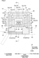
- the first heater 13 mainly includes a heating unit 50, heat insulating blocks 91, 92, and 93, a box 60, plate members 71, 72, 73, and 74.
- the heating unit 50 is provided with each yarn running groove 56 (56a, 56b) extending along the extending direction. Each yarn running groove 56 (56a, 56b) is open downward.
- the heating unit 50 is configured to heat each yarn Y (yarn Ya, Yb) running in the yarn running groove 56 (56a, 56b).
- the box 60 houses the heating unit 50 and the heat insulating blocks 91, 92, and 93.
- the plate members 71, 72, 73, and 74 are provided between the heating unit 50 and an inner wall surface of the box 60.
- the heating unit 50 mainly includes a heat source 51, two heating blocks 52 (52a and 52b) and two yarn contacted portions 54 (54a and 54b).
- the heat source 51 is, e.g., a sheathed heater. As shown in FIG. 6 , the heat source 51 extends along the extending direction.
- the heating blocks 52 and the yarn contacted portions 54 are heated by heat generated by the heat source 51.
- the heating blocks 52 and the yarn contacted portions 54 extend in the extending direction along the heat source 51.
- a bolt 59, etc. for fixation of each member forming the heating unit 50 is exposed to the surface of the heating unit 50.
- the heating block 52a and the yarn contacted portion 54a are members for heating the yarn Ya.
- the heating block 52b and the yarn contacted portion 54b are members for heating the yarn Yb.
- the members for heating the yarn Ya oppose the members for heating the yarn Yb over the heat source 51 in the base longitudinal direction.
- the heating block 52a is made of a metal material such as yellow copper having a high specific heat.
- the heating block 52a is provided to be in contact with the heat source 51.
- the heating block 52a is provided on one side of the heat source 51 in the base longitudinal direction (on the left side in the sheet of FIG. 5(a) ).
- the heating block 52a is provided with a concave portion 53 (53a) extending in the extending direction.
- the concave portion 53a is open downward.
- the concave portion 53a houses a yarn contacted portion 54 (54a).
- the yarn contacted portion 54a is a long member made of, e.g., SUS.
- the yarn contacted portion 54a is fixed to the heating block 52a while being in contact with the heating block 52a.
- the yarn contacted portion 54a is heated by heat transmitted from the heat source 51 via the heating block 52a, so as to be increased in temperature.
- the yarn contacted portion 54a includes a yarn contacted surface 55 (55a) for causing a yarn Y to make contact therewith.
- the yarn contacted surface 55a is oriented to the lower side in the up-down direction.
- FIG. 5(b) in a cross section orthogonal to the base longitudinal direction, the yarn contacted surface 55a is curved to be substantially U-shaped and protrudes downward.
- the yarn contacted surface 55a when viewed in the extending direction, the yarn contacted surface 55a is curved to be reverse U-shaped and protrudes upward.
- the yarn running groove 56 (56a) is defined by wall surfaces defining the concave portion 53a of the heating block 52a and the yarn contacted surface 55a of the yarn contacted portion 54a.
- the yarn running groove 56 (56a) is open at a lower surface of the heating block 52a.
- the yarn running groove 56 (56a) is open downward. In other words, a direction which toward the outside from the inside of the yarn running groove 56 (56a) is a downward direction.
- An "open direction" of the present invention is a downward direction.
- the heating block 52b is provided on the other side of the heat source 51 in the base longitudinal direction (on the right side in the sheet of FIG. 5(a) ).
- the heating block 52b is in contact with the heat source 51.
- the heating block 52b is provided with a concave portion 53b which is identical in shape with the concave portion 53a.
- the concave portion 53b houses the yarn contacted portion 54b structured in the same manner as the yarn contacted portion 54a.
- the yarn contacted portion 54b includes a yarn contacted surface 55b which is identical in shape with the yarn contacted surface 55a.
- the yarn running groove 56b is defined by wall surfaces defining the concave portion 53b of the heating block 52b and the yarn contacted surface 55b of the yarn contacted portion 54b.
- a yarn Y (Ya, Yb) sent into the first heater 13 runs in a yarn running groove 56 (56a, 56b) while being in contact with a yarn contacted surface 55 (55a, 55b). Because of this, the yarn Y (Ya, Yb) receives heat from a heating block 52 (52a, 52b) via the yarn contacted surface 55 (55a, 55b) and is heated. The temperature of the yarn Y is increased to an appropriate processing temperature by properly setting the type, brand (thickness), and running speed of the yarn Y and a heating temperature (a temperature for heating).
- the heat insulating blocks 91, 92, and 93 are provided below the heating unit 50.
- the heat insulating blocks 91, 92, and 93 are formed of, e.g., gypsum boards. Each of the heat insulating blocks 91, 92, and 93 extends along the extending direction.
- the heat insulating blocks 91, 92, and 93 are aligned along the base longitudinal direction.
- a gap between the heat insulating blocks 91 and 92 is a path for insertion of the yarn Ya into the yarn running groove 56a.
- a gap between the heat insulating blocks 92 and 93 is a path for insertion of the yarn Yb into the yarn running groove 56b.
- the box 60 mainly includes a main body portion 61 and a door 62.
- the main body portion 61 is a hollow member which is substantially rectangular parallelepiped in shape and which is long in the extending direction.
- the door 62 is able to close a later-described opening 68 provided at the main body portion 61.
- the main body portion 61 is formed of a metal sheet.
- the main body portion 61 is made of, e.g., SUS.
- the main body portion 61 includes an upper wall 61a, two side walls 61b, two side walls 61c, and a lower wall 61d.
- the upper wall 61a when viewed in the extending direction, the upper wall 61a extends along the base longitudinal direction.
- the two side walls 61b are respectively connected to both end portions of the upper wall 61a in the base longitudinal direction.
- the two side walls 61c are respectively connected to both end portions of the upper wall 61a in the extending direction.
- Each of the side walls 61b and 61c extends along the up-down direction. As shown in FIG.
- the lower wall 61d is provided below the upper wall 61a.
- the lower wall 61d is in parallel to the upper wall 61a.
- the upper wall 61a and two side walls 61b of the main body portion 61 are equivalent to "plate members" of the present invention.
- the main body portion 61 is provided with the opening 68 that is at a position opposing an open end (lower end) of each yarn running groove 56 in the up-down direction.
- the open end of each yarn running groove 56 is a mouth of each yarn running groove 56, which is formed in the lower surface of a heating block 52.
- the opening 68 is provided along the entire length of the main body portion 61 in the extending direction.
- the opening 68 is provided at the lower wall 61d.
- the height of the lower wall 61d in the up-down direction varies between both sides of the opening 68 in the base longitudinal direction. That is, a first part 61d1 of the lower wall 61d is provided on one side of the opening 68 in the base longitudinal direction (on the left side in the sheet of FIG. 4 ), and a lower surface of the first part 61d1 is provided on a virtual plane P1 orthogonal to the up-down direction. Meanwhile, a second part 61d2 of the lower wall 61d is provided on the other side of the opening 68 in the base longitudinal direction (on the right side in the sheet of FIG. 4 ), and a lower surface of the second part 61d2 is provided on a virtual plane P2 orthogonal to the up-down direction.
- the virtual plane P1 is provided above the virtual plane P2.
- an opening 69 is provided at each of both the side walls 61c of the main body portion 61 in the extending direction.
- Each opening 69 is provided at the center of a corresponding side wall 61c in the base longitudinal direction.
- Each opening 69 is open downward.
- the openings 69 function as an entrance and an exit for the yarns Y running in the yarn running grooves 56.
- the door 62 is a plate-shaped member extending along the extending direction.
- the door 62 is able to swing about a shaft 62a extending along the extending direction.
- the shaft 62a is attached to the main body portion 61.
- the shaft 62a is provided below the first part 61d1 of the lower wall 61d of the main body portion 61.
- the door 62 at a closed position covers the first part 61d1 of the lower wall 61d of the main body portion 61 and the opening 68. Because of this, the opening 68 is closed by the door 62.
- the opening 68 of the main body portion 61 is open. That is, the door 62 is movable between the closed position where the opening 68 of the main body portion 61 is closed and the open position where the opening 68 is open.
- each yarn Y can be inserted into the main body portion 61 of the box 60 through the opening 68 and threaded to a yarn running groove 56.
- Each of the plate members 71, 72, 73, and 74 is formed of a metal sheet.
- the plate members 71, 72, 73, and 74 are made of, e.g., SUS.
- Each of the plate members 71, 72, 73, and 74 may be formed of plural metal sheets.
- Each of the plate members 71, 72, 73, and 74 extends along the extending direction.
- Each of the plate members 71, 72, 73, and 74 forms a groove which is open downward (open in the open direction of the yarn running groove 56).
- the plate member 71 includes an upper wall 71a and two side walls 71b.
- the upper wall 71a extends along the base longitudinal direction.
- the two side walls 71b are respectively connected to both end portions of the upper wall 71a in the base longitudinal direction.
- the side walls 71b extend along the up-down direction.
- the plate members 72, 73, and 74 are identical in shape with the plate member 71.
- the plate member 72 includes an upper wall 72a and two side walls 72b
- the plate member 73 includes an upper wall 73a and two side walls 73b
- the plate member 74 includes an upper wall 74a and two side walls 74b.
- the four plate members 71, 72, 73, and 74 and the upper wall 61a and two side walls 61b of the main body portion 61 of the box 60 are nested.
- the innermost plate member 71 is provided to surround the heating unit 50.
- the plate member 72 is provided to surround the plate member 71.
- the plate member 73 is provided to surround the plate member 72.
- the plate member 74 is provided to surround the plate member 73.
- the upper wall 61a and two side walls 61b of the main body portion 61 of the box 60 are provided to surround the plate member 74.
- the four plate members 71, 72, 73, and 74 and the upper wall 61a and two side walls 61b (equivalent to the "plate members” of the present invention) of the main body portion 61 are provided not to oppose the lower end (equivalent to an "open end” of the present invention) of each yarn running groove 56 in the up-down direction.
- the four plate members 71, 72, 73, and 74 and the main body portion 61 are provided in this order in a direction away from the heating unit 50 on a virtual plane (e.g., the sheet of FIG. 4 ) which intersects with the heating unit 50 and which is orthogonal to the extending direction.
- the plate member 71 is closest to the heating unit 50.
- a heat insulation member 80 is provided between the plate member 71 and the heating unit 50.
- the heat insulation member 80 is made of, e.g., ceramic fiber or glass wool.
- the upper wall 61a and two side walls 61b of the main body portion 61 are equivalent to "plate members farthest from a heating unit" of the present invention.
- the upper walls 71a, 72a, 73a, and 74a of the plate members 71, 72, 73, and 74 and the upper wall 61a of the main body portion 61 are provided above the heating unit 50.
- the lower end portions of the side walls 71b, 72b, 73b, and 74b of the plate members 71, 72, 73, and 74 and the lower end portions of the side walls 61b of the main body portion 61 are provided below the heating unit 50. That is, the plate members 71, 72, 73, and 74 and the main body portion 61 cover the entire heating unit 50 in the up-down direction (equivalent to an "orthogonal direction" of the present invention).
- Each of between-plate spaces 75a, 75b, and 75c is formed between two opposing plate members.
- the between-plate space 75a is formed between the adjacent plate members 71 and 72.
- the between-plate space 75b is formed between the adjacent plate members 72 and 73.
- the between-plate space 75c is formed between the adjacent plate members 73 and 74.
- the between-plate space 75d is formed between (i) the plate member 74 and (ii) the upper wall 61a and two side walls 61b of the main body portion 61.
- each of the between-plate spaces 75a, 75b, 75c, and 75d will be simply referred to as a between-plate space 75 when it is unnecessary to discern these spaces.
- each between-plate space 75 is a groove which is open downward.
- Each between-plate space 75 is one space which is not divided.
- Each between-plate space 75 is sealed.
- These four between-plate spaces 75 are respectively provided with air layers. That is, four air layers provided at the respective between-plate spaces 75 are aligned in the direction away from the heating unit 50 on the virtual plane (e.g., the sheet of FIG. 4 ) which intersects with the heating unit 50 and which is orthogonal to the extending direction.
- the layer thickness of each air layer is 5 mm or more and less than 15 mm.
- the layer thickness of each air layer may be more than 0 mm and less than 5 mm.
- the layer thickness of each air layer may be 15 mm or more.
- the layer thickness of each of the four air layers is 10 mm.
- the layer thicknesses of the four air layers may be different from each other.
- the between-plate space 75a is closest to the heating unit 50 among the four between-plate spaces 75, and opposing surfaces of the two plate members 71 and 72 forming the between-plate space 75a are surfaces with a mirror finish. That is, the plate member 71 is closer to the heating unit 50 among the two plate members 71 and 72, and one surface of the plate member 71 is farther from the heating unit 50 than the other surface of the plate member 71 and is a surface with a mirror finish. Furthermore, the plate member 72 is farther from the heating unit 50 among the two plate members 71 and 72, and one surface of the plate member 72 is closer to the heating unit 50 than the other surface of the plate member 72 and is a surface with a mirror finish.
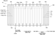
- first sealing members 82 are provided between (i) the end portions of the plate members 71, 72, 73, and 74 and (ii) the side walls 61c of the main body portion 61 of the box 60.
- the first sealing members 82 seal the four between-plate spaces 75 at both their end portions in the extending direction.
- both end portions of each between-plate space 75 in the extending direction are boundaries of the between-plate space 75 and do not overlap two plate members forming the between-plate space 75.
- the first sealing members 82 seal each between-plate space 75 at both its end portions in the extending direction. As a result, air is suppressed from going in and out of the between-plate space 75 through these end portions.
- Each first sealing member 82 is formed of a heat insulating material such as rock wool, etc.
- the material of the first sealing member 82 is not limited to the rock wool.
- the density of the first sealing member 82 is preferably 80 kg/m 3 or more.
- the density of the first sealing member 82 may be less than 80 kg/m 3 .
- the density of the heat insulating material forming the first sealing member 82 is preferably set in consideration of a ventilation capability of the first sealing member 82. The lower the ventilation capability of the first sealing member 82 is (the higher its density is), the smaller an amount of air leakage from each between-plate space 75 is. This improves the degree of sealing of the between-plate space 75.
- the lower end portions of the plate member 71 are provided with bent portions 71c.
- lower surfaces of the bent portions 71c are hatched in FIG. 7 .
- the bent portions 71c are provided at the respective lower end portions of the two side walls 71b of the plate member 71.
- a bent portion 71c of one of the two side walls 71b is provided on one side of the heat insulating block 92 in the base longitudinal direction (the left side in the sheet of FIG. 4 ), and formed by bending the lower end portion of this side wall 71b by substantially 90° toward one side of this side wall 71b in the base longitudinal direction.
- a bent portion 71c of the other of the two side walls 71b is provided on the other side of the heat insulating block 92 in the base longitudinal direction (the right side in the sheet of FIG. 4 ), and formed by bending the lower end portion of this side wall 71b by substantially 90° toward the other side of this side wall 71b in the base longitudinal direction.
- the bent portions 71c extend over the entire length of the plate member 71 in the extending direction.
- the bent portion 71c of each side wall 71b is provided with three protruding portions 71d.
- the three protruding portions 71d are provided at both end portions and center of each bent portion 71c in the extending direction.
- the length of each bent portion 71c is, except parts provided with the protruding portions 71d, substantially the same as that of the gap between the plate members 71 and 72 in the base longitudinal direction.
- the length of each bent portion 71c is, at parts provided with the protruding portions 71d, substantially the same as that of a gap between the plate members 71 and 73 in the base longitudinal direction.
- the lower end portions of the plate member 72 are provided with bent portions 72c.
- the bent portions 72c are provided at the respective lower end portions of the two side walls 72b of the plate member 72.
- a bent portion 72c of one of the two side walls 72b is provided on one side of the heat insulating block 92 in the base longitudinal direction (the left side in the sheet of FIG. 4 ), and formed by bending the lower end portion of this side wall 72b by substantially 90° toward the other side of this side wall 72b in the base longitudinal direction.
- a bent portion 72c of the other of the two side walls 72b is provided on the other side of the heat insulating block 92 in the base longitudinal direction (the right side in the sheet of FIG. 4 ), and formed by bending the lower end portion of this side wall 72b by substantially 90° toward one side of this side wall 72b in the base longitudinal direction.
- the bent portions 72c extend over the entire length of the plate member 72 in the extending direction.
- the length of each bent portion 72c is substantially the same as that of the gap between the plate members 71 and 72 in the base longitudinal direction.
- the bent portions 72c are provided above the bent portions 71c of the plate member 71.
- the bent portions 71c of the plate member 71 are fixed to the bent portions 72c of the plate member 72 by bolts (not illustrated), etc. That is, the plate members 71 and 72 are fixed to each other by the bent portions 71c and 72c.
- the bent portions 71c and 72c of the two plate members 71 and 72 forming the between-plate space 75a seal the between-plate space 75a at its lower end portions, i.e., end portions on the lower side in the up-down direction (equivalent to "one side in an orthogonal direction" of the present invention).
- the bent portions 71c and 72c function also as spacers that maintain the gap between the two plate members 71 and 72.
- the protruding portions 71d of the bent portions 71c of the plate member 71 function as spacers that maintain the gap between the plate members 72 and 73.
- the lower end portions of the plate member 73 are provided with bent portions 73c.
- lower surfaces of the bent portions 73c are hatched in FIG. 7 .
- the bent portions 73c are provided at the respective lower end portions of the two side walls 73b of the plate member 73.
- a bent portion 73c of one of the two side walls 73b is provided on one side of the heat insulating block 92 in the base longitudinal direction (the left side in the sheet of FIG. 4 ), and formed by bending the lower end portion of this side wall 73b by substantially 90° toward one side of this side wall 73b in the base longitudinal direction.
- a bent portion 73c of the other of the two side walls 73b is provided on the other side of the heat insulating block 92 in the base longitudinal direction (the right side in the sheet of FIG. 4 ), and formed by bending the lower end portion of this side wall 73b by substantially 90° toward the other side of this side wall 73b in the base longitudinal direction.
- each bent portion 73c extend over the entire length of the plate member 73 in the extending direction.
- the length of each bent portion 73c is substantially the same as that of the gap between the plate members 73 and 74 in the base longitudinal direction.
- attached boards 78 are attached to lower surfaces of the bent portions 73c which are respectively provided at the two side walls 73b of the plate member 73.
- the bent portion 73c of one of the two side walls 73b of the plate member 73 is provided on one side of the heat insulating block 92 in the base longitudinal direction (the upper side in the sheet of FIG. 7 ) as described above, and the attached boards 78 are attached to this bent portion 73c so as to reach one of the side walls 61b of the main body portion 61 on one side of this bent portion 73c in the base longitudinal direction.
- the bent portion 73c of the other of the two side walls 73b of the plate member 73 is provided on the other side of the heat insulating block 92 in the base longitudinal direction (the lower side in the sheet of FIG. 7 ) as described above, and the attached boards 78 are attached to this bent portion 73c so as to reach the other of the side walls 61b of the main body portion 61 on the other side of this bent portion 73c in the base longitudinal direction.
- the attached boards 78 function also as spacers that maintain the gap between the plate member 74 and the main body portion 61.
- three attached boards 78 are attached to each of the bent portions 73c provided at the two side walls 73b of the plate member 73.
- the three attached boards 78 attached to each bent portion 73c are provided at different positions in the extending direction.
- an attached board 78 provided on one side in the extending direction (the left side in the sheet of FIG. 7 ) is provided between (i) a protruding portion 71d provided on one side in the extending direction and (ii) a protruding portion 71d provided at the center in the extending direction among the three protruding portions 71d provided at each bent portion 71c.
- an attached board 78 provided on the other side in the extending direction (the right side in the sheet of FIG. 7 ) is provided between (i) a protruding portion 71d provided on the other side in the extending direction and (ii) the protruding portion 71d provided at the center in the extending direction among the three protruding portions 71d provided at each bent portion 71c.
- an attached board 78 provided at the center in the extending direction is provided at the same position as the protruding portion 71d provided at the center in the extending direction among the three protruding portions 71d of each bent portion 71c.
- the lower end portions of the plate member 74 are provided with bent portions 74c.
- the bent portions 74c are provided at the respective lower end portions of the two side walls 74b of the plate member 74.
- a bent portion 74c of one of the two side walls 74b is provided on one side of the heat insulating block 92 in the base longitudinal direction (the left side in the sheet of FIG. 4 ), and formed by bending the lower end portion of this side wall 74b by substantially 90° toward the other side of this side wall 74b in the base longitudinal direction.
- a bent portion 74c of the other of the two side walls 74b is provided on the other side of the heat insulating block 92 in the base longitudinal direction (the right side in the sheet of FIG. 4 ), and formed by bending the lower end portion of this side wall 74b by substantially 90° toward one side of this side wall 74b in the base longitudinal direction.
- the bent portions 74c extend over the entire length of the plate member 74 in the extending direction.
- the length of each bent portion 74c is substantially the same as that of the gap between the plate members 73 and 74 in the base longitudinal direction.
- the bent portions 74c are provided above the bent portions 73c of the plate member 73.
- the bent portions 73c of the plate member 73 are fixed to the bent portions 74c of the plate member 74 by bolts (not illustrated), etc. That is, the plate members 73 and 74 are fixed to each other by the bent portions 73c and 74c.
- the bent portions 73c and 74c of the two plate members 73 and 74 forming the between-plate space 75c seal the between-plate space 75c at its lower end portions, i.e., end portions on the lower side in the up-down direction (equivalent to the "one side in the orthogonal direction" of the present invention).
- the bent portions 73c and 74c function also as spacers that maintain the gap between the two plate members 73 and 74.
- the between-plate space 75a is closest to the heating unit 50 among the four between-plate spaces 75 as described above, and sealed by the bent portions 71c and 72c (equivalent to a "first bent portion” of the present invention).
- the between-plate space 75c is sealed by the bent portions 73c and 74c (equivalent to a "second bent portion" of the present invention).
- the bent portions 71c and 72c sealing the between-plate space 75a and the bent portions 73c and 74c sealing the between-plate space 75c are provided below the heating unit 50.
- the bent portions 71c and 72c and (ii) the bent portions 73c and 74c are provided at different positions in the up-down direction.
- the bent portions 71c and 72c are provided above the bent portions 73c and 74c.
- the bent portions 71c and 72c are closer to the heating unit 50 in the up-down direction than the bent portions 73c and 74c.
- second sealing members 83 are provided between (i) the lower end portions of the plate members 71, 72, 73, and 74 and (ii) the lower wall 61d of the main body portion 61 of the box 60.
- the second sealing members 83 are respectively provided on the both sides of the opening 68 provided at the main body portion 61 of the box 60 in the base longitudinal direction.
- the second sealing members 83 seal the between-plate spaces 75b and 75d at their lower end portions. That is, the between-plate spaces 75b and 75d are sealed at their lower end portions not by the bent portions but by the second sealing members 83.
- each two adjacent between-plate spaces are formed by adjacent three (equivalent to "a first plate member, second plate member, and third plate member” of the present invention) of the plate member 71, the plate member 72, the plate member 73, the plate member 74, and the main body portion 61 (the upper wall 61a and the two side walls 61b), and one of these two adjacent between-plate spaces is sealed by the bent portions 71c and 72c or the bent portions 73c and 74c while the other of these two adjacent between-plate spaces is sealed by a second sealing member 83.
- the between-plate space 75a provided between the plate members 71 and 72 is sealed by the bent portions 71c and 72c, and the between-plate space 75b provided between the plate members 72 and 73 is sealed by a second sealing member 83.
- lower end portions of the between-plate space 75b are boundaries of the between-plate space 75b and do not overlap the plate members 72 and 73 forming the between-plate space 75b.
- lower end portions of the between-plate space 75d are boundaries of the between-plate space 75d and do not overlap the plate member 74 and the main body portion 61 forming the between-plate space 75d.
- the second sealing members 83 seal the between-plate spaces 75b and 75d at their lower end portions. As a result, air is suppressed from going in and out of the between-plate spaces 75b and 75d through these lower end portions.
- the second sealing members 83 cover the lower surfaces (the surfaces provided on the side opposite to the between-plate space 75a in the up-down direction) of the bent portions 71c sealing the between-plate space 75a.
- the second sealing members 83 also cover the lower surfaces (the surfaces provided on the side opposite to the between-plate space 75c in the up-down direction) of the bent portions 73c sealing the between-plate space 75c. That is, each second sealing member 83 is equivalent to a "covering member" of the present invention. That is, the second sealing members 83 cover the lower surfaces of the bent portions 71c and 73c regarding the between-plate spaces 75a and 75c. Among all of the between-plate spaces 75, only the between-plate spaces 75a and 75c are sealed by the bent portions.
- one of the second sealing members 83 is provided on one side of the opening 68 in the base longitudinal direction (the left side in the sheet of FIG. 8 ) and, in this second sealing member 83, the thickness of the part covering one of the bent portions 71c sealing the between-plate space 75a is defined as the thickness Ta1 in the up-down direction.
- the thickness of the part covering one of the bent portions 73c sealing the between-plate space 75c is defined as the thickness Tb1 in the up-down direction.
- the thickness Ta1 is larger than the thickness Tb1.
- the other of the second sealing members 83 is provided on the other side of the opening 68 in the base longitudinal direction (the right side in the sheet of FIG. 8 ) and, in this second sealing member 83, the thickness of the part covering the other of the bent portions 71c sealing the between-plate space 75a is defined as the thickness Ta2 in the up-down direction.
- the thickness of the part covering the other of the bent portions 73c sealing the between-plate space 75c is defined as the thickness Tb2 in the up-down direction.
- the thickness Ta2 is larger than the thickness Tb2.
- Each second sealing member 83 is formed of a heat insulating material such as rock wool, etc.
- the material of the second sealing member 83 is not limited to the rock wool.
- the density of the second sealing member 83 is preferably 80 kg/m 3 or more.
- the density of the second sealing member 83 may be less than 80 kg/m 3 .
- the density of the heat insulating material forming the second sealing member 83 is preferably set in consideration of a ventilation capability of the second sealing member 83. The lower the ventilation capability of the second sealing member 83 is (the higher its density is), the smaller an amount of air leakage from each of the between-plate spaces 75a and 75c is. This improves the degree of sealing of each of the between-plate spaces 75a and 75c.
- each between-plate space 75 is provided with plural spacer members 81.
- the spacer members 81 are provided at corners of each between-plate space 75 which is a groove which is open downward.
- the spacer members 81 are provided at both end portions of an upper part of each between-plate space 75 in the base longitudinal direction.
- the bent portions 71c and 72c sealing the between-plate space 75a and (ii) spacer members 81 provided at the between-plate space 75b adjacent to the between-plate space 75a are provided at different positions in the up-down direction.
- the adjacent plate members 71 and 72 are fixed to each other by the bent portions 71c and 72c.
- the adjacent plate members 73 and 74 are fixed to each other by the bent portions 73c and 74c.
- the adjacent plate members 72 and 73 are fixed to each other by connecting members 84.
- the plate member 74 and the main body portion 61 of the box 60 are fixed to each other by connecting members 85.
- the connecting members 84 are provided in the between-plate space 75b.
- the connecting members 84 are provided at the center of an upper part of the between-plate space 75b which is a groove which is open downward, in the base longitudinal direction.
- the connecting members 84 are provided at both end portions of the between-plate space 75b in the extending direction.
- the plate members 72 and 73 are fixed to each other by the connecting members 84.
- the connecting members 85 are provided in the between-plate space 75d.
- the connecting members 85 are provided at the center of an upper part of the between-plate space 75d which is a groove which is open downward, in the base longitudinal direction.
- the connecting members 85 are provided at both end portions of the between-plate space 75d in the extending direction.
- the plate member 74 and the main body portion 61 of the box 60 are fixed to each other by the connecting members 85.
- the first heater 13 of the present embodiment is provided with the yarn running grooves 56 extending along the extending direction and includes the heating unit 50 configured to heat the yarns Y running in the yarn running grooves 56, the box 60 housing the heating unit 50, the plural plate members 71, 72, 73, and 74, the first sealing members 82, and the second sealing members 83.
- the plate members 71, 72, 73, and 74 and the upper wall 61a and two side walls 61b of the main body portion 61 of the box 60 oppose each other at intervals and are aligned in the direction away from the heating unit 50 on the virtual plane which intersects with the heating unit 50 and which is orthogonal to the extending direction.
- each between-plate space 75 is provided between two opposing plate members or between the plate member 74 and the main body portion 61.
- the plural air layers provided at the respective between-plate spaces 75 are aligned in the direction away from the heating unit 50 on the virtual plane which intersects with the heating unit 50 and which is orthogonal to the extending direction.
- each air layer has a relatively-low heat conductivity, adequate performance of heat insulation is achieved even when the thickness of the air layer is small. Because each between-plate space 75 is sealed at at least parts of its end portions by the first sealing members 82 and the second sealing members 83, air is suppressed from going inside and outside of the between-plate space 75. This suppresses the occurrence of convection in the air layer.
- each between-plate space 75 is sealed. With this arrangement, because the between-plate space 75 is sealed, air is reliably suppressed from going inside and outside of the between-plate space 75. It is therefore possible to further improve the performance of heat insulation by each air layer.
- the plate members 71, 72, 73, and 74 and the upper wall 61a and two side walls 61b of the main body portion 61 extend along the extending direction.
- the first sealing members 82 are formed of heat insulating materials, and seal each between-plate space 75 at both its end portions in the extending direction. With this arrangement, the first sealing members 82 seal the between-plate space 75 at both its end portions in a predetermined direction. As a result, air is suppressed from going in and out of the between-plate space 75 through these end portions.
- first sealing members 82 sealing the between-plate space 75 at both its end portions in the extending direction are formed of heat insulating materials, heat transfer via the first sealing members 82 is suppressed between each adjacent plate members and between the plate member 74 and the main body portion 61 of the box 60. It is therefore possible to further improve the performance of heat insulation by each air layer.
- the density of each first sealing member 82 is 80 kg/m 3 or more.
- the first heater 13 of the present embodiment further includes the spacer members 81 provided at each between-plate space 75.
- the spacer members 81 are provided in the between-plate spaces 75 so that the thickness of each between-plate space 75 is even. It is therefore possible to suppress the occurrence of convection in the air layers, and to further improve the performance of heat insulation by the air layers.
- spacer members 81 provided at one of each two adjacent between-plate spaces 75 and (ii) spacer members 81 provided at the other of each two adjacent between-plate spaces 75 are provided at different positions in the extending direction.
- spacer members 81 provided at one of each two adjacent between-plate spaces 75 are provided at the same positions in the extending direction as the spacer members 81 provided at the other of each two adjacent between-plate spaces 75, heat transfer via the spacer members 81 tends to occur between each adjacent plate members and between a plate member and the main body portion 61 of the box 60.
- the heat transfer via the spacer members 81 is suppressed between each adjacent plate members and between a plate member and the main body portion 61 and the box 60. It is therefore possible to further improve the performance of heat insulation by the air layers.
- the bent portions 71c and 72c formed by bending the lower end portions of the plate members 71 and 72 forming the between-plate space 75a seal the between-plate space 75a at its lower end portions. Furthermore, the bent portions 73c and 74c formed by bending the lower end portions of the plate members 73 and 74 forming the between-plate space 75c seal the between-plate space 75c at its lower end portions. In each two adjacent between-plate spaces 75, the bent portions 71c and 72c or the bent portions 73c and 74c seal one between-plate space 75 (75a, 75c) and are provided at different positions in the up-down direction from the spacer members 81 provided at the other between-plate space 75 (75b, 75d).
- the between-plate space 75a is sealed by the bent portions 71c and 72c
- the between-plate space 75c is sealed by the bent portions 73c and 74c.
- Each of the bent portions 71c, 72c, 73c, and 74c is a part of one of the plate members 71, 72, 73, and 74. Furthermore, the occurrence of heat transfer via the bent portions 71c, 72c, 73c, and 74c and the spacer members 81 is suppressed between each adjacent plate members and a plate member and the main body portion 61 of the box 60. It is therefore possible to further improve the performance of heat insulation by the air layers.
- the bent portions 71c and 72c function as spacers that maintain the gap between the plate members 71 and 72.
- the bent portions 73c and 74c function as spacers that maintain the gap between the plate members 73 and 74.
- the bent portions 71c and 72c and the bent portions 73c and 74c cause the thicknesses of the between-plate spaces 75a and 75c to be even.
- the bent portions 71c and 72c seal the between-plate space 75a at its lower end portions, and the bent portions 73c and 74c seal the between-plate space 75c at its lower end portions.
- the second sealing members 83 formed of heat insulating materials seal the between-plate spaces 75b and 75d at their lower end portions. When all the adjacent between-plate spaces 75 are sealed by bent portions, the bent portions sealing the between-plate spaces 75 continuously transfer heat between the plate members.
- the second sealing members 83 formed of heat insulating materials seal the between-plate spaces 75b and 75d. This suppresses heat transferred between the plate members 71 and 72 via the bent portions 71c and 72c from being transferred to the plate member 73.
- the bent portions 71c and 72c sealing the between-plate space 75a and (ii) the bent portions 73c and 74c sealing the between-plate space 75c are provided at different positions in the up-down direction.
- the bent portions 71c and 72c sealing the between-plate space 75a are provided at the same position in the up-down direction as the bent portions 73c and 74c sealing the between-plate space 75c, heat transfer via the bent portions 71c, 72c, 73c, and 74c may occur between the separated plate members.
- the occurrence of heat transfer via the bent portions 71c, 72c, 73c, and 74c is suppressed between the separated plate members. It is therefore possible to further improve the performance of heat insulation by the air layers.
- the second sealing members 83 cover (i) the surfaces of the bent portions 71c sealing the between-plate space 75a and (ii) the surfaces of the bent portions 73c sealing the between-plate space 75c.
- these surfaces of the bent portions 71c are provided on the side opposite to the between-plate space 75a in the up-down direction
- these surfaces of the bent portions 73c are provided on the side opposite to the between-plate space 75c in the up-down direction.
- the second sealing members 83 suppress heat radiation from the bent portions 71c and 73c. Especially, it is possible to reliably suppress heat radiation from the bent portions 71c of the plate member 71 which is provided in the vicinity of the heating unit 50 and whose temperature is high.
- the second sealing members 83 additionally function as the covering members covering (i) the surfaces of the bent portions 71c sealing the between-plate spaces 75a and (ii) the surfaces of the bent portions 73c sealing the between-plate space 75c. This simplifies the structure of the first heater 13 as compared to the case where the covering members are different members from the second sealing members 83.
- the second sealing members 83 seal the between-plate spaces 75b and 75d at their lower end portions and cover the lower surfaces of the bent portions 71c and 73c regarding the between-plate spaces 75a and 75c.
- the between-plate spaces 75b and 75d are not sealed by bent portions, and the between-plate spaces 75a and 75c are sealed by bent portions. This further improves the performance of heat insulation by the air layers while maintaining the airtightness of all of the between-plate spaces 75 only by the second sealing members 83.
- the bent portions 71c and 72c sealing the between-plate space 75a are closer to the heating unit 50 in the up-down direction than the bent portions 73c and 74c sealing the between-plate space 75c.
- the thicknesses Ta1 and Ta2 of the parts covering the bent portions 71c are respectively larger than the thicknesses Tb1 and Tb2 of the parts covering the bent portions 73c in the up-down direction. This reliably suppresses heat radiation from the bent portions 71c which are provided in the vicinity of the heating unit 50 in the up-down direction and whose temperature is high.
- the plate members 71 and 72 are fixed to each other by the bent portions 71c and 72c formed at their lower end portions. Furthermore, the plate members 73 and 74 are fixed to each other by the bent portions 73c and 74c formed at their lower end portions. At the upper walls 72a and 73a, the plate members 72 and 73 are fixed to each other by the connecting members 84. At the upper walls 74a and 61a, the plate member 74 and the main body portion 61 of the box 60 are fixed to each other by the connecting members 85. With this arrangement, the bent portions 71c and 72c by which the plate members 71 and 72 are fixed maintain the layer thickness of the air layer between the plate members 71 and 72.
- the bent portions 73c and 74c by which the plate members 73 and 74 are fixed maintain the layer thickness of the air layer between the plate members 73 and 74.
- the connecting members 84 by which the plate members 72 and 73 are fixed maintain the layer thickness of the air layer between the plate members 72 and 73.
- the connecting members 85 by which the plate member 74 and the main body portion 61 of the box 60 are fixed maintain the layer thickness of the air layer between the plate member 74 and the main body portion 61 of the box 60.
- the following junctions are separated from each other in the up-down direction: the junction (where the bent portions 71c and 72c are formed) between the plate members 71 and 72; the junction (where the bent portions 73c and 74c are formed) between the plate members 73 and 74; the junction (where the plate members 72 and 73 are connected by the connecting members 84) between the plate members 72 and 73; and the junction (where the plate member 74 and the main body portion 61 are connected by the connecting members 85) between the plate member 74 and the main body portion 61 of the box 60. It is therefore possible to suppress heat transfer between each adjacent plate members and between a plate member and the main body portion 61 and the box 60 via the junctions, and to further improve the performance of heat insulation by the air layers.
- the second sealing members 83 are formed of heat insulating materials and seal the between-plate spaces 75b and 75d at their lower end portions. With this arrangement, the second sealing members 83 seal the between-plate spaces 75b and 75d at their lower end portions. As a result, air is suppressed from going in and out of the between-plate spaces 75b and 75d through these end portions. Because the second sealing members 83 are formed of heat insulating materials, heat transfer via the second sealing members 83 is suppressed between the adjacent plate members 72 and 73 and between the plate member 74 and the main body portion 61 of the box 60. It is therefore possible to further improve the performance of heat insulation by the air layers.
- the density of each second sealing member 83 is 80 kg/m 3 or more.
- the layer thickness of each air layer is 5 mm or more and less than 15 mm.
- the thickness of the air layer is large, convection tends to occur.
- heat transfer tends to occur between each two adjacent plate members forming a between-plate space 75 and between the plate member 74 and the main body portion 61 of the box 60 forming a between-plate space 75.
- the between-plate space 75 is provided with the air layer.
- each adjacent plate members may make contact with each other and the plate member 74 and the main body portion 61 of the box 60 may make contact with each other.
- the thickness of the air layer is arranged to be able to suppress (i) the occurrence of convection in the air layer and (ii) the contact between each adjacent plate members and between the plate member 74 and the main body portion 61 of the box 60. It is therefore possible to further improve the performance of heat insulation by the air layer.
- the first heater 13 of the present embodiment further includes the heat insulation member 80 provided between the plate member 71 and the heating unit 50.
- the plate member 71 is closest to the heating unit 50 among the plural plate members 71, 72, 73, and 74.
- the bolt 59, etc. for fixation of each member forming the heating unit 50 is exposed to the surface of the heating unit 50 so that the surface of the heating unit 50 is not even. It is therefore difficult to provide, between the surface of the heating unit 50 and the plate member 71, an air layer whose thickness is even and whose performance of heat insulation is high.
- the heat insulation member 80 is provided between the heating unit 50 and the plate member 71. It is therefore possible to further suppress heat radiation from the heating unit 50 to the outside.
- the yarn running grooves 56 are defined in the heating unit 50. With this arrangement, the yarns Y are efficiently heated.
- the yarn running grooves 56 are open downward, and the four plate members 71, 72, 73, and 74 and the upper wall 61a and two side walls 61b of the main body portion 61 are provided not to oppose the lower ends of the yarn running grooves 56 in the up-down direction.
- a space for allowing the yarns Y to pass therethrough at the time of insertion of the yarns Y into the yarn running grooves 56 is provided below the lower ends of the yarn running grooves 56.
- the plate members 71, 72, 73, and 74 extend along the extending direction and form grooves which are open downward.
- the four plate members 71, 72, 73, and 74 and the upper wall 61a and two side walls 61b of the main body portion 61 are nested so that the innermost plate member 71 surrounds the heating unit 50.
- the between-plate space 75a is closest to the heating unit 50 among the four between-plate spaces 75, and the opposing surfaces of the two plate members 71 and 72 forming the between-plate space 75a are surfaces with a mirror finish.
- the mirror-finished surfaces of the plate members 71 and 72 suppress radiant heat from the heating unit 50. It is therefore possible to suppress heat transfer due to radiation, and to further reduce power consumption.
- cost increase occurs.
- only the surfaces of the plate members 71 and 72 forming the between-plate space 75a closest to the heating unit 50 among the between-plate spaces 75 are mirror-finished surfaces. It is therefore possible to suppress cost increase while suppressing radiant heat from the heating unit 50 most effectively.
- the present invention is applied to the first heater 13 of the false-twist texturing machine 1.
- the present invention is applicable to the second heater 19.
- the following will describe the case where the present invention is applied to the second heater 19.
- the second heater 19 is provided for one span. As shown in FIG. 9 and FIG. 10 , the second heater 19 includes plural heating units 150. As shown in FIG. 10 FIG. 11(b) , the heating units 150 extend along the up-down direction. In the present modification, the up-down direction is a "predetermined direction" of the present invention.
- each heating unit 150 includes a pipe 151 extending along the up-down direction and two pipes 152a and 152b inserted into the pipe 151.
- the pipe 151 is filled with a heating medium 154.
- upper end portions of pipes 151 of the heating units 150 are connected to each other by a pipe 153.
- the pipe 153 allows the heating medium 154 to circulate among the pipes 151 of the heating units 150.
- Each pipe 152a and each pipe 152b are yarn running paths of yarns Ya and Yb.
- the heating medium 154 is heated, air in the pipes 152a and 152b is heated, and the yarns Ya and Yb running in the pipes 152a and 152b are heated.
- the heating units 150 are housed in a box 160. Between the heating units 150 and an inner wall surface of the box 160, plate members 171, 172, 173, and 174 are provided.
- a main body portion 161 of the box 160 and the plate members 171, 172, 173, and 174 are long in the base longitudinal direction and rectangular in shape in a cross section orthogonal to the up-down direction.
- the main body portion 161 of the box 160 is equivalent to a "plate member" of the present invention.
- the plate members 171, 172, 173, and 174 oppose each other at intervals and are aligned.
- the plate members 171, 172, 173, and 174 are aligned in a direction away from the heating units 150 on a virtual plane (e.g., the sheet of FIG. 9 ) which intersects with the heating units 150 and which is orthogonal to the up-down direction.
- the innermost plate member 171 surrounds the heating units 150.
- Between-plate spaces 175a, 175b, and 175c is formed between two opposing plate members. Furthermore, a between-plate space 175d is formed between the plate member 174 and the main body portion 161. These four between-plate spaces 175a, 175b, 175c, and 175d (175) are respectively provided with air layers. That is, four air layers provided at the respective between-plate spaces 175 are aligned in the direction away from the heating units 150 on the virtual plane (e.g., the sheet of FIG. 9 ) which intersects with the heating units 150 and which is orthogonal to the up-down direction.
- the virtual plane e.g., the sheet of FIG. 9
- a sealing member 182 seals the between-plate spaces 175 at their upper end portions. Furthermore, a sealing member 183 seals the between-plate spaces 175 at their lower end portions.
- Each of the sealing members 182 and 183 is equivalent to a "first sealing member" of the present invention. Only one of the sealing members 182 and 183 is minimally required.
- the sealing member 182 may seal at least one of the between-plate spaces 175a, 175b, 175c, and 175d.
- the sealing member 183 may seal at least one of the between-plate spaces 175a, 175b, 175c, and 175d.
- This second heater 19 is able to reduce power consumption without increasing the size of the heater, in the same manner as the first heater 13 of the embodiment above.
- the first sealing members 82 seal each between-plate space 75 at both its end portions in the extending direction
- the second sealing members 83 seal the between-plate space 75 at its lower end portions.
- the disclosure is not limited to this.
- the first heater 13 may include only the first sealing members 82 or the second sealing members 83.
- the first heater 13 may be suitably arranged as long as it includes a sealing member sealing the between-plate space 75 at least at its partial end portions.
- the between-plate spaces 75 are sealed. However, the between-plate spaces 75 may not be sealed. Alternatively, only one or some of the between-plate spaces 75 may be sealed.
- the first sealing members 82 formed of heat insulating materials seal each between-plate space 75 at both its end portions in the extending direction.
- the first sealing members 82 may seal each between-plate space 75 at only one of both end portions of the between-plate space 75 in the extending direction.
- the first sealing members 82 may seal at least one of the plural between-plate spaces 75a, 75b, 75c, and 75d.
- the first sealing members 82 may not be formed of heat insulating materials.
- the plural spacer members 81 are provided in each between-plate space 75.
- One spacer member 81 may be provided for each between-plate space 75.
- the spacer members 81 may be provided for only one or some of the plural between-plate spaces 75.
- the spacer members 81 may not be provided for the between-plate spaces 75.
- spacer members 81 provided at one of each two adjacent between-plate spaces 75 and (ii) spacer members 81 provided at the other of each two adjacent between-plate spaces 75 are provided at different positions in the extending direction.
- the spacer members 81 provided at one of each two adjacent between-plate spaces 75 and (ii) the spacer members 81 provided at the other of each two adjacent between-plate spaces 75 may be provided at the same positions in the extending direction.
- the bent portions 71c and 72c or the bent portions 73c and 74c seal one between-plate space 75 (75a, 75c) and are provided at different positions in the up-down direction from spacer members 81 provided at the other between-plate space 75 (75b, 75d).
- the bent portions 71c and 72c and the spacer members 81 provided at the between-plate space 75b may be provided at the same position in the up-down direction and the bent portions 73c and 74c and the spacer members 81 provided at the between-plate space 75d may be provided at the same position in the up-down direction.
- the bent portions 71c and 72c seal the between-plate space 75a at its lower end portions
- the bent portions 73c and 74c seal the between-plate space 75c at its lower end portions
- the second sealing members 83 formed of heat insulating materials seal the between-plate spaces 75b and 75d at their lower end portions.
- the bent portions may not be formed and the second sealing members 83 may seal all of the between-plate spaces 75 at their lower end portions.
- the bent portions may not be formed and the second sealing members 83 may seal at least one of the between-plate spaces 75a, 75b, 75c, and 75d.
- the second sealing members 83 may not be formed of heat insulating materials.
- only the second sealing members 83 seal the between-plate spaces 75b and 75d at their lower end portions and cover (i) the surfaces of the bent portions 71c sealing the between-plate space 75a and (ii) the surfaces of the bent portions 73c sealing the between-plate space 75c.
- members sealing the between-plate spaces 75b and 75d at their lower end portions may be different from members covering (i) the surfaces of the bent portions 71c sealing the between-plate space 75a and (ii) the surfaces of the bent portions 73c sealing the between-plate space 75c.
- the second sealing members 83 formed of heat insulating materials may cover only the surfaces of the bent portions 71c sealing the between-plate space 75a closest to the heating unit 50 among the between-plate spaces sealed by the bent portions (i.e., the between-plate spaces 75a and 75c).
- the second sealing members 83 formed of heat insulating materials may not cover (i) the surfaces of the bent portions 71c sealing the between-plate space 75a and (ii) the surfaces of the bent portions 73c sealing the between-plate space 75c.
- the bent portions 71c and 72c sealing the between-plate space 75a and (ii) the bent portions 73c and 74c sealing the between-plate space 75c are provided at different positions in the up-down direction.
- the bent portions 71c and 72c and (ii) the bent portions 73c and 74c may be provided at the same position in the up-down direction.
- the thicknesses Ta1 and Ta2 of the parts covering the bent portions 71c are respectively larger than the thicknesses Tb1 and Tb2 of the parts covering the bent portions 73c in the up-down direction.
- the thickness Ta1 may be equal to or less than the thicknesses Tb1 and the thickness Ta2 may be equal to or less than the thickness Tb2.
- the plate members 72 and 73 are fixed to each other by the connecting members 84 at the upper walls 72a and 73a, and the plate member 74 and the main body portion 61 of the box 60 are fixed to each other by the connecting members 85 at the upper walls 74a and 61a.
- Each of the following junctions may be provided not at the upper walls of members corresponding to each junction but at, e.g., the lower end portions of the members: the junction (where the plate members 72 and 73 are connected by the connecting members 84) between the plate members 72 and 73; and the junction (where the plate member 74 and the main body portion 61 are connected by the connecting members 85) between the plate member 74 and the main body portion 61 of the box 60.
- the heat insulation member 80 is provided between the plate member 71 and the heating unit 50.
- the heat insulation member 80 may not be provided.
- the four plate members 71, 72, 73, and 74 are provided between the main body portion 61 of the box 60 and the heating unit 50, and the four between-plate spaces 75 are respectively provided between the plate members 71 and 72, the plate members 72 and 73, the plate members 73 and 74, and the plate member 74 and the main body portion 61.
- the minimum number of between-plate spaces 75 is two. That is, the minimum number of plate members of the present invention is three. The number of between-plate spaces 75 may be five or more.
- the four plate members 71, 72, 73, and 74 and the upper wall 61a and two side walls 61b of the main body portion 61 are provided not to oppose the lower ends of the yarn running grooves 56 in the up-down direction.
- the disclosure is not limited to this. That is, the plate members forming the between-plate spaces may be provided to oppose the lower ends of the yarn running grooves 56 in the up-down direction.
- the plate members provided to oppose the lower ends of the yarn running grooves 56 in the up-down direction are movable not to oppose these lower ends or detachably attached to the heater.
- the plate members 71, 72, 73, and 74 extend along the extending direction and form grooves which are open downward.
- the disclosure is not limited to this.
- the plate members may be flat plates which are not bent.
- the between-plate space 75a is closest to the heating unit 50 among the four between-plate spaces 75, and the opposing surfaces of the two plate members 71 and 72 forming the between-plate space 75a are surfaces with a mirror finish.
- the disclosure is not limited to this.
- at least a surface of the plate member 71 which is closer to the heating unit 50 defines the between-plate space 75a and is a surface with a mirror finish.
- All surfaces of the plate members 71 to 74 and the main body portion 61 may be surfaces with a mirror finish.
- the surfaces of the plate members 71 to 74 and the main body portion 61 may not be surfaces with a mirror finish.
- the heating unit 50 is provided with the entire yarn running grooves 56.
- the disclosure is not limited to this.
- the heating unit 50 may define a part of each yarn running groove 56. That is, the heating unit 50 may define only the bottom portion of the yarn running groove 56. Alternatively, the heating unit 50 may define only side portions of the yarn running groove 56.
- the yarns Y receive heat from the heating blocks 52 via the yarn contacted surfaces 55 by making contact with the yarn contacted surfaces 55 in the heating unit 50.
- the heating unit 50 may adopt a contactless manner of heating the yarns Y by means of heated air.
- the heating unit 50 includes the heat source 51 and the heating blocks 52 heated by the heat source 51.
- the disclosure is not limited to this.
- the heating unit may be structured so that a heating medium such as DOWTHERM circulates in a hollow member.
- the heater of the present invention is applied to the false-twist texturing machine 1 configured to false-twist the yarns Y.
- the disclosure is not limited to this.
- the heater of the present invention is applicable to a processor configured to perform, for yarns formed of synthetic fibers, various processes such as yarn combining in addition to false twisting.
Landscapes
- Engineering & Computer Science (AREA)
- Textile Engineering (AREA)
- Mechanical Engineering (AREA)
- Yarns And Mechanical Finishing Of Yarns Or Ropes (AREA)
Abstract
Description
- The present invention relates to a yarn heater configured to heat a yarn and a false-twist texturing machine including this yarn heater.
- A known yarn heater is configured to heat a running yarn formed of synthetic fibers in a processor configured to perform various processes such as yarn combining and false twisting. A false-twist texturing machine of Patent Literature 1 (
Japanese Unexamined Patent Publication No. 2016-056494 - It is desired to reduce power consumption in the above-described yarn heater. To reduce the power consumption, it is conceivable to increase the thickness of the heat insulating material to reduce an amount of heat radiation from the heating unit to the outside. However, the increase in thickness of the heat insulating material disadvantageously increases the size of the yarn heater.
- An object of the present invention is to provide a yarn heater that reduces power consumption and a false-twist texturing machine including this yarn heater, without increasing the size of the heater.
- According to a first aspect of the invention, a yarn heater is provided with a yarn running path in which a yarn runs. This yarn heater includes: a heating unit which extends along a predetermined direction and which is configured to heat the yarn running in the yarn running path extending in the predetermined direction; at least three plate members which oppose each other at intervals and are aligned in a direction away from the heating unit on a virtual plane which is orthogonal to the predetermined direction and which intersects with the heating unit; and a sealing member sealing at least one of at least two between-plate spaces at at least a part of an end portion of the at least one of the at least two between-plate spaces each of which is provided between opposing two of the at least three plate members, air layers provided at the at least two between-plate spaces being aligned in the direction away from the heating unit on the virtual plane.
- In this regard, "the end portion of the at least one of the at least two between-plate spaces each of which is provided between opposing two of the at least three plate members" is a boundary of a between-plate space and does not overlap the two opposing plate members forming the between-plate space.
- According to this aspect, heat radiation from the heating unit to the outside is suppressed by the air layers aligned in the direction away from the heating unit on the virtual plane. Because each air layer has a relatively-low heat conductivity, adequate performance of heat insulation is achieved even when the thickness of the air layer is small. Because the at least one between-plate space is sealed at at least a part of its end portion by the sealing member, air is suppressed from going inside and outside of the at least one between-plate space. This suppresses the occurrence of convection in the air layer. It is therefore possible to suppress the occurrence of heat transfer between two adjacent plate members forming a between-plate space, and to further improve the performance of heat insulation by an air layer. This reduces power consumption without increasing the size of the heater.
- According to a second aspect of the invention, the yarn heater of the first aspect is arranged such that the at least one of the at least two between-plate spaces is sealed.
- According to this aspect, because the at least one between-plate space is sealed, air is reliably suppressed from going inside and outside of the at least one between-plate space. It is therefore possible to further improve the performance of heat insulation by the air layer.
- According to a third aspect of the invention, the yarn heater of the first or second aspect is arranged such that the at least three plate members extend along the predetermined direction. Furthermore, the sealing member includes first sealing members which are formed of heat insulating materials and which seal the at least one of the at least two between-plate spaces at both end portions of the at least one of the at least two between-plate spaces in the predetermined direction.
- According to this aspect, the first sealing members seal the at least one between-plate space at both its end portions in the predetermined direction. As a result, air is suppressed from going in and out of the at least one between-plate space through these end portions. Because the first sealing members sealing the at least one between-plate space at both its end portions in the predetermined direction are formed of heat insulating materials, heat transfer via the first sealing members is suppressed between adjacent plate members. It is therefore possible to further improve the performance of heat insulation by the air layer.
- According to a fourth aspect of the invention, the yarn heater of the third aspect is arranged such that the density of each of the first sealing members is 80 kg/m3 or more.
- According to this aspect, because each first sealing member has a high density, air is further reliably suppressed from going inside and outside of each between-plate space through the first sealing member. It is therefore possible to further reliably seal the between-plate space.
- According to a fifth aspect of the invention, the yarn heater of any one of the first to fourth aspects includes a spacer member provided in each of the at least two between-plate spaces.
- When the thickness of each between-plate space is uneven, convection tends to occur in each air layer because of a temperature difference in the between-plate space. In this regard, the air layer is provided at the between-plate space. According to this aspect, the spacer member is provided in the between-plate space so that the thickness of the between-plate space is even. It is therefore possible to suppress the occurrence of convection in the air layer, and to further improve the performance of heat insulation by the air layer.
- According to a sixth aspect of the invention, the yarn heater of the fifth aspect is arranged such that spacer members which are respectively provided in two adjacent between-plate spaces are provided at different positions in the predetermined direction.
- When spacer members which are respectively provided at two adjacent between-plate spaces are provided at the same position in the predetermined direction, heat transfer via these two spacer members tends to occur between adjacent plate members. According to this aspect, the heat transfer via the two spacer members is suppressed between the adjacent plate members. It is therefore possible to further improve the performance of heat insulation by air layers.
- According to a seventh aspect of the invention, the yarn heater of the fifth or sixth aspect is arranged such that the two of the at least three plate members form the each of the at least two between-plate spaces, one end portions of the two of the at least three plate members are provided on one side in an orthogonal direction orthogonal to the predetermined direction and bent so as to form bent portions sealing the at least one of the at least two between-plate spaces at one end portion of the at least one of the at least two between-plate spaces on the one side in the orthogonal direction, and the bent portions seal one of the two adjacent between-plate spaces and are provided at different positions in the orthogonal direction from one of the spacer members which is provided at the other of the two adjacent between-plate spaces.
- According to this aspect, each between-plate space is sealed by the bent portions which are parts of two plate members. Furthermore, heat transfer via the bent portions and the spacer members is suppressed between adjacent plate members. It is therefore possible to further improve the performance of heat insulation by each air layer.
- According to an eighth aspect of the invention, the yarn heater of the seventh aspect is arranged such that the two of the at least three plate members form the each of the at least two between-plate members, and the bent portions function as spacers that maintain a gap between the two of the at least three plate members.
- According to this aspect, the bent portions cause the thickness of each between-plate space to be even.
- According to a ninth aspect of the invention, the yarn heater of the seventh or eighth aspect is arranged such that, when adjacent three of the at least three plate members are a first plate member, a second plate member, and a third plate member, one of the at least two between-plate spaces is provided between the first plate member and the second plate member and sealed at one end portion of the one of the at least two between-plate spaces on the one side in the orthogonal direction by the bent portions formed by bending one end portion of the first plate member and one end portion of the second plate member on the one side in the orthogonal direction. Furthermore, the sealing member includes a second sealing member formed of a heat insulating material, another of the at least two between-plate spaces is provided between the second plate member and the third plate member, and the second sealing member seals the another of the at least two between-plate spaces at one end portion of the another of the at least two between-plate spaces on the one side in the orthogonal direction.
- When all of adjacent between-plate spaces (i.e., a between-plate space provided between the first and second plate members and a between-plate space provided between the second and third plate members) are sealed by the bent portions, the bent portions sealing the between-plate spaces continuously transfer heat between plate members. According to this aspect, the second sealing member formed of the heat insulating material seals a between-plate space provided between the second and third plate members. It is therefore possible to suppress heat transferred between the first and second plate members via the bent portions of the plate members from being transferred to the third plate member. It is therefore possible to further improve the performance of heat insulation by each air layer while maintaining the airtightness of each between-plate space.
- According to a tenth aspect of the invention, the yarn heater of the ninth aspect is arranged such that, when one of three adjacent between-plate spaces is closest to the heating unit, another of the three adjacent between-plate spaces is farthest from the heating unit, and each of the one and the another of the three adjacent between-plate spaces is sealed by the bent portions, the bent portions sealing the each of the one and the another of the three adjacent between-plate spaces are provided at different positions in the orthogonal direction.
- When the bent portions which seal these two between-plate spaces are provided at the same position in the orthogonal direction, heat transfer via these two bent portions may occur between separated plate members. According to this aspect, the heat transfer via the two bent portions is suppressed between the separated plate members. It is therefore possible to further improve the performance of heat insulation by air layers.
- According to an eleventh aspect of the invention, the yarn heater of the ninth or tenth aspect includes a covering member which is formed of a heat insulating material and which covers surfaces of the bent portions on a side opposite to one of at least one first between-plate space which is included in the at least two between-plate spaces and which is sealed by the bent portions, the bent portions sealing the one of the at least one first between-plate space at least, and the one of the at least one first between-plate space being closest to the heating unit.
- According to this aspect, the covering member suppresses heat radiation from the bent portions. Especially, it is possible to reliably suppress heat radiation from a bent portion of a plate member provided in the vicinity of the heating unit and whose temperature is high.
- According to a twelfth aspect of the invention, the yarn heater of the eleventh aspect is arranged such that the second sealing member additionally functions as the covering member.
- According to this aspect, the structure of the yarn heater is simplified as compared to the case where the covering member is different from the second sealing member.
- According to a thirteenth aspect of the invention, the yarn heater of the twelfth aspect of the invention is arranged such that second between-plate spaces are included in the at least two between-plate spaces and not sealed by the bent portions, the bent portions regard all of first between-plate spaces, and the second sealing member seals all of the second between-plate spaces at one end portions of the second between-plate spaces on the one side in the orthogonal direction and covers the surfaces of the bent portions on a side opposite to the all of the first between-plate spaces.
- According to this aspect, the performance of heat insulation by air layers is further improved while maintaining the airtightness of all between-plate spaces only by the second sealing member.
- According to a fourteenth aspect of the invention, the yarn heater of the twelfth or thirteenth aspect is arranged such that the at least three plate members cover the entire heating unit in the orthogonal direction, the one of the first between-plate spaces is closest to the heating unit and sealed by a first bent portion which is included in the bent portions, the first bent portion is closer to the heating unit in the orthogonal direction than a second bent portion which is included in the bent portions and which seals another of the first between-plate spaces, and in the second sealing member, the thickness of a part covering the first bent portion is larger than the thickness of a part covering the second bent portion in the orthogonal direction.
- This reliably suppresses heat radiation from the first bent portion which is provided in the vicinity of the heating unit in the orthogonal direction and whose temperature is high.
- According to a fifteenth aspect of the invention, the yarn heater of any one of the ninth to fourteenth aspects includes a connecting member connecting adjacent two of the at least three plate members to each other. In this yarn heater, the first plate member and the second plate member are connected to each other by the bent portions, and the second plate member and the third plate member are connected to each other by the connecting member at an end portion of the second plate member and an end portion of the third plate member on the other side opposite to the one side in the orthogonal direction.
- According to this aspect, the bent portions fixing the first and second plate members to each other maintain the layer thickness of an air layer provided between the first and second plate members. Furthermore, the connecting member fixing the second and third plate members to each other maintain the layer thickness of an air layer provided between the second and third plate members. In this regard, when a junction between the first and second plate members and a junction between the second and third plate members are close to each other, heat transfer via these two junctions tends to occur between the first and third plate members. According to this aspect, the junction (where the bent portions are formed) between the first and second plate members is separated from the junction (where the second and third plate members are connected by the connecting member) between the second and third plate members in the orthogonal direction. It is therefore possible to suppress heat transfer between the first and third plate members via the two junctions, and to further improve the performance of heat insulation by air layers.
- According to a sixteenth aspect of the invention, the yarn heater of any one of the first to eighth aspects is arranged such that the sealing member includes a second sealing member which is formed of a heat insulating material and which seals the at least one of the at least two between-plate spaces at one end portion of the at least one of the at least two between-plate spaces on one side in an orthogonal direction orthogonal to the predetermined direction.
- According to this aspect, the second sealing member seals at least one between-plate space at its one end portion on the one side in the orthogonal direction. As a result, air is suppressed from going in and out of the between-plate space through this end portion. Because the second sealing member is formed of the heat insulating material, heat transfer via the second sealing member is suppressed between adjacent plate members. It is therefore possible to further improve the performance of heat insulation by each air layer.
- According to a seventeenth aspect of the invention, the yarn heater of any one of the ninth to sixteenth aspects is arranged such that the density of the second sealing member is 80 kg/m3 or more.
- According to this aspect, because the second sealing member has a high density, air is further reliably suppressed from going inside and outside of each between-plate space through the second sealing member. It is therefore possible to further reliably seal each between-plate space.
- According to an eighteenth aspect of the invention, the yarn heater of any one of the first to seventeenth aspects is arranged such that the layer thickness of each of the air layers is 5 mm or more and less than 15 mm.
- When the thickness of each air layer is large, convection tends to occur. When convection occurs in each air layer, heat transfer tends to occur between two adjacent plate members forming a between-plate space provided with the air layer. Meanwhile, when the thickness of the air layer is small, the adjacent plate members may make contact with each other. In this case, heat transfer occurs between the adjacent plate members making contact with each other at a junction. According to this aspect, the thickness of the air layer is arranged to be able to suppress (i) the occurrence of convection in the air layer and (ii) the contact between the adjacent plate members. It is therefore possible to further improve the performance of heat insulation by the air layer.
- According to a nineteenth aspect of the invention, the yarn heater of any one of the first to eighteenth aspects includes a heat insulation member provided between one of the at least three plate members and the heating unit, the one of the at least three plate members being closest to the heating unit.
- A bolt, etc. for fixation of each member forming the heating unit is exposed to a surface of the heating unit so that the surface of the heating unit is not even. It is therefore difficult to provide, between the surface of the heating unit and a plate member, an air layer whose thickness is even and whose performance of heat insulation is high. According to this aspect, the heat insulation member is provided between the heating unit and the plate member. It is therefore possible to further suppress heat radiation from the heating unit to the outside.
- According to a twentieth aspect of the invention, the yarn heater of any one of the first to nineteenth aspects is arranged such that the yarn running path is at least partially defined in the heating unit and is a yarn running groove which is open in an open direction orthogonal to the predetermined direction.
- According to this aspect, the yarn is efficiently heated.
- According to a 21st aspect of the invention, the yarn heater of the twentieth aspect is arranged such that the at least three plate members are provided not to oppose an open end of the yarn running groove in the open direction.
- According to this aspect, a space for allowing the yarn to pass therethrough at the time of insertion of the yarn into the yarn running groove is provided to oppose the open end of the yarn running groove.
- According to a 22nd aspect of the invention, the yarn heater of the 21st aspect is arranged such that each of the at least three plate members extends along the predetermined direction and forms a groove which is open in the open direction, and the at least three plate members are nested so that the innermost one of the at least three plate members surrounds the heating unit.
- This makes it possible to surround the heating unit with an air layer provided at a between-plate space between each two adjacent plate members, while providing a space for allowing the yarn to pass therethrough at the time of insertion of the yarn into the yarn running groove. It is therefore possible to effectively suppress heat radiation from the heating unit to the outside.
- According to a 23rd aspect of the invention, the yarn heater of any one of the first to 22nd aspects is arranged such that the one of the at least two between-plate spaces is closest to the heating unit, the two of the at least three plate members form the one of the between-plate spaces, one of opposing surfaces of the two of the at least three plate members is closer to the heating unit, and at least the one of the opposing surfaces of the two of the at least three plate members is a surface with a mirror finish.
- According to this aspect, at least one of the opposing surfaces of two plate members is a surface with a mirror finish and suppresses radiant heat from the heating unit. It is therefore possible to suppress heat transfer due to radiation, and to further reduce power consumption. When many plate members are provided with surfaces with a mirror finish, cost increase occurs. According to this aspect, a surface of a plate member defining a between-plate space closest to the heating unit is a surface with a mirror-finish. It is therefore possible to suppress cost increase while suppressing radiant heat from the heating unit most effectively. In this regard, dirt tends to be conspicuous on the mirror-finished surfaces. According to this aspect, because the surface of the plate member defining the above-described between-plate space cannot be seen from the outside and is the mirror-finished surface, the dirt on the mirror-finished surface is unlikely to be noticed.
- According to a 24th aspect of the invention, a false-twist texturing machine is configured to false-twist a yarn and includes the yarn heater according to any one of the first to 23rd aspects.
- According to this aspect, power consumption is reduced without increasing the size of the yarn heater.
-
- [
FIG. 1] FIG. 1 is a profile of a false-twist texturing machine of an embodiment of the present invention. - [
FIG. 2] FIG. 2 is a schematic diagram of the false-twist texturing machine, expanded along paths of yarns. - [
FIG. 3] FIG. 3 shows a first heater. - [
FIG. 4] FIG. 4 is a cross section taken along a line IV-IV in the first heater shown inFIG. 3 . - [
FIG. 5] FIG. 5(a) is an enlarged view of a heating unit shown inFIG. 4 , andFIG. 5(b) is a cross section taken along a line b-b in the heating unit shown inFIG. 5(a) . - [
FIG. 6] FIG. 6 is a cross section taken along a line VI-VI in the first heater shown inFIG. 4 . - [
FIG. 7] FIG. 7 is a cross section taken along a line VII-VII in the first heater shown inFIG. 4 . - [
FIG. 8] FIG. 8 is a cross section which is used for explanation of sizes and which is taken along a line IV-IV in the first heater shown inFIG. 3 . - [
FIG. 9] FIG. 9 is a cross section which is used for explanation of a modification of the present embodiment and which is taken along a line in a direction orthogonal to an up-down direction of a second heater. - [
FIG. 10] FIG. 10 is a cross section taken along a line X-X inFIG. 9 . - [
FIG. 11] FIG. 11(a) is an enlarged view of a heating unit shown inFIG. 9 , andFIG. 11(b) is a cross section taken along a line b-b inFIG. 11(a) . - The following will describe a false-
twist texturing machine 1 of a preferred embodiment of the present invention, with reference toFIG. 1 . A vertical direction to the sheet ofFIG. 1 is defined as a base longitudinal direction, and a left-right direction to the sheet is defined as a base width direction. A direction orthogonal to both the base longitudinal direction and the base width direction is defined as an up-down direction in which the gravity acts. In this regard, the base longitudinal direction and the base width direction are substantially in parallel to the horizontal direction. - The false-
twist texturing machine 1 is able to perform false twisting of yarns Y (i.e., to false-twist the yarns Y) made of synthetic fibers such as nylon (polyamide fibers) and polyester. The false-twist texturing machine 1 includes ayarn supplying part 2 for supplying the yarns Y, aprocessing part 3 configured to false-twist the yarns Y supplied from theyarn supplying part 2, and a windingpart 4 configured to wind the yarns Y processed by theprocessing part 3 onto winding bobbins Bw. Components of theyarn supplying part 2, theprocessing part 3, and the windingpart 4 are aligned to form plural lines in the base longitudinal direction (seeFIG. 2 ). The base longitudinal direction is a direction orthogonal to a running plane (the sheet ofFIG. 1 ) of the yarns Y, which is formed of the yarn paths extending from theyarn supplying part 2 to the windingpart 4 via theprocessing part 3. - The
yarn supplying part 2 includes acreel stand 5 retaining plural yarn supply packages Ps. Theyarn supplying part 2 is configured to supply the plural yarns Y to theprocessing part 3. Theprocessing part 3 is configured to false-twist the yarns Y supplied from the yarn supply packages Ps. In theprocessing part 3, the following members are placed in this order from the upstream side in a yarn running direction: eachfirst feed roller 11; each twist-stoppingguide 12; each first heater 13 (equivalent to a yarn heater of the present invention); each cooler 14; each false-twistingdevice 15; eachsecond feed roller 16; each interlacingdevice 17; eachthird feed roller 18; asecond heater 19; and eachfourth feed roller 20. The windingpart 4 includes plural windingdevices 21. Each windingdevice 21 is configured to wind a yarn Y false-twisted by theprocessing part 3 onto a winding bobbin Bw, so as to form a wound package Pw. - The false-
twist texturing machine 1 includes a main base 8 and a windingbase 9 that are spaced apart from each other in the base width direction. The main base 8 and the windingbase 9 extend to substantially the same length in the base longitudinal direction. The main base 8 and the windingbase 9 oppose each other in the base width direction. An upper part of the main base 8 is connected to an upper part of the windingbase 9 by a supportingframe 10. Each device forming theprocessing part 3 is mainly attached to the main base 8 or the supportingframe 10. Each device forming the windingpart 4 is attached to the windingbase 9. The main base 8, the windingbase 9, and the supportingframe 10 form a working space A where an operator performs an operation such as yarn threading to each device. The yarn paths are formed so that the yarns Y mainly run around the working space A. - The false-
twist texturing machine 1 includes units termed spans each of which includes a pair of the main base 8 and the windingbase 9 provided to oppose each other. In one span, processing units (which are also termed spindles) in which yarn paths are formed to pass the devices constituting theprocessing part 3 are aligned in the base longitudinal direction. With this arrangement, in one span, plural yarns Y running while being aligned in the base longitudinal direction can be simultaneously false-twisted. In the false-twist texturing machine 1, the spans are placed in a left-right symmetrical manner to the sheet, with a center line C in the base width direction of the main base 8 set as a symmetry axis. The main base 8 is shared between the left span and the right span. - The following will describe the structure of the
processing part 3 with reference toFIG. 1 andFIG. 2 . Eachfirst feed roller 11 is configured to unwind a yarn Y from a yarn supply package Ps attached to theyarn supplying part 2, and to feed the yarn Y to afirst heater 13. As shown inFIG. 2 , for example, thefirst feed roller 11 is configured to feed one yarn Y to thefirst heater 13. Thefirst feed roller 11 may be able to feed adjacent yarns Y to the downstream side in the yarn running direction. Each twist-stoppingguide 12 is provided to prevent the twist of a yarn Y formed by a false-twistingdevice 15 from being propagated to the upstream side of the twist-stoppingguide 12 in the yarn running direction. - Each
first heater 13 is configured to heat yarns Y supplied from somefirst feed rollers 11 to a predetermined processing temperature. As shown inFIG. 2 , for example, thefirst heater 13 is able to heat two yarns Y. Thefirst heater 13 will be detailed later. - Each cooler 14 is configured to cool a yarn Y heated by a
first heater 13. As shown inFIG. 2 , for example, the cooler 14 is configured to cool one yarn Y. The cooler 14 may be able to simultaneously cool plural yarns Y. - Each false-twisting
device 15 is provided downstream of a cooler 14 in the yarn running direction. The false-twistingdevice 15 is configured to twist a yarn Y. The false-twistingdevice 15 is, e.g., a so-called disc-friction-type false-twisting device. However, the disclosure is not limited to this. - Each
second feed roller 16 is configured to feed a yarn Y processed by a false-twistingdevice 15 to an interlacingdevice 17. The conveyance speed of conveying the yarn Y by thesecond feed roller 16 is higher than the conveyance speed of conveying the yarn Y by eachfirst feed roller 11. With this arrangement, the yarn Y is drawn and false-twisted between thefirst feed roller 11 and thesecond feed roller 16. - Each interlacing
device 17 is configured to interlace a yarn Y. The interlacingdevice 17 includes, e.g., a known interlace nozzle configured to interlace the yarn Y by means of an airflow. - Each
third feed roller 18 is configured to feed a yarn Y running on the downstream side of an interlacingdevice 17 in the yarn running direction, to thesecond heater 19. As shown inFIG. 2 , for example, thethird feed roller 18 is configured to feed one yarn Y to thesecond heater 19. Thethird feed roller 18 may be able to feed adjacent yarns Y to the downstream side in the yarn running direction. The conveyance speed of conveying the yarn Y by thethird feed roller 18 is lower than the conveyance speed of conveying the yarn Y by eachsecond feed roller 16. The yarn Y is therefore relaxed between thesecond feed roller 16 and thethird feed roller 18. - The
second heater 19 is configured to heat yarns Y fed from somethird feed rollers 18. Thesecond heater 19 extends along the vertical direction, and onesecond heater 19 is provided in one span. - Each
fourth feed roller 20 is configured to feed a yarn Y heated by thesecond heater 19 to a windingdevice 21. As shown inFIG. 2 , for example, thefourth feed roller 20 is able to feed one yarn Y to the windingdevice 21. Thefourth feed roller 20 may be able to feed adjacent yarns Y to the downstream side in the yarn running direction. The conveyance speed of conveying the yarn Y by thefourth feed roller 20 is lower than the conveyance speed of conveying the yarn Y by eachthird feed roller 18. The yarn Y is therefore relaxed between thethird feed roller 18 and thefourth feed roller 20. - In the
processing part 3 arranged as described above, the yarn Y drawn between thefirst feed roller 11 and thesecond feed roller 16 is twisted by the false-twistingdevice 15. The twist formed by the false-twistingdevice 15 propagates to the twist-stoppingguide 12, but does not propagate to the upstream side of the twist-stoppingguide 12 in the yarn running direction. The yarn Y which is twisted and drawn is heated by thefirst heater 13 and thermally set. After that, the yarn Y is cooled by the cooler 14. The yarn Y is untwisted on the downstream side of the false-twistingdevice 15 in the yarn running direction. However, the yarn Y is maintained to be wavy in shape on account of the thermal setting described above (i.e., the crimp contraction of the yarn Y is maintained). - The false-twisted yarn Y is interlaced by the interlacing
device 17 while being relaxed between thesecond feed roller 16 and thethird feed roller 18. After that, the yarn Y is guided toward the downstream side in the yarn running direction. Furthermore, the yarn Y is thermally processed by thesecond heater 19 while being relaxed between thethird feed roller 18 and thefourth feed roller 20. Finally, the yarn Y fed from thefourth feed roller 20 is wound by the windingdevice 21. - The following will describe the structure of the winding
part 4 with reference toFIG. 2 . The windingpart 4 includes plural windingdevices 21. Each windingdevice 21 is able to wind a yarn Y onto one winding bobbin Bw. The windingdevice 21 includes afulcrum guide 31, atraverse device 32, and acradle 33. Thefulcrum guide 31 is a guide functioning as a fulcrum when the yarn Y is traversed. Thetraverse device 32 is able to traverse the yarn Y by means of atraverse guide 34. Thecradle 33 is configured to rotatably support the winding bobbin Bw. Acontact roller 35 is provided in the vicinity of thecradle 33. Thecontact roller 35 is configured to make contact with a surface of a wound package Pw so as to apply a contact pressure to the surface of the wound package Pw. In the windingpart 4 arranged as described above, the yarn Y fed by thefourth feed roller 20 described above is wound onto the winding bobbin Bw by each windingdevice 21 so as to form the wound package Pw. - The following will detail the structure of the
first heater 13 with reference toFIG. 3 to FIG. 8 .FIG. 7 does not show asecond sealing member 83, for the sake of convenience.FIG. 8 is used for explaining the thicknesses Ta1, Tb1, Ta2, and Tb2 described later, and may not show unnecessary reference numerals, etc. - As shown in
FIG. 3 , thefirst heater 13 extends in a predetermined extending direction (equivalent to a "predetermined direction" of the present invention) orthogonal to the base longitudinal direction. In the present embodiment, the extending direction is in parallel to the base width direction. The extending direction may be tilted with respect to the base width direction. - As described later, the
first heater 13 is provided with yarn running grooves 56 (seeFIG. 5 ) extending along the extending direction. Eachyarn running groove 56 is equivalent to a "yarn running path" of the present invention. Thefirst heater 13 is configured to heat a yarn Y running from one side to the other side in the extending direction of eachyarn running groove 56. In the present embodiment, thefirst heater 13 is able to heat two yarns Y (yarns Ya and Yb: seeFIG. 5 ). - As shown in
FIG. 4 , thefirst heater 13 mainly includes aheating unit 50,heat insulating blocks box 60,plate members FIG. 5(b) , theheating unit 50 is provided with each yarn running groove 56 (56a, 56b) extending along the extending direction. Each yarn running groove 56 (56a, 56b) is open downward. Theheating unit 50 is configured to heat each yarn Y (yarn Ya, Yb) running in the yarn running groove 56 (56a, 56b). As shown inFIG. 4 , thebox 60 houses theheating unit 50 and theheat insulating blocks plate members heating unit 50 and an inner wall surface of thebox 60. - As shown in
FIG. 5(a) , theheating unit 50 mainly includes aheat source 51, two heating blocks 52 (52a and 52b) and two yarn contacted portions 54 (54a and 54b). Theheat source 51 is, e.g., a sheathed heater. As shown inFIG. 6 , theheat source 51 extends along the extending direction. The heating blocks 52 and the yarn contactedportions 54 are heated by heat generated by theheat source 51. The heating blocks 52 and the yarn contactedportions 54 extend in the extending direction along theheat source 51. As shown inFIG. 4 , abolt 59, etc. for fixation of each member forming theheating unit 50 is exposed to the surface of theheating unit 50. - The
heating block 52a and the yarn contactedportion 54a are members for heating the yarn Ya. Theheating block 52b and the yarn contactedportion 54b are members for heating the yarn Yb. The members for heating the yarn Ya oppose the members for heating the yarn Yb over theheat source 51 in the base longitudinal direction. - The following will describe the members for heating the yarn Ya with reference to
FIG. 5 . Theheating block 52a is made of a metal material such as yellow copper having a high specific heat. Theheating block 52a is provided to be in contact with theheat source 51. Theheating block 52a is provided on one side of theheat source 51 in the base longitudinal direction (on the left side in the sheet ofFIG. 5(a) ). Theheating block 52a is provided with a concave portion 53 (53a) extending in the extending direction. Theconcave portion 53a is open downward. Theconcave portion 53a houses a yarn contacted portion 54 (54a). - The yarn contacted
portion 54a is a long member made of, e.g., SUS. The yarn contactedportion 54a is fixed to theheating block 52a while being in contact with theheating block 52a. The yarn contactedportion 54a is heated by heat transmitted from theheat source 51 via theheating block 52a, so as to be increased in temperature. The yarn contactedportion 54a includes a yarn contacted surface 55 (55a) for causing a yarn Y to make contact therewith. The yarn contactedsurface 55a is oriented to the lower side in the up-down direction. As shown inFIG. 5(b) , in a cross section orthogonal to the base longitudinal direction, the yarn contactedsurface 55a is curved to be substantially U-shaped and protrudes downward. As shown inFIG. 5(a) , when viewed in the extending direction, the yarn contactedsurface 55a is curved to be reverse U-shaped and protrudes upward. - The yarn running groove 56 (56a) is defined by wall surfaces defining the
concave portion 53a of theheating block 52a and the yarn contactedsurface 55a of the yarn contactedportion 54a. The yarn running groove 56 (56a) is open at a lower surface of theheating block 52a. The yarn running groove 56 (56a) is open downward. In other words, a direction which toward the outside from the inside of the yarn running groove 56 (56a) is a downward direction. An "open direction" of the present invention is a downward direction. - The following will describe the members for heating the yarn Yb. The
heating block 52b is provided on the other side of theheat source 51 in the base longitudinal direction (on the right side in the sheet ofFIG. 5(a) ). Theheating block 52b is in contact with theheat source 51. Theheating block 52b is provided with aconcave portion 53b which is identical in shape with theconcave portion 53a. Theconcave portion 53b houses the yarn contactedportion 54b structured in the same manner as the yarn contactedportion 54a. The yarn contactedportion 54b includes a yarn contactedsurface 55b which is identical in shape with the yarn contactedsurface 55a. Theyarn running groove 56b is defined by wall surfaces defining theconcave portion 53b of theheating block 52b and the yarn contactedsurface 55b of the yarn contactedportion 54b. The details of the members for heating the yarn Yb will be omitted. - A yarn Y (Ya, Yb) sent into the
first heater 13 runs in a yarn running groove 56 (56a, 56b) while being in contact with a yarn contacted surface 55 (55a, 55b). Because of this, the yarn Y (Ya, Yb) receives heat from a heating block 52 (52a, 52b) via the yarn contacted surface 55 (55a, 55b) and is heated. The temperature of the yarn Y is increased to an appropriate processing temperature by properly setting the type, brand (thickness), and running speed of the yarn Y and a heating temperature (a temperature for heating). - As shown in
FIG. 4 andFIG. 6 , theheat insulating blocks heating unit 50. Theheat insulating blocks heat insulating blocks heat insulating blocks heat insulating blocks yarn running groove 56a. A gap between theheat insulating blocks yarn running groove 56b. - As shown in
FIG. 4 , thebox 60 mainly includes amain body portion 61 and adoor 62. Themain body portion 61 is a hollow member which is substantially rectangular parallelepiped in shape and which is long in the extending direction. Thedoor 62 is able to close a later-describedopening 68 provided at themain body portion 61. - The
main body portion 61 is formed of a metal sheet. Themain body portion 61 is made of, e.g., SUS. Themain body portion 61 includes anupper wall 61a, twoside walls 61b, twoside walls 61c, and alower wall 61d. As shown inFIG. 4 , when viewed in the extending direction, theupper wall 61a extends along the base longitudinal direction. The twoside walls 61b are respectively connected to both end portions of theupper wall 61a in the base longitudinal direction. As shown inFIG. 6 , the twoside walls 61c are respectively connected to both end portions of theupper wall 61a in the extending direction. Each of theside walls FIG. 4 , thelower wall 61d is provided below theupper wall 61a. Thelower wall 61d is in parallel to theupper wall 61a. Theupper wall 61a and twoside walls 61b of themain body portion 61 are equivalent to "plate members" of the present invention. - As shown in
FIG. 4 , themain body portion 61 is provided with theopening 68 that is at a position opposing an open end (lower end) of eachyarn running groove 56 in the up-down direction. The open end of eachyarn running groove 56 is a mouth of eachyarn running groove 56, which is formed in the lower surface of aheating block 52. Theopening 68 is provided along the entire length of themain body portion 61 in the extending direction. Theopening 68 is provided at thelower wall 61d. - The height of the
lower wall 61d in the up-down direction varies between both sides of theopening 68 in the base longitudinal direction. That is, a first part 61d1 of thelower wall 61d is provided on one side of theopening 68 in the base longitudinal direction (on the left side in the sheet ofFIG. 4 ), and a lower surface of the first part 61d1 is provided on a virtual plane P1 orthogonal to the up-down direction. Meanwhile, a second part 61d2 of thelower wall 61d is provided on the other side of theopening 68 in the base longitudinal direction (on the right side in the sheet ofFIG. 4 ), and a lower surface of the second part 61d2 is provided on a virtual plane P2 orthogonal to the up-down direction. The virtual plane P1 is provided above the virtual plane P2. - As shown in
FIG. 6 andFIG. 7 , anopening 69 is provided at each of both theside walls 61c of themain body portion 61 in the extending direction. Eachopening 69 is provided at the center of acorresponding side wall 61c in the base longitudinal direction. Eachopening 69 is open downward. Theopenings 69 function as an entrance and an exit for the yarns Y running in theyarn running grooves 56. - As shown in
FIG. 4 andFIG. 6 , thedoor 62 is a plate-shaped member extending along the extending direction. Thedoor 62 is able to swing about ashaft 62a extending along the extending direction. Theshaft 62a is attached to themain body portion 61. Theshaft 62a is provided below the first part 61d1 of thelower wall 61d of themain body portion 61. - As shown in
FIG. 4 , thedoor 62 at a closed position covers the first part 61d1 of thelower wall 61d of themain body portion 61 and theopening 68. Because of this, theopening 68 is closed by thedoor 62. When thedoor 62 at the closed position swings downward about theshaft 62a (swings clockwise inFIG. 4 ) so that thedoor 62 is at an open position indicated by broken lines inFIG. 4 , theopening 68 of themain body portion 61 is open. That is, thedoor 62 is movable between the closed position where theopening 68 of themain body portion 61 is closed and the open position where theopening 68 is open. When thedoor 62 is at the open position, each yarn Y can be inserted into themain body portion 61 of thebox 60 through theopening 68 and threaded to ayarn running groove 56. - Each of the
plate members plate members plate members plate members plate members - As shown in
FIG. 4 , theplate member 71 includes anupper wall 71a and twoside walls 71b. When viewed in the extending direction, theupper wall 71a extends along the base longitudinal direction. The twoside walls 71b are respectively connected to both end portions of theupper wall 71a in the base longitudinal direction. Theside walls 71b extend along the up-down direction. Theplate members plate member 71. Theplate member 72 includes anupper wall 72a and twoside walls 72b, theplate member 73 includes anupper wall 73a and twoside walls 73b, and theplate member 74 includes anupper wall 74a and twoside walls 74b. - The four
plate members upper wall 61a and twoside walls 61b of themain body portion 61 of thebox 60 are nested. Theinnermost plate member 71 is provided to surround theheating unit 50. Theplate member 72 is provided to surround theplate member 71. Theplate member 73 is provided to surround theplate member 72. Theplate member 74 is provided to surround theplate member 73. Theupper wall 61a and twoside walls 61b of themain body portion 61 of thebox 60 are provided to surround theplate member 74. The fourplate members upper wall 61a and twoside walls 61b (equivalent to the "plate members" of the present invention) of themain body portion 61 are provided not to oppose the lower end (equivalent to an "open end" of the present invention) of eachyarn running groove 56 in the up-down direction. - The four
plate members main body portion 61 are provided in this order in a direction away from theheating unit 50 on a virtual plane (e.g., the sheet ofFIG. 4 ) which intersects with theheating unit 50 and which is orthogonal to the extending direction. Among the fourplate members main body portion 61, theplate member 71 is closest to theheating unit 50. Aheat insulation member 80 is provided between theplate member 71 and theheating unit 50. Theheat insulation member 80 is made of, e.g., ceramic fiber or glass wool. Theupper wall 61a and twoside walls 61b of themain body portion 61 are equivalent to "plate members farthest from a heating unit" of the present invention. - The
upper walls plate members upper wall 61a of themain body portion 61 are provided above theheating unit 50. The lower end portions of theside walls plate members side walls 61b of themain body portion 61 are provided below theheating unit 50. That is, theplate members main body portion 61 cover theentire heating unit 50 in the up-down direction (equivalent to an "orthogonal direction" of the present invention). - The four
plate members upper wall 61a and twoside walls 61b of themain body portion 61 oppose each other at intervals and are aligned. Each of between-plate spaces plate space 75a is formed between theadjacent plate members plate space 75b is formed between theadjacent plate members plate space 75c is formed between theadjacent plate members plate space 75d is formed between (i) theplate member 74 and (ii) theupper wall 61a and twoside walls 61b of themain body portion 61. Hereinafter, each of the between-plate spaces plate space 75 when it is unnecessary to discern these spaces. As shown inFIG. 4 , when viewed in the extending direction, each between-plate space 75 is a groove which is open downward. Each between-plate space 75 is one space which is not divided. Each between-plate space 75 is sealed. - These four between-
plate spaces 75 are respectively provided with air layers. That is, four air layers provided at the respective between-plate spaces 75 are aligned in the direction away from theheating unit 50 on the virtual plane (e.g., the sheet ofFIG. 4 ) which intersects with theheating unit 50 and which is orthogonal to the extending direction. Preferably, the layer thickness of each air layer is 5 mm or more and less than 15 mm. The layer thickness of each air layer may be more than 0 mm and less than 5 mm. Alternatively, the layer thickness of each air layer may be 15 mm or more. In the present embodiment, the layer thickness of each of the four air layers is 10 mm. The layer thicknesses of the four air layers may be different from each other. - The between-
plate space 75a is closest to theheating unit 50 among the four between-plate spaces 75, and opposing surfaces of the twoplate members plate space 75a are surfaces with a mirror finish. That is, theplate member 71 is closer to theheating unit 50 among the twoplate members plate member 71 is farther from theheating unit 50 than the other surface of theplate member 71 and is a surface with a mirror finish. Furthermore, theplate member 72 is farther from theheating unit 50 among the twoplate members plate member 72 is closer to theheating unit 50 than the other surface of theplate member 72 and is a surface with a mirror finish. - As shown in
FIG. 6 andFIG. 7 , in the extending direction, first sealingmembers 82 are provided between (i) the end portions of theplate members side walls 61c of themain body portion 61 of thebox 60. Thefirst sealing members 82 seal the four between-plate spaces 75 at both their end portions in the extending direction. In this regard, both end portions of each between-plate space 75 in the extending direction are boundaries of the between-plate space 75 and do not overlap two plate members forming the between-plate space 75. Thefirst sealing members 82 seal each between-plate space 75 at both its end portions in the extending direction. As a result, air is suppressed from going in and out of the between-plate space 75 through these end portions. - Each first sealing
member 82 is formed of a heat insulating material such as rock wool, etc. The material of the first sealingmember 82 is not limited to the rock wool. The density of the first sealingmember 82 is preferably 80 kg/m3 or more. The density of the first sealingmember 82 may be less than 80 kg/m3. The density of the heat insulating material forming the first sealingmember 82 is preferably set in consideration of a ventilation capability of the first sealingmember 82. The lower the ventilation capability of the first sealingmember 82 is (the higher its density is), the smaller an amount of air leakage from each between-plate space 75 is. This improves the degree of sealing of the between-plate space 75. - As shown in
FIG. 4 andFIG. 7 , the lower end portions of theplate member 71 are provided withbent portions 71c. To highlight thebent portions 71c, lower surfaces of thebent portions 71c are hatched inFIG. 7 . Thebent portions 71c are provided at the respective lower end portions of the twoside walls 71b of theplate member 71. Abent portion 71c of one of the twoside walls 71b is provided on one side of theheat insulating block 92 in the base longitudinal direction (the left side in the sheet ofFIG. 4 ), and formed by bending the lower end portion of thisside wall 71b by substantially 90° toward one side of thisside wall 71b in the base longitudinal direction. Abent portion 71c of the other of the twoside walls 71b is provided on the other side of theheat insulating block 92 in the base longitudinal direction (the right side in the sheet ofFIG. 4 ), and formed by bending the lower end portion of thisside wall 71b by substantially 90° toward the other side of thisside wall 71b in the base longitudinal direction. - As shown in
FIG. 7 , thebent portions 71c extend over the entire length of theplate member 71 in the extending direction. Thebent portion 71c of eachside wall 71b is provided with three protrudingportions 71d. The three protrudingportions 71d are provided at both end portions and center of eachbent portion 71c in the extending direction. The length of eachbent portion 71c is, except parts provided with the protrudingportions 71d, substantially the same as that of the gap between theplate members bent portion 71c is, at parts provided with the protrudingportions 71d, substantially the same as that of a gap between theplate members - As show in
FIG. 4 , the lower end portions of theplate member 72 are provided withbent portions 72c. Thebent portions 72c are provided at the respective lower end portions of the twoside walls 72b of theplate member 72. Abent portion 72c of one of the twoside walls 72b is provided on one side of theheat insulating block 92 in the base longitudinal direction (the left side in the sheet ofFIG. 4 ), and formed by bending the lower end portion of thisside wall 72b by substantially 90° toward the other side of thisside wall 72b in the base longitudinal direction. Abent portion 72c of the other of the twoside walls 72b is provided on the other side of theheat insulating block 92 in the base longitudinal direction (the right side in the sheet ofFIG. 4 ), and formed by bending the lower end portion of thisside wall 72b by substantially 90° toward one side of thisside wall 72b in the base longitudinal direction. - The
bent portions 72c extend over the entire length of theplate member 72 in the extending direction. The length of eachbent portion 72c is substantially the same as that of the gap between theplate members bent portions 72c are provided above thebent portions 71c of theplate member 71. - The
bent portions 71c of theplate member 71 are fixed to thebent portions 72c of theplate member 72 by bolts (not illustrated), etc. That is, theplate members bent portions - The
bent portions plate members plate space 75a seal the between-plate space 75a at its lower end portions, i.e., end portions on the lower side in the up-down direction (equivalent to "one side in an orthogonal direction" of the present invention). Thebent portions plate members portions 71d of thebent portions 71c of theplate member 71 function as spacers that maintain the gap between theplate members - As shown in
FIG. 4 andFIG. 7 , the lower end portions of theplate member 73 are provided withbent portions 73c. To highlight thebent portions 73c, lower surfaces of thebent portions 73c are hatched inFIG. 7 . Thebent portions 73c are provided at the respective lower end portions of the twoside walls 73b of theplate member 73. Abent portion 73c of one of the twoside walls 73b is provided on one side of theheat insulating block 92 in the base longitudinal direction (the left side in the sheet ofFIG. 4 ), and formed by bending the lower end portion of thisside wall 73b by substantially 90° toward one side of thisside wall 73b in the base longitudinal direction. Abent portion 73c of the other of the twoside walls 73b is provided on the other side of theheat insulating block 92 in the base longitudinal direction (the right side in the sheet ofFIG. 4 ), and formed by bending the lower end portion of thisside wall 73b by substantially 90° toward the other side of thisside wall 73b in the base longitudinal direction. - As shown in
FIG. 7 , thebent portions 73c extend over the entire length of theplate member 73 in the extending direction. The length of eachbent portion 73c is substantially the same as that of the gap between theplate members - As shown in
FIG. 7 , attachedboards 78 are attached to lower surfaces of thebent portions 73c which are respectively provided at the twoside walls 73b of theplate member 73. Thebent portion 73c of one of the twoside walls 73b of theplate member 73 is provided on one side of theheat insulating block 92 in the base longitudinal direction (the upper side in the sheet ofFIG. 7 ) as described above, and the attachedboards 78 are attached to thisbent portion 73c so as to reach one of theside walls 61b of themain body portion 61 on one side of thisbent portion 73c in the base longitudinal direction. Thebent portion 73c of the other of the twoside walls 73b of theplate member 73 is provided on the other side of theheat insulating block 92 in the base longitudinal direction (the lower side in the sheet ofFIG. 7 ) as described above, and the attachedboards 78 are attached to thisbent portion 73c so as to reach the other of theside walls 61b of themain body portion 61 on the other side of thisbent portion 73c in the base longitudinal direction. The attachedboards 78 function also as spacers that maintain the gap between theplate member 74 and themain body portion 61. - In this regard, three attached
boards 78 are attached to each of thebent portions 73c provided at the twoside walls 73b of theplate member 73. The three attachedboards 78 attached to eachbent portion 73c are provided at different positions in the extending direction. Among the three attachedboards 78 of eachbent portion 73c, an attachedboard 78 provided on one side in the extending direction (the left side in the sheet ofFIG. 7 ) is provided between (i) a protrudingportion 71d provided on one side in the extending direction and (ii) a protrudingportion 71d provided at the center in the extending direction among the three protrudingportions 71d provided at eachbent portion 71c. Among the three attachedboards 78 of eachbent portion 73c, an attachedboard 78 provided on the other side in the extending direction (the right side in the sheet ofFIG. 7 ) is provided between (i) a protrudingportion 71d provided on the other side in the extending direction and (ii) the protrudingportion 71d provided at the center in the extending direction among the three protrudingportions 71d provided at eachbent portion 71c. Among the three attachedboards 78 of eachbent portion 73c, an attachedboard 78 provided at the center in the extending direction is provided at the same position as the protrudingportion 71d provided at the center in the extending direction among the three protrudingportions 71d of eachbent portion 71c. - As shown in
FIG. 4 , the lower end portions of theplate member 74 are provided withbent portions 74c. Thebent portions 74c are provided at the respective lower end portions of the twoside walls 74b of theplate member 74. Abent portion 74c of one of the twoside walls 74b is provided on one side of theheat insulating block 92 in the base longitudinal direction (the left side in the sheet ofFIG. 4 ), and formed by bending the lower end portion of thisside wall 74b by substantially 90° toward the other side of thisside wall 74b in the base longitudinal direction. Abent portion 74c of the other of the twoside walls 74b is provided on the other side of theheat insulating block 92 in the base longitudinal direction (the right side in the sheet ofFIG. 4 ), and formed by bending the lower end portion of thisside wall 74b by substantially 90° toward one side of thisside wall 74b in the base longitudinal direction. - The
bent portions 74c extend over the entire length of theplate member 74 in the extending direction. The length of eachbent portion 74c is substantially the same as that of the gap between theplate members bent portions 74c are provided above thebent portions 73c of theplate member 73. - The
bent portions 73c of theplate member 73 are fixed to thebent portions 74c of theplate member 74 by bolts (not illustrated), etc. That is, theplate members bent portions - The
bent portions plate members plate space 75c seal the between-plate space 75c at its lower end portions, i.e., end portions on the lower side in the up-down direction (equivalent to the "one side in the orthogonal direction" of the present invention). Thebent portions plate members - The between-
plate space 75a is closest to theheating unit 50 among the four between-plate spaces 75 as described above, and sealed by thebent portions plate space 75c is sealed by thebent portions - The
bent portions plate space 75a and thebent portions plate space 75c are provided below theheating unit 50. (i) Thebent portions bent portions bent portions bent portions bent portions heating unit 50 in the up-down direction than thebent portions - As shown in
FIG. 4 , in the up-down direction,second sealing members 83 are provided between (i) the lower end portions of theplate members lower wall 61d of themain body portion 61 of thebox 60. Thesecond sealing members 83 are respectively provided on the both sides of theopening 68 provided at themain body portion 61 of thebox 60 in the base longitudinal direction. Thesecond sealing members 83 seal the between-plate spaces plate spaces second sealing members 83. - In other words, each two adjacent between-plate spaces are formed by adjacent three (equivalent to "a first plate member, second plate member, and third plate member" of the present invention) of the
plate member 71, theplate member 72, theplate member 73, theplate member 74, and the main body portion 61 (theupper wall 61a and the twoside walls 61b), and one of these two adjacent between-plate spaces is sealed by thebent portions bent portions second sealing member 83. In the case of the threeadjacent plate members plate space 75a provided between theplate members bent portions plate space 75b provided between theplate members second sealing member 83. - In this regard, lower end portions of the between-
plate space 75b are boundaries of the between-plate space 75b and do not overlap theplate members plate space 75b. Furthermore, lower end portions of the between-plate space 75d are boundaries of the between-plate space 75d and do not overlap theplate member 74 and themain body portion 61 forming the between-plate space 75d. Thesecond sealing members 83 seal the between-plate spaces plate spaces - The
second sealing members 83 cover the lower surfaces (the surfaces provided on the side opposite to the between-plate space 75a in the up-down direction) of thebent portions 71c sealing the between-plate space 75a. Thesecond sealing members 83 also cover the lower surfaces (the surfaces provided on the side opposite to the between-plate space 75c in the up-down direction) of thebent portions 73c sealing the between-plate space 75c. That is, each second sealingmember 83 is equivalent to a "covering member" of the present invention. That is, thesecond sealing members 83 cover the lower surfaces of thebent portions plate spaces plate spaces 75, only the between-plate spaces - As shown in
FIG. 8 , one of thesecond sealing members 83 is provided on one side of theopening 68 in the base longitudinal direction (the left side in the sheet ofFIG. 8 ) and, in this second sealingmember 83, the thickness of the part covering one of thebent portions 71c sealing the between-plate space 75a is defined as the thickness Ta1 in the up-down direction. In this second sealingmember 83, the thickness of the part covering one of thebent portions 73c sealing the between-plate space 75c is defined as the thickness Tb1 in the up-down direction. In this regard, the thickness Ta1 is larger than the thickness Tb1. - Furthermore, the other of the
second sealing members 83 is provided on the other side of theopening 68 in the base longitudinal direction (the right side in the sheet ofFIG. 8 ) and, in this second sealingmember 83, the thickness of the part covering the other of thebent portions 71c sealing the between-plate space 75a is defined as the thickness Ta2 in the up-down direction. In this second sealingmember 83, the thickness of the part covering the other of thebent portions 73c sealing the between-plate space 75c is defined as the thickness Tb2 in the up-down direction. In this regard, the thickness Ta2 is larger than the thickness Tb2. - Each second sealing
member 83 is formed of a heat insulating material such as rock wool, etc. The material of the second sealingmember 83 is not limited to the rock wool. The density of the second sealingmember 83 is preferably 80 kg/m3 or more. The density of the second sealingmember 83 may be less than 80 kg/m3. The density of the heat insulating material forming the second sealingmember 83 is preferably set in consideration of a ventilation capability of the second sealingmember 83. The lower the ventilation capability of the second sealingmember 83 is (the higher its density is), the smaller an amount of air leakage from each of the between-plate spaces plate spaces - As shown in
FIG. 4 andFIG. 6 , each between-plate space 75 is provided withplural spacer members 81. As shown inFIG. 4 , thespacer members 81 are provided at corners of each between-plate space 75 which is a groove which is open downward. In other words, thespacer members 81 are provided at both end portions of an upper part of each between-plate space 75 in the base longitudinal direction.
(i) Thebent portions plate space 75a and (ii)spacer members 81 provided at the between-plate space 75b adjacent to the between-plate space 75a are provided at different positions in the up-down direction. (i) Thebent portions plate space 75c and (ii)spacer members 81 provided at each of the between-plate spaces plate space 75c are provided at different positions in the up-down direction. As shown inFIG. 6 , (i)spacer members 81 provided at one of each two adjacent between-plate spaces 75 and (ii)spacer members 81 provided at the other of each two adjacent between-plate spaces 75 are provided at different positions in the extending direction. - As described above, the
adjacent plate members bent portions adjacent plate members bent portions adjacent plate members members 84. Theplate member 74 and themain body portion 61 of thebox 60 are fixed to each other by connectingmembers 85. - As shown in
FIG. 4 andFIG. 6 , the connectingmembers 84 are provided in the between-plate space 75b. The connectingmembers 84 are provided at the center of an upper part of the between-plate space 75b which is a groove which is open downward, in the base longitudinal direction. The connectingmembers 84 are provided at both end portions of the between-plate space 75b in the extending direction. At theupper walls plate members members 84. - As shown in
FIG. 4 andFIG. 6 , the connectingmembers 85 are provided in the between-plate space 75d. The connectingmembers 85 are provided at the center of an upper part of the between-plate space 75d which is a groove which is open downward, in the base longitudinal direction. The connectingmembers 85 are provided at both end portions of the between-plate space 75d in the extending direction. At theupper walls plate member 74 and themain body portion 61 of thebox 60 are fixed to each other by the connectingmembers 85. - As described above, the
first heater 13 of the present embodiment is provided with theyarn running grooves 56 extending along the extending direction and includes theheating unit 50 configured to heat the yarns Y running in theyarn running grooves 56, thebox 60 housing theheating unit 50, theplural plate members first sealing members 82, and thesecond sealing members 83. Theplate members upper wall 61a and twoside walls 61b of themain body portion 61 of thebox 60 oppose each other at intervals and are aligned in the direction away from theheating unit 50 on the virtual plane which intersects with theheating unit 50 and which is orthogonal to the extending direction. Thefirst sealing members 82 and thesecond sealing members 83 seal each between-plate space 75 at least at its partial end portions. In this regard, each between-plate space 75 is provided between two opposing plate members or between theplate member 74 and themain body portion 61. The plural air layers provided at the respective between-plate spaces 75 are aligned in the direction away from theheating unit 50 on the virtual plane which intersects with theheating unit 50 and which is orthogonal to the extending direction. - With this arrangement, heat radiation from the
heating unit 50 to the outside is suppressed by the plural air layers aligned in the direction away from theheating unit 50 on the virtual plane which intersects with theheating unit 50 and which is orthogonal to the extending direction. Because each air layer has a relatively-low heat conductivity, adequate performance of heat insulation is achieved even when the thickness of the air layer is small. Because each between-plate space 75 is sealed at at least parts of its end portions by thefirst sealing members 82 and thesecond sealing members 83, air is suppressed from going inside and outside of the between-plate space 75. This suppresses the occurrence of convection in the air layer. It is therefore possible to suppress the occurrence of heat transfer between each two adjacent plate members forming a between-plate space 75 and between theplate member 74 and themain body portion 61 of thebox 60 forming a between-plate space 75, and to further improve the performance of heat insulation by each air layer. This reduces power consumption without increasing the size of the heater. - In the
first heater 13 of the present embodiment, each between-plate space 75 is sealed. With this arrangement, because the between-plate space 75 is sealed, air is reliably suppressed from going inside and outside of the between-plate space 75. It is therefore possible to further improve the performance of heat insulation by each air layer. - In the
first heater 13 of the present embodiment, theplate members upper wall 61a and twoside walls 61b of themain body portion 61 extend along the extending direction. Thefirst sealing members 82 are formed of heat insulating materials, and seal each between-plate space 75 at both its end portions in the extending direction. With this arrangement, thefirst sealing members 82 seal the between-plate space 75 at both its end portions in a predetermined direction. As a result, air is suppressed from going in and out of the between-plate space 75 through these end portions. Because thefirst sealing members 82 sealing the between-plate space 75 at both its end portions in the extending direction are formed of heat insulating materials, heat transfer via thefirst sealing members 82 is suppressed between each adjacent plate members and between theplate member 74 and themain body portion 61 of thebox 60. It is therefore possible to further improve the performance of heat insulation by each air layer. - In the
first heater 13 of the present embodiment, the density of each first sealingmember 82 is 80 kg/m3 or more. With this arrangement, because the first sealingmember 82 has a high density, air is further reliably suppressed from going inside and outside of each between-plate space 75 through the first sealingmember 82. It is therefore possible to further reliably seal the between-plate space 75. - The
first heater 13 of the present embodiment further includes thespacer members 81 provided at each between-plate space 75. When the thickness of each between-plate space 75 is uneven, convection tends to occur in each air layer because of a temperature difference in the between-plate space 75. In this regard, the air layer is provided at the between-plate space 75. In the present embodiment, thespacer members 81 are provided in the between-plate spaces 75 so that the thickness of each between-plate space 75 is even. It is therefore possible to suppress the occurrence of convection in the air layers, and to further improve the performance of heat insulation by the air layers. - In the
first heater 13 of the present embodiment, (i)spacer members 81 provided at one of each two adjacent between-plate spaces 75 and (ii)spacer members 81 provided at the other of each two adjacent between-plate spaces 75 are provided at different positions in the extending direction. When thespacer members 81 provided at one of each two adjacent between-plate spaces 75 are provided at the same positions in the extending direction as thespacer members 81 provided at the other of each two adjacent between-plate spaces 75, heat transfer via thespacer members 81 tends to occur between each adjacent plate members and between a plate member and themain body portion 61 of thebox 60. In the present embodiment, the heat transfer via thespacer members 81 is suppressed between each adjacent plate members and between a plate member and themain body portion 61 and thebox 60. It is therefore possible to further improve the performance of heat insulation by the air layers. - In the
first heater 13 of the present embodiment, thebent portions plate members plate space 75a seal the between-plate space 75a at its lower end portions. Furthermore, thebent portions plate members plate space 75c seal the between-plate space 75c at its lower end portions. In each two adjacent between-plate spaces 75, thebent portions bent portions spacer members 81 provided at the other between-plate space 75 (75b, 75d). With this arrangement, the between-plate space 75a is sealed by thebent portions plate space 75c is sealed by thebent portions bent portions plate members bent portions spacer members 81 is suppressed between each adjacent plate members and a plate member and themain body portion 61 of thebox 60. It is therefore possible to further improve the performance of heat insulation by the air layers. - In the
first heater 13 of the present embodiment, thebent portions plate members bent portions plate members bent portions bent portions plate spaces - In the
first heater 13 of the present embodiment, thebent portions plate space 75a at its lower end portions, and thebent portions plate space 75c at its lower end portions. Thesecond sealing members 83 formed of heat insulating materials seal the between-plate spaces plate spaces 75 are sealed by bent portions, the bent portions sealing the between-plate spaces 75 continuously transfer heat between the plate members. In the present embodiment, thesecond sealing members 83 formed of heat insulating materials seal the between-plate spaces plate members bent portions plate member 73. This also suppresses heat transferred between theplate members bent portions main body portion 61 of thebox 60. It is therefore possible to further improve the performance of heat insulation by each air layer while maintaining the airtightness of each between-plate space 75. - In the
first heater 13 of the present embodiment, (i) thebent portions plate space 75a and (ii) thebent portions plate space 75c are provided at different positions in the up-down direction. When thebent portions plate space 75a are provided at the same position in the up-down direction as thebent portions plate space 75c, heat transfer via thebent portions bent portions - In the
first heater 13 of the present embodiment, thesecond sealing members 83 cover (i) the surfaces of thebent portions 71c sealing the between-plate space 75a and (ii) the surfaces of thebent portions 73c sealing the between-plate space 75c. In this regard, these surfaces of thebent portions 71c are provided on the side opposite to the between-plate space 75a in the up-down direction, and these surfaces of thebent portions 73c are provided on the side opposite to the between-plate space 75c in the up-down direction. With this arrangement, thesecond sealing members 83 suppress heat radiation from thebent portions bent portions 71c of theplate member 71 which is provided in the vicinity of theheating unit 50 and whose temperature is high. - In the
first heater 13 of the present embodiment, thesecond sealing members 83 additionally function as the covering members covering (i) the surfaces of thebent portions 71c sealing the between-plate spaces 75a and (ii) the surfaces of thebent portions 73c sealing the between-plate space 75c. This simplifies the structure of thefirst heater 13 as compared to the case where the covering members are different members from thesecond sealing members 83. - In the
first heater 13 of the present embodiment, thesecond sealing members 83 seal the between-plate spaces bent portions plate spaces plate spaces 75, the between-plate spaces plate spaces plate spaces 75 only by thesecond sealing members 83. - In the
first heater 13 of the present embodiment, thebent portions plate space 75a are closer to theheating unit 50 in the up-down direction than thebent portions plate space 75c. In thesecond sealing members 83, the thicknesses Ta1 and Ta2 of the parts covering thebent portions 71c are respectively larger than the thicknesses Tb1 and Tb2 of the parts covering thebent portions 73c in the up-down direction. This reliably suppresses heat radiation from thebent portions 71c which are provided in the vicinity of theheating unit 50 in the up-down direction and whose temperature is high. - In the
first heater 13 of the present embodiment, theplate members bent portions plate members bent portions upper walls plate members members 84. At theupper walls plate member 74 and themain body portion 61 of thebox 60 are fixed to each other by the connectingmembers 85. With this arrangement, thebent portions plate members plate members bent portions plate members plate members members 84 by which theplate members plate members members 85 by which theplate member 74 and themain body portion 61 of thebox 60 are fixed maintain the layer thickness of the air layer between theplate member 74 and themain body portion 61 of thebox 60. When a junction between each adjacent plate members and a junction between theplate member 74 and themain body portion 61 of thebox 60 are close to one another, heat transfer via these junctions tends to occur between each adjacent plate members and between a plate member and themain body portion 61 of thebox 60. In the present embodiment, the following junctions are separated from each other in the up-down direction: the junction (where thebent portions plate members bent portions plate members plate members plate members plate member 74 and themain body portion 61 are connected by the connecting members 85) between theplate member 74 and themain body portion 61 of thebox 60. It is therefore possible to suppress heat transfer between each adjacent plate members and between a plate member and themain body portion 61 and thebox 60 via the junctions, and to further improve the performance of heat insulation by the air layers. - In the
first heater 13 of the present embodiment, thesecond sealing members 83 are formed of heat insulating materials and seal the between-plate spaces second sealing members 83 seal the between-plate spaces plate spaces second sealing members 83 are formed of heat insulating materials, heat transfer via thesecond sealing members 83 is suppressed between theadjacent plate members plate member 74 and themain body portion 61 of thebox 60. It is therefore possible to further improve the performance of heat insulation by the air layers. - In the
first heater 13 of the present embodiment, the density of each second sealingmember 83 is 80 kg/m3 or more. With this arrangement, because the second sealingmember 83 has a high density, air is further reliably suppressed from going inside and outside of each of the between-plate spaces member 83. It is therefore possible to further reliably seal the between-plate spaces - In the
first heater 13 of the present embodiment, the layer thickness of each air layer is 5 mm or more and less than 15 mm. When the thickness of the air layer is large, convection tends to occur. When convection occurs in the air layer, heat transfer tends to occur between each two adjacent plate members forming a between-plate space 75 and between theplate member 74 and themain body portion 61 of thebox 60 forming a between-plate space 75. The between-plate space 75 is provided with the air layer. Meanwhile, when the thickness of the air layer is small, each adjacent plate members may make contact with each other and theplate member 74 and themain body portion 61 of thebox 60 may make contact with each other. In this case, heat transfer occurs between each two adjacent plate members making contact with each other at a junction and between theplate member 74 and themain body portion 61 of thebox 60 making contact with each other at a junction. In the present embodiment, the thickness of the air layer is arranged to be able to suppress (i) the occurrence of convection in the air layer and (ii) the contact between each adjacent plate members and between theplate member 74 and themain body portion 61 of thebox 60. It is therefore possible to further improve the performance of heat insulation by the air layer. - The
first heater 13 of the present embodiment further includes theheat insulation member 80 provided between theplate member 71 and theheating unit 50. In this regard, theplate member 71 is closest to theheating unit 50 among theplural plate members bolt 59, etc. for fixation of each member forming theheating unit 50 is exposed to the surface of theheating unit 50 so that the surface of theheating unit 50 is not even. It is therefore difficult to provide, between the surface of theheating unit 50 and theplate member 71, an air layer whose thickness is even and whose performance of heat insulation is high. In the present embodiment, theheat insulation member 80 is provided between theheating unit 50 and theplate member 71. It is therefore possible to further suppress heat radiation from theheating unit 50 to the outside. - In the
first heater 13 of the present embodiment, theyarn running grooves 56 are defined in theheating unit 50. With this arrangement, the yarns Y are efficiently heated. - In the
first heater 13 of the present embodiment, theyarn running grooves 56 are open downward, and the fourplate members upper wall 61a and twoside walls 61b of themain body portion 61 are provided not to oppose the lower ends of theyarn running grooves 56 in the up-down direction. With this arrangement, a space for allowing the yarns Y to pass therethrough at the time of insertion of the yarns Y into theyarn running grooves 56 is provided below the lower ends of theyarn running grooves 56. - In the
first heater 13 of the present embodiment, theplate members plate members upper wall 61a and twoside walls 61b of themain body portion 61 are nested so that theinnermost plate member 71 surrounds theheating unit 50. This makes it possible to surround theheating unit 50 with the air layers provided at the between-plate spaces 75 between each two adjacent plate members and between theplate member 74 and themain body portion 61, while providing a space for allowing the yarns Y to pass therethrough at the time of insertion of the yarns Y into theyarn running grooves 56. It is therefore possible to effectively suppress heat radiation from theheating unit 50 to the outside. - In the
first heater 13 of the present embodiment, the between-plate space 75a is closest to theheating unit 50 among the four between-plate spaces 75, and the opposing surfaces of the twoplate members plate space 75a are surfaces with a mirror finish. With this arrangement, the mirror-finished surfaces of theplate members heating unit 50. It is therefore possible to suppress heat transfer due to radiation, and to further reduce power consumption. When many plate members are provided with surfaces with a mirror finish, cost increase occurs. In the present embodiment, only the surfaces of theplate members plate space 75a closest to theheating unit 50 among the between-plate spaces 75 are mirror-finished surfaces. It is therefore possible to suppress cost increase while suppressing radiant heat from theheating unit 50 most effectively. In this regard, dirt tends to be conspicuous on the mirror-finished surfaces. In the present embodiment, because the surfaces of theplate members plate space 75a cannot be seen from the outside, the dirt on the mirror-finished surfaces is unlikely to be noticed. - The embodiments of the present invention are described hereinabove. However, the specific structure of the present invention shall not be interpreted as to be limited to the above described embodiments. The scope of the present invention is defined not by the above embodiments but by claims set forth below, and shall encompass the equivalents in the meaning of the claims and every modification within the scope of the claims.
- In the embodiment above, the present invention is applied to the
first heater 13 of the false-twist texturing machine 1. However, the present invention is applicable to thesecond heater 19. As a modification of the above-described embodiment, the following will describe the case where the present invention is applied to thesecond heater 19. - As described above, one
second heater 19 is provided for one span. As shown inFIG. 9 andFIG. 10 , thesecond heater 19 includesplural heating units 150. As shown inFIG. 10 FIG. 11(b) , theheating units 150 extend along the up-down direction. In the present modification, the up-down direction is a "predetermined direction" of the present invention. - As shown in
FIGs. 11(a) and 11(b) , eachheating unit 150 includes apipe 151 extending along the up-down direction and twopipes pipe 151. Thepipe 151 is filled with aheating medium 154. As shown inFIG. 10 , upper end portions ofpipes 151 of theheating units 150 are connected to each other by apipe 153. Thepipe 153 allows theheating medium 154 to circulate among thepipes 151 of theheating units 150. Eachpipe 152a and eachpipe 152b are yarn running paths of yarns Ya and Yb. In thesecond heater 19, theheating medium 154 is heated, air in thepipes pipes - As shown in
FIG. 9 andFIG. 10 , theheating units 150 are housed in abox 160. Between theheating units 150 and an inner wall surface of thebox 160,plate members main body portion 161 of thebox 160 and theplate members main body portion 161 of thebox 160 is equivalent to a "plate member" of the present invention. - The
plate members plate members heating units 150 on a virtual plane (e.g., the sheet ofFIG. 9 ) which intersects with theheating units 150 and which is orthogonal to the up-down direction. In this regard, theinnermost plate member 171 surrounds theheating units 150. - Each of between-
plate spaces plate space 175d is formed between theplate member 174 and themain body portion 161. These four between-plate spaces plate spaces 175 are aligned in the direction away from theheating units 150 on the virtual plane (e.g., the sheet ofFIG. 9 ) which intersects with theheating units 150 and which is orthogonal to the up-down direction. - As shown in
FIG. 10 , a sealingmember 182 seals the between-plate spaces 175 at their upper end portions. Furthermore, a sealingmember 183 seals the between-plate spaces 175 at their lower end portions. Each of the sealingmembers members member 182 may seal at least one of the between-plate spaces member 183 may seal at least one of the between-plate spaces - This
second heater 19 is able to reduce power consumption without increasing the size of the heater, in the same manner as thefirst heater 13 of the embodiment above. - In the embodiment above, the
first sealing members 82 seal each between-plate space 75 at both its end portions in the extending direction, and thesecond sealing members 83 seal the between-plate space 75 at its lower end portions. However, the disclosure is not limited to this. In this regard, thefirst heater 13 may include only thefirst sealing members 82 or thesecond sealing members 83. Furthermore, thefirst heater 13 may be suitably arranged as long as it includes a sealing member sealing the between-plate space 75 at least at its partial end portions. - In the embodiment above, all of the between-
plate spaces 75 are sealed. However, the between-plate spaces 75 may not be sealed. Alternatively, only one or some of the between-plate spaces 75 may be sealed. - In the embodiment above, the
first sealing members 82 formed of heat insulating materials seal each between-plate space 75 at both its end portions in the extending direction. However, the disclosure is not limited to this. Thefirst sealing members 82 may seal each between-plate space 75 at only one of both end portions of the between-plate space 75 in the extending direction. Thefirst sealing members 82 may seal at least one of the plural between-plate spaces first sealing members 82 may not be formed of heat insulating materials. - In the embodiment above, the
plural spacer members 81 are provided in each between-plate space 75. However, the disclosure is not limited to this. Onespacer member 81 may be provided for each between-plate space 75. Thespacer members 81 may be provided for only one or some of the plural between-plate spaces 75. Thespacer members 81 may not be provided for the between-plate spaces 75. - In the embodiment above, (i)
spacer members 81 provided at one of each two adjacent between-plate spaces 75 and (ii)spacer members 81 provided at the other of each two adjacent between-plate spaces 75 are provided at different positions in the extending direction. However, (i) thespacer members 81 provided at one of each two adjacent between-plate spaces 75 and (ii) thespacer members 81 provided at the other of each two adjacent between-plate spaces 75 may be provided at the same positions in the extending direction. - In each two adjacent between-
plate spaces 75 of the embodiment above, thebent portions bent portions spacer members 81 provided at the other between-plate space 75 (75b, 75d). However, thebent portions spacer members 81 provided at the between-plate space 75b may be provided at the same position in the up-down direction and thebent portions spacer members 81 provided at the between-plate space 75d may be provided at the same position in the up-down direction. - In the embodiment above, the
bent portions plate space 75a at its lower end portions, thebent portions plate space 75c at its lower end portions, and thesecond sealing members 83 formed of heat insulating materials seal the between-plate spaces second sealing members 83 may seal all of the between-plate spaces 75 at their lower end portions. Alternatively, the bent portions may not be formed and thesecond sealing members 83 may seal at least one of the between-plate spaces second sealing members 83 may not be formed of heat insulating materials. - In the embodiment above, only the
second sealing members 83 seal the between-plate spaces bent portions 71c sealing the between-plate space 75a and (ii) the surfaces of thebent portions 73c sealing the between-plate space 75c. However, the disclosure is not limited to this. For example, members sealing the between-plate spaces bent portions 71c sealing the between-plate space 75a and (ii) the surfaces of thebent portions 73c sealing the between-plate space 75c. Thesecond sealing members 83 formed of heat insulating materials may cover only the surfaces of thebent portions 71c sealing the between-plate space 75a closest to theheating unit 50 among the between-plate spaces sealed by the bent portions (i.e., the between-plate spaces second sealing members 83 formed of heat insulating materials may not cover (i) the surfaces of thebent portions 71c sealing the between-plate space 75a and (ii) the surfaces of thebent portions 73c sealing the between-plate space 75c. - In the embodiment above, (i) the
bent portions plate space 75a and (ii) thebent portions plate space 75c are provided at different positions in the up-down direction. However, (i) thebent portions bent portions - In the
second sealing members 83 of the embodiment above, the thicknesses Ta1 and Ta2 of the parts covering thebent portions 71c are respectively larger than the thicknesses Tb1 and Tb2 of the parts covering thebent portions 73c in the up-down direction. However, the thickness Ta1 may be equal to or less than the thicknesses Tb1 and the thickness Ta2 may be equal to or less than the thickness Tb2. - In the embodiment above, the
plate members members 84 at theupper walls plate member 74 and themain body portion 61 of thebox 60 are fixed to each other by the connectingmembers 85 at theupper walls plate members plate members plate member 74 and themain body portion 61 are connected by the connecting members 85) between theplate member 74 and themain body portion 61 of thebox 60. - In the embodiment above, the
heat insulation member 80 is provided between theplate member 71 and theheating unit 50. However, theheat insulation member 80 may not be provided. - In the embodiment above, the four
plate members main body portion 61 of thebox 60 and theheating unit 50, and the four between-plate spaces 75 are respectively provided between theplate members plate members plate members plate member 74 and themain body portion 61. However, the disclosure is not limited to this. The minimum number of between-plate spaces 75 is two. That is, the minimum number of plate members of the present invention is three. The number of between-plate spaces 75 may be five or more. - In the embodiment above, the four
plate members upper wall 61a and twoside walls 61b of themain body portion 61 are provided not to oppose the lower ends of theyarn running grooves 56 in the up-down direction. However, the disclosure is not limited to this. That is, the plate members forming the between-plate spaces may be provided to oppose the lower ends of theyarn running grooves 56 in the up-down direction. In this case, preferably, the plate members provided to oppose the lower ends of theyarn running grooves 56 in the up-down direction are movable not to oppose these lower ends or detachably attached to the heater. - In embodiment above, the
plate members - In the embodiment above, the between-
plate space 75a is closest to theheating unit 50 among the four between-plate spaces 75, and the opposing surfaces of the twoplate members plate space 75a are surfaces with a mirror finish. However, the disclosure is not limited to this. Among the opposing surfaces of the twoplate members plate member 71 which is closer to theheating unit 50 defines the between-plate space 75a and is a surface with a mirror finish. All surfaces of theplate members 71 to 74 and themain body portion 61 may be surfaces with a mirror finish. The surfaces of theplate members 71 to 74 and themain body portion 61 may not be surfaces with a mirror finish. - In the embodiment above, the
heating unit 50 is provided with the entireyarn running grooves 56. However, the disclosure is not limited to this. For example, theheating unit 50 may define a part of eachyarn running groove 56. That is, theheating unit 50 may define only the bottom portion of theyarn running groove 56. Alternatively, theheating unit 50 may define only side portions of theyarn running groove 56. - In the embodiment above, the yarns Y receive heat from the heating blocks 52 via the yarn contacted
surfaces 55 by making contact with the yarn contactedsurfaces 55 in theheating unit 50. However, the disclosure is not limited to this. Theheating unit 50 may adopt a contactless manner of heating the yarns Y by means of heated air. - In the embodiment above, the
heating unit 50 includes theheat source 51 and the heating blocks 52 heated by theheat source 51. However, the disclosure is not limited to this. For example, the heating unit may be structured so that a heating medium such as DOWTHERM circulates in a hollow member. - In the embodiment above, the heater of the present invention is applied to the false-
twist texturing machine 1 configured to false-twist the yarns Y. However, the disclosure is not limited to this. The heater of the present invention is applicable to a processor configured to perform, for yarns formed of synthetic fibers, various processes such as yarn combining in addition to false twisting.
Claims (24)
- A yarn heater (13, 19) provided with a yarn running path (56) in which a yarn (Y) runs, the yarn heater (13, 19) comprising:a heating unit (50, 150) which extends along a predetermined direction and which is configured to heat the yarn (Y) running in the yarn running path (56) extending in the predetermined direction;at least three plate members (61a, 61b, 71 to 74, 161, 171 to 174) which oppose each other at intervals and are aligned in a direction away from the heating unit (50, 150) on a virtual plane which is orthogonal to the predetermined direction and which intersects with the heating unit (50, 150); anda sealing member (82, 83, 182, 183) sealing at least one of at least two between-plate spaces (75, 175) at at least a part of an end portion of the at least one of the at least two between-plate spaces (75, 175) each of which is provided between opposing two of the at least three plate members (61a, 61b, 71 to 74, 161, 171 to 174),air layers provided at the at least two between-plate spaces (75, 175) being aligned in the direction away from the heating unit (50, 150) on the virtual plane.
- The yarn heater (13, 19) according to claim 1, wherein, the at least one of the at least two between-plate spaces (75, 175) is sealed.
- The yarn heater (13, 19) according to claim 1 or 2, wherein, the at least three plate members (61a, 61b, 71 to 74, 161, 171 to 174) extend along the predetermined direction, and
the sealing member (82, 83, 182, 183) includes first sealing members (82, 182, 183) which are formed of heat insulating materials and which seal the at least one of the at least two between-plate spaces (75, 175) at both end portions of the at least one of the at least two between-plate spaces (75, 175) in the predetermined direction. - The yarn heater (13, 19) according to claim 3, wherein, the density of each of the first sealing members (82, 182, 183) is 80 kg/m3 or more.
- The yarn heater (13) according to any one of claims 1 to 4, comprising a spacer member (81) provided in each of the at least two between-plate spaces (75).
- The yarn heater (13) according to claim 5, wherein, spacer members (81) which are respectively provided in two adjacent between-plate spaces (75) are provided at different positions in the predetermined direction.
- The yarn heater (13) according to claim 5 or 6, wherein, the two of the at least three plate members form the each of the at least two between-plate spaces (75), one end portions of the two of the at least three plate members (71 to 74) are provided on one side in an orthogonal direction orthogonal to the predetermined direction and bent so as to form bent portions sealing the at least one of the at least two between-plate spaces (71 to 74) at one end portion of the at least one of the at least two between-plate spaces (71 to 74) on the one side in the orthogonal direction, and
the bent portions (71c, 72c, 73c, 74c) seal one of the two adjacent between-plate spaces (75) and are provided at different positions in the orthogonal direction from one of the spacer members (81) which is provided at the other of the two adjacent between-plate spaces (75). - The yarn heater (13) according to claim 7, wherein, the two of the at least three plate members (71 to 74) form the each of the at least two between-plate members (75), and the bent portions (71c, 72c, 73c, 74c) function as spacers that maintain a gap between the two of the at least three plate members (71 to 74).
- The yarn heater (13) according to claim 7 or 8, wherein, when adjacent three of the at least three plate members (61a, 61b, 71 to 74) are a first plate member, a second plate member, and a third plate member,one of the at least two between-plate spaces (75) is provided between the first plate member and the second plate member and sealed at one end portion of the one of the at least two between-plate spaces (75) on the one side in the orthogonal direction by the bent portions (71c, 72c, 73c, 74c) formed by bending one end portion of the first plate member and one end portion of the second plate member on the one side in the orthogonal direction,the sealing member (82, 83) includes a second sealing member (83) formed of a heat insulating material, another of the at least two between-plate spaces (75) is provided between the second plate member and the third plate member, and the second sealing member (83) seals the another of the at least two between-plate spaces (75) at one end portion of the another of the at least two between-plate spaces (75) on the one side in the orthogonal direction.
- The yarn heater (13) according to claim 9, wherein, when one of three adjacent between-plate spaces (75) is closest to the heating unit (50), another of the three adjacent between-plate spaces (75) is farthest from the heating unit (50), and each of the one and the another of the three adjacent between-plate spaces (75) is sealed by the bent portions (71c, 72c, 73c, 74c),
the bent portions (71c, 72c, 73c, 74c) sealing the each of the one and the another of the three adjacent between-plate spaces (75) are provided at different positions in the orthogonal direction. - The yarn heater (13) according to claim 9 or 10, comprising a covering member (83) which is formed of a heat insulating material and which covers surfaces of the bent portions (71c, 72c) on a side opposite to one of at least one first between-plate space (75) which is included in the at least two between-plate spaces (75) and which is sealed by the bent portions (71c, 72c, 73c, 74c), the bent portions (71c, 72c) sealing the one of the at least one first between-plate space (75) at least, and the one of the at least one first between-plate space (75) being closest to the heating unit (50).
- The yarn heater (13) according to claim 11, wherein, the second sealing member (83) additionally functions as the covering member (83).
- The yarn heater (13) according to claim 12, wherein, second between-plate spaces (75) are included in the at least two between-plate spaces (75) and not sealed by the bent portions (71c, 72c, 73c, 74c), the bent portions (71c, 72c, 73c, 74c) regard all of first between-plate spaces (75), and the second sealing member (83) seals all of the second between-plate spaces (75) at one end portions of the second between-plate spaces (75) on the one side in the orthogonal direction and covers the surfaces of the bent portions (71c, 72c, 73c, 74c) on a side opposite to the all of the first between-plate spaces (75).
- The yarn heater (13) according to claim 12 or 13, wherein, the at least three plate members (61a, 61b, 71 to 74) cover the entire heating unit (50) in the orthogonal direction,the one of the first between-plate spaces (75) is closest to the heating unit (50) and sealed by a first bent portion (71c, 72c) which is included in the bent portions, the first bent portion (71c, 72c) is closer to the heating unit (50) in the orthogonal direction than a second bent portion (73c, 74c) which is included in the bent portions and which seals another of the first between-plate spaces (75), andin the second sealing member (83), the thickness of a part covering the first bent portion (71c, 72c) is larger than the thickness of a part covering the second bent portion (73c, 74c) in the orthogonal direction.
- The yarn heater (13) according to any one of claims 9 to 14, further comprising a connecting member (84, 85) connecting adjacent two of the at least three plate members (61a, 61b, 71 to 74) to each other, wherein,the first plate member and the second plate member are connected to each other by the bent portions (71c, 72c, 73c, 74c), andthe second plate member and the third plate member are connected to each other by the connecting member (84, 85) at an end portion of the second plate member and an end portion of the third plate member on the other side opposite to the one side in the orthogonal direction.
- The yarn heater (13) according to any one of claims 1 to 8, wherein, the sealing member (82, 83) includes a second sealing member (83) which is formed of a heat insulating material and which seals the at least one of the at least two between-plate spaces (75) at one end portion of the at least one of the at least two between-plate spaces (75) on one side in an orthogonal direction orthogonal to the predetermined direction.
- The yarn heater (13) according to any one of claims 9 to 16, wherein, the density of the second sealing member (83) is 80 kg/m3 or more.
- The yarn heater (13, 19) according to any one of claims 1 to 17, wherein, the layer thickness of each of the air layers is 5 mm or more and less than 15 mm.
- The yarn heater (13) according to any one of claims 1 to 18, comprising a heat insulation member (80) provided between one (71) of the at least three plate members (61a, 61b, 71 to 74) and the heating unit (50), the one (71) of the at least three plate members (61a, 61b, 71 to 74) being closest to the heating unit (50).
- The yarn heater (13) according to any one of claims 1 to 19, wherein, the yarn running path (56) is at least partially defined in the heating unit (50) and is a yarn running groove (56) which is open in an open direction orthogonal to the predetermined direction.
- The yarn heater (13) according to claim 20, wherein, the at least three plate members (61a, 61b, 71 to 74) are provided not to oppose an open end of the yarn running groove (56) in the open direction.
- The yarn heater (13) according to claim 21, wherein, each of the at least three plate members (61a, 61b, 71 to 74) extends along the predetermined direction and forms a groove which is open in the open direction, and
the at least three plate members (61a, 61b, 71 to 74) are nested so that the innermost one (71) of the at least three plate members (61a, 61b, 71 to 74) surrounds the heating unit (50). - The yarn heater (13) according to any one of claims 1 to 22, wherein, the one of the at least two between-plate spaces (75) is closest to the heating unit (50), the two (71, 72) of the at least three plate members form the one of the between-plate spaces (75), one of opposing surfaces of the two (71, 72) of the at least three plate members is closer to the heating unit (50), and at least the one of the opposing surfaces of the two (71, 72) of the at least three plate members is a surface with a mirror finish.
- A false-twist texturing machine (1) configured to false-twist a yarn (Y), the false-twist texturing machine (1) comprising the yarn heater (13, 19) according to any one of claims 1 to 23.
Applications Claiming Priority (1)
| Application Number | Priority Date | Filing Date | Title |
|---|---|---|---|
| JP2022183391 | 2022-11-16 |
Publications (2)
| Publication Number | Publication Date |
|---|---|
| EP4372133A1 true EP4372133A1 (en) | 2024-05-22 |
| EP4372133B1 EP4372133B1 (en) | 2025-10-15 |
Family
ID=88600508
Family Applications (1)
| Application Number | Title | Priority Date | Filing Date |
|---|---|---|---|
| EP23206665.4A Active EP4372133B1 (en) | 2022-11-16 | 2023-10-30 | Yarn heater and false-twist texturing machine |
Country Status (4)
| Country | Link |
|---|---|
| EP (1) | EP4372133B1 (en) |
| JP (1) | JP2024072787A (en) |
| CN (1) | CN118048718A (en) |
| TW (1) | TW202426721A (en) |
Families Citing this family (1)
| Publication number | Priority date | Publication date | Assignee | Title |
|---|---|---|---|---|
| CN118957824B (en) * | 2024-09-20 | 2026-07-21 | 江苏普来得科技发展有限公司 | Deformation hot box and stretching deformation device |
Citations (5)
| Publication number | Priority date | Publication date | Assignee | Title |
|---|---|---|---|---|
| US4641504A (en) * | 1984-06-12 | 1987-02-10 | Barmag Barmer Maschinenfabrik Ag | Yarn heating chamber |
| US5287606A (en) * | 1992-03-10 | 1994-02-22 | Soft Blast, Inc. | Apparatus for treating traveling textile material in a pressurized fluid |
| US5575048A (en) * | 1994-12-19 | 1996-11-19 | Ruef; Helmut | Apparatus for treating traveling textile material having expansion chambers |
| WO2006129558A1 (en) * | 2005-05-31 | 2006-12-07 | Tmt Machinery, Inc. | Yarn heating device |
| JP2016056494A (en) | 2014-09-04 | 2016-04-21 | Tmtマシナリー株式会社 | False twisting machine |
-
2023
- 2023-10-07 CN CN202311287103.6A patent/CN118048718A/en active Pending
- 2023-10-13 JP JP2023177837A patent/JP2024072787A/en active Pending
- 2023-10-30 TW TW112141541A patent/TW202426721A/en unknown
- 2023-10-30 EP EP23206665.4A patent/EP4372133B1/en active Active
Patent Citations (5)
| Publication number | Priority date | Publication date | Assignee | Title |
|---|---|---|---|---|
| US4641504A (en) * | 1984-06-12 | 1987-02-10 | Barmag Barmer Maschinenfabrik Ag | Yarn heating chamber |
| US5287606A (en) * | 1992-03-10 | 1994-02-22 | Soft Blast, Inc. | Apparatus for treating traveling textile material in a pressurized fluid |
| US5575048A (en) * | 1994-12-19 | 1996-11-19 | Ruef; Helmut | Apparatus for treating traveling textile material having expansion chambers |
| WO2006129558A1 (en) * | 2005-05-31 | 2006-12-07 | Tmt Machinery, Inc. | Yarn heating device |
| JP2016056494A (en) | 2014-09-04 | 2016-04-21 | Tmtマシナリー株式会社 | False twisting machine |
Also Published As
| Publication number | Publication date |
|---|---|
| TW202426721A (en) | 2024-07-01 |
| CN118048718A (en) | 2024-05-17 |
| JP2024072787A (en) | 2024-05-28 |
| EP4372133B1 (en) | 2025-10-15 |
Similar Documents
| Publication | Publication Date | Title |
|---|---|---|
| EP4372133B1 (en) | Yarn heater and false-twist texturing machine | |
| EP2415915B1 (en) | Yarn heating apparatus | |
| TWI597393B (en) | Thermal insulation box | |
| TWI632263B (en) | Draw texturing machine | |
| TWI910368B (en) | Cooler and yarn processor | |
| CN205529239U (en) | False twist processing machine and winding unit | |
| JP6533436B2 (en) | False twisting machine | |
| EP4382648A1 (en) | Yarn heater and false-twist texturing machine | |
| EP4461854B1 (en) | Yarn heater and yarn processor | |
| JP4944957B2 (en) | Textured machine | |
| EP4102934B1 (en) | Heater and yarn processor | |
| JP2024078822A (en) | Yarn heating device | |
| EP4265829B1 (en) | Heater | |
| EP4266827A1 (en) | Heater | |
| JP2024079612A (en) | Yarn heater | |
| EP4112790A1 (en) | Manufacturing method of processed yarn and yarn processor | |
| EP4389950A1 (en) | Heater | |
| EP4180377B1 (en) | Take-up tube replenishment device | |
| EP4692431A1 (en) | Cooler | |
| JPS6142937Y2 (en) | ||
| JP2002220755A (en) | Textile machine heating equipment | |
| JP2010159499A (en) | Draw texturing machine | |
| JP2006022411A (en) | Yarn heating device for compound yarn processing machine | |
| JPH10302936A (en) | Yarn heating device |
Legal Events
| Date | Code | Title | Description |
|---|---|---|---|
| PUAI | Public reference made under article 153(3) epc to a published international application that has entered the european phase |
Free format text: ORIGINAL CODE: 0009012 |
|
| STAA | Information on the status of an ep patent application or granted ep patent |
Free format text: STATUS: THE APPLICATION HAS BEEN PUBLISHED |
|
| AK | Designated contracting states |
Kind code of ref document: A1 Designated state(s): AL AT BE BG CH CY CZ DE DK EE ES FI FR GB GR HR HU IE IS IT LI LT LU LV MC ME MK MT NL NO PL PT RO RS SE SI SK SM TR |
|
| STAA | Information on the status of an ep patent application or granted ep patent |
Free format text: STATUS: REQUEST FOR EXAMINATION WAS MADE |
|
| 17P | Request for examination filed |
Effective date: 20240905 |
|
| RBV | Designated contracting states (corrected) |
Designated state(s): AL AT BE BG CH CY CZ DE DK EE ES FI FR GB GR HR HU IE IS IT LI LT LU LV MC ME MK MT NL NO PL PT RO RS SE SI SK SM TR |
|
| GRAP | Despatch of communication of intention to grant a patent |
Free format text: ORIGINAL CODE: EPIDOSNIGR1 |
|
| STAA | Information on the status of an ep patent application or granted ep patent |
Free format text: STATUS: GRANT OF PATENT IS INTENDED |
|
| RIC1 | Information provided on ipc code assigned before grant |
Ipc: H05B 3/42 20060101ALI20250214BHEP Ipc: H05B 3/20 20060101ALI20250214BHEP Ipc: H05B 3/00 20060101ALI20250214BHEP Ipc: H05B 1/00 20060101ALI20250214BHEP Ipc: D02J 13/00 20060101ALI20250214BHEP Ipc: D02G 1/02 20060101AFI20250214BHEP |
|
| INTG | Intention to grant announced |
Effective date: 20250314 |
|
| GRAJ | Information related to disapproval of communication of intention to grant by the applicant or resumption of examination proceedings by the epo deleted |
Free format text: ORIGINAL CODE: EPIDOSDIGR1 |
|
| STAA | Information on the status of an ep patent application or granted ep patent |
Free format text: STATUS: REQUEST FOR EXAMINATION WAS MADE |
|
| GRAP | Despatch of communication of intention to grant a patent |
Free format text: ORIGINAL CODE: EPIDOSNIGR1 |
|
| STAA | Information on the status of an ep patent application or granted ep patent |
Free format text: STATUS: GRANT OF PATENT IS INTENDED |
|
| INTC | Intention to grant announced (deleted) | ||
| INTG | Intention to grant announced |
Effective date: 20250612 |
|
| P01 | Opt-out of the competence of the unified patent court (upc) registered |
Free format text: CASE NUMBER: UPC_APP_0993_4372133/2025 Effective date: 20250724 |
|
| GRAS | Grant fee paid |
Free format text: ORIGINAL CODE: EPIDOSNIGR3 |
|
| GRAA | (expected) grant |
Free format text: ORIGINAL CODE: 0009210 |
|
| STAA | Information on the status of an ep patent application or granted ep patent |
Free format text: STATUS: THE PATENT HAS BEEN GRANTED |
|
| AK | Designated contracting states |
Kind code of ref document: B1 Designated state(s): AL AT BE BG CH CY CZ DE DK EE ES FI FR GB GR HR HU IE IS IT LI LT LU LV MC ME MK MT NL NO PL PT RO RS SE SI SK SM TR |
|
| REG | Reference to a national code |
Ref country code: GB Ref legal event code: FG4D Ref country code: CH Ref legal event code: F10 Free format text: ST27 STATUS EVENT CODE: U-0-0-F10-F00 (AS PROVIDED BY THE NATIONAL OFFICE) Effective date: 20251015 |
|
| REG | Reference to a national code |
Ref country code: IE Ref legal event code: FG4D |
|
| REG | Reference to a national code |
Ref country code: DE Ref legal event code: R096 Ref document number: 602023007509 Country of ref document: DE |
|
| PGFP | Annual fee paid to national office [announced via postgrant information from national office to epo] |
Ref country code: DE Payment date: 20251028 Year of fee payment: 3 |
|
| PGFP | Annual fee paid to national office [announced via postgrant information from national office to epo] |
Ref country code: AT Payment date: 20260113 Year of fee payment: 3 |
|
| PGFP | Annual fee paid to national office [announced via postgrant information from national office to epo] |
Ref country code: TR Payment date: 20251107 Year of fee payment: 3 |
|
| REG | Reference to a national code |
Ref country code: NL Ref legal event code: MP Effective date: 20251015 |
|
| REG | Reference to a national code |
Ref country code: AT Ref legal event code: MK05 Ref document number: 1847022 Country of ref document: AT Kind code of ref document: T Effective date: 20251015 |
|
| PG25 | Lapsed in a contracting state [announced via postgrant information from national office to epo] |
Ref country code: NL Free format text: LAPSE BECAUSE OF FAILURE TO SUBMIT A TRANSLATION OF THE DESCRIPTION OR TO PAY THE FEE WITHIN THE PRESCRIBED TIME-LIMIT Effective date: 20251015 |
|
| PG25 | Lapsed in a contracting state [announced via postgrant information from national office to epo] |
Ref country code: ES Free format text: LAPSE BECAUSE OF FAILURE TO SUBMIT A TRANSLATION OF THE DESCRIPTION OR TO PAY THE FEE WITHIN THE PRESCRIBED TIME-LIMIT Effective date: 20251015 |
|
| REG | Reference to a national code |
Ref country code: LT Ref legal event code: MG9D |
|
| PG25 | Lapsed in a contracting state [announced via postgrant information from national office to epo] |
Ref country code: NO Free format text: LAPSE BECAUSE OF FAILURE TO SUBMIT A TRANSLATION OF THE DESCRIPTION OR TO PAY THE FEE WITHIN THE PRESCRIBED TIME-LIMIT Effective date: 20260115 |
|
| PG25 | Lapsed in a contracting state [announced via postgrant information from national office to epo] |
Ref country code: AT Free format text: LAPSE BECAUSE OF FAILURE TO SUBMIT A TRANSLATION OF THE DESCRIPTION OR TO PAY THE FEE WITHIN THE PRESCRIBED TIME-LIMIT Effective date: 20251015 Ref country code: FI Free format text: LAPSE BECAUSE OF FAILURE TO SUBMIT A TRANSLATION OF THE DESCRIPTION OR TO PAY THE FEE WITHIN THE PRESCRIBED TIME-LIMIT Effective date: 20251015 Ref country code: HR Free format text: LAPSE BECAUSE OF FAILURE TO SUBMIT A TRANSLATION OF THE DESCRIPTION OR TO PAY THE FEE WITHIN THE PRESCRIBED TIME-LIMIT Effective date: 20251015 |
|
| PG25 | Lapsed in a contracting state [announced via postgrant information from national office to epo] |
Ref country code: RS Free format text: LAPSE BECAUSE OF FAILURE TO SUBMIT A TRANSLATION OF THE DESCRIPTION OR TO PAY THE FEE WITHIN THE PRESCRIBED TIME-LIMIT Effective date: 20260115 |
|
| PG25 | Lapsed in a contracting state [announced via postgrant information from national office to epo] |
Ref country code: IS Free format text: LAPSE BECAUSE OF FAILURE TO SUBMIT A TRANSLATION OF THE DESCRIPTION OR TO PAY THE FEE WITHIN THE PRESCRIBED TIME-LIMIT Effective date: 20260215 |
|
| PG25 | Lapsed in a contracting state [announced via postgrant information from national office to epo] |
Ref country code: PT Free format text: LAPSE BECAUSE OF FAILURE TO SUBMIT A TRANSLATION OF THE DESCRIPTION OR TO PAY THE FEE WITHIN THE PRESCRIBED TIME-LIMIT Effective date: 20260216 |
|
| PG25 | Lapsed in a contracting state [announced via postgrant information from national office to epo] |
Ref country code: PL Free format text: LAPSE BECAUSE OF FAILURE TO SUBMIT A TRANSLATION OF THE DESCRIPTION OR TO PAY THE FEE WITHIN THE PRESCRIBED TIME-LIMIT Effective date: 20251015 |
|
| PG25 | Lapsed in a contracting state [announced via postgrant information from national office to epo] |
Ref country code: LV Free format text: LAPSE BECAUSE OF FAILURE TO SUBMIT A TRANSLATION OF THE DESCRIPTION OR TO PAY THE FEE WITHIN THE PRESCRIBED TIME-LIMIT Effective date: 20251015 |
|
| PG25 | Lapsed in a contracting state [announced via postgrant information from national office to epo] |
Ref country code: BG Free format text: LAPSE BECAUSE OF FAILURE TO SUBMIT A TRANSLATION OF THE DESCRIPTION OR TO PAY THE FEE WITHIN THE PRESCRIBED TIME-LIMIT Effective date: 20251015 |
|
| PG25 | Lapsed in a contracting state [announced via postgrant information from national office to epo] |
Ref country code: RO Free format text: LAPSE BECAUSE OF FAILURE TO SUBMIT A TRANSLATION OF THE DESCRIPTION OR TO PAY THE FEE WITHIN THE PRESCRIBED TIME-LIMIT Effective date: 20251015 |
|
| PG25 | Lapsed in a contracting state [announced via postgrant information from national office to epo] |
Ref country code: LU Free format text: LAPSE BECAUSE OF NON-PAYMENT OF DUE FEES Effective date: 20251030 |
|
| REG | Reference to a national code |
Ref country code: BE Ref legal event code: MM Effective date: 20251031 |
|
| PG25 | Lapsed in a contracting state [announced via postgrant information from national office to epo] |
Ref country code: LT Free format text: LAPSE BECAUSE OF FAILURE TO SUBMIT A TRANSLATION OF THE DESCRIPTION OR TO PAY THE FEE WITHIN THE PRESCRIBED TIME-LIMIT Effective date: 20251015 |
|
| PG25 | Lapsed in a contracting state [announced via postgrant information from national office to epo] |
Ref country code: SM Free format text: LAPSE BECAUSE OF FAILURE TO SUBMIT A TRANSLATION OF THE DESCRIPTION OR TO PAY THE FEE WITHIN THE PRESCRIBED TIME-LIMIT Effective date: 20251015 |
|
| PG25 | Lapsed in a contracting state [announced via postgrant information from national office to epo] |
Ref country code: MC Free format text: LAPSE BECAUSE OF FAILURE TO SUBMIT A TRANSLATION OF THE DESCRIPTION OR TO PAY THE FEE WITHIN THE PRESCRIBED TIME-LIMIT Effective date: 20251015 |
|
| PG25 | Lapsed in a contracting state [announced via postgrant information from national office to epo] |
Ref country code: DK Free format text: LAPSE BECAUSE OF FAILURE TO SUBMIT A TRANSLATION OF THE DESCRIPTION OR TO PAY THE FEE WITHIN THE PRESCRIBED TIME-LIMIT Effective date: 20251015 |
|
| PG25 | Lapsed in a contracting state [announced via postgrant information from national office to epo] |
Ref country code: IT Free format text: LAPSE BECAUSE OF FAILURE TO SUBMIT A TRANSLATION OF THE DESCRIPTION OR TO PAY THE FEE WITHIN THE PRESCRIBED TIME-LIMIT Effective date: 20251015 |
|
| PG25 | Lapsed in a contracting state [announced via postgrant information from national office to epo] |
Ref country code: BE Free format text: LAPSE BECAUSE OF NON-PAYMENT OF DUE FEES Effective date: 20251031 |
|
| PG25 | Lapsed in a contracting state [announced via postgrant information from national office to epo] |
Ref country code: EE Free format text: LAPSE BECAUSE OF FAILURE TO SUBMIT A TRANSLATION OF THE DESCRIPTION OR TO PAY THE FEE WITHIN THE PRESCRIBED TIME-LIMIT Effective date: 20251015 |
|
| PG25 | Lapsed in a contracting state [announced via postgrant information from national office to epo] |
Ref country code: CZ Free format text: LAPSE BECAUSE OF FAILURE TO SUBMIT A TRANSLATION OF THE DESCRIPTION OR TO PAY THE FEE WITHIN THE PRESCRIBED TIME-LIMIT Effective date: 20251015 |
|
| PG25 | Lapsed in a contracting state [announced via postgrant information from national office to epo] |
Ref country code: SK Free format text: LAPSE BECAUSE OF FAILURE TO SUBMIT A TRANSLATION OF THE DESCRIPTION OR TO PAY THE FEE WITHIN THE PRESCRIBED TIME-LIMIT Effective date: 20251015 |
|
| PG25 | Lapsed in a contracting state [announced via postgrant information from national office to epo] |
Ref country code: SE Free format text: LAPSE BECAUSE OF FAILURE TO SUBMIT A TRANSLATION OF THE DESCRIPTION OR TO PAY THE FEE WITHIN THE PRESCRIBED TIME-LIMIT Effective date: 20251015 |