EP4371920A1 - Spun yarn winding system - Google Patents
Spun yarn winding system Download PDFInfo
- Publication number
- EP4371920A1 EP4371920A1 EP23205168.0A EP23205168A EP4371920A1 EP 4371920 A1 EP4371920 A1 EP 4371920A1 EP 23205168 A EP23205168 A EP 23205168A EP 4371920 A1 EP4371920 A1 EP 4371920A1
- Authority
- EP
- European Patent Office
- Prior art keywords
- yarn
- cutting
- yarns
- video data
- spun
- Prior art date
- Legal status (The legal status is an assumption and is not a legal conclusion. Google has not performed a legal analysis and makes no representation as to the accuracy of the status listed.)
- Granted
Links
Images

Classifications
-
- B—PERFORMING OPERATIONS; TRANSPORTING
- B65—CONVEYING; PACKING; STORING; HANDLING THIN OR FILAMENTARY MATERIAL
- B65H—HANDLING THIN OR FILAMENTARY MATERIAL, e.g. SHEETS, WEBS, CABLES
- B65H63/00—Warning or safety devices, e.g. automatic fault detectors, stop-motions ; Quality control of the package
- B65H63/02—Warning or safety devices, e.g. automatic fault detectors, stop-motions ; Quality control of the package responsive to reduction in material tension, failure of supply, or breakage, of material
- B65H63/024—Warning or safety devices, e.g. automatic fault detectors, stop-motions ; Quality control of the package responsive to reduction in material tension, failure of supply, or breakage, of material responsive to breakage of materials
- B65H63/036—Warning or safety devices, e.g. automatic fault detectors, stop-motions ; Quality control of the package responsive to reduction in material tension, failure of supply, or breakage, of material responsive to breakage of materials characterised by the combination of the detecting or sensing elements with other devices, e.g. stopping devices for material advancing or winding mechanism
-
- D—TEXTILES; PAPER
- D01—NATURAL OR MAN-MADE THREADS OR FIBRES; SPINNING
- D01D—MECHANICAL METHODS OR APPARATUS IN THE MANUFACTURE OF ARTIFICIAL FILAMENTS, THREADS, FIBRES, BRISTLES OR RIBBONS
- D01D7/00—Collecting the newly-spun products
-
- D—TEXTILES; PAPER
- D01—NATURAL OR MAN-MADE THREADS OR FIBRES; SPINNING
- D01D—MECHANICAL METHODS OR APPARATUS IN THE MANUFACTURE OF ARTIFICIAL FILAMENTS, THREADS, FIBRES, BRISTLES OR RIBBONS
- D01D11/00—Other features of manufacture
-
- D—TEXTILES; PAPER
- D01—NATURAL OR MAN-MADE THREADS OR FIBRES; SPINNING
- D01D—MECHANICAL METHODS OR APPARATUS IN THE MANUFACTURE OF ARTIFICIAL FILAMENTS, THREADS, FIBRES, BRISTLES OR RIBBONS
- D01D5/00—Formation of filaments, threads, or the like
- D01D5/08—Melt spinning methods
-
- D—TEXTILES; PAPER
- D01—NATURAL OR MAN-MADE THREADS OR FIBRES; SPINNING
- D01D—MECHANICAL METHODS OR APPARATUS IN THE MANUFACTURE OF ARTIFICIAL FILAMENTS, THREADS, FIBRES, BRISTLES OR RIBBONS
- D01D5/00—Formation of filaments, threads, or the like
- D01D5/08—Melt spinning methods
- D01D5/088—Cooling filaments, threads or the like, leaving the spinnerettes
-
- D—TEXTILES; PAPER
- D01—NATURAL OR MAN-MADE THREADS OR FIBRES; SPINNING
- D01D—MECHANICAL METHODS OR APPARATUS IN THE MANUFACTURE OF ARTIFICIAL FILAMENTS, THREADS, FIBRES, BRISTLES OR RIBBONS
- D01D5/00—Formation of filaments, threads, or the like
- D01D5/08—Melt spinning methods
- D01D5/096—Humidity control, or oiling, of filaments, threads or the like, leaving the spinnerettes
-
- B—PERFORMING OPERATIONS; TRANSPORTING
- B65—CONVEYING; PACKING; STORING; HANDLING THIN OR FILAMENTARY MATERIAL
- B65H—HANDLING THIN OR FILAMENTARY MATERIAL, e.g. SHEETS, WEBS, CABLES
- B65H2701/00—Handled material; Storage means
- B65H2701/30—Handled filamentary material
- B65H2701/31—Textiles threads or artificial strands of filaments
- B65H2701/313—Synthetic polymer threads
- B65H2701/3132—Synthetic polymer threads extruded from spinnerets
Definitions
- the present invention relates to a spun yarn winding system including a spun yarn take-up winder configured to wind yarns spun out from a spinning apparatus.
- Patent Literature 1 Japanese Laid-Open Patent Publication 2021-050440 discloses a spun yarn winding system including a spun yarn take-up winder configured to take up yarns spun out from a spinning apparatus and wind the yarns onto bobbins.
- a spun yarn take-up winder configured to take up yarns spun out from a spinning apparatus and wind the yarns onto bobbins.
- yarns spun out from the spinning apparatus are taken up by plural godet rollers. Thereafter, the yarns are wound onto bobbins while each being traversed by a traverse guide about a fulcrum guide.
- the above-described spun yarn winding system needs to temporarily stop the spun yarn take-up winder and to perform yarn threading for components such as the godet rollers, the fulcrum guide, and the bobbin. On this account, the production efficiency of the yarns is deteriorated when the yarn cutting occurs.
- To suppress the occurrence of yarn cutting enabling the analysis of an indication of yarn cutting and a reason of yarn cutting has been demanded.
- no means is available for acquiring information necessary for the analysis of an indication of yarn cutting and a reason of yarn cutting, it has been difficult to analyze an indication of yarn cutting and a reason of yarn cutting.
- An object of the present invention is to provide a spun yarn winding system which is capable of obtaining information used for analyzing an indication of yarn cutting and a reason of yarn cutting.
- a spun yarn winding system comprises a spun yarn take-up winder configured to take up a yarn spun out from a spinning apparatus and wind the yarn onto a bobbin, the spun yarn winding system further comprising: imaging devices which are able to take a video of the yarn Y at different positions on a yarn path from the spinning apparatus to the spun yarn take-up winder; a storage unit which is configured to store video data of the video taken by the imaging devices; a yarn information acquisition unit which is capable of acquiring information regarding a state of the yarn on the yarn path; and a controller.
- the controller executes a data sampling process of sampling video data corresponding to a video taken during a predetermined range that is set on the basis of a time at which the predetermined signal is received, from the video data stored in the storage unit.
- a video of the yarn can be taken by the imaging devices, at plural parts of the yarn path from the spinning apparatus to the spun yarn take-up winder.
- the operator is therefore able to know the state of the yarn at plural parts of the yarn path by means of the video taken by the imaging devices.
- an operator is able to check the state of the yarn at plural parts of the yarn path based on the video and analyze why the yarn cutting or the indication thereof occurred.
- the operator is able to check the part of the yarn path where the yarn cutting or the indication thereof occurred with reference to the video and analyze why the yarn cutting or the indication thereof occurred based on the observation.
- the video of the yarn taken by the imaging devices can be obtained as information for analyzing the reason of the yarn cutting or the indication thereof.
- part of the video data stored in the storage unit can be sampled in accordance with the state of the yarn on the yarn path. This makes it possible to sample information required for analyzing a reason of yarn cutting or an indication thereof from the video data stored in the storage unit. On this account, the operator is able to obtain the information without needing labor to find a required video from the videos corresponding to the video data stored in the storage unit.
- the spun yarn winding system is arranged so that the yarn information acquisition unit is capable of acquiring information regarding occurrence of yarn cutting, and in the data sampling process, upon receiving the predetermined signal indicating that the yarn cutting has occurred, the controller samples, from the video data stored in the storage unit, video data corresponding to a video which is taken during the predetermined range that includes at least a time before the time of receiving the predetermined signal and is set on the basis of the time of receiving the predetermined signal.
- This aspect of the present invention makes it possible to sample video data in accordance with the occurrence of yarn cutting and to obtain a video for checking the state of the yarn at the occurrence of the yarn cutting. It is therefore easy to obtain information for reliably analyzing a reason of yarn cutting.
- the spun yarn winding system is arranged so that the yarn information acquisition unit is capable of acquiring information regarding magnitude of tension of the yarn, in the data sampling process, when receiving the predetermined signal indicating that the magnitude of the tension of the yarn is equal to or smaller than a predetermined threshold, the controller samples video data corresponding to a video taken in the predetermined range that is set on the basis of a time at which the predetermined signal was received, from the video data stored in the storage unit, and the predetermined threshold is a value at which the magnitude of the tension of the yarn indicates no occurrence of yarn cutting.
- information regarding the magnitude of the tension of the yarn obtained by the yarn information acquisition unit indicates the occurrence of yarn swing that is an indication of yarn cutting.
- the data sampling process it is possible to sample a set of video data corresponding to a video showing yarn swing before the occurrence of yarn cutting. It is therefore easy to obtain information for reliably analyzing the indication of the yarn cutting.
- the spun yarn winding system is arranged so that the yarn information acquisition unit is capable of acquiring information regarding an amount of static electricity of the yarn, in the data sampling process, when receiving the predetermined signal indicating that the amount of the static electricity of the yarn is equal to or larger than a predetermined threshold, the controller samples video data corresponding to a video taken in the predetermined range that is set on the basis of a time at which the predetermined signal was received, from the video data stored in the storage unit, and the predetermined threshold is a value at which the amount of the static electricity of the yarn indicates no occurrence of yarn cutting.
- information regarding the static electricity amount of the yarn obtained by the yarn information acquisition unit indicates the occurrence of yarn swing that is an indication of yarn cutting.
- the data sampling process it is possible to sample a set of video data corresponding to a video showing yarn swing before the occurrence of yarn cutting. It is therefore easy to obtain information for reliably analyzing the indication of the yarn cutting.
- the spun yarn winding system is arranged so that the spun yarn take-up winder is capable of taking up yarns spun out from the spinning apparatus and winding the yarns onto bobbins, respectively, the spun yarn winding system further comprising a cutting suction device which is capable of cutting and sucking the yarns, each of the imaging devices is capable of taking a video of the yarns, the yarn information acquisition unit is capable of acquiring information regarding occurrence of yarn cutting of each of the yarns, when receiving the predetermined signal indicating that at least one of the yarns has been cut from the yarn information acquisition unit, the controller executes a command signal generation process of generating a command signal by which execution of a yarn cutting process of cutting and sucking the yarns by the cutting suction device is instructed, and when the command signal generation process is executed, the controller executes the data sampling process.
- the control is simplified as compared to a case where the data sampling process is executed when a signal indicating the occurrence of yarn cutting is received from the yarn information acquisition unit.
- the spun yarn winding system is arranged so that at least one imaging device among the imaging devices is capable of taking an image of at least one component of the spun yarn winding system.
- the operator when yarn cutting or an indication of yarn cutting occurs, the operator is allowed to check, based on the video, the operation of each component and the state of the yarns at each component, in addition to the state of the yarns. This allows the operator to further reliably analyze the reason of the yarn cutting or the indication of yarn cutting. In this way, according to the aspect of the present invention, a video of each component can be obtained as information for analyzing the reason of the yarn cutting or the indication thereof.
- the spun yarn winding system further comprises a display device which is capable of displaying a video taken by the imaging devices.
- This aspect of the present invention allows the operator to analyze the reason of yarn cutting or an indication thereof with reference to the video displayed on the display device.
- the up-down direction is a vertical direction in which the gravity acts.
- the left-right direction is orthogonal to the up-down direction, and is a direction in which spun yarn take-up winders 3 described later are aligned.
- the front-rear direction is a direction orthogonal to both the up-down direction and the left-right direction.
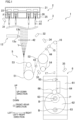
- the spun yarn winding system 1 includes spinning apparatuses 2 (see FIG. 1 ), spun yarn take-up winders 3 provided to correspond to the respective spinning apparatuses 2, and an integrated controller 4 (as shown in FIG. 2 ).
- FIG. 1 shows one spinning apparatus 2 and one spun yarn take-up winder 3 provided to correspond to that spinning apparatus 2.
- Each spinning apparatus 2 is configured to spin out yarns Y made of synthetic fibers.
- the spun yarn take-up winders 3 are aligned in the left-right direction. Above each spun yarn take-up winder 3, a corresponding spinning apparatus 2 is provided.
- Each spun yarn take-up winder 3 is configured to take up yarns Y spun out from the corresponding spinning apparatus 2, to wind the yarns Y onto the respective bobbins B, and to form packages P.
- the integrated controller 4 controls the spun yarn take-up winders 3 integrally.
- each spinning apparatus 2 mainly includes a heating box 21 and a cooling box 25.
- the cooling box 25 is provided below the heating box 21.
- the heating box 21 is heated to have a temperature equal to or higher than the melting point of polymer.
- spinning packs 22 are attached to each spinning pack 22 .
- molten polymer is supplied through a polymer path (not illustrated) formed inside the heating box 21.
- Each spinning pack 22 spins out the molten polymer downward as filaments f.
- cooling cylinders 26 each of which is formed of a filter are provided inside the cooling box 25.
- the cooling cylinders 26 are provided to correspond to the respective spinning packs 22 attached to the heating box 21.
- the filaments f spun out from each spinning pack 22 pass through the inside of the corresponding cooling cylinder 26 downward.
- cooling air is pressure-supplied through an unillustrated duct.
- the cooling air having been pressure-supplied into the cooling box 25 is then pressure-supplied into the cooling cylinder 26 formed of a filter. As a result, the filaments F passing through the inside of the cooling cylinder 26 are cooled and solidified.
- each spun yarn take-up winder 3 mainly includes oil supply guides 11, a cutting suction device 13, a drawing unit 5, an interlacing device 15, a guide roller 16, a yarn information acquisition unit 17, a winding device 6, and cameras 31 to 35.
- each spun yarn take-up winder 3 further includes a winding controller 18.
- the oil supply guides 11 are provided below the spinning apparatus 2.
- the oil supply guides 11 are provided to correspond to the respective cooling cylinders 26 provided at the cooling box 25 of the spinning apparatus 2.
- Each oil supply guide 11 is provided to correspond to a single yarn Y formed of filaments f.
- Each oil supply guide 11 supplies oil to a bundle of filaments f.
- a yarn regulating guide 41 is provided below each oil supply guide 11.
- the yarn regulating guide 41 is provided on the downstream side of the oil supply guide 11 in the running direction of the yarns Y (i.e., the downward direction) .
- oil is applied to the yarn Y (filaments F) whose yarn path is restricted by the yarn regulating guide 41.
- the cutting suction device 13 mainly includes a cutter 13a capable of cutting the yarns Y and an aspirator 13b configured to suck the yarns Y cut by the cutter 13a.
- the cutter 13a and the aspirator 13b are configured to be movable in an arrangement direction of the yarns Y (i.e., in the left-right direction). As the cutter 13a and the aspirator 13b are moved in the left-right direction, the yarns Y are cut by the cutter 13a.
- a position where the yarns Y are cut by the cutter 13a is between the oil supply guides 11 and a later-described godet roller 51 of the drawing unit 5 in the running direction of the yarns Y (i.e., the downward direction).
- the yarns Y having been cut by the cutter 13a are then sucked and held by the aspirator 13b.
- a yarn regulating guide 42 is provided below the cutting suction device 13.
- the yarn regulating guide 42 is provided between a cutting position of the yarns Y where the cutting suction device 13 cuts the yarns and the later-described godet roller 51 of the drawing unit 5.
- the yarn regulating guide 42 regulates the movement of the yarns Y in the arrangement direction thereof.
- the drawing unit 5 mainly includes two godet rollers 51 and 52 and two separate rollers 53 and 54.
- the godet roller 52 is provided on the downstream side of the godet roller 51 in the running direction of the yarns Y.
- the godet roller 51 is paired with the separate roller 53 provided above the godet roller 51.
- the godet roller 52 is paired with the separate roller 54 provided below the godet roller 52.
- a yarn regulating guide 43 is provided between the godet roller 51 and the godet roller 52.
- the yarn regulating guide 43 regulates the movement of the yarns Y in the arrangement direction thereof.
- Each of the two godet rollers 51 and 52 is a drive roller driven by a drive motor (not illustrated) .
- Each of the two separate rollers 53 and 54 is a drive roller driven by a drive motor (not illustrated).
- the rotational axes of the godet rollers 51 and 52 and the separate rollers 53 and 54 are in parallel to one another.
- the godet rollers 51 and 52 and the separate rollers 53 and 54 are disposed so that the rotational axes of these rollers are in parallel to the front-rear direction.
- the yarns Y having been sent to the drawing unit 5 are wound onto the upstream godet roller 51 and the upstream separate roller 53 more than once, and are then wound onto the downstream godet roller 52 and the downstream separate roller 54 more than once.
- a yarn regulating guide 44 is provided on the downstream side of the godet roller 52 of the drawing unit 5 in the running direction of the yarns Y.
- the yarn regulating guide 44 regulates the movement of the yarns Y in the arrangement direction thereof.
- the interlacing device 15 is provided between the godet roller 52 of the drawing unit 5 and the guide roller 16.
- the interlacing device 15 is provided on the downstream side of the yarn regulating guide 44 in the running direction of the yarns Y.
- the interlacing device 15 is configured to generate a swirling flow in a running space (not illustrated) of the yarns Y by blowing out air from a fluid ejection nozzle (not illustrated).
- a fluid ejection nozzle not illustrated
- the yarn information acquisition unit 17 is constituted by, e.g., reflective optical sensors each of which includes a light emitter and light receiver (both are not illustrated).
- the optical sensors are provided to correspond to the respective yarns Y sent from the guide roller 16.
- Each optical sensor is configured to emit light from the light emitter (not illustrated) toward the yarn path of the yarn Y, and to receive the light reflected by the yarn Y running in the yarn path by means of the light receiver (not illustrated).
- the amount of light detected by the optical sensor is different between a case where the yarn Y exists in the yarn path and a case where the yarn Y does not exist in the yarn path.
- the yarn information acquisition unit 17 outputs information of the light amount indicating that there is no yarn Y in the yarn path, as a yarn cutting signal (equivalent to a predetermined signal of the present invention) indicating that yarn cutting has occurred.
- the winding device 6 mainly includes a main body frame 61, a turret 62, two bobbin holders 63, fulcrum guides 64, traverse guides 65, and a contact roller 66.
- the turret 62 is supported by the main body frame 61.
- the turret 62 is disc-shaped.
- the turret 62 is rotatable about a rotational axis extending along the front-rear direction.
- the fulcrum guides 64 and the traverse guides 65 are attached to the main body frame 61.
- the fulcrum guides 64 are provided above the bobbin holder 63 at the winding position.
- the traverse guides 65 are provided above the fulcrum guides 64.
- the fulcrum guides 64 and the traverse guides 65 are provided to correspond to the respective bobbins B.
- Each traverse guide 65 is configured to traverse the yarn Y threaded to the corresponding fulcrum guide 64.
- the winding controller 18 includes members such as a CPU, a ROM, and a RAM.
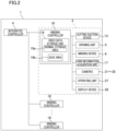
- the winding controller 18 is configured to control components of the spun yarn take-up winder 3, such as the cutting suction device 13 (see FIG. 2 ).
- the winding controller 18 is electrically connected to the yarn information acquisition unit 17 and the cameras 31 to 35 (imaging devices of the present invention).
- the winding controller 18 is electrically connected to an operating unit 37 and a display device 38.
- the operating unit 37 includes at least one of a keyboard, a mouse, and a touch panel, for example.
- the display device 38 is, for example, a display.
- the winding controller 18 includes a video data storage unit 19.
- the winding controller 18 is electrically connected to the integrated controller 4 (as shown in FIG. 2 ), and communicates with the integrated controller 4.
- the camera 31 is provided in the vicinity of the cooling box 25 of the spinning apparatus 2.
- the camera 31 is able to take videos of the oil supply guides 11 and the yarn regulating guide 41, in addition to the yarns Y.
- the camera 31 is able to take videos of phenomena that may occur at these imaging targets, such as yarn cutting, entangled yarn running, filament transfer, filament detachment, derailing from the guide, yarn split, yarn shaking, yarn vibration, insufficient bundling, oil scattering, oil droplets, and fluff generation.
- the entangled yarn running is a problem that a yarn Y makes contact with another yarn Y for some reason (e.g., shaking) and the yarn Y and the another yarn Y are entangled and run.
- the filament transfer is a problem that at least one filament of one yarn Y moves to another yarn Y and runs.
- the filament detachment is a problem that a filament f in a yarn Y is cut and detached from the yarn Y.
- the camera 32 is provided between the oil supply guides 11 and the drawing unit 5.
- the camera 32 is able to take a video of the yarn regulating guide 42 in addition to the yarns Y.
- the camera 32 is able to take videos of phenomena that may occur at these imaging targets, such as yarn cutting, entangled yarn running, derailing from the guide, yarn shaking, yarn vibration, insufficient bundling, oil scattering, oil droplets, and fluff generation.
- the camera 33 is provided between the godet roller 51 and the godet roller 52.
- the camera 33 is able to take a video of the yarn regulating guide 43 in addition to the yarns Y.
- the camera 33 is able to take videos of phenomena that may occur at these imaging targets, such as yarn cutting, entangled yarn running, derailing from the guide, yarn shaking, yarn vibration, and fluff generation.
- the camera 34 is provided in the vicinity of the interlacing device 15.
- the camera 34 is able to take videos of the interlacing device 15 and the yarn regulating guide 44.
- the camera 34 is able to take videos of phenomena that may occur at these imaging targets, such as yarn cutting, entangled yarn running, derailing from the guide, yarn shaking, yarn vibration, fluff generation, and insufficient turning of filaments.
- the camera 35 is provided in the vicinity of the winding device 6.
- the cameras 35 is able to take a video of the winding device 6.
- the camera 35 is able to take videos of phenomena that may occur at these imaging targets, such as yarn cutting, entangled yarn running, derailing from the guide, yarn shaking, yarn vibration, fluff generation, a change of the package shape, and malfunction of the winding device.
- the winding controller 18 executes a command signal generation process of generating a command signal by which execution of a yarn cutting process necessitated by the occurrence of the yarn cutting is instructed.
- the cutting suction device 13 executes cutting and sucking of the yarns Y.
- the winding controller 18 executes a data sampling process of sampling part of the video data stored in the normal storage area 19a of the video data storage unit 19.
- the winding controller 18 stores the video data sampled in the data sampling process in the save area 19b of the video data storage unit 19.
- the winding controller 18 executes the data sampling process when receiving, from the yarn information acquisition unit 17, the yarn cutting signal indicating that yarn cutting has occurred.
- the winding controller 18 executes the data sampling process when the command signal generation process is executed.
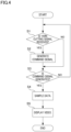
- the following will describe an example of a control flow of the winding controller 18, with reference to a flow chart shown in FIG. 4 .
- the process shown in FIG. 4 is executed while the winding device 6 is winding the yarn Y onto the bobbin B in the winding process.
- the winding controller 18 continuously executes an image taking process by means of the cameras 31 to 35, no matter whether the winding process is being executed at the winding device 6.
- the winding controller 18 executes a storage process of storing video data of the videos taken in the image taking process in the normal storage area 19a of the video data storage unit 19.
- the winding controller 18 displays videos taken in the image taking process on the display device 38 real time.
- the winding controller 18 determines whether a yarn cutting signal indicating that at least one yarn Y of plural yarns Y has been cut is received from the yarn information acquisition unit 17 (S1). When the yarn cutting signal has been received (YES in S1), the winding controller 18 generates a command signal which instructs the cutting suction device 13 to perform a yarn cutting process of cutting the yarns Y (S2; command signal generation process) . On the other hand, when the yarn cutting signal has not been received (NO in S1), the above-described S2 is omitted and the flow proceeds to S3.
- the winding controller 18 determines whether the command signal has been generated (S3).
- the winding controller 18 samples part of the video data stored in the normal storage area 19a of the video data storage unit 19 in the storage process (S4; data sampling process).
- the winding controller 18 samples a set of video data corresponding to a video taken during the predetermined range R (see FIG. 3 ) from the video data stored in the normal storage area 19a of the video data storage unit 19.
- the winding controller 18 then stores the video data sampled in the data sampling process in the save area 19b of the video data storage unit 19.
- the command signal has not been generated (NO in S3), the flow goes back to S1.
- a video corresponding to the video data stored in the save area 19b is automatically displayed on the display device 38.
- the disclosure is not limited to this arrangement.
- the winding controller 18 may display the video on the display device 38.
- the spun yarn winding system 1 of the present embodiment includes the spun yarn take-up winder 3 configured to take up the yarns Y spun out from the spinning apparatus 2 and wind the yarns Y onto the bobbins B, and further includes, at different positions on the yarn path from the spinning apparatus 2 to the spun yarn take-up winder 3, the cameras 31 to 35 capable of taking videos of the yarns Y, the video data storage unit 19 configured to store the video data of the videos taken by the cameras 31 to 35, the yarn information acquisition unit 17 capable of acquiring information regarding the state of the yarns Y on the yarn path, and the winding controller 18.
- videos of the yarns Y can be taken by the cameras 31 to 35, at plural parts of the yarn path from the spinning apparatus 2 to the spun yarn take-up winder 3.
- the operator is therefore able to know the state of the yarns Y at plural parts of the yarn path by means of the videos taken by the cameras 31 to 35.
- the operator is able to check the state of the yarns Y at plural parts of the yarn path based on the videos and analyze why the yarn cutting occurred.
- the operator is able to check the part of the yarn path where the yarn cutting occurred with reference to the videos and analyze why the yarn cutting occurred based on the observation.
- videos of the yarns Y taken by the cameras 31 to 35 can be obtained as information for analyzing the reason of the yarn cutting.
- the yarn information acquisition unit 17 is able to obtain information regarding the occurrence of yarn cutting.
- the winding controller 18 samples, from the video data stored in the normal storage area 19a, a set of video data which corresponds to a video taken during the predetermined range R that includes at least a time before a time of receiving the yarn cutting signal and is set on the basis of the time of receiving the yarn cutting signal.
- the spun yarn winding system 1 of the present embodiment further includes the cutting suction device 13 capable of cutting and sucking the yarns Y and the yarn information acquisition unit 17 is capable of acquiring information regarding the occurrence of yarn cutting for the yarns Y.
- the winding controller 18 executes the command signal generation process of generating a command signal by which execution of a yarn cutting process of cutting and sucking the yarns Y by the cutting suction device 13 is instructed. Furthermore, the winding controller 18 executes the data sampling process when the command signal generation process is executed.
- the control is simplified as compared to a case where the data sampling process is executed when a signal indicating the occurrence of yarn cutting is received from the yarn information acquisition unit 17.
- the cameras 31 to 35 are able to take videos of the components of the spun yarn winding system 1.
- the arrangement allows the operator to check, based on the videos, the operation of each component and the state of the yarns Y at each component, in addition to the state of the yarns Y. This allows the operator to further reliably analyze the reason of the yarn cutting. In this way, according to this arrangement, videos of the components can be obtained as information for analyzing the reason of the yarn cutting.
- the winding controller 18 samples part of the video data stored in the normal storage area 19a of the video data storage unit 19 and stores the sampled video data in the save area 19b.
- the disclosure is not limited to this arrangement.
- the winding controller 18 may not store the sampled video data in the save area 19b.
- the winding controller 18 may sample video data in the data sampling process and may display a video corresponding to that video data on the display device 38.
- the yarn information acquisition unit 17 is able to obtain information regarding the occurrence of yarn cutting, the disclosure is not limited to this arrangement.
- the yarn information acquisition unit 17 may be differently arranged as long as the unit is able to obtain information regarding the state of the yarns Y in the yarn path.
- the yarn information acquisition unit 17 may be able to obtain information regarding an indication of yarn cutting.
- the yarn information acquisition unit 17 may be able to obtain information regarding the magnitude of the tension of the yarns Y.
- yarn swing occurs when the tension of the yarns Y becomes small to some degree. The smaller the tension of the yarns Y is, the more the yarns Y swing. Strong yarn swing is an indication of yarn cutting. Furthermore, the occurrence of yarn cutting is detectable based on a change of the tension of the yarns Y.
- the winding controller 18 when receiving a predetermined signal indicating that the magnitude of the tension of the yarns Y is equal to or less than a predetermined threshold, the winding controller 18 samples a set of video data corresponding to a video taken in a predetermined range that is set on the basis of a time at which the predetermined signal was received, from the video data stored in the normal storage area 19a of the video data storage unit 19.
- the threshold is a value at which the magnitude of the tension of the yarns Y indicates no occurrence of yarn cutting.
- information regarding the magnitude of the tension of the yarns Y obtained by the yarn information acquisition unit 17 indicates the occurrence of yarn swing that is an indication of yarn cutting.
- the data sampling process it is possible to sample a set of video data corresponding to a video showing yarn swing before the occurrence of yarn cutting. It is therefore easy to obtain information for reliably analyzing the indication of the yarn cutting.
- the yarn information acquisition unit 17 may be able to obtain information regarding the static electricity amount of the yarns Y.
- Strong yarn swing is an indication of yarn cutting.
- the occurrence of yarn cutting is detectable based on a change of the static electricity amount of the yarns Y.
- the winding controller 18 when receiving a predetermined signal indicating that the static electricity capacity of the yarns Y is equal to or more than a predetermined threshold, the winding controller 18 samples a set of video data corresponding to a video taken in a predetermined range that is set on the basis of a time at which the predetermined signal was received, from the video data stored in the normal storage area 19a of the video data storage unit 19.
- the threshold is a value at which the static electricity amount of the yarns Y indicates no occurrence of yarn cutting.
- information regarding the static electricity amount of the yarns Y obtained by the yarn information acquisition unit 17 indicates the occurrence of yarn swing that is an indication of yarn cutting.
- the data sampling process it is possible to sample a set of video data corresponding to a video showing yarn swing before the occurrence of yarn cutting. It is therefore easy to obtain information for reliably analyzing the indication of the yarn cutting.
- the winding controller 18 executes the data sampling process when the command signal generation process of generating the command signal by which the execution of the yarn cutting process is instructed is executed.
- the disclosure is not limited to this arrangement.
- the winding controller 18 may execute the data sampling process when receiving, from the yarn information acquisition unit 17, a signal indicating that yarn cutting has occurred.
- the embodiment above describes a case where videos taken by the cameras 31 to 35 are displayed on the display device 38 that is electrically connected to the winding controller 18.
- the disclosure is not limited to this arrangement.
- the winding controller 18 may display videos on a display of a terminal (e.g., a mobile terminal such as a tablet terminal) connected to the winding controller 18 over a network such as a LAN or the Internet.
- the winding controller 18 may store videos in, for example, a recording medium such as an SD card or a cloud server.
Landscapes
- Engineering & Computer Science (AREA)
- Mechanical Engineering (AREA)
- Textile Engineering (AREA)
- Quality & Reliability (AREA)
- Filamentary Materials, Packages, And Safety Devices Therefor (AREA)
- Spinning Methods And Devices For Manufacturing Artificial Fibers (AREA)
Abstract
Description
- The present invention relates to a spun yarn winding system including a spun yarn take-up winder configured to wind yarns spun out from a spinning apparatus.
- Patent Literature 1 (
Japanese Laid-Open Patent Publication 2021-050440 - When yarn cutting occurs, the above-described spun yarn winding system needs to temporarily stop the spun yarn take-up winder and to perform yarn threading for components such as the godet rollers, the fulcrum guide, and the bobbin. On this account, the production efficiency of the yarns is deteriorated when the yarn cutting occurs. To suppress the occurrence of yarn cutting, enabling the analysis of an indication of yarn cutting and a reason of yarn cutting has been demanded. However, because no means is available for acquiring information necessary for the analysis of an indication of yarn cutting and a reason of yarn cutting, it has been difficult to analyze an indication of yarn cutting and a reason of yarn cutting.
- An object of the present invention is to provide a spun yarn winding system which is capable of obtaining information used for analyzing an indication of yarn cutting and a reason of yarn cutting.
- According to a first aspect of the invention, a spun yarn winding system comprises a spun yarn take-up winder configured to take up a yarn spun out from a spinning apparatus and wind the yarn onto a bobbin, the spun yarn winding system further comprising: imaging devices which are able to take a video of the yarn Y at different positions on a yarn path from the spinning apparatus to the spun yarn take-up winder; a storage unit which is configured to store video data of the video taken by the imaging devices; a yarn information acquisition unit which is capable of acquiring information regarding a state of the yarn on the yarn path; and a controller. When receiving a predetermined signal indicating the information regarding the state of the yarn from the yarn information acquisition unit, the controller executes a data sampling process of sampling video data corresponding to a video taken during a predetermined range that is set on the basis of a time at which the predetermined signal is received, from the video data stored in the storage unit.
- According to this aspect of the present invention, a video of the yarn can be taken by the imaging devices, at plural parts of the yarn path from the spinning apparatus to the spun yarn take-up winder. The operator is therefore able to know the state of the yarn at plural parts of the yarn path by means of the video taken by the imaging devices. On this account, when yarn cutting or an indication of yarn cutting occurs, an operator is able to check the state of the yarn at plural parts of the yarn path based on the video and analyze why the yarn cutting or the indication thereof occurred. For example, the operator is able to check the part of the yarn path where the yarn cutting or the indication thereof occurred with reference to the video and analyze why the yarn cutting or the indication thereof occurred based on the observation. In this way, according to the aspect of the present invention, the video of the yarn taken by the imaging devices can be obtained as information for analyzing the reason of the yarn cutting or the indication thereof. With the aspect of the present invention, furthermore, part of the video data stored in the storage unit can be sampled in accordance with the state of the yarn on the yarn path. This makes it possible to sample information required for analyzing a reason of yarn cutting or an indication thereof from the video data stored in the storage unit. On this account, the operator is able to obtain the information without needing labor to find a required video from the videos corresponding to the video data stored in the storage unit.
- According to a second aspect of the invention, the spun yarn winding system is arranged so that the yarn information acquisition unit is capable of acquiring information regarding occurrence of yarn cutting, and in the data sampling process, upon receiving the predetermined signal indicating that the yarn cutting has occurred, the controller samples, from the video data stored in the storage unit, video data corresponding to a video which is taken during the predetermined range that includes at least a time before the time of receiving the predetermined signal and is set on the basis of the time of receiving the predetermined signal.
- This aspect of the present invention makes it possible to sample video data in accordance with the occurrence of yarn cutting and to obtain a video for checking the state of the yarn at the occurrence of the yarn cutting. It is therefore easy to obtain information for reliably analyzing a reason of yarn cutting.
- According to a third aspect of the invention, the spun yarn winding system is arranged so that the yarn information acquisition unit is capable of acquiring information regarding magnitude of tension of the yarn, in the data sampling process, when receiving the predetermined signal indicating that the magnitude of the tension of the yarn is equal to or smaller than a predetermined threshold, the controller samples video data corresponding to a video taken in the predetermined range that is set on the basis of a time at which the predetermined signal was received, from the video data stored in the storage unit, and the predetermined threshold is a value at which the magnitude of the tension of the yarn indicates no occurrence of yarn cutting.
- According to the aspect of the present invention, information regarding the magnitude of the tension of the yarn obtained by the yarn information acquisition unit indicates the occurrence of yarn swing that is an indication of yarn cutting. In the data sampling process, it is possible to sample a set of video data corresponding to a video showing yarn swing before the occurrence of yarn cutting. It is therefore easy to obtain information for reliably analyzing the indication of the yarn cutting.
- According to a fourth aspect of the invention, the spun yarn winding system is arranged so that the yarn information acquisition unit is capable of acquiring information regarding an amount of static electricity of the yarn, in the data sampling process, when receiving the predetermined signal indicating that the amount of the static electricity of the yarn is equal to or larger than a predetermined threshold, the controller samples video data corresponding to a video taken in the predetermined range that is set on the basis of a time at which the predetermined signal was received, from the video data stored in the storage unit, and the predetermined threshold is a value at which the amount of the static electricity of the yarn indicates no occurrence of yarn cutting.
- According to the aspect of the present invention, information regarding the static electricity amount of the yarn obtained by the yarn information acquisition unit indicates the occurrence of yarn swing that is an indication of yarn cutting. In the data sampling process, it is possible to sample a set of video data corresponding to a video showing yarn swing before the occurrence of yarn cutting. It is therefore easy to obtain information for reliably analyzing the indication of the yarn cutting.
- According to a fifth aspect of the invention, the spun yarn winding system is arranged so that the spun yarn take-up winder is capable of taking up yarns spun out from the spinning apparatus and winding the yarns onto bobbins, respectively, the spun yarn winding system further comprising a cutting suction device which is capable of cutting and sucking the yarns, each of the imaging devices is capable of taking a video of the yarns, the yarn information acquisition unit is capable of acquiring information regarding occurrence of yarn cutting of each of the yarns, when receiving the predetermined signal indicating that at least one of the yarns has been cut from the yarn information acquisition unit, the controller executes a command signal generation process of generating a command signal by which execution of a yarn cutting process of cutting and sucking the yarns by the cutting suction device is instructed, and when the command signal generation process is executed, the controller executes the data sampling process.
- According to this aspect of the present invention, because the data sampling process is executed by utilizing generation of the command signal by which execution of the yarn cutting process of cutting and sucking the yarns by the cutting suction device is instructed, the control is simplified as compared to a case where the data sampling process is executed when a signal indicating the occurrence of yarn cutting is received from the yarn information acquisition unit.
- According to a sixth aspect of the invention, the spun yarn winding system is arranged so that at least one imaging device among the imaging devices is capable of taking an image of at least one component of the spun yarn winding system.
- According to this aspect of the present invention, when yarn cutting or an indication of yarn cutting occurs, the operator is allowed to check, based on the video, the operation of each component and the state of the yarns at each component, in addition to the state of the yarns. This allows the operator to further reliably analyze the reason of the yarn cutting or the indication of yarn cutting. In this way, according to the aspect of the present invention, a video of each component can be obtained as information for analyzing the reason of the yarn cutting or the indication thereof.
- According to a seventh aspect of the invention, the spun yarn winding system further comprises a display device which is capable of displaying a video taken by the imaging devices.
- This aspect of the present invention allows the operator to analyze the reason of yarn cutting or an indication thereof with reference to the video displayed on the display device.
-
-
FIG. 1 is a front elevation of one spun yarn take-up winder of a spun yarn winding system of an embodiment of the present invention. -
FIG. 2 is a block diagram showing an electric structure of the spun yarn winding system. -
FIG. 3 is a drawing used for explaining a predetermined range for sampling in a data sampling process. -
FIG. 4 is a flowchart of control performed by a winding controller. - The following will describe a preferred embodiment of the present invention with reference to figures. Hereinafter, the directions shown in
FIG. 1 will be referred to as an up-down direction, a left-right direction, and a front-back direction, respectively. The up-down direction is a vertical direction in which the gravity acts. The left-right direction is orthogonal to the up-down direction, and is a direction in which spun yarn take-upwinders 3 described later are aligned. The front-rear direction is a direction orthogonal to both the up-down direction and the left-right direction. - The following will outline a spun
yarn winding system 1 related to the present embodiment, with reference toFIG. 1 to FIG. 2 . The spunyarn winding system 1 includes spinning apparatuses 2 (seeFIG. 1 ), spun yarn take-up winders 3 provided to correspond to therespective spinning apparatuses 2, and an integrated controller 4 (as shown inFIG. 2 ).FIG. 1 shows onespinning apparatus 2 and one spun yarn take-up winder 3 provided to correspond to that spinningapparatus 2. Eachspinning apparatus 2 is configured to spin out yarns Y made of synthetic fibers. The spun yarn take-upwinders 3 are aligned in the left-right direction. Above each spun yarn take-up winder 3, acorresponding spinning apparatus 2 is provided. Each spun yarn take-upwinder 3 is configured to take up yarns Y spun out from thecorresponding spinning apparatus 2, to wind the yarns Y onto the respective bobbins B, and to form packages P. The integratedcontroller 4 controls the spun yarn take-up winders 3 integrally. - As shown in
FIG. 1 , eachspinning apparatus 2 mainly includes aheating box 21 and acooling box 25. Thecooling box 25 is provided below theheating box 21. - The
heating box 21 is heated to have a temperature equal to or higher than the melting point of polymer. To theheating box 21,spinning packs 22 are attached. To each spinningpack 22, molten polymer is supplied through a polymer path (not illustrated) formed inside theheating box 21. Each spinningpack 22 spins out the molten polymer downward as filaments f. As the filaments f spun out from each spinningpack 22 are bundled at a later-describedoil supply guide 11, a single yarn Y is formed. - Inside the
cooling box 25, coolingcylinders 26 each of which is formed of a filter are provided. The coolingcylinders 26 are provided to correspond to the respective spinning packs 22 attached to theheating box 21. The filaments f spun out from each spinningpack 22 pass through the inside of thecorresponding cooling cylinder 26 downward. To thecooling box 25, cooling air is pressure-supplied through an unillustrated duct. The cooling air having been pressure-supplied into thecooling box 25 is then pressure-supplied into thecooling cylinder 26 formed of a filter. As a result, the filaments F passing through the inside of thecooling cylinder 26 are cooled and solidified. - As shown in
FIG. 1 , each spun yarn take-upwinder 3 mainly includes oil supply guides 11, a cuttingsuction device 13, adrawing unit 5, an interlacingdevice 15, aguide roller 16, a yarninformation acquisition unit 17, a windingdevice 6, andcameras 31 to 35. As shown inFIG. 2 , each spun yarn take-upwinder 3 further includes a windingcontroller 18. - The oil supply guides 11 are provided below the
spinning apparatus 2. The oil supply guides 11 are provided to correspond to therespective cooling cylinders 26 provided at thecooling box 25 of thespinning apparatus 2. Eachoil supply guide 11 is provided to correspond to a single yarn Y formed of filaments f. Eachoil supply guide 11 supplies oil to a bundle of filaments f. Below eachoil supply guide 11, ayarn regulating guide 41 is provided. To put it differently, theyarn regulating guide 41 is provided on the downstream side of theoil supply guide 11 in the running direction of the yarns Y (i.e., the downward direction) . In theoil supply guide 11, oil is applied to the yarn Y (filaments F) whose yarn path is restricted by theyarn regulating guide 41. - The cutting
suction device 13 mainly includes acutter 13a capable of cutting the yarns Y and anaspirator 13b configured to suck the yarns Y cut by thecutter 13a. Thecutter 13a and theaspirator 13b are configured to be movable in an arrangement direction of the yarns Y (i.e., in the left-right direction). As thecutter 13a and theaspirator 13b are moved in the left-right direction, the yarns Y are cut by thecutter 13a. A position where the yarns Y are cut by thecutter 13a is between the oil supply guides 11 and a later-describedgodet roller 51 of thedrawing unit 5 in the running direction of the yarns Y (i.e., the downward direction). The yarns Y having been cut by thecutter 13a are then sucked and held by theaspirator 13b. - Below the cutting
suction device 13, ayarn regulating guide 42 is provided. In the running direction of the yarns Y (i.e., the downward direction), theyarn regulating guide 42 is provided between a cutting position of the yarns Y where the cuttingsuction device 13 cuts the yarns and the later-describedgodet roller 51 of thedrawing unit 5. Theyarn regulating guide 42 regulates the movement of the yarns Y in the arrangement direction thereof. - To the
drawing unit 5, the yarns Y to which the oil has been applied at the oil supply guides 11 are sent. Thedrawing unit 5 mainly includes twogodet rollers separate rollers godet roller 52 is provided on the downstream side of thegodet roller 51 in the running direction of the yarns Y. Thegodet roller 51 is paired with theseparate roller 53 provided above thegodet roller 51. Thegodet roller 52 is paired with theseparate roller 54 provided below thegodet roller 52. Between thegodet roller 51 and thegodet roller 52, ayarn regulating guide 43 is provided. Theyarn regulating guide 43 regulates the movement of the yarns Y in the arrangement direction thereof. - Each of the two
godet rollers separate rollers godet rollers separate rollers godet rollers separate rollers drawing unit 5 are wound onto theupstream godet roller 51 and the upstreamseparate roller 53 more than once, and are then wound onto thedownstream godet roller 52 and the downstreamseparate roller 54 more than once. - The
upstream godet roller 51 is heated to a drawable temperature at which the yarns Y can be drawn (e.g., 90 degrees centigrade). Thedownstream godet roller 52 is heated to a temperature at which the drawn yarns Y can be thermally set (e.g., 120 degrees centigrade). Thegodet roller 52 rotates at a higher rotation speed than thegodet roller 51 on the upstream side. On this account, the yarns Y preliminarily heated at theupstream godet roller 51 are drawn between theupstream godet roller 51 an dtdownstream godet roller 52. The drawn yarns Y are thermally set by thegodet roller 52. The yarns Y drawn at thedrawing unit 5 are wound onto theguide roller 16. - On the downstream side of the
godet roller 52 of thedrawing unit 5 in the running direction of the yarns Y, ayarn regulating guide 44 is provided. Theyarn regulating guide 44 regulates the movement of the yarns Y in the arrangement direction thereof. - The interlacing
device 15 is provided between thegodet roller 52 of thedrawing unit 5 and theguide roller 16. The interlacingdevice 15 is provided on the downstream side of theyarn regulating guide 44 in the running direction of the yarns Y. The interlacingdevice 15 is configured to generate a swirling flow in a running space (not illustrated) of the yarns Y by blowing out air from a fluid ejection nozzle (not illustrated). As a result, the filaments f constituting one yarn Y are turned and entangled with one another. Consequently, the filaments f of the yarn Y are bundled. - The
guide roller 16 is a drive roller driven by a driving motor (not illustrated). Theguide roller 16 is disposed so that its rotational axis is in parallel to the front-rear direction. Onto theguide roller 16, the yarns Y drawn at thedrawing unit 5 are wound. Theguide roller 16 sends the yarns Y to the windingdevice 6. - The yarn
information acquisition unit 17 is provided between theguide roller 16 and the windingdevice 6 in the running direction of the yarns Y. The yarninformation acquisition unit 17 is capable of acquiring information regarding the state of the yarns Y in the yarn path sent from theguide roller 16. The yarninformation acquisition unit 17 sends the acquired information to a winding controller 18 (seeFIG. 2 ). The yarninformation acquisition unit 17 of the present embodiment is capable of acquiring information regarding the occurrence of yarn cutting of each of the yarns Y. - The yarn
information acquisition unit 17 is constituted by, e.g., reflective optical sensors each of which includes a light emitter and light receiver (both are not illustrated). The optical sensors are provided to correspond to the respective yarns Y sent from theguide roller 16. Each optical sensor is configured to emit light from the light emitter (not illustrated) toward the yarn path of the yarn Y, and to receive the light reflected by the yarn Y running in the yarn path by means of the light receiver (not illustrated). On this account, the amount of light detected by the optical sensor is different between a case where the yarn Y exists in the yarn path and a case where the yarn Y does not exist in the yarn path. When yarn cutting occurs, the amount of the detected light indicates that there is no yarn Y in the yarn path. When yarn cutting occurs, the yarninformation acquisition unit 17 outputs information of the light amount indicating that there is no yarn Y in the yarn path, as a yarn cutting signal (equivalent to a predetermined signal of the present invention) indicating that yarn cutting has occurred. - The yarn
information acquisition unit 17 may include transmissive optical sensors instead of the reflective optical sensors. That is to say, the unillustrated light emitter may be provided to oppose the unillustrated light receiver over the yarn Y in the left-right direction. - To the winding
device 6, the yarns Y having been wound onto theguide roller 16 are sent. The windingdevice 6 mainly includes amain body frame 61, aturret 62, twobobbin holders 63, fulcrum guides 64, traverse guides 65, and acontact roller 66. - The
turret 62 is supported by themain body frame 61. Theturret 62 is disc-shaped. Theturret 62 is rotatable about a rotational axis extending along the front-rear direction. To theturret 62, the twobobbin holders 63 are attached. - Each of the two
bobbin holders 63 is rotationally driven by a motor (not illustrated). The rotational axes of the twobobbin holders 63 are in parallel to each other. The twobobbin holders 63 are disposed so that their axes are in parallel to the front-rear direction. To eachbobbin holder 63, bobbins B are attached to be aligned in the axial direction. As eachbobbin holder 63 rotates, the bobbins B attached to thebobbin holder 63 rotate together with thebobbin holder 63. - As the
turret 62 supporting the twobobbin holders 63 rotates, the positions of the twobobbin holders 63 are switched between a winding position (upper position inFIG. 1 ) and a retracted position (lower position inFIG. 1 ). As such, theturret 62 is provided to switch thebobbin holders 63 by which the yarns Y are wound. - The fulcrum guides 64 and the traverse guides 65 are attached to the
main body frame 61. The fulcrum guides 64 are provided above thebobbin holder 63 at the winding position. The traverse guides 65 are provided above the fulcrum guides 64. The fulcrum guides 64 and the traverse guides 65 are provided to correspond to the respective bobbins B. Eachtraverse guide 65 is configured to traverse the yarn Y threaded to thecorresponding fulcrum guide 64. - The yarns Y sent from the
guide roller 16 are threaded to the respective fulcrum guides 64. The yarns Y are then wound onto bobbins B attached to thebobbin holder 63 at the winding position, respectively, while being traversed about the corresponding fulcrum guides 64 in the axial direction of the bobbins B by the traverse guides 65. As a result, packages P are formed around the respective bobbins B. When the yarns are being wound, as thecontact roller 66 in contact with the outer circumferential surface of each package P rotates while applying a predetermined contact pressure to each package P, the shape of the package P is adjusted. - The winding
controller 18 includes members such as a CPU, a ROM, and a RAM. The windingcontroller 18 is configured to control components of the spun yarn take-upwinder 3, such as the cutting suction device 13 (seeFIG. 2 ). The windingcontroller 18 is electrically connected to the yarninformation acquisition unit 17 and thecameras 31 to 35 (imaging devices of the present invention). The windingcontroller 18 is electrically connected to anoperating unit 37 and adisplay device 38. The operatingunit 37 includes at least one of a keyboard, a mouse, and a touch panel, for example. Thedisplay device 38 is, for example, a display. The windingcontroller 18 includes a videodata storage unit 19. The windingcontroller 18 is electrically connected to the integrated controller 4 (as shown inFIG. 2 ), and communicates with theintegrated controller 4. - The five
cameras 31 to 35 are able to take videos of the yarns Y at different positions on the yarn path from thespinning apparatus 2 to the spun yarn take-upwinder 3. The number of the cameras is not restricted to five. The number of the cameras may be determined at will as long as the number is two or more. Each of thecameras 31 to 35 is able to take a video of the yarns Y running on the yarn path. In the present embodiment, thecameras 31 to 35 are able to take videos of the components of the spunyarn winding system 1, in addition to the yarns Y. Alternatively, thecameras 31 to 35 may be able to take videos of only the yarns Y. Alternatively, at least one of thecameras 31 to 35 may be able to take videos of the components of the spunyarn winding system 1 in addition to the yarns Y. - The
camera 31 is provided in the vicinity of thecooling box 25 of thespinning apparatus 2. Thecamera 31 is able to take videos of the oil supply guides 11 and theyarn regulating guide 41, in addition to the yarns Y. Thecamera 31 is able to take videos of phenomena that may occur at these imaging targets, such as yarn cutting, entangled yarn running, filament transfer, filament detachment, derailing from the guide, yarn split, yarn shaking, yarn vibration, insufficient bundling, oil scattering, oil droplets, and fluff generation. The entangled yarn running is a problem that a yarn Y makes contact with another yarn Y for some reason (e.g., shaking) and the yarn Y and the another yarn Y are entangled and run. The filament transfer is a problem that at least one filament of one yarn Y moves to another yarn Y and runs. The filament detachment is a problem that a filament f in a yarn Y is cut and detached from the yarn Y. - The
camera 32 is provided between the oil supply guides 11 and thedrawing unit 5. Thecamera 32 is able to take a video of theyarn regulating guide 42 in addition to the yarns Y. Thecamera 32 is able to take videos of phenomena that may occur at these imaging targets, such as yarn cutting, entangled yarn running, derailing from the guide, yarn shaking, yarn vibration, insufficient bundling, oil scattering, oil droplets, and fluff generation. - The
camera 33 is provided between thegodet roller 51 and thegodet roller 52. Thecamera 33 is able to take a video of theyarn regulating guide 43 in addition to the yarns Y. Thecamera 33 is able to take videos of phenomena that may occur at these imaging targets, such as yarn cutting, entangled yarn running, derailing from the guide, yarn shaking, yarn vibration, and fluff generation. - The
camera 34 is provided in the vicinity of the interlacingdevice 15. Thecamera 34 is able to take videos of the interlacingdevice 15 and theyarn regulating guide 44. Thecamera 34 is able to take videos of phenomena that may occur at these imaging targets, such as yarn cutting, entangled yarn running, derailing from the guide, yarn shaking, yarn vibration, fluff generation, and insufficient turning of filaments. - The
camera 35 is provided in the vicinity of the windingdevice 6. Thecameras 35 is able to take a video of the windingdevice 6. Thecamera 35 is able to take videos of phenomena that may occur at these imaging targets, such as yarn cutting, entangled yarn running, derailing from the guide, yarn shaking, yarn vibration, fluff generation, a change of the package shape, and malfunction of the winding device. - The video
data storage unit 19 is able to store video data of videos taken by thecameras 31 to 35. The videodata storage unit 19 is, for example, a hard disk. The videodata storage unit 19 has anormal storage area 19a and asave area 19b. Thenormal storage area 19a stores sets of video data of videos taken by thecameras 31 to 35, one by one. After the data amount of the videos stored in thenormal storage area 19a reaches the capacity of thenormal storage area 19a, the oldest set of video data among the sets of video data stored in thenormal storage area 19a is replaced with a new set of video data. Thesave area 19b stores video data sampled in a later-described data sampling process, among the video data stored in thenormal storage area 19a. - When a yarn cutting signal indicating that at least one yarn Y of the yarns Y has been cut is received from the yarn
information acquisition unit 17, the windingcontroller 18 executes a command signal generation process of generating a command signal by which execution of a yarn cutting process necessitated by the occurrence of the yarn cutting is instructed. In the present embodiment, as the yarn cutting process, the cuttingsuction device 13 executes cutting and sucking of the yarns Y. - Based on the information indicating the occurrence/non-occurrence of yarn cutting obtained by the yarn
information acquisition unit 17, the windingcontroller 18 executes a data sampling process of sampling part of the video data stored in thenormal storage area 19a of the videodata storage unit 19. The windingcontroller 18 stores the video data sampled in the data sampling process in thesave area 19b of the videodata storage unit 19. To be more specific, the windingcontroller 18 executes the data sampling process when receiving, from the yarninformation acquisition unit 17, the yarn cutting signal indicating that yarn cutting has occurred. In the present embodiment, the windingcontroller 18 executes the data sampling process when the command signal generation process is executed. - In the data sampling process, from the sets of video data stored in the
normal storage area 19a of the videodata storage unit 19, the windingcontroller 18 samples a set of video data which corresponds to a video taken during a predetermined range R that includes a time at least before a time at which a yarn cutting signal was received and is set on the basis of the time at which the yarn cutting signal was received. The predetermined range R will be explained with reference toFIG. 3 . When the time at which the yarn cutting signal was received is a time T1, the predetermined range R is a range from a time T1-Dta that is calculated by subtracting a duration Dta from the time T1 to a time Tl+Dtb that is calculated by adding a duration Dtb to the time T1. In short, the predetermined range R is represented as Dta+Dtb. This Dta is larger than 0. Furthermore, Dtb is equal to or larger than 0. - The winding
controller 18 displays videos taken by thecameras 31 to 35 on thedisplay device 38. After executing the data sampling process, the windingcontroller 18 displays, on thedisplay device 38, a video corresponding to the video data sampled in the data sampling process and stored in thesave area 19b of the videodata storage unit 19. - The following will describe an example of a control flow of the winding
controller 18, with reference to a flow chart shown inFIG. 4 . The process shown inFIG. 4 is executed while the windingdevice 6 is winding the yarn Y onto the bobbin B in the winding process. It is noted that the windingcontroller 18 continuously executes an image taking process by means of thecameras 31 to 35, no matter whether the winding process is being executed at the windingdevice 6. In addition to the above, the windingcontroller 18 executes a storage process of storing video data of the videos taken in the image taking process in thenormal storage area 19a of the videodata storage unit 19. The windingcontroller 18 displays videos taken in the image taking process on thedisplay device 38 real time. - When the winding process starts at the winding
device 6, to begin with, the windingcontroller 18 determines whether a yarn cutting signal indicating that at least one yarn Y of plural yarns Y has been cut is received from the yarn information acquisition unit 17 (S1). When the yarn cutting signal has been received (YES in S1), the windingcontroller 18 generates a command signal which instructs the cuttingsuction device 13 to perform a yarn cutting process of cutting the yarns Y (S2; command signal generation process) . On the other hand, when the yarn cutting signal has not been received (NO in S1), the above-described S2 is omitted and the flow proceeds to S3. - Subsequently, the winding
controller 18 determines whether the command signal has been generated (S3). When the command signal has been generated (YES in S3), the windingcontroller 18 samples part of the video data stored in thenormal storage area 19a of the videodata storage unit 19 in the storage process (S4; data sampling process). In the data sampling process, the windingcontroller 18 samples a set of video data corresponding to a video taken during the predetermined range R (seeFIG. 3 ) from the video data stored in thenormal storage area 19a of the videodata storage unit 19. The windingcontroller 18 then stores the video data sampled in the data sampling process in thesave area 19b of the videodata storage unit 19. On the other hand, when the command signal has not been generated (NO in S3), the flow goes back to S1. - Thereafter, the winding
controller 18 displays, on thedisplay device 38, a video corresponding to the video data stored in thesave area 19b (S5). To put it differently, in this step, the video displayed on thedisplay device 38 is switched from a real time video taken by thecameras 31 to 35 to a video corresponding to the video data stored in thesave area 19b. - In the present embodiment, as described above, when yarn cutting occurs, a video corresponding to the video data stored in the
save area 19b is automatically displayed on thedisplay device 38. The disclosure, however, is not limited to this arrangement. In response to an input through the operatingunit 37, which instructs to display a video corresponding to video data stored in thesave area 19b on thedisplay device 38, the windingcontroller 18 may display the video on thedisplay device 38. - As described above, when yarn cutting occurs, a video corresponding to video data stored in the
save area 19b is displayed on thedisplay device 38. In this regard, thesave area 19b stores video data corresponding to a video taken during a predetermined range R (seeFIG. 3 ) before and after a time T1 at which the windingcontroller 18 received the yarn cutting signal. On this account, an operator is able to check, by means of the video displayed on thedisplay device 38, the state of the yarns Y at plural parts (i.e., imaging targets of the fivecameras 31 to 35) on the yarn path and the state of the apparatus at the occurrence of yarn cutting. The operator is therefore able to know at which part of the yarn path from thespinning apparatus 2 to the spun yarn take-upwinder 3 the yarn cutting occurred. - As described above, the spun
yarn winding system 1 of the present embodiment includes the spun yarn take-upwinder 3 configured to take up the yarns Y spun out from thespinning apparatus 2 and wind the yarns Y onto the bobbins B, and further includes, at different positions on the yarn path from thespinning apparatus 2 to the spun yarn take-upwinder 3, thecameras 31 to 35 capable of taking videos of the yarns Y, the videodata storage unit 19 configured to store the video data of the videos taken by thecameras 31 to 35, the yarninformation acquisition unit 17 capable of acquiring information regarding the state of the yarns Y on the yarn path, and the windingcontroller 18. Upon receiving the predetermined signal regarding the information of the state of the yarns Y from the yarninformation acquisition unit 17, the windingcontroller 18 executes the data sampling process of sampling video data corresponding to the video taken during the predetermined range R that is set on the basis of the time at which the predetermined signal was received, from the video data stored in thenormal storage area 19a of the videodata storage unit 19. - With this arrangement, videos of the yarns Y can be taken by the
cameras 31 to 35, at plural parts of the yarn path from thespinning apparatus 2 to the spun yarn take-upwinder 3. The operator is therefore able to know the state of the yarns Y at plural parts of the yarn path by means of the videos taken by thecameras 31 to 35. On this account, when yarn cutting occurs, the operator is able to check the state of the yarns Y at plural parts of the yarn path based on the videos and analyze why the yarn cutting occurred. For example, the operator is able to check the part of the yarn path where the yarn cutting occurred with reference to the videos and analyze why the yarn cutting occurred based on the observation. In this way, according to this arrangement, videos of the yarns Y taken by thecameras 31 to 35 can be obtained as information for analyzing the reason of the yarn cutting. - With the arrangement described above, furthermore, part of the video data stored in the
normal storage area 19a of the videodata storage unit 19 can be sampled in accordance with the state of the yarns Y on the yarn path. This makes it possible to sample information required for analyzing a reason of yarn cutting from the video data stored in thenormal storage area 19a. On this account, the operator is able to obtain the information without needing labor to find a required video from the videos corresponding to the video data stored in thenormal storage area 19a. - In the spun
yarn winding system 1 of the present embodiment, the yarninformation acquisition unit 17 is able to obtain information regarding the occurrence of yarn cutting. In the data sampling process, upon receiving the yarn cutting signal that is the predetermined signal indicating that yarn cutting has occurred, the windingcontroller 18 samples, from the video data stored in thenormal storage area 19a, a set of video data which corresponds to a video taken during the predetermined range R that includes at least a time before a time of receiving the yarn cutting signal and is set on the basis of the time of receiving the yarn cutting signal. This arrangement makes it possible to sample video data in accordance with the occurrence of yarn cutting and to obtain a video for checking the state of the yarns at the occurrence of the yarn cutting. It is therefore easy to obtain information for reliably analyzing a reason of yarn cutting. - The spun
yarn winding system 1 of the present embodiment further includes the cuttingsuction device 13 capable of cutting and sucking the yarns Y and the yarninformation acquisition unit 17 is capable of acquiring information regarding the occurrence of yarn cutting for the yarns Y. When receiving a signal indicating that at least one yarn Y of the yarns Y has been cut from the yarninformation acquisition unit 17, the windingcontroller 18 executes the command signal generation process of generating a command signal by which execution of a yarn cutting process of cutting and sucking the yarns Y by the cuttingsuction device 13 is instructed. Furthermore, the windingcontroller 18 executes the data sampling process when the command signal generation process is executed. With this arrangement, because the data sampling process is executed by utilizing generation of the command signal by which execution of the yarn cutting process of cutting and sucking the yarns Y by the cuttingsuction device 13 is instructed, the control is simplified as compared to a case where the data sampling process is executed when a signal indicating the occurrence of yarn cutting is received from the yarninformation acquisition unit 17. - In the spun
yarn winding system 1 of the present embodiment, thecameras 31 to 35 are able to take videos of the components of the spunyarn winding system 1. When yarn cutting occurs, the arrangement allows the operator to check, based on the videos, the operation of each component and the state of the yarns Y at each component, in addition to the state of the yarns Y. This allows the operator to further reliably analyze the reason of the yarn cutting. In this way, according to this arrangement, videos of the components can be obtained as information for analyzing the reason of the yarn cutting. - In addition to the above, the spun
yarn winding system 1 of the present embodiment includes thedisplay device 38 capable of displaying videos taken by thecameras 31 to 35. This allows the operator to analyze the reason of yarn cutting with reference to the videos displayed on thedisplay device 38. - Thus, the embodiment of the present invention is described hereinabove. However, the specific structure of the present invention shall not be interpreted as to be limited to the above described embodiment. The scope of the present invention is defined not by the above embodiment but by claims set forth below, and shall encompass the equivalents in the meaning of the claims and every modification within the scope of the claims.
- In the embodiment above, in the data sampling process, the winding
controller 18 samples part of the video data stored in thenormal storage area 19a of the videodata storage unit 19 and stores the sampled video data in thesave area 19b. The disclosure, however, is not limited to this arrangement. The windingcontroller 18 may not store the sampled video data in thesave area 19b. In this case, for example, the windingcontroller 18 may sample video data in the data sampling process and may display a video corresponding to that video data on thedisplay device 38. - While in the embodiment above the yarn
information acquisition unit 17 is able to obtain information regarding the occurrence of yarn cutting, the disclosure is not limited to this arrangement. The yarninformation acquisition unit 17 may be differently arranged as long as the unit is able to obtain information regarding the state of the yarns Y in the yarn path. For example, the yarninformation acquisition unit 17 may be able to obtain information regarding an indication of yarn cutting. - To be more specific, the yarn
information acquisition unit 17 may be able to obtain information regarding the magnitude of the tension of the yarns Y. In this regard, yarn swing occurs when the tension of the yarns Y becomes small to some degree. The smaller the tension of the yarns Y is, the more the yarns Y swing. Strong yarn swing is an indication of yarn cutting. Furthermore, the occurrence of yarn cutting is detectable based on a change of the tension of the yarns Y. - In the case above, in the data sampling process, when receiving a predetermined signal indicating that the magnitude of the tension of the yarns Y is equal to or less than a predetermined threshold, the winding
controller 18 samples a set of video data corresponding to a video taken in a predetermined range that is set on the basis of a time at which the predetermined signal was received, from the video data stored in thenormal storage area 19a of the videodata storage unit 19. The threshold is a value at which the magnitude of the tension of the yarns Y indicates no occurrence of yarn cutting. - According to the arrangement above, information regarding the magnitude of the tension of the yarns Y obtained by the yarn
information acquisition unit 17 indicates the occurrence of yarn swing that is an indication of yarn cutting. In the data sampling process, it is possible to sample a set of video data corresponding to a video showing yarn swing before the occurrence of yarn cutting. It is therefore easy to obtain information for reliably analyzing the indication of the yarn cutting. - For example, the yarn
information acquisition unit 17 may be able to obtain information regarding the static electricity amount of the yarns Y. In this regard, the more the yarns Y swing, the larger the static electricity amount of the yarns Y is. Strong yarn swing is an indication of yarn cutting. Furthermore, the occurrence of yarn cutting is detectable based on a change of the static electricity amount of the yarns Y. - In the case above, in the data sampling process, when receiving a predetermined signal indicating that the static electricity capacity of the yarns Y is equal to or more than a predetermined threshold, the winding
controller 18 samples a set of video data corresponding to a video taken in a predetermined range that is set on the basis of a time at which the predetermined signal was received, from the video data stored in thenormal storage area 19a of the videodata storage unit 19. The threshold is a value at which the static electricity amount of the yarns Y indicates no occurrence of yarn cutting. - According to the arrangement above, information regarding the static electricity amount of the yarns Y obtained by the yarn
information acquisition unit 17 indicates the occurrence of yarn swing that is an indication of yarn cutting. In the data sampling process, it is possible to sample a set of video data corresponding to a video showing yarn swing before the occurrence of yarn cutting. It is therefore easy to obtain information for reliably analyzing the indication of the yarn cutting. - In the embodiment above, the winding
controller 18 executes the data sampling process when the command signal generation process of generating the command signal by which the execution of the yarn cutting process is instructed is executed. The disclosure, however, is not limited to this arrangement. For example, the windingcontroller 18 may execute the data sampling process when receiving, from the yarninformation acquisition unit 17, a signal indicating that yarn cutting has occurred. - The embodiment above describes a case where videos taken by the
cameras 31 to 35 are displayed on thedisplay device 38 that is electrically connected to the windingcontroller 18. The disclosure, however, is not limited to this arrangement. For example, the windingcontroller 18 may display videos on a display of a terminal (e.g., a mobile terminal such as a tablet terminal) connected to the windingcontroller 18 over a network such as a LAN or the Internet. - While in the embodiment above the video data of videos taken by the
cameras 31 to 35 is stored in the videodata storage unit 19 of the windingcontroller 18, the disclosure is not limited to this arrangement. The windingcontroller 18 may store videos in, for example, a recording medium such as an SD card or a cloud server.
Claims (7)
- A spun yarn winding system (1) comprising a spun yarn take-up winder (3) configured to take up a yarn (Y) spun out from a spinning apparatus (2) and wind the yarn (Y) onto a bobbin (B), the spun yarn winding system (1) further comprising:imaging devices (31 to 35) which are able to take a video of the yarn Y at different positions on a yarn path from the spinning apparatus (2) to the spun yarn take-up winder (3);a storage unit (19) which is configured to store video data of the video taken by the imaging devices (31 to 35);a yarn information acquisition unit (17) which is capable of acquiring information regarding a state of the yarn (Y) on the yarn path; anda controller (18),when receiving a predetermined signal indicating the information regarding the state of the yarn (Y) from the yarn information acquisition unit (17), the controller (18) executing a data sampling process of sampling video data corresponding to a video taken during a predetermined range that is set on the basis of a time at which the predetermined signal is received, from the video data stored in the storage unit (19).
- The spun yarn winding system (1) according to claim 1, wherein,the yarn information acquisition unit (17) is capable of acquiring information regarding occurrence of yarn cutting, andin the data sampling process, upon receiving the predetermined signal indicating that the yarn cutting has occurred, the controller (18) samples, from the video data stored in the storage unit (19), video data corresponding to a video which is taken during the predetermined range that includes at least a time before the time of receiving the predetermined signal and is set on the basis of the time of receiving the predetermined signal.
- The spun yarn winding system (1) according to claim 1, wherein,the yarn information acquisition unit (17) is capable of acquiring information regarding magnitude of tension of the yarn (Y),in the data sampling process, when receiving the predetermined signal indicating that the magnitude of the tension of the yarn (Y) is equal to or smaller than a predetermined threshold, the controller (18) samples video data corresponding to a video taken in the predetermined range that is set on the basis of a time at which the predetermined signal was received, from the video data stored in the storage unit (19), andthe predetermined threshold is a value at which the magnitude of the tension of the yarn (Y) indicates no occurrence of yarn cutting.
- The spun yarn winding system (1) according to claim 1, wherein,the yarn information acquisition unit (17) is capable of acquiring information regarding an amount of static electricity of the yarn (Y),in the data sampling process, when receiving the predetermined signal indicating that the amount of the static electricity of the yarn (Y) is equal to or larger than a predetermined threshold, the controller (18) samples video data corresponding to a video taken in the predetermined range that is set on the basis of a time at which the predetermined signal was received, from the video data stored in the storage unit (19), andthe predetermined threshold is a value at which the amount of the static electricity of the yarn (Y) indicates no occurrence of yarn cutting.
- The spun yarn winding system (1) according to claim 2, wherein,the spun yarn take-up winder (3) is capable of taking up yarns (Y) spun out from the spinning apparatus (2) and winding the yarns (Y) onto bobbins (B), respectively,the spun yarn winding system (1) further comprising a cutting suction device (13) which is capable of cutting and sucking the yarns (Y),each of the imaging devices (31 to 35) is capable of taking a video of the yarns (Y),the yarn information acquisition unit (17) is capable of acquiring information regarding occurrence of yarn cutting of each of the yarns (Y),when receiving the predetermined signal indicating that at least one of the yarns (Y) has been cut from the yarn information acquisition unit (17), the controller (18) executes a command signal generation process of generating a command signal by which execution of a yarn cutting process of cutting and sucking the yarns (Y) by the cutting suction device (13) is instructed, andwhen the command signal generation process is executed, the controller (18) executes the data sampling process.
- The spun yarn winding system (1) according to any one of claims 1 to 5, wherein, at least one imaging device (31 to 35) among the imaging devices (31 to 35) is capable of taking an image of at least one component of the spun yarn winding system (1).
- The spun yarn winding system (1) according to any one of claims 1 to 6, further comprising a display device (38) which is capable of displaying a video taken by the imaging devices (31 to 35).
Applications Claiming Priority (1)
| Application Number | Priority Date | Filing Date | Title |
|---|---|---|---|
| JP2022183258 | 2022-11-16 |
Publications (2)
| Publication Number | Publication Date |
|---|---|
| EP4371920A1 true EP4371920A1 (en) | 2024-05-22 |
| EP4371920B1 EP4371920B1 (en) | 2025-10-15 |
Family
ID=88511162
Family Applications (1)
| Application Number | Title | Priority Date | Filing Date |
|---|---|---|---|
| EP23205168.0A Active EP4371920B1 (en) | 2022-11-16 | 2023-10-23 | Spun yarn winding system |
Country Status (3)
| Country | Link |
|---|---|
| EP (1) | EP4371920B1 (en) |
| JP (1) | JP2024072790A (en) |
| CN (1) | CN118048703A (en) |
Citations (4)
| Publication number | Priority date | Publication date | Assignee | Title |
|---|---|---|---|---|
| CN106542377A (en) * | 2016-12-02 | 2017-03-29 | 广西剑麻集团山圩剑麻制品有限公司 | The machine of falling yarn with broken yarn self-stop function |
| WO2020113773A1 (en) * | 2018-12-04 | 2020-06-11 | 深圳码隆科技有限公司 | Image recognition technology-based spinning machine fault monitoring system and method |
| EP3757262A1 (en) * | 2019-06-19 | 2020-12-30 | Maschinenfabrik Rieter AG | Monitoring device and a computer program and method for optically monitoring a textile machine |
| EP3798167A1 (en) * | 2019-09-25 | 2021-03-31 | TMT Machinery, Inc. | Spun yarn winding system |
-
2023
- 2023-10-13 CN CN202311333032.9A patent/CN118048703A/en active Pending
- 2023-10-18 JP JP2023179262A patent/JP2024072790A/en active Pending
- 2023-10-23 EP EP23205168.0A patent/EP4371920B1/en active Active
Patent Citations (5)
| Publication number | Priority date | Publication date | Assignee | Title |
|---|---|---|---|---|
| CN106542377A (en) * | 2016-12-02 | 2017-03-29 | 广西剑麻集团山圩剑麻制品有限公司 | The machine of falling yarn with broken yarn self-stop function |
| WO2020113773A1 (en) * | 2018-12-04 | 2020-06-11 | 深圳码隆科技有限公司 | Image recognition technology-based spinning machine fault monitoring system and method |
| EP3757262A1 (en) * | 2019-06-19 | 2020-12-30 | Maschinenfabrik Rieter AG | Monitoring device and a computer program and method for optically monitoring a textile machine |
| EP3798167A1 (en) * | 2019-09-25 | 2021-03-31 | TMT Machinery, Inc. | Spun yarn winding system |
| JP2021050440A (en) | 2019-09-25 | 2021-04-01 | Tmtマシナリー株式会社 | Spinning winding facility |
Also Published As
| Publication number | Publication date |
|---|---|
| EP4371920B1 (en) | 2025-10-15 |
| CN118048703A (en) | 2024-05-17 |
| JP2024072790A (en) | 2024-05-28 |
Similar Documents
| Publication | Publication Date | Title |
|---|---|---|
| EP2463221A2 (en) | Yarn cutting apparatus | |
| EP3162923B1 (en) | Spun yarn take-up apparatus | |
| CN110578177B (en) | Spinning winding device | |
| EP3666701B1 (en) | Yarn production system | |
| WO2001083348A1 (en) | Device and method for fiber processing control | |
| CN108285062B (en) | Yarn information acquisition device, yarn winding machine, and textile machine system | |
| CH709125B1 (en) | Device for predicting the processing of a yarn, device for processing a yarn and method for forecasting the processing of a yarn. | |
| JP2014094835A (en) | Method of eliminating thread interruption when winding thread onto cross winding package, and textile machinery | |
| EP2749517A1 (en) | Spinning machine | |
| EP4371920B1 (en) | Spun yarn winding system | |
| TWI716691B (en) | Automatic yarn threading device, yarn processing system, and yarn threading method | |
| CN111406032B (en) | Method for monitoring a winding device and winding device | |
| CN105819269A (en) | Yarn winding machine | |
| JP7553616B2 (en) | A threading device for threading melt-spun yarn | |
| EP3517663A1 (en) | Spinning machine | |
| JP2023101468A (en) | Yarn splicing device for splicing melt-spun yarn | |
| EP4159899A2 (en) | Yarn spinning system and spun yarn winding system | |
| JP2015199559A (en) | Working table truck, and yarn winder having the table truck | |
| CN1847487A (en) | Machine control method for spinning machine | |
| EP3210919B1 (en) | Spun yarn take-up machine | |
| JP2018178282A (en) | Yarn defect display device and yarn processing device | |
| JP2023142771A (en) | Yarn winding machine and yarn winding method | |
| EP3730436A1 (en) | Yarn winding machine and yarn threading method | |
| EP4725883A1 (en) | Yarn winder | |
| EP4467497B1 (en) | Yarn winder |
Legal Events
| Date | Code | Title | Description |
|---|---|---|---|
| PUAI | Public reference made under article 153(3) epc to a published international application that has entered the european phase |
Free format text: ORIGINAL CODE: 0009012 |
|
| STAA | Information on the status of an ep patent application or granted ep patent |
Free format text: STATUS: THE APPLICATION HAS BEEN PUBLISHED |
|
| AK | Designated contracting states |
Kind code of ref document: A1 Designated state(s): AL AT BE BG CH CY CZ DE DK EE ES FI FR GB GR HR HU IE IS IT LI LT LU LV MC ME MK MT NL NO PL PT RO RS SE SI SK SM TR |
|
| STAA | Information on the status of an ep patent application or granted ep patent |
Free format text: STATUS: REQUEST FOR EXAMINATION WAS MADE |
|
| 17P | Request for examination filed |
Effective date: 20240604 |
|
| RBV | Designated contracting states (corrected) |
Designated state(s): AL AT BE BG CH CY CZ DE DK EE ES FI FR GB GR HR HU IE IS IT LI LT LU LV MC ME MK MT NL NO PL PT RO RS SE SI SK SM TR |
|
| GRAP | Despatch of communication of intention to grant a patent |
Free format text: ORIGINAL CODE: EPIDOSNIGR1 |
|
| STAA | Information on the status of an ep patent application or granted ep patent |
Free format text: STATUS: GRANT OF PATENT IS INTENDED |
|
| RIC1 | Information provided on ipc code assigned before grant |
Ipc: D01D 5/088 20060101ALI20250512BHEP Ipc: B65H 63/036 20060101AFI20250512BHEP |
|
| INTG | Intention to grant announced |
Effective date: 20250611 |
|
| GRAS | Grant fee paid |
Free format text: ORIGINAL CODE: EPIDOSNIGR3 |
|
| GRAA | (expected) grant |
Free format text: ORIGINAL CODE: 0009210 |
|
| STAA | Information on the status of an ep patent application or granted ep patent |
Free format text: STATUS: THE PATENT HAS BEEN GRANTED |
|
| P01 | Opt-out of the competence of the unified patent court (upc) registered |
Free format text: CASE NUMBER: UPC_APP_2981_4371920/2025 Effective date: 20250811 |
|
| AK | Designated contracting states |
Kind code of ref document: B1 Designated state(s): AL AT BE BG CH CY CZ DE DK EE ES FI FR GB GR HR HU IE IS IT LI LT LU LV MC ME MK MT NL NO PL PT RO RS SE SI SK SM TR |
|
| REG | Reference to a national code |
Ref country code: GB Ref legal event code: FG4D Ref country code: CH Ref legal event code: F10 Free format text: ST27 STATUS EVENT CODE: U-0-0-F10-F00 (AS PROVIDED BY THE NATIONAL OFFICE) Effective date: 20251015 |
|
| REG | Reference to a national code |
Ref country code: DE Ref legal event code: R096 Ref document number: 602023007508 Country of ref document: DE |
|
| REG | Reference to a national code |
Ref country code: IE Ref legal event code: FG4D |
|
| PGFP | Annual fee paid to national office [announced via postgrant information from national office to epo] |
Ref country code: DE Payment date: 20251028 Year of fee payment: 3 |
|
| PGFP | Annual fee paid to national office [announced via postgrant information from national office to epo] |
Ref country code: AT Payment date: 20260113 Year of fee payment: 3 |
|
| REG | Reference to a national code |
Ref country code: NL Ref legal event code: MP Effective date: 20251015 |
|
| REG | Reference to a national code |
Ref country code: AT Ref legal event code: MK05 Ref document number: 1846817 Country of ref document: AT Kind code of ref document: T Effective date: 20251015 |
|
| PG25 | Lapsed in a contracting state [announced via postgrant information from national office to epo] |
Ref country code: NL Free format text: LAPSE BECAUSE OF FAILURE TO SUBMIT A TRANSLATION OF THE DESCRIPTION OR TO PAY THE FEE WITHIN THE PRESCRIBED TIME-LIMIT Effective date: 20251015 |
|
| PG25 | Lapsed in a contracting state [announced via postgrant information from national office to epo] |
Ref country code: ES Free format text: LAPSE BECAUSE OF FAILURE TO SUBMIT A TRANSLATION OF THE DESCRIPTION OR TO PAY THE FEE WITHIN THE PRESCRIBED TIME-LIMIT Effective date: 20251015 |
|
| REG | Reference to a national code |
Ref country code: LT Ref legal event code: MG9D |
|
| PG25 | Lapsed in a contracting state [announced via postgrant information from national office to epo] |
Ref country code: NO Free format text: LAPSE BECAUSE OF FAILURE TO SUBMIT A TRANSLATION OF THE DESCRIPTION OR TO PAY THE FEE WITHIN THE PRESCRIBED TIME-LIMIT Effective date: 20260115 |
|
| PG25 | Lapsed in a contracting state [announced via postgrant information from national office to epo] |
Ref country code: AT Free format text: LAPSE BECAUSE OF FAILURE TO SUBMIT A TRANSLATION OF THE DESCRIPTION OR TO PAY THE FEE WITHIN THE PRESCRIBED TIME-LIMIT Effective date: 20251015 Ref country code: FI Free format text: LAPSE BECAUSE OF FAILURE TO SUBMIT A TRANSLATION OF THE DESCRIPTION OR TO PAY THE FEE WITHIN THE PRESCRIBED TIME-LIMIT Effective date: 20251015 Ref country code: HR Free format text: LAPSE BECAUSE OF FAILURE TO SUBMIT A TRANSLATION OF THE DESCRIPTION OR TO PAY THE FEE WITHIN THE PRESCRIBED TIME-LIMIT Effective date: 20251015 |
|
| PG25 | Lapsed in a contracting state [announced via postgrant information from national office to epo] |
Ref country code: RS Free format text: LAPSE BECAUSE OF FAILURE TO SUBMIT A TRANSLATION OF THE DESCRIPTION OR TO PAY THE FEE WITHIN THE PRESCRIBED TIME-LIMIT Effective date: 20260115 |
|
| PG25 | Lapsed in a contracting state [announced via postgrant information from national office to epo] |
Ref country code: IS Free format text: LAPSE BECAUSE OF FAILURE TO SUBMIT A TRANSLATION OF THE DESCRIPTION OR TO PAY THE FEE WITHIN THE PRESCRIBED TIME-LIMIT Effective date: 20260215 |
|
| PG25 | Lapsed in a contracting state [announced via postgrant information from national office to epo] |
Ref country code: PT Free format text: LAPSE BECAUSE OF FAILURE TO SUBMIT A TRANSLATION OF THE DESCRIPTION OR TO PAY THE FEE WITHIN THE PRESCRIBED TIME-LIMIT Effective date: 20260216 |
|
| PG25 | Lapsed in a contracting state [announced via postgrant information from national office to epo] |
Ref country code: PL Free format text: LAPSE BECAUSE OF FAILURE TO SUBMIT A TRANSLATION OF THE DESCRIPTION OR TO PAY THE FEE WITHIN THE PRESCRIBED TIME-LIMIT Effective date: 20251015 |
|
| PG25 | Lapsed in a contracting state [announced via postgrant information from national office to epo] |
Ref country code: LV Free format text: LAPSE BECAUSE OF FAILURE TO SUBMIT A TRANSLATION OF THE DESCRIPTION OR TO PAY THE FEE WITHIN THE PRESCRIBED TIME-LIMIT Effective date: 20251015 |
|
| PG25 | Lapsed in a contracting state [announced via postgrant information from national office to epo] |
Ref country code: BG Free format text: LAPSE BECAUSE OF FAILURE TO SUBMIT A TRANSLATION OF THE DESCRIPTION OR TO PAY THE FEE WITHIN THE PRESCRIBED TIME-LIMIT Effective date: 20251015 |
|
| PG25 | Lapsed in a contracting state [announced via postgrant information from national office to epo] |
Ref country code: RO Free format text: LAPSE BECAUSE OF FAILURE TO SUBMIT A TRANSLATION OF THE DESCRIPTION OR TO PAY THE FEE WITHIN THE PRESCRIBED TIME-LIMIT Effective date: 20251015 |
|
| PG25 | Lapsed in a contracting state [announced via postgrant information from national office to epo] |
Ref country code: LU Free format text: LAPSE BECAUSE OF NON-PAYMENT OF DUE FEES Effective date: 20251023 |
|
| REG | Reference to a national code |
Ref country code: BE Ref legal event code: MM Effective date: 20251031 |
|
| PG25 | Lapsed in a contracting state [announced via postgrant information from national office to epo] |
Ref country code: LT Free format text: LAPSE BECAUSE OF FAILURE TO SUBMIT A TRANSLATION OF THE DESCRIPTION OR TO PAY THE FEE WITHIN THE PRESCRIBED TIME-LIMIT Effective date: 20251015 |
|
| PG25 | Lapsed in a contracting state [announced via postgrant information from national office to epo] |
Ref country code: SM Free format text: LAPSE BECAUSE OF FAILURE TO SUBMIT A TRANSLATION OF THE DESCRIPTION OR TO PAY THE FEE WITHIN THE PRESCRIBED TIME-LIMIT Effective date: 20251015 |
|
| PG25 | Lapsed in a contracting state [announced via postgrant information from national office to epo] |
Ref country code: MC Free format text: LAPSE BECAUSE OF FAILURE TO SUBMIT A TRANSLATION OF THE DESCRIPTION OR TO PAY THE FEE WITHIN THE PRESCRIBED TIME-LIMIT Effective date: 20251015 |
|
| PG25 | Lapsed in a contracting state [announced via postgrant information from national office to epo] |
Ref country code: DK Free format text: LAPSE BECAUSE OF FAILURE TO SUBMIT A TRANSLATION OF THE DESCRIPTION OR TO PAY THE FEE WITHIN THE PRESCRIBED TIME-LIMIT Effective date: 20251015 |
|
| PG25 | Lapsed in a contracting state [announced via postgrant information from national office to epo] |
Ref country code: IT Free format text: LAPSE BECAUSE OF FAILURE TO SUBMIT A TRANSLATION OF THE DESCRIPTION OR TO PAY THE FEE WITHIN THE PRESCRIBED TIME-LIMIT Effective date: 20251015 |
|
| PG25 | Lapsed in a contracting state [announced via postgrant information from national office to epo] |
Ref country code: BE Free format text: LAPSE BECAUSE OF NON-PAYMENT OF DUE FEES Effective date: 20251031 |
|
| PG25 | Lapsed in a contracting state [announced via postgrant information from national office to epo] |
Ref country code: EE Free format text: LAPSE BECAUSE OF FAILURE TO SUBMIT A TRANSLATION OF THE DESCRIPTION OR TO PAY THE FEE WITHIN THE PRESCRIBED TIME-LIMIT Effective date: 20251015 |
|
| PG25 | Lapsed in a contracting state [announced via postgrant information from national office to epo] |
Ref country code: CZ Free format text: LAPSE BECAUSE OF FAILURE TO SUBMIT A TRANSLATION OF THE DESCRIPTION OR TO PAY THE FEE WITHIN THE PRESCRIBED TIME-LIMIT Effective date: 20251015 |
|
| PG25 | Lapsed in a contracting state [announced via postgrant information from national office to epo] |
Ref country code: SK Free format text: LAPSE BECAUSE OF FAILURE TO SUBMIT A TRANSLATION OF THE DESCRIPTION OR TO PAY THE FEE WITHIN THE PRESCRIBED TIME-LIMIT Effective date: 20251015 |
|
| PG25 | Lapsed in a contracting state [announced via postgrant information from national office to epo] |
Ref country code: SE Free format text: LAPSE BECAUSE OF FAILURE TO SUBMIT A TRANSLATION OF THE DESCRIPTION OR TO PAY THE FEE WITHIN THE PRESCRIBED TIME-LIMIT Effective date: 20251015 |