EP4371879A1 - Aircraft galley insert - Google Patents
Aircraft galley insert Download PDFInfo
- Publication number
- EP4371879A1 EP4371879A1 EP22208165.5A EP22208165A EP4371879A1 EP 4371879 A1 EP4371879 A1 EP 4371879A1 EP 22208165 A EP22208165 A EP 22208165A EP 4371879 A1 EP4371879 A1 EP 4371879A1
- Authority
- EP
- European Patent Office
- Prior art keywords
- galley
- galley insert
- temperature
- insert
- exhaust
- Prior art date
- Legal status (The legal status is an assumption and is not a legal conclusion. Google has not performed a legal analysis and makes no representation as to the accuracy of the status listed.)
- Granted
Links
Images






Classifications
-
- B—PERFORMING OPERATIONS; TRANSPORTING
- B64—AIRCRAFT; AVIATION; COSMONAUTICS
- B64D—EQUIPMENT FOR FITTING IN OR TO AIRCRAFT; FLIGHT SUITS; PARACHUTES; ARRANGEMENT OR MOUNTING OF POWER PLANTS OR PROPULSION TRANSMISSIONS IN AIRCRAFT
- B64D11/00—Passenger or crew accommodation; Flight-deck installations not otherwise provided for
- B64D11/04—Galleys
-
- F—MECHANICAL ENGINEERING; LIGHTING; HEATING; WEAPONS; BLASTING
- F24—HEATING; RANGES; VENTILATING
- F24C—DOMESTIC STOVES OR RANGES ; DETAILS OF DOMESTIC STOVES OR RANGES, OF GENERAL APPLICATION
- F24C15/00—Details
- F24C15/32—Arrangements of ducts for hot gases, e.g. in or around baking ovens
-
- F—MECHANICAL ENGINEERING; LIGHTING; HEATING; WEAPONS; BLASTING
- F24—HEATING; RANGES; VENTILATING
- F24F—AIR-CONDITIONING; AIR-HUMIDIFICATION; VENTILATION; USE OF AIR CURRENTS FOR SCREENING
- F24F13/00—Details common to, or for air-conditioning, air-humidification, ventilation or use of air currents for screening
- F24F13/08—Air-flow control members, e.g. louvres, grilles, flaps or guide plates
- F24F13/10—Air-flow control members, e.g. louvres, grilles, flaps or guide plates movable, e.g. dampers
- F24F13/14—Air-flow control members, e.g. louvres, grilles, flaps or guide plates movable, e.g. dampers built up of tilting members, e.g. louvre
-
- F—MECHANICAL ENGINEERING; LIGHTING; HEATING; WEAPONS; BLASTING
- F24—HEATING; RANGES; VENTILATING
- F24F—AIR-CONDITIONING; AIR-HUMIDIFICATION; VENTILATION; USE OF AIR CURRENTS FOR SCREENING
- F24F13/00—Details common to, or for air-conditioning, air-humidification, ventilation or use of air currents for screening
- F24F13/08—Air-flow control members, e.g. louvres, grilles, flaps or guide plates
- F24F13/10—Air-flow control members, e.g. louvres, grilles, flaps or guide plates movable, e.g. dampers
- F24F13/14—Air-flow control members, e.g. louvres, grilles, flaps or guide plates movable, e.g. dampers built up of tilting members, e.g. louvre
- F24F13/1413—Air-flow control members, e.g. louvres, grilles, flaps or guide plates movable, e.g. dampers built up of tilting members, e.g. louvre using more than one tilting member, e.g. with several pivoting blades
-
- F—MECHANICAL ENGINEERING; LIGHTING; HEATING; WEAPONS; BLASTING
- F24—HEATING; RANGES; VENTILATING
- F24F—AIR-CONDITIONING; AIR-HUMIDIFICATION; VENTILATION; USE OF AIR CURRENTS FOR SCREENING
- F24F13/00—Details common to, or for air-conditioning, air-humidification, ventilation or use of air currents for screening
- F24F13/08—Air-flow control members, e.g. louvres, grilles, flaps or guide plates
- F24F13/10—Air-flow control members, e.g. louvres, grilles, flaps or guide plates movable, e.g. dampers
- F24F13/14—Air-flow control members, e.g. louvres, grilles, flaps or guide plates movable, e.g. dampers built up of tilting members, e.g. louvre
- F24F13/15—Air-flow control members, e.g. louvres, grilles, flaps or guide plates movable, e.g. dampers built up of tilting members, e.g. louvre with parallel simultaneously tiltable lamellae
-
- F—MECHANICAL ENGINEERING; LIGHTING; HEATING; WEAPONS; BLASTING
- F24—HEATING; RANGES; VENTILATING
- F24F—AIR-CONDITIONING; AIR-HUMIDIFICATION; VENTILATION; USE OF AIR CURRENTS FOR SCREENING
- F24F13/00—Details common to, or for air-conditioning, air-humidification, ventilation or use of air currents for screening
- F24F13/08—Air-flow control members, e.g. louvres, grilles, flaps or guide plates
- F24F13/10—Air-flow control members, e.g. louvres, grilles, flaps or guide plates movable, e.g. dampers
- F24F13/14—Air-flow control members, e.g. louvres, grilles, flaps or guide plates movable, e.g. dampers built up of tilting members, e.g. louvre
- F24F13/1426—Air-flow control members, e.g. louvres, grilles, flaps or guide plates movable, e.g. dampers built up of tilting members, e.g. louvre characterised by actuating means
- F24F2013/144—Air-flow control members, e.g. louvres, grilles, flaps or guide plates movable, e.g. dampers built up of tilting members, e.g. louvre characterised by actuating means with thermoactuators
Definitions
- the present disclosure relates to an aircraft galley insert with heating equipment and to a method of operating such an aircraft galley insert.
- galley inserts comprising heating equipment, such as, but not limited to, ovens and furnaces, including convection, microwave and steam ovens, bun, packed food and plate warmers, coffee makers, hot beverage makers, water boilers, water heaters, rice cookers, coffee warmers and hot jugs.
- heating equipment such as, but not limited to, ovens and furnaces, including convection, microwave and steam ovens, bun, packed food and plate warmers, coffee makers, hot beverage makers, water boilers, water heaters, rice cookers, coffee warmers and hot jugs.
- heated galley insert is used hereinbelow for such types of galley inserts, irrespective of the specific heating mode and purpose.
- Galley inserts when installed in an aircraft galley, usually are required to be designed to prevent operating temperatures of all external surfaces exposed to flight and cabin crew from exceeding certain temperature levels, such as 71 °C (160 °F) for health and safety reasons. For bare or painted metal surfaces and glass or ceramic surfaces, these temperature levels may even be lower. This means that there may generally be a need for effective heat dissipation from a galley insert to the environment.
- a galley insert with heating equipment is proposed herein which, particularly by virtue of an improved, temperature-dependent, and variable deflection of a hot exhaust air stream from the galley insert, provides significant advantages over conventional solutions.
- exhaust air from heated galley inserts influences the temperature of the surrounding galley structure.
- Current air vent designs in galley inserts focus the exhaust air stream to a fixed location. This can lead to hot spots on the galley structure.
- Embodiments disclosed herein may particularly help passing certification requirements on external temperatures of galley inserts, such as referred to above, which are observed to get more and more strict in recent times.
- a galley insert for an aircraft galley comprises heating equipment and an exhaust arrangement configured to pass an exhaust air stream out of the galley insert, wherein the exhaust arrangement comprises a plurality of deflection lamellas configured to adjust a direction of the exhaust air stream.
- the air forming the exhaust air stream particularly is propelled by a ventilator arrangement within the galley insert.
- galley and galley insert are used herein in the customary meaning in the field of aviation technology.
- the present disclosure relates to a modular galley for an aircraft in which a galley structure comprising several vertical structural or comparting elements and horizontal structural or comparting elements is provided and, in embodiments, fixedly mounted in the aircraft. Between the vertical and horizontal elements, compartments in the form of slide-in spaces or “bays” may be provided which may be adapted for slide-in galley inserts. Locking structures may be provided for holding said galley inserts in place.
- the bays and the slide-in galley inserts may comprise structures such as rollers and tracks or guiding grooves and guiding rails, but this is not a prerequisite of embodiments disclosed herein.
- the bays of an aircraft galley may be configured for accommodating slide-in galley inserts, but galley inserts in the form of built-in devices or equipment for any possible use may be provided.
- a galley as envisaged herein may comprise elements that form an essentially unchanged basic structure, and the basic structure may comprise connection elements for the mechanical connection of further structural elements, add-on devices, built-in devices, items of equipment and/or slide-in devices. Any interfaces for the supply to devices that are provided in the galley may also be provided in embodiments, wherein the connection elements and interfaces may be standardized such that various structural elements, add-on devices, built-in devices, items of equipment and/or slide-in devices can be interchanged or affixed at various locations.
- deflection lamellas may, e.g., rigidly formed from the wall material, such as a metal sheet, by embossing or other ways of manufacturing
- at least some of the deflection lamellas are configured to be angularly adjusted on the basis of a temperature of the exhaust air stream using one or more temperature-dependent actors. This temperature-dependent variability generates the advantage of avoiding overheating and hot spots as mentioned above.
- the, or at least one of the, temperature dependent actors may be, or include, one or more bimetallic coils or other bimetallic elements.
- Bimetallic coils are advantageous as they are "passive" actuation elements, i.e., an actuation is possible without control requirements such as present for an electro-motoric actor connected with a temperature sensor, for example. This increases robustness and reduces energy consumption of the whole system.
- ensembles of several bimetallic coils may be used and in parallel connected to an element to be adjusted, and the embodiments are not limited to single coils or certain types of bimetallic actors, even if referred to hereinbelow for reasons of conciseness.
- one or more adjustment rods or levers may be provided which is or are configured to engage with one or more groups of the deflection lamellas. This allows for a reduced space requirement as individual actuation units can be dispensed with, and a unison operation of a plurality of deflection lamellas is possible, should this be desired.
- the, or at least one of the, adjustment rods or levers may be configured to engage with the, or at least one of the, temperature-dependent actors via one or more mechanical couplings. This provides the advantage that an adjustment force of the one or more temperature-dependent actors may be particularly effectively transmitted to the one or more adjustment rods.
- the, or at least one of the, mechanical couplings may be provided as a rotatable connection, a rigid connection, or a geared coupling such as a rack-and-pinion arrangement.
- a geared coupling a movement of the one or more temperature-dependent actors in a first movement range may be translated to a movement of the one or more adjustment rods in a second, larger or smaller, movement range. Similar considerations apply for the translation of corresponding adjustment forces.
- At least one of the deflection lamellas may be individually coupled with the, or at least one of the, temperature-dependent actors, the "individual” coupling not excluding presence of intermediate elements such as rods, levers, etc. This allows for an individual adjustment of lamellas which may be particularly well adapted to the local temperature and may serve in a particularly flexible distribution of heat.
- the, or at least of the, temperature-dependent actors may be configured to provide a continuous adjustment depending on the temperature effective at an actor location. This is particularly helpful as heat may be directed to a continuous range of target locations and heat may therefore be particularly well distributed. In other embodiments, however, also non-continuous temperature-dependent actors, such as "snap" bimetallic actors, may be used.
- the exhaust air stream may be generated, as mentioned, using an exhaust fan arrangement arranged within a housing of the galley insert.
- the one or more temperature-dependent actors may particularly be positioned within the air stream thus generated, and the deflection lamellas may particularly be associated to an opening of a housing of the galley insert.
- the galley insert may, in embodiments contemplated herein, be configured to be operated as an oven selected from a convection oven, a microwave oven, and a steam oven, a bun warmer, a plate warmer, a coffee maker, a beverage maker, a water boiler, a water heater, a rice cooker, a coffee warmer and a hot jug.
- the solutions proposed herein may therefore be used in a wide range of applications.
- a method of heating a food or beverage or food or beverage carrier in a galley of an aircraft is also proposed herein, wherein a galley insert as discussed hereinbefore in different embodiments may be used.
- a galley insert as discussed hereinbefore in different embodiments may be used.
- FIG. 1 schematically illustrates a galley insert of the type described above and an isometric view.
- the insert as shown in Figure 1 is designated 1000.
- Galley insert 1000 represents, for example, an oven insert such as may be used in the galley of an aircraft for heating food and/or beverages.
- Galley insert 1000 comprises a wall 110, which, in the example illustrated, is formed by a plurality of wall panels. Wall 110 provides a certain thermal insulation of galley insert 1000 towards the outside.
- a door unit 140 is visible, which allows access to an oven chamber that is not visible in Figure 1 .
- a front panel 160 is visible, which can be used, for example, for inputting and/or outputting information to a control unit of galley insert 1000, which is also not visible in Figure 1 , and which may include an air inlet grid whose function will be evident from the explanations below.
- Galley insert 1000 may comprise carrying structures which are not indicated with reference numerals.
- an exhaust arrangement 190 is provided, which in the example shown has rigidly designed deflecting lamellas.
- the rigidity of such lamellas in conventional arrangements can result in hot exhaust air from the galley insert 1000 acting more strongly on localized regions of the surroundings, particularly of a galley structure into which the galley insert is inserted, so that heat accumulation or hot spots can occur.
- embodiments of the present disclosure which are illustrated in connection with the subsequent Figures, provide for a flexible and particularly temperature dependent deflection of exhaust air, which particularly is realized by a bimetallic actor or other temperature-dependent actor, such that hot spots and local temperature accumulation, particularly in a galley structure, can be avoided.
- FIG. 2 illustrates a galley insert which is configured accordingly in a longitudinal section.
- the galley insert shown in Figure 2 is indicated with reference numeral 100 and may, except for the differences discussed below, essentially or in parts correspond in size, technical realization and function, to galley insert 1000 shown in Figure 1 .
- an oven chamber 120 is schematically illustrated.
- an exhaust fan arrangement 130 may be provided which may generate an air stream as indicated with a bold arrow. This air stream may dissipate heat away from oven chamber 120 or the proximity thereof towards, conventionally, an exhaust arrangement 190 as shown in Figure 1 , particularly at the sides of galley insert 110.
- a control unit 150 is also illustrated in Figure 2 .
- Galley insert 100 comprises an exhaust arrangement 10 in which a plurality of pivotable deflection lamellas 11 is provided.
- the exhaust arrangement 10 is illustrated in Figure 2 at the back wall of the Galley insert 100 for reasons of simplification, a typical location would correspond to a location of the exhaust arrangement 190 as shown in Figure 1 , but embodiments disclosed herein are not limited in terms of a specific location.
- Several exhaust arrangements, in larger or smaller dimensions than depicted, or in different dimensions, different air cross sections, different orientations etc. may be present in embodiments.
- Deflection lamellas 11 of the exhaust arrangement are, in the example illustrated, rotatably or pivotably mounted at a rotational axis 13, which is oriented vertically to the paper plane in the example illustrated, to a mounting structure 12 or may be otherwise be made to be rotatable.
- An adjustment rod 14 is provided which may be longitudinally positioned using an adjustment drive 15, such as further explained below.
- elements provided in plurality may be designated with a reference numeral only once and the same, or different, explanations may apply to all of these elements.
- Adjustment drive 15 which may comprise a bimetallic actor, is adapted to perform an adjustment of deflection lamellas 11 by longitudinally displacing adjustment rod 14, which in turn engages with deflection lamellas 11 via suitable engagement structures such as oblong holes and changes their angular positions.
- suitable engagement structures such as oblong holes and changes their angular positions.
- deflection lamellas 11 and the overall exhaust arrangement 10 may be arbitrarily selected, based on needs of heat dissipation, special confinement, general practicability, optical reasons, mechanical load, etc. Even if distinct operation states are illustrated in Figures 2 , 3 and 4 , certain embodiments include a continuous adjustment correlating to the temperature rather than a stepwise adjustment. This allows for a particularly advantageous distribution of heat.
- adjustment drive 15 may particularly be arranged in an air stream of the air flow generated by the exhaust fan arrangement 130, and indeed may be placed, in embodiments, at any position suitable, particularly at a position at which a representative, maximum, minimum, or average temperature may generally be present.
- FIG. 5 illustrates a further embodiment of a galley insert which is referred to with reference numeral 200.
- Galley insert 200 may, except for the differences discussed below, essentially or at least in parts correspond in size, technical realization and function of its parts, to galley inserts 1000 and 100 shown in Figures 1 to 4 .
- an exhaust arrangement which is indicated 20 in Figure 5 , may comprise two groups of deflection lamellas 11a, 11b which may be adjusted in groups by adjustment rods 14a and 14b by adjustment drives 15a and 15b.
- Each adjustment drive 15a and 15b may be positioned as discussed before.
- each of the adjustment drives 15a and 15b may comprise a bimetallic actors for this purpose.
- Such an adjustment is particularly illustrated with reference to Figure 6 , in which illustrate galley insert 200, which is shown in Figure 5 in a first operation state, is shown in a second operation state resulting from such an adjustment.
- An adjustment as illustrated here may particularly serve to deflect exhaust air to different points or locations in the surroundings and may a particularly advantageous adaptation to varying temperature conditions. Again, even if distinct operation states are shown in Figures 5 and 6 , these may in embodiments rather be snapshots of a continuous adjustment according to the principles already discussed.
- FIG 7 illustrates a further embodiment of a galley insert which is referred to with reference numeral 300.
- Galley insert 300 may, except for the differences discussed below, essentially or at least in parts correspond in size, technical realization and function, to galley inserts 1000, 100 and 200 shown in Figures 1 to 6 .
- deflection lamellas 11 in an exhaust arrangement 30 may be actuated, individually or in groups, in an exhaust arrangement 30, by individual adjustment drives 16 which may be located in proximity of the rotational axes 13 to directly adjust the associated deflection lamella 11.
- An adjusted lamella may be coupled to further deflection lamellas 11, to provide an unison adjustment, or they may be uncoupled, in order to even better distribute exhaust air.
- FIGS 8A and 8B illustrate adjustment drives 15 which could be used in embodiments as shown before, particularly in galley inserts 100 and 200.
- a bimetallic coil 17, or a set of bimetallic coils, such as to increase an adjustment force is installed.
- Bimetallic coil 17 or the coils of a corresponding arrangement may be centrally fixed to a structure, and the opposite end may be connected to an adjustment rod 14 as shown before.
- adjustment rod 14 may be deployed, as shown in Figure 8B vs. Figure 8A , from a retracted state to a deployed state.
- a guiding arrangement 18 such as a linear guide or a hollow shaft may also be provided.
- Figures 9A and 9B illustrate adjustment drives 16 of a type utilizable e.g. in the embodiment shown in Figure 7 , i.e. galley insert 300.
- a bimetallic coil 17, or a set of bimetallic coils may be coupled directly to a deflection lamella 11 or its axis 13 to allow for a direct transmission of the adjustment force.
Landscapes
- Engineering & Computer Science (AREA)
- Aviation & Aerospace Engineering (AREA)
- Chemical & Material Sciences (AREA)
- Combustion & Propulsion (AREA)
- Mechanical Engineering (AREA)
- General Engineering & Computer Science (AREA)
- Freezers Or Refrigerated Showcases (AREA)
Abstract
Description
- The present disclosure relates to an aircraft galley insert with heating equipment and to a method of operating such an aircraft galley insert.
- Design and qualification requirements for aircraft galley systems are the subject of regulatory documents such as joint aviation requirements (JAR). The present disclosure relates to galley inserts comprising heating equipment, such as, but not limited to, ovens and furnaces, including convection, microwave and steam ovens, bun, packed food and plate warmers, coffee makers, hot beverage makers, water boilers, water heaters, rice cookers, coffee warmers and hot jugs. The term "heated galley insert" is used hereinbelow for such types of galley inserts, irrespective of the specific heating mode and purpose.
- Galley inserts, when installed in an aircraft galley, usually are required to be designed to prevent operating temperatures of all external surfaces exposed to flight and cabin crew from exceeding certain temperature levels, such as 71 °C (160 °F) for health and safety reasons. For bare or painted metal surfaces and glass or ceramic surfaces, these temperature levels may even be lower. This means that there may generally be a need for effective heat dissipation from a galley insert to the environment.
- Regarding such heat dissipation from galley inserts, particularly to a surrounding space which is at least partly taken by a galley structure, there is still a need for improvements.
- A galley insert with heating equipment is proposed herein which, particularly by virtue of an improved, temperature-dependent, and variable deflection of a hot exhaust air stream from the galley insert, provides significant advantages over conventional solutions.
- Generally, exhaust air from heated galley inserts influences the temperature of the surrounding galley structure. Current air vent designs in galley inserts focus the exhaust air stream to a fixed location. This can lead to hot spots on the galley structure.
- If the flow direction of the exhaust air is be made variable and temperature-dependent, as is the case according to embodiments disclosed herein, the occurrence of hot spots can be prevented. Embodiments disclosed herein may particularly help passing certification requirements on external temperatures of galley inserts, such as referred to above, which are observed to get more and more strict in recent times.
- A galley insert for an aircraft galley is proposed herein. The galley insert comprises heating equipment and an exhaust arrangement configured to pass an exhaust air stream out of the galley insert, wherein the exhaust arrangement comprises a plurality of deflection lamellas configured to adjust a direction of the exhaust air stream. The air forming the exhaust air stream particularly is propelled by a ventilator arrangement within the galley insert.
- The terms "galley" and "galley insert" ("GAIN") are used herein in the customary meaning in the field of aviation technology. Particularly, the present disclosure relates to a modular galley for an aircraft in which a galley structure comprising several vertical structural or comparting elements and horizontal structural or comparting elements is provided and, in embodiments, fixedly mounted in the aircraft. Between the vertical and horizontal elements, compartments in the form of slide-in spaces or "bays" may be provided which may be adapted for slide-in galley inserts. Locking structures may be provided for holding said galley inserts in place. The bays and the slide-in galley inserts may comprise structures such as rollers and tracks or guiding grooves and guiding rails, but this is not a prerequisite of embodiments disclosed herein. The bays of an aircraft galley may be configured for accommodating slide-in galley inserts, but galley inserts in the form of built-in devices or equipment for any possible use may be provided. A galley as envisaged herein may comprise elements that form an essentially unchanged basic structure, and the basic structure may comprise connection elements for the mechanical connection of further structural elements, add-on devices, built-in devices, items of equipment and/or slide-in devices. Any interfaces for the supply to devices that are provided in the galley may also be provided in embodiments, wherein the connection elements and interfaces may be standardized such that various structural elements, add-on devices, built-in devices, items of equipment and/or slide-in devices can be interchanged or affixed at various locations.
- While a certain deflection of an exhaust air stream may, in conventional galley inserts and arrangements, be present and deflection lamellas may, e.g., rigidly formed from the wall material, such as a metal sheet, by embossing or other ways of manufacturing, it is proposed herein that at least some of the deflection lamellas are configured to be angularly adjusted on the basis of a temperature of the exhaust air stream using one or more temperature-dependent actors. This temperature-dependent variability generates the advantage of avoiding overheating and hot spots as mentioned above.
- In an embodiment, the, or at least one of the, temperature dependent actors may be, or include, one or more bimetallic coils or other bimetallic elements. Bimetallic coils are advantageous as they are "passive" actuation elements, i.e., an actuation is possible without control requirements such as present for an electro-motoric actor connected with a temperature sensor, for example. This increases robustness and reduces energy consumption of the whole system. To increase an adjustment force, ensembles of several bimetallic coils may be used and in parallel connected to an element to be adjusted, and the embodiments are not limited to single coils or certain types of bimetallic actors, even if referred to hereinbelow for reasons of conciseness.
- In embodiments, one or more adjustment rods or levers may be provided which is or are configured to engage with one or more groups of the deflection lamellas. This allows for a reduced space requirement as individual actuation units can be dispensed with, and a unison operation of a plurality of deflection lamellas is possible, should this be desired.
- In a galley insert according to an embodiment, the, or at least one of the, adjustment rods or levers may be configured to engage with the, or at least one of the, temperature-dependent actors via one or more mechanical couplings. This provides the advantage that an adjustment force of the one or more temperature-dependent actors may be particularly effectively transmitted to the one or more adjustment rods.
- In an embodiment, the, or at least one of the, mechanical couplings may be provided as a rotatable connection, a rigid connection, or a geared coupling such as a rack-and-pinion arrangement. For example, using a geared coupling, a movement of the one or more temperature-dependent actors in a first movement range may be translated to a movement of the one or more adjustment rods in a second, larger or smaller, movement range. Similar considerations apply for the translation of corresponding adjustment forces.
- In embodiments of a galley insert as disclosed herein, at least one of the deflection lamellas may be individually coupled with the, or at least one of the, temperature-dependent actors, the "individual" coupling not excluding presence of intermediate elements such as rods, levers, etc. This allows for an individual adjustment of lamellas which may be particularly well adapted to the local temperature and may serve in a particularly flexible distribution of heat.
- In an embodiment proposed herein, the, or at least of the, temperature-dependent actors may be configured to provide a continuous adjustment depending on the temperature effective at an actor location. This is particularly helpful as heat may be directed to a continuous range of target locations and heat may therefore be particularly well distributed. In other embodiments, however, also non-continuous temperature-dependent actors, such as "snap" bimetallic actors, may be used.
- In embodiments of a galley insert as proposed herein, the exhaust air stream may be generated, as mentioned, using an exhaust fan arrangement arranged within a housing of the galley insert. The one or more temperature-dependent actors may particularly be positioned within the air stream thus generated, and the deflection lamellas may particularly be associated to an opening of a housing of the galley insert.
- The galley insert may, in embodiments contemplated herein, be configured to be operated as an oven selected from a convection oven, a microwave oven, and a steam oven, a bun warmer, a plate warmer, a coffee maker, a beverage maker, a water boiler, a water heater, a rice cooker, a coffee warmer and a hot jug. The solutions proposed herein may therefore be used in a wide range of applications.
- A method of heating a food or beverage or food or beverage carrier in a galley of an aircraft is also proposed herein, wherein a galley insert as discussed hereinbefore in different embodiments may be used. As to particular advantages of such a method and of certain embodiments thereof, explicit reference is made to the explanations above which likewise apply for such a method and its embodiments.
- Embodiments of the galley insert proposed herein, and of corresponding methods will now be described by way of example only, with reference to the drawings.
-
-
Figure 1 illustrates a galley insert in an isometric view. -
Figure 2 illustrates a galley insert in a longitudinal sectional view in a first state of operation. -
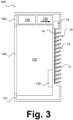
Figure 3 illustrates the galley insert according toFigure 2 in a second state of operation. -
Figure 4 illustrates the galley insert according toFigure 2 in a third state of operation. -
Figure 5 illustrates a galley insert in a longitudinal sectional view in a first state of operation. -
Figure 6 illustrates the galley insert according toFigure 5 in a second state of operation. -
Figure 7 illustrates a galley insert in a longitudinal sectional view in a state of operation. -
Figures 8A and 8B schematically illustrate an adjustment drive. -
Figures 9A and 9B schematically illustrate an adjustment drive. - In the Figures, elements of identical, essentially identical, functionally comparable, or technically compatible function and/or purpose may be identified with identical reference numerals, and repeated explanations may be omitted for reasons of conciseness. Explanations herein relating to devices, apparatus, arrangements, systems, etc., according to embodiments likewise may apply to methods, processes, procedures, etc. according to embodiments and vice versa.
- The various embodiments described herein are presented only to assist in understanding and teaching the claimed features. These embodiments are provided as a representative sample of embodiments only and are not exhaustive and/or exclusive. It is to be understood that advantages, embodiments, examples, functions, features, structures, and/or other aspects described herein are not to be considered limitations on the scope of the invention as defined by the claims or limitations on equivalents to the claims, and that other embodiments may be utilised, and modifications may be made without departing from the scope of the claimed invention. Various embodiments of the invention may suitably comprise, consist of, or consist essentially of, appropriate combinations of the disclosed elements, components, features, parts, steps, means, etc., other than those specifically described herein. In addition, this disclosure may include other inventions not presently claimed, but which may be claimed in future, particularly when encompassed by the scope of the independent claims.
-
Figure 1 schematically illustrates a galley insert of the type described above and an isometric view. The insert as shown inFigure 1 is designated 1000. Galley insert 1000 represents, for example, an oven insert such as may be used in the galley of an aircraft for heating food and/or beverages. Galley insert 1000 comprises awall 110, which, in the example illustrated, is formed by a plurality of wall panels.Wall 110 provides a certain thermal insulation of galley insert 1000 towards the outside. - In the external view according to
Figure 1 , adoor unit 140 is visible, which allows access to an oven chamber that is not visible inFigure 1 . Furthermore, afront panel 160 is visible, which can be used, for example, for inputting and/or outputting information to a control unit of galley insert 1000, which is also not visible inFigure 1 , and which may include an air inlet grid whose function will be evident from the explanations below. Galley insert 1000 may comprise carrying structures which are not indicated with reference numerals. - In order to allow heat to be dissipated from the galley insert 1000, an
exhaust arrangement 190 is provided, which in the example shown has rigidly designed deflecting lamellas. As mentioned at the outset, the rigidity of such lamellas in conventional arrangements can result in hot exhaust air from the galley insert 1000 acting more strongly on localized regions of the surroundings, particularly of a galley structure into which the galley insert is inserted, so that heat accumulation or hot spots can occur. - Therefore, embodiments of the present disclosure, which are illustrated in connection with the subsequent Figures, provide for a flexible and particularly temperature dependent deflection of exhaust air, which particularly is realized by a bimetallic actor or other temperature-dependent actor, such that hot spots and local temperature accumulation, particularly in a galley structure, can be avoided.
-
Figure 2 illustrates a galley insert which is configured accordingly in a longitudinal section. The galley insert shown inFigure 2 is indicated withreference numeral 100 and may, except for the differences discussed below, essentially or in parts correspond in size, technical realization and function, to galley insert 1000 shown inFigure 1 . - In the longitudinal sectional view of
Figure 2 , anoven chamber 120 is schematically illustrated. On top of theoven chamber 120, anexhaust fan arrangement 130 may be provided which may generate an air stream as indicated with a bold arrow. This air stream may dissipate heat away fromoven chamber 120 or the proximity thereof towards, conventionally, anexhaust arrangement 190 as shown inFigure 1 , particularly at the sides ofgalley insert 110. Acontrol unit 150 is also illustrated inFigure 2 . - Galley insert 100 according to
Figure 2 comprises anexhaust arrangement 10 in which a plurality of pivotable deflection lamellas 11 is provided. Be it noted that, while theexhaust arrangement 10 is illustrated inFigure 2 at the back wall of the Galley insert 100 for reasons of simplification, a typical location would correspond to a location of theexhaust arrangement 190 as shown inFigure 1 , but embodiments disclosed herein are not limited in terms of a specific location. Several exhaust arrangements, in larger or smaller dimensions than depicted, or in different dimensions, different air cross sections, different orientations etc. may be present in embodiments. - Deflection lamellas 11 of the exhaust arrangement are, in the example illustrated, rotatably or pivotably mounted at a
rotational axis 13, which is oriented vertically to the paper plane in the example illustrated, to a mountingstructure 12 or may be otherwise be made to be rotatable. Anadjustment rod 14 is provided which may be longitudinally positioned using anadjustment drive 15, such as further explained below. Here, and below, elements provided in plurality may be designated with a reference numeral only once and the same, or different, explanations may apply to all of these elements. -
Adjustment drive 15, which may comprise a bimetallic actor, is adapted to perform an adjustment of deflection lamellas 11 by longitudinally displacingadjustment rod 14, which in turn engages withdeflection lamellas 11 via suitable engagement structures such as oblong holes and changes their angular positions. Such an adjustment is particularly illustrated with reference toFigures 3 und4 which illustrategalley insert 100, which is shown inFigure 2 in a first operation state, in a second and third operation state resulting from such an adjustment. - Be it noted that the orientation of deflection lamellas 11 and the
overall exhaust arrangement 10 may be arbitrarily selected, based on needs of heat dissipation, special confinement, general practicability, optical reasons, mechanical load, etc. Even if distinct operation states are illustrated inFigures 2 ,3 and4 , certain embodiments include a continuous adjustment correlating to the temperature rather than a stepwise adjustment. This allows for a particularly advantageous distribution of heat. - In all cases, adjustment drive 15 may particularly be arranged in an air stream of the air flow generated by the
exhaust fan arrangement 130, and indeed may be placed, in embodiments, at any position suitable, particularly at a position at which a representative, maximum, minimum, or average temperature may generally be present. -
Figure 5 illustrates a further embodiment of a galley insert which is referred to withreference numeral 200. Galley insert 200 may, except for the differences discussed below, essentially or at least in parts correspond in size, technical realization and function of its parts, togalley inserts 1000 and 100 shown inFigures 1 to 4 . - As illustrated in
Figure 5 , an exhaust arrangement, which is indicated 20 inFigure 5 , may comprise two groups ofdeflection lamellas adjustment rods adjustment drives adjustment drive - Such an adjustment is particularly illustrated with reference to
Figure 6 , in which illustrategalley insert 200, which is shown inFigure 5 in a first operation state, is shown in a second operation state resulting from such an adjustment. An adjustment as illustrated here may particularly serve to deflect exhaust air to different points or locations in the surroundings and may a particularly advantageous adaptation to varying temperature conditions. Again, even if distinct operation states are shown inFigures 5 and6 , these may in embodiments rather be snapshots of a continuous adjustment according to the principles already discussed. -
Figure 7 illustrates a further embodiment of a galley insert which is referred to withreference numeral 300. Galley insert 300 may, except for the differences discussed below, essentially or at least in parts correspond in size, technical realization and function, togalley inserts Figures 1 to 6 . - As illustrated in
Figure 7 , deflection lamellas 11 in anexhaust arrangement 30 may be actuated, individually or in groups, in anexhaust arrangement 30, by individual adjustment drives 16 which may be located in proximity of therotational axes 13 to directly adjust the associateddeflection lamella 11. An adjusted lamella may be coupled to further deflection lamellas 11, to provide an unison adjustment, or they may be uncoupled, in order to even better distribute exhaust air. -
Figures 8A and 8B illustrate adjustment drives 15 which could be used in embodiments as shown before, particularly in galley inserts 100 and 200. - In the adjustment drives 15, a
bimetallic coil 17, or a set of bimetallic coils, such as to increase an adjustment force, is installed.Bimetallic coil 17 or the coils of a corresponding arrangement may be centrally fixed to a structure, and the opposite end may be connected to anadjustment rod 14 as shown before. By virtue of an expansion ofcoil 17,adjustment rod 14 may be deployed, as shown inFigure 8B vs.Figure 8A , from a retracted state to a deployed state. For mechanical guidance of adjustingrod 14, a guidingarrangement 18 such as a linear guide or a hollow shaft may also be provided. - Other means of interconnection between the
bimetallic coil 17 and theadjustment rod 14 may be provided, such as rack-and-pinion drives where the centre of the bimetallic coil may be mechanically coupled to a pinion and the opposite end may be fixed and the pinion may engage with a rack or rack portion at theadjustment rod 14. This may result in a better utilization of the relatively low forces present. - and
Figures 9A and 9B illustrate adjustment drives 16 of a type utilizable e.g. in the embodiment shown inFigure 7 , i.e.galley insert 300. Herein, abimetallic coil 17, or a set of bimetallic coils may be coupled directly to adeflection lamella 11 or itsaxis 13 to allow for a direct transmission of the adjustment force.
Claims (10)
- A galley insert (100, 200, 300) for an aircraft galley, the galley insert (100, 200, 300) comprising heating equipment (120) and an exhaust arrangement (10, 20, 30) configured to pass an exhaust air stream out of the galley insert (100, 200, 300), wherein the exhaust arrangement (10, 20, 30) comprises a plurality of deflection lamellas (11, 11a, 11b) configured to adjust a direction of the exhaust air stream, characterized in that at least some of the deflection lamellas (11, 11a, 11b) are configured to be angularly adjusted on the basis of a temperature of the exhaust air stream using one or more temperature-dependent actors.
- The galley insert (100, 200, 300) according to claim 1, wherein the, or at least one of the, temperature dependent actors is or includes one or more bimetallic coils (17).
- The galley insert (100, 200, 300) according to claim 1 or 2, wherein one or more adjustment rods (14, 14a, 14b) are provided which is or are configured to engage with one or more groups of the deflection lamellas (11, 11a, 11b).
- The galley insert (100, 200, 300) according to claim 3, wherein the, or at least one of the, adjustment rods is configured to engage with the, or at least one of the, temperature-dependent actors via one or more mechanical couplings.
- The galley insert (100, 200, 300) according to claim 4, wherein the, or at least one of the, mechanical couplings is provided as a rotatable connection, a rigid connection, or a geared coupling such as a rack-and-pinion arrangement.
- The galley insert (100, 200, 300) according to any one of the preceding claims wherein at least one of the deflection lamellas (11, 11a, 11b) is individually coupled with the, or at least one of the, temperature-dependent actors.
- The galley insert (100, 200, 300) according to any one of the preceding claims, wherein the, or at least of the, temperature-dependent actors are configured to provide a continuous adjustment depending on the temperature.
- The galley insert (100, 200, 300) according to any one of the preceding claims, wherein the exhaust stream is generated using an exhaust fan arrangement (130) arranged within a housing (110) of the galley insert.
- The galley insert (100, 200, 300) according to any one of the preceding claims being configured to be operated as an oven selected from a convection oven, a microwave oven, and a steam oven, a bun warmer, a plate warmer, a coffee maker, a beverage maker, a water boiler, a water heater, a rice cooker, a coffee warmer and a hot jug.
- A method of heating a food or beverage or food or beverage carrier in a galley of an aircraft, characterized in that a galley insert (100, 200, 300) according to any one of the preceding claims is used.
Priority Applications (2)
| Application Number | Priority Date | Filing Date | Title |
|---|---|---|---|
| EP22208165.5A EP4371879B1 (en) | 2022-11-17 | 2022-11-17 | Aircraft galley insert |
| US18/499,552 US20240166353A1 (en) | 2022-11-17 | 2023-11-01 | Aircraft galley insert |
Applications Claiming Priority (1)
| Application Number | Priority Date | Filing Date | Title |
|---|---|---|---|
| EP22208165.5A EP4371879B1 (en) | 2022-11-17 | 2022-11-17 | Aircraft galley insert |
Publications (2)
| Publication Number | Publication Date |
|---|---|
| EP4371879A1 true EP4371879A1 (en) | 2024-05-22 |
| EP4371879B1 EP4371879B1 (en) | 2026-05-06 |
Family
ID=84359466
Family Applications (1)
| Application Number | Title | Priority Date | Filing Date |
|---|---|---|---|
| EP22208165.5A Active EP4371879B1 (en) | 2022-11-17 | 2022-11-17 | Aircraft galley insert |
Country Status (2)
| Country | Link |
|---|---|
| US (1) | US20240166353A1 (en) |
| EP (1) | EP4371879B1 (en) |
Citations (4)
| Publication number | Priority date | Publication date | Assignee | Title |
|---|---|---|---|---|
| EP2874880B1 (en) * | 2012-07-20 | 2016-08-24 | Sell Gmbh | Cooling concept back panel |
| GB2571986A (en) * | 2018-03-15 | 2019-09-18 | Ipeco Holdings Ltd | Galley apparatus |
| US20210221513A1 (en) * | 2020-01-17 | 2021-07-22 | Koninklijke Fabriek Inventum B.V. | Titanium Inner Shell for Electrical Galley Inserts |
| US20210291986A1 (en) * | 2019-06-25 | 2021-09-23 | Koninklijke Fabriek Inventum B. V. | Optimized Electronics Grounding Path for High-Frequency Noise |
Family Cites Families (11)
| Publication number | Priority date | Publication date | Assignee | Title |
|---|---|---|---|---|
| US1619621A (en) * | 1927-03-01 | Radiator-shutter | ||
| US4231514A (en) * | 1979-09-10 | 1980-11-04 | Mcswain Edward D | Automatic ventilator |
| JPS6096533U (en) * | 1983-12-07 | 1985-07-01 | 加藤発条株式会社 | Louver angle automatic adjustment device |
| US4715532A (en) * | 1986-07-16 | 1987-12-29 | Paul M. Sarazen | Adjustably resettable, temperature-responsive automatic ventilator |
| US5253804A (en) * | 1992-05-12 | 1993-10-19 | Sarazen Jr Paul M | Temperature and humidity sensitive high efficiency exhaust ventilator apparatus |
| US5294049A (en) * | 1993-02-22 | 1994-03-15 | Temp-Vent Corporation | Power temp vent duct system |
| US5984196A (en) * | 1997-09-18 | 1999-11-16 | Godsey; Edward L. | Thermal rotary vent |
| US8922033B2 (en) * | 2013-03-04 | 2014-12-30 | General Electric Company | System for cooling power generation system |
| US10407173B2 (en) * | 2014-03-10 | 2019-09-10 | The Boeing Company | Dry ice draw through galley cooling |
| US11333364B2 (en) * | 2018-04-05 | 2022-05-17 | Rockwell Collins, Inc. | Adaptive cooking system |
| US11958615B2 (en) * | 2020-03-27 | 2024-04-16 | B/E Aerospace, Inc. | Thermostatically controlled galley air extraction |
-
2022
- 2022-11-17 EP EP22208165.5A patent/EP4371879B1/en active Active
-
2023
- 2023-11-01 US US18/499,552 patent/US20240166353A1/en active Pending
Patent Citations (4)
| Publication number | Priority date | Publication date | Assignee | Title |
|---|---|---|---|---|
| EP2874880B1 (en) * | 2012-07-20 | 2016-08-24 | Sell Gmbh | Cooling concept back panel |
| GB2571986A (en) * | 2018-03-15 | 2019-09-18 | Ipeco Holdings Ltd | Galley apparatus |
| US20210291986A1 (en) * | 2019-06-25 | 2021-09-23 | Koninklijke Fabriek Inventum B. V. | Optimized Electronics Grounding Path for High-Frequency Noise |
| US20210221513A1 (en) * | 2020-01-17 | 2021-07-22 | Koninklijke Fabriek Inventum B.V. | Titanium Inner Shell for Electrical Galley Inserts |
Also Published As
| Publication number | Publication date |
|---|---|
| US20240166353A1 (en) | 2024-05-23 |
| EP4371879B1 (en) | 2026-05-06 |
Similar Documents
| Publication | Publication Date | Title |
|---|---|---|
| US9581145B2 (en) | Shape memory alloy actuation system for variable area fan nozzle | |
| US9803873B2 (en) | Oven range appliance | |
| CN103155960A (en) | Combination oven with catalytic converter | |
| CN102414516B (en) | cooking equipment | |
| US8017889B2 (en) | Radiant convection baffle for ovens | |
| EP2592355A1 (en) | Cooking hob, household appliance and method of operating an cooking hob | |
| US20130259455A1 (en) | Vehicle Oven Having an Optimized Water Vapor Injector | |
| US20240166353A1 (en) | Aircraft galley insert | |
| EP2830423B1 (en) | Oven and method of heating an oven | |
| US12144088B2 (en) | Induction cooktop | |
| KR101791183B1 (en) | Induction range | |
| EP2928276A1 (en) | Cooling flow optimization | |
| EP1739013B1 (en) | A device and an aircraft anti-icing system comprising such a device | |
| CN113135292A (en) | Titanium inner shell of electric kitchen insert | |
| EP2966288B1 (en) | Ventilation inlet | |
| US20190316777A1 (en) | Fireplace system, heat exchanger and method | |
| US20130312731A1 (en) | Fan apparency arrangement for an appliance | |
| EP0830063A1 (en) | A heater unit for ovens | |
| EP2241820B1 (en) | Oven with external cooling and method of operating | |
| US8671941B2 (en) | Respirator | |
| KR102419401B1 (en) | Multi-tube type Furnace Device | |
| JP2010007984A (en) | Heating cooker | |
| EP3757476B1 (en) | Heating apparatus | |
| EP3666655B1 (en) | Aircraft propulsion system including a heat exchanger system | |
| CZ29634U1 (en) | Rack oven and baking oven system |
Legal Events
| Date | Code | Title | Description |
|---|---|---|---|
| PUAI | Public reference made under article 153(3) epc to a published international application that has entered the european phase |
Free format text: ORIGINAL CODE: 0009012 |
|
| STAA | Information on the status of an ep patent application or granted ep patent |
Free format text: STATUS: THE APPLICATION HAS BEEN PUBLISHED |
|
| AK | Designated contracting states |
Kind code of ref document: A1 Designated state(s): AL AT BE BG CH CY CZ DE DK EE ES FI FR GB GR HR HU IE IS IT LI LT LU LV MC ME MK MT NL NO PL PT RO RS SE SI SK SM TR |
|
| STAA | Information on the status of an ep patent application or granted ep patent |
Free format text: STATUS: REQUEST FOR EXAMINATION WAS MADE |
|
| 17P | Request for examination filed |
Effective date: 20241122 |
|
| RBV | Designated contracting states (corrected) |
Designated state(s): AL AT BE BG CH CY CZ DE DK EE ES FI FR GB GR HR HU IE IS IT LI LT LU LV MC ME MK MT NL NO PL PT RO RS SE SI SK SM TR |
|
| GRAJ | Information related to disapproval of communication of intention to grant by the applicant or resumption of examination proceedings by the epo deleted |
Free format text: ORIGINAL CODE: EPIDOSDIGR1 |
|
| GRAP | Despatch of communication of intention to grant a patent |
Free format text: ORIGINAL CODE: EPIDOSNIGR1 |
|
| RIC1 | Information provided on ipc code assigned before grant |
Ipc: B64D 11/04 20060101AFI20251107BHEP |
|
| GRAP | Despatch of communication of intention to grant a patent |
Free format text: ORIGINAL CODE: EPIDOSNIGR1 |
|
| STAA | Information on the status of an ep patent application or granted ep patent |
Free format text: STATUS: GRANT OF PATENT IS INTENDED |
|
| INTG | Intention to grant announced |
Effective date: 20260107 |
|
| GRAS | Grant fee paid |
Free format text: ORIGINAL CODE: EPIDOSNIGR3 |
|
| GRAA | (expected) grant |
Free format text: ORIGINAL CODE: 0009210 |
|
| STAA | Information on the status of an ep patent application or granted ep patent |
Free format text: STATUS: THE PATENT HAS BEEN GRANTED |
|
| AK | Designated contracting states |
Kind code of ref document: B1 Designated state(s): AL AT BE BG CH CY CZ DE DK EE ES FI FR GB GR HR HU IE IS IT LI LT LU LV MC ME MK MT NL NO PL PT RO RS SE SI SK SM TR |
|
| REG | Reference to a national code |
Ref country code: CH Ref legal event code: F10 Free format text: ST27 STATUS EVENT CODE: U-0-0-F10-F00 (AS PROVIDED BY THE NATIONAL OFFICE) Effective date: 20260506 Ref country code: GB Ref legal event code: FG4D |