EP3666655B1 - Aircraft propulsion system including a heat exchanger system - Google Patents
Aircraft propulsion system including a heat exchanger system Download PDFInfo
- Publication number
- EP3666655B1 EP3666655B1 EP18306695.0A EP18306695A EP3666655B1 EP 3666655 B1 EP3666655 B1 EP 3666655B1 EP 18306695 A EP18306695 A EP 18306695A EP 3666655 B1 EP3666655 B1 EP 3666655B1
- Authority
- EP
- European Patent Office
- Prior art keywords
- heat exchanger
- stage
- channels
- connection
- cold
- Prior art date
- Legal status (The legal status is an assumption and is not a legal conclusion. Google has not performed a legal analysis and makes no representation as to the accuracy of the status listed.)
- Active
Links
- 230000006835 compression Effects 0.000 claims description 6
- 238000007906 compression Methods 0.000 claims description 6
- 230000001105 regulatory effect Effects 0.000 description 3
- 238000004378 air conditioning Methods 0.000 description 2
- 230000010354 integration Effects 0.000 description 2
- 230000001143 conditioned effect Effects 0.000 description 1
- 230000000694 effects Effects 0.000 description 1
- 239000000463 material Substances 0.000 description 1
- 239000002184 metal Substances 0.000 description 1
Images

Classifications
-
- B—PERFORMING OPERATIONS; TRANSPORTING
- B64—AIRCRAFT; AVIATION; COSMONAUTICS
- B64D—EQUIPMENT FOR FITTING IN OR TO AIRCRAFT; FLIGHT SUITS; PARACHUTES; ARRANGEMENTS OR MOUNTING OF POWER PLANTS OR PROPULSION TRANSMISSIONS IN AIRCRAFT
- B64D27/00—Arrangement or mounting of power plant in aircraft; Aircraft characterised thereby
- B64D27/02—Aircraft characterised by the type or position of power plant
- B64D27/04—Aircraft characterised by the type or position of power plant of piston type
- B64D27/06—Aircraft characterised by the type or position of power plant of piston type within or attached to wing
-
- F—MECHANICAL ENGINEERING; LIGHTING; HEATING; WEAPONS; BLASTING
- F02—COMBUSTION ENGINES; HOT-GAS OR COMBUSTION-PRODUCT ENGINE PLANTS
- F02C—GAS-TURBINE PLANTS; AIR INTAKES FOR JET-PROPULSION PLANTS; CONTROLLING FUEL SUPPLY IN AIR-BREATHING JET-PROPULSION PLANTS
- F02C7/00—Features, components parts, details or accessories, not provided for in, or of interest apart form groups F02C1/00 - F02C6/00; Air intakes for jet-propulsion plants
- F02C7/08—Heating air supply before combustion, e.g. by exhaust gases
- F02C7/10—Heating air supply before combustion, e.g. by exhaust gases by means of regenerative heat-exchangers
-
- B—PERFORMING OPERATIONS; TRANSPORTING
- B64—AIRCRAFT; AVIATION; COSMONAUTICS
- B64D—EQUIPMENT FOR FITTING IN OR TO AIRCRAFT; FLIGHT SUITS; PARACHUTES; ARRANGEMENTS OR MOUNTING OF POWER PLANTS OR PROPULSION TRANSMISSIONS IN AIRCRAFT
- B64D33/00—Arrangements in aircraft of power plant parts or auxiliaries not otherwise provided for
- B64D33/02—Arrangements in aircraft of power plant parts or auxiliaries not otherwise provided for of combustion air intakes
-
- B—PERFORMING OPERATIONS; TRANSPORTING
- B64—AIRCRAFT; AVIATION; COSMONAUTICS
- B64D—EQUIPMENT FOR FITTING IN OR TO AIRCRAFT; FLIGHT SUITS; PARACHUTES; ARRANGEMENTS OR MOUNTING OF POWER PLANTS OR PROPULSION TRANSMISSIONS IN AIRCRAFT
- B64D13/00—Arrangements or adaptations of air-treatment apparatus for aircraft crew or passengers, or freight space, or structural parts of the aircraft
- B64D13/06—Arrangements or adaptations of air-treatment apparatus for aircraft crew or passengers, or freight space, or structural parts of the aircraft the air being conditioned
- B64D13/08—Arrangements or adaptations of air-treatment apparatus for aircraft crew or passengers, or freight space, or structural parts of the aircraft the air being conditioned the air being heated or cooled
-
- B—PERFORMING OPERATIONS; TRANSPORTING
- B64—AIRCRAFT; AVIATION; COSMONAUTICS
- B64D—EQUIPMENT FOR FITTING IN OR TO AIRCRAFT; FLIGHT SUITS; PARACHUTES; ARRANGEMENTS OR MOUNTING OF POWER PLANTS OR PROPULSION TRANSMISSIONS IN AIRCRAFT
- B64D15/00—De-icing or preventing icing on exterior surfaces of aircraft
- B64D15/02—De-icing or preventing icing on exterior surfaces of aircraft by ducted hot gas or liquid
- B64D15/04—Hot gas application
-
- B—PERFORMING OPERATIONS; TRANSPORTING
- B64—AIRCRAFT; AVIATION; COSMONAUTICS
- B64D—EQUIPMENT FOR FITTING IN OR TO AIRCRAFT; FLIGHT SUITS; PARACHUTES; ARRANGEMENTS OR MOUNTING OF POWER PLANTS OR PROPULSION TRANSMISSIONS IN AIRCRAFT
- B64D27/00—Arrangement or mounting of power plant in aircraft; Aircraft characterised thereby
- B64D27/02—Aircraft characterised by the type or position of power plant
- B64D27/16—Aircraft characterised by the type or position of power plant of jet type
- B64D27/18—Aircraft characterised by the type or position of power plant of jet type within or attached to wing
-
- B64D27/40—
-
- B64D27/402—
-
- B—PERFORMING OPERATIONS; TRANSPORTING
- B64—AIRCRAFT; AVIATION; COSMONAUTICS
- B64D—EQUIPMENT FOR FITTING IN OR TO AIRCRAFT; FLIGHT SUITS; PARACHUTES; ARRANGEMENTS OR MOUNTING OF POWER PLANTS OR PROPULSION TRANSMISSIONS IN AIRCRAFT
- B64D29/00—Power-plant nacelles, fairings, or cowlings
- B64D29/02—Power-plant nacelles, fairings, or cowlings associated with wings
-
- B—PERFORMING OPERATIONS; TRANSPORTING
- B64—AIRCRAFT; AVIATION; COSMONAUTICS
- B64D—EQUIPMENT FOR FITTING IN OR TO AIRCRAFT; FLIGHT SUITS; PARACHUTES; ARRANGEMENTS OR MOUNTING OF POWER PLANTS OR PROPULSION TRANSMISSIONS IN AIRCRAFT
- B64D33/00—Arrangements in aircraft of power plant parts or auxiliaries not otherwise provided for
- B64D33/04—Arrangements in aircraft of power plant parts or auxiliaries not otherwise provided for of exhaust outlets or jet pipes
-
- F—MECHANICAL ENGINEERING; LIGHTING; HEATING; WEAPONS; BLASTING
- F02—COMBUSTION ENGINES; HOT-GAS OR COMBUSTION-PRODUCT ENGINE PLANTS
- F02C—GAS-TURBINE PLANTS; AIR INTAKES FOR JET-PROPULSION PLANTS; CONTROLLING FUEL SUPPLY IN AIR-BREATHING JET-PROPULSION PLANTS
- F02C6/00—Plural gas-turbine plants; Combinations of gas-turbine plants with other apparatus; Adaptations of gas- turbine plants for special use
- F02C6/04—Gas-turbine plants providing heated or pressurised working fluid for other apparatus, e.g. without mechanical power output
- F02C6/06—Gas-turbine plants providing heated or pressurised working fluid for other apparatus, e.g. without mechanical power output providing compressed gas
- F02C6/08—Gas-turbine plants providing heated or pressurised working fluid for other apparatus, e.g. without mechanical power output providing compressed gas the gas being bled from the gas-turbine compressor
-
- F—MECHANICAL ENGINEERING; LIGHTING; HEATING; WEAPONS; BLASTING
- F02—COMBUSTION ENGINES; HOT-GAS OR COMBUSTION-PRODUCT ENGINE PLANTS
- F02C—GAS-TURBINE PLANTS; AIR INTAKES FOR JET-PROPULSION PLANTS; CONTROLLING FUEL SUPPLY IN AIR-BREATHING JET-PROPULSION PLANTS
- F02C7/00—Features, components parts, details or accessories, not provided for in, or of interest apart form groups F02C1/00 - F02C6/00; Air intakes for jet-propulsion plants
- F02C7/04—Air intakes for gas-turbine plants or jet-propulsion plants
- F02C7/047—Heating to prevent icing
-
- F—MECHANICAL ENGINEERING; LIGHTING; HEATING; WEAPONS; BLASTING
- F02—COMBUSTION ENGINES; HOT-GAS OR COMBUSTION-PRODUCT ENGINE PLANTS
- F02C—GAS-TURBINE PLANTS; AIR INTAKES FOR JET-PROPULSION PLANTS; CONTROLLING FUEL SUPPLY IN AIR-BREATHING JET-PROPULSION PLANTS
- F02C7/00—Features, components parts, details or accessories, not provided for in, or of interest apart form groups F02C1/00 - F02C6/00; Air intakes for jet-propulsion plants
- F02C7/12—Cooling of plants
- F02C7/14—Cooling of plants of fluids in the plant, e.g. lubricant or fuel
-
- F—MECHANICAL ENGINEERING; LIGHTING; HEATING; WEAPONS; BLASTING
- F02—COMBUSTION ENGINES; HOT-GAS OR COMBUSTION-PRODUCT ENGINE PLANTS
- F02C—GAS-TURBINE PLANTS; AIR INTAKES FOR JET-PROPULSION PLANTS; CONTROLLING FUEL SUPPLY IN AIR-BREATHING JET-PROPULSION PLANTS
- F02C7/00—Features, components parts, details or accessories, not provided for in, or of interest apart form groups F02C1/00 - F02C6/00; Air intakes for jet-propulsion plants
- F02C7/12—Cooling of plants
- F02C7/16—Cooling of plants characterised by cooling medium
- F02C7/18—Cooling of plants characterised by cooling medium the medium being gaseous, e.g. air
- F02C7/185—Cooling means for reducing the temperature of the cooling air or gas
-
- F—MECHANICAL ENGINEERING; LIGHTING; HEATING; WEAPONS; BLASTING
- F28—HEAT EXCHANGE IN GENERAL
- F28D—HEAT-EXCHANGE APPARATUS, NOT PROVIDED FOR IN ANOTHER SUBCLASS, IN WHICH THE HEAT-EXCHANGE MEDIA DO NOT COME INTO DIRECT CONTACT
- F28D21/00—Heat-exchange apparatus not covered by any of the groups F28D1/00 - F28D20/00
- F28D21/0001—Recuperative heat exchangers
- F28D21/0003—Recuperative heat exchangers the heat being recuperated from exhaust gases
-
- F—MECHANICAL ENGINEERING; LIGHTING; HEATING; WEAPONS; BLASTING
- F28—HEAT EXCHANGE IN GENERAL
- F28D—HEAT-EXCHANGE APPARATUS, NOT PROVIDED FOR IN ANOTHER SUBCLASS, IN WHICH THE HEAT-EXCHANGE MEDIA DO NOT COME INTO DIRECT CONTACT
- F28D21/00—Heat-exchange apparatus not covered by any of the groups F28D1/00 - F28D20/00
- F28D21/0001—Recuperative heat exchangers
- F28D21/0014—Recuperative heat exchangers the heat being recuperated from waste air or from vapors
-
- B—PERFORMING OPERATIONS; TRANSPORTING
- B64—AIRCRAFT; AVIATION; COSMONAUTICS
- B64D—EQUIPMENT FOR FITTING IN OR TO AIRCRAFT; FLIGHT SUITS; PARACHUTES; ARRANGEMENTS OR MOUNTING OF POWER PLANTS OR PROPULSION TRANSMISSIONS IN AIRCRAFT
- B64D13/00—Arrangements or adaptations of air-treatment apparatus for aircraft crew or passengers, or freight space, or structural parts of the aircraft
- B64D13/06—Arrangements or adaptations of air-treatment apparatus for aircraft crew or passengers, or freight space, or structural parts of the aircraft the air being conditioned
- B64D2013/0603—Environmental Control Systems
- B64D2013/0607—Environmental Control Systems providing hot air or liquid for deicing aircraft parts, e.g. aerodynamic surfaces or windows
-
- B—PERFORMING OPERATIONS; TRANSPORTING
- B64—AIRCRAFT; AVIATION; COSMONAUTICS
- B64D—EQUIPMENT FOR FITTING IN OR TO AIRCRAFT; FLIGHT SUITS; PARACHUTES; ARRANGEMENTS OR MOUNTING OF POWER PLANTS OR PROPULSION TRANSMISSIONS IN AIRCRAFT
- B64D13/00—Arrangements or adaptations of air-treatment apparatus for aircraft crew or passengers, or freight space, or structural parts of the aircraft
- B64D13/06—Arrangements or adaptations of air-treatment apparatus for aircraft crew or passengers, or freight space, or structural parts of the aircraft the air being conditioned
- B64D2013/0603—Environmental Control Systems
- B64D2013/0618—Environmental Control Systems with arrangements for reducing or managing bleed air, using another air source, e.g. ram air
-
- B—PERFORMING OPERATIONS; TRANSPORTING
- B64—AIRCRAFT; AVIATION; COSMONAUTICS
- B64D—EQUIPMENT FOR FITTING IN OR TO AIRCRAFT; FLIGHT SUITS; PARACHUTES; ARRANGEMENTS OR MOUNTING OF POWER PLANTS OR PROPULSION TRANSMISSIONS IN AIRCRAFT
- B64D33/00—Arrangements in aircraft of power plant parts or auxiliaries not otherwise provided for
- B64D33/02—Arrangements in aircraft of power plant parts or auxiliaries not otherwise provided for of combustion air intakes
- B64D2033/024—Arrangements in aircraft of power plant parts or auxiliaries not otherwise provided for of combustion air intakes comprising cooling means
-
- F—MECHANICAL ENGINEERING; LIGHTING; HEATING; WEAPONS; BLASTING
- F05—INDEXING SCHEMES RELATING TO ENGINES OR PUMPS IN VARIOUS SUBCLASSES OF CLASSES F01-F04
- F05D—INDEXING SCHEME FOR ASPECTS RELATING TO NON-POSITIVE-DISPLACEMENT MACHINES OR ENGINES, GAS-TURBINES OR JET-PROPULSION PLANTS
- F05D2220/00—Application
- F05D2220/30—Application in turbines
- F05D2220/32—Application in turbines in gas turbines
- F05D2220/323—Application in turbines in gas turbines for aircraft propulsion, e.g. jet engines
-
- F—MECHANICAL ENGINEERING; LIGHTING; HEATING; WEAPONS; BLASTING
- F05—INDEXING SCHEMES RELATING TO ENGINES OR PUMPS IN VARIOUS SUBCLASSES OF CLASSES F01-F04
- F05D—INDEXING SCHEME FOR ASPECTS RELATING TO NON-POSITIVE-DISPLACEMENT MACHINES OR ENGINES, GAS-TURBINES OR JET-PROPULSION PLANTS
- F05D2260/00—Function
- F05D2260/20—Heat transfer, e.g. cooling
- F05D2260/213—Heat transfer, e.g. cooling by the provision of a heat exchanger within the cooling circuit
-
- F—MECHANICAL ENGINEERING; LIGHTING; HEATING; WEAPONS; BLASTING
- F28—HEAT EXCHANGE IN GENERAL
- F28D—HEAT-EXCHANGE APPARATUS, NOT PROVIDED FOR IN ANOTHER SUBCLASS, IN WHICH THE HEAT-EXCHANGE MEDIA DO NOT COME INTO DIRECT CONTACT
- F28D21/00—Heat-exchange apparatus not covered by any of the groups F28D1/00 - F28D20/00
- F28D2021/0019—Other heat exchangers for particular applications; Heat exchange systems not otherwise provided for
- F28D2021/0021—Other heat exchangers for particular applications; Heat exchange systems not otherwise provided for for aircrafts or cosmonautics
-
- Y—GENERAL TAGGING OF NEW TECHNOLOGICAL DEVELOPMENTS; GENERAL TAGGING OF CROSS-SECTIONAL TECHNOLOGIES SPANNING OVER SEVERAL SECTIONS OF THE IPC; TECHNICAL SUBJECTS COVERED BY FORMER USPC CROSS-REFERENCE ART COLLECTIONS [XRACs] AND DIGESTS
- Y02—TECHNOLOGIES OR APPLICATIONS FOR MITIGATION OR ADAPTATION AGAINST CLIMATE CHANGE
- Y02T—CLIMATE CHANGE MITIGATION TECHNOLOGIES RELATED TO TRANSPORTATION
- Y02T50/00—Aeronautics or air transport
- Y02T50/50—On board measures aiming to increase energy efficiency
-
- Y—GENERAL TAGGING OF NEW TECHNOLOGICAL DEVELOPMENTS; GENERAL TAGGING OF CROSS-SECTIONAL TECHNOLOGIES SPANNING OVER SEVERAL SECTIONS OF THE IPC; TECHNICAL SUBJECTS COVERED BY FORMER USPC CROSS-REFERENCE ART COLLECTIONS [XRACs] AND DIGESTS
- Y02—TECHNOLOGIES OR APPLICATIONS FOR MITIGATION OR ADAPTATION AGAINST CLIMATE CHANGE
- Y02T—CLIMATE CHANGE MITIGATION TECHNOLOGIES RELATED TO TRANSPORTATION
- Y02T50/00—Aeronautics or air transport
- Y02T50/60—Efficient propulsion technologies, e.g. for aircraft
Definitions
- An aim of the present invention is to propose an aircraft propulsion system including a heat exchanger system, which is less bulky and thus enables better integration in the propulsion system.
- the heat exchanger includes a first stage and a second stage disposed aft of the first stage, first cold channels and first hot channels are placed in the first stage, second cold channels and second hot channels are placed in the second stage, the first cold channels and the second cold channels are connected together, the first hot channels and the second hot channels are connected together, forward of the first stage, the first hot channels are connected to the supply connection, forward of the first stage, the first cold channels are connected to the evacuation connection, the second stage has the shape of a truncated pyramid, which has a large base and a small base perpendicular to the first transfer direction and which has two sides inclined between the large base and the small base, the large base constitutes the junction zone between the first stage and the second stage, the small base constitutes the zone where only the second hot channels emerge and where the junction is made with the transfer connection, and each side constitutes the zone where only the second cold channels emerge and where the junction is made with one of the two scoop connections.
- the passage of the hot air through the heat exchanger 202 from the supply pipe 204 to the transfer pipe 222 takes place along a first transfer direction 60, which here is globally parallel to the longitudinal axis X and is here oriented from forward to aft.
- the first stage 302 is a box in which first cold channels 304 and first hot channels 306 are placed.
- the second stage 402 is a box in which second cold channels 404 and second hot channels 406 are placed.
- the first stage 302 and the second stage 402 are made of materials having a high heat transfer coefficient, such as metal for example.
- the cold channels 304, 404 and the hot channels 306, 406 are preferably interposed, that is to say that a cold channel 304, 404 is disposed between two hot channels 306, 406, and vice-versa.
- Fig. 6 shows a top view of a section passing through a second cold channel 404 and in the embodiment of Fig. 6 , there are two scoops 216a-b and two scoop connections 252a-b, and Fig. 6 repeats the embodiment of Fig. 4 .
Description
- The present invention relates to an aircraft propulsion system including a heat exchanger system, together with an aircraft including at least one such propulsion system.
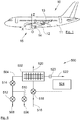
- In order to supply hot air whether for a system of air, conditioned so as to guarantee the comfort of the passengers, or for a de-icing system for de-icing the outside surfaces of an aircraft, this system includes a heat exchanger system, which is schematically illustrated in
Figure 8 . - The
heat exchanger system 500 is disposed in the vicinity of the turbojet of the aircraft and it includes aheat exchanger 502. - The
heat exchanger 502 is supplied with hot air through afirst supply pipe 504, which bleeds hot air from thehigh pressure stage 506 or at theintermediate pressure stage 508 of the turbojet, respectively through afirst valve 510 and asecond valve 512. Thefirst supply pipe 504 also includes a regulatingvalve 514, which enables regulation of the pressure at the inlet of theheat exchanger 502. - The
heat exchanger 502 is supplied with cold air by asecond supply pipe 516, which bleeds cold air from the fan duct of the turbojet. Thesecond supply pipe 516 also includes a regulatingvalve 518, which regulates the quantity of cold air introduced into theheat exchanger 502 so as to regulate the temperature of the hot air exiting theheat exchanger 502. - After having passed through the
heat exchanger 502, the cold air, which has been heated, is expelled to the outside through anevacuation pipe 520. - After having passed through the
heat exchanger 502, the hot air, which has been cooled, is directed through atransfer pipe 522 to the air management systems like the air conditioning system or the de-icing system. - The
heat exchanger system 500 includes atemperature sensor 523, which measures the temperature of the hot air exiting theheat exchanger 502 and acontrol unit 524, which controls the valves according to the temperature measured by thetemperature sensor 523 and the temperature desired for the hot air exiting theheat exchanger 502. - The
heat exchanger 502 is with cross flow, that is to say that the hot air and the cold air enter theheat exchanger 502 and exit theheat exchanger 502 along two globally perpendicular directions. - Although such a
heat exchanger system 500 gives good results, it is relatively bulky because of the crossed directions of the entering and exiting airflows. -
FR-A-2 889 298 WO-A-20007/034050 US-A-7,856,824 ,US-A-6,134,880 andUS-A-6,364,007 disclose propulsion system according to the prior art. - An aim of the present invention is to propose an aircraft propulsion system including a heat exchanger system, which is less bulky and thus enables better integration in the propulsion system.
- To that effect, an aircraft propulsion system is proposed, said aircraft propulsion system including a turbojet including compression stages and a fan duct, and a heat exchanger system, which includes:
- a heat exchanger fastened in the fan duct and including a supply connection, a transfer connection disposed aft of the heat exchanger and pneumatically connected to the supply connection through the heat exchanger, at least one scoop connection and an evacuation connection pneumatically connected to each scoop connection through the heat exchanger,
- a supply pipe, which is connected to the supply connection, and which bleeds hot air from the compression stages and supplies the heat exchanger with the hot air bled in this way,
- a transfer pipe, which is connected to the transfer connection, for transferring the hot air that has passed through the heat exchanger to an air management system of the aircraft,
- for each scoop connection, a scoop, which is connected to the scoop connection and which bleeds cold air from the fan duct and supplies the heat exchanger with the cold air bled in this way, and
- an evacuation pipe, which includes an inlet connected to the evacuation connection and an outlet, which emerges on the outside,
- The implementation of counter-current flows enables a reduction of bulkiness and hence better integration.
- According to an embodiment, the propulsion system includes a pylon with a primary structure, which supports the turbojet, the heat exchanger is fastened above the primary structure and the primary structure includes a window through which the supply pipe is assembled between the turbojet and the heat exchanger.
- Advantageously, the hot air through the heat exchanger from the supply pipe to the transfer pipe goes from forward to aft, and the cold air through the heat exchanger from each scoop to the inlet goes from aft to forward.
- According to another embodiment, the propulsion system includes a pylon with a primary structure, which supports the turbojet and in that the heat exchanger is fastened below the primary structure.
- Advantageously, the hot air through the heat exchanger from the supply pipe to the transfer pipe goes from aft to forward, and the cold air through the heat exchanger from each scoop to the inlet goes from forward to aft.
- Advantageously, each scoop includes a door, which is mobile between an open position in which it does not blank off the scoop and a closed position in which it blanks off the scoop.
- Advantageously, the heat exchanger includes a first stage and a second stage disposed aft of the first stage, first cold channels and first hot channels are placed in the first stage, second cold channels and second hot channels are placed in the second stage, the first cold channels and the second cold channels are connected together, the first hot channels and the second hot channels are connected together, forward of the first stage, the first hot channels are connected to the supply connection, forward of the first stage, the first cold channels are connected to the evacuation connection, the second stage has the shape of a truncated pyramid, which has a large base and a small base perpendicular to the first transfer direction and which has two sides inclined between the large base and the small base, the large base constitutes the junction zone between the first stage and the second stage, the small base constitutes the zone where only the second hot channels emerge and where the junction is made with the transfer connection, and each side constitutes the zone where only the second cold channels emerge and where the junction is made with one of the two scoop connections.
- Advantageously, the heat exchanger includes a first stage and a second stage disposed aft of the first stage, first cold channels and first hot channels are placed in the first stage, second cold channels and second hot channels are placed in the second stage, the first cold channels and the second cold channels are connected together, the first hot channels and the second hot channels are connected together, forward of the first stage, the first hot channels are connected to the supply connection, forward of the first stage, the first cold channels are connected to the evacuation connection, the second stage has the shape of a two-sided pyramid, which has a base perpendicular to the first transfer direction and two sides inclined from the base, the base constitutes the junction zone between the first stage and the second stage, one of the sides constitutes the zone where only the second cold channels emerge and where the junction is made with the scoop connection, and the other side constitutes the zone where only the second hot channels emerge and where the junction is made with the transfer connection.
- Advantageously, the propulsion system includes at the inlet of each second cold channel and at the outlet of each second hot channel, at least one deflector element.
- The invention also proposes an aircraft including at least one propulsion system according to one of the preceding variants.
- The aforementioned characteristics of the invention, as well as others, will emerge more clearly on reading the following description of an embodiment example, said description being made in relation to the attached drawings, among which:
-
Fig. 1 is a side view of an aircraft including a heat exchanger system according to the invention, -
Fig. 2 is a perspective view of a heat exchanger system according to the invention, -
Fig. 3 is a perspective view of a first stage of a heat exchanger of the heat exchanger system according to the invention, -
Fig. 4 is a perspective view of a second stage of a heat exchanger of the heat exchanger system according to the invention, -
Fig. 5 shows a top view of an exchanger according to a particular embodiment, -
Fig. 6 shows a top view of an exchanger according to another particular embodiment, -
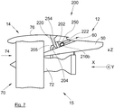
Fig. 7 shows a side view of the heat exchanger system in its environment, and -
Fig. 8 is a schematic illustration of a heat exchanger system of the state of the art. - In the description that follows, the terms relating to a position are taken with reference to an aircraft in normal flight position, that is to say, as it is illustrated on
Fig. 1 , and the positions "forward" and "aft" are taken in relation to the front and rear of the turbojet. - In the description that follows, and by convention, X is the longitudinal axis of the turbojet, which is parallel to the longitudinal axis of the aircraft, Y is the transversal axis, which is horizontal when the aircraft is on the ground, and Z is the vertical axis, which is vertical when the aircraft is on the ground, these three directions X, Y and Z being orthogonal to each other.
-
Fig. 1 shows anaircraft 10, which includes a fuselage 11, on either side of which awing 13 is fastened that supports at least onepropulsion system 15, which includes apylon 12 and a turbojet 70 (Fig. 7 ). Thepylon 12 is fastened under thewing 13 and supports theturbojet 70, which conventionally includescompression stages 72 and afan duct 74. Thepylon 12 includes a primary structure (50,Fig. 2 ), which is fastened at its upper part to the structure of thewing 13 and which supports the turbojet through different fastening points. Theprimary structure 50 is disposed above theturbojet 70 and its front edge is attached to theturbojet 70 inside thefan duct 74. - The
aircraft 10 includes an air management system like for example an air conditioning system and/or a de-icing system. - The
propulsion system 15 also includes anacelle 14, which includes afairing 76, which surrounds theturbojet 70, and an aerodynamic fairing of thepylon 12, which surrounds theprimary structure 50. -
Fig. 2 shows aheat exchanger system 200 of thepropulsion system 15, which is located on theprimary structure 50 and in thefan duct 74.Fig 7 shows theexchanger system 200 in its environment. - The
heat exchanger system 200 includes aheat exchanger 202, which is fastened above theprimary structure 50 and which includes a supply connection disposed forward of theheat exchanger 202, atransfer connection 250 disposed aft of theheat exchanger 202, at least onescoop connection 252a-b disposed aft of theheat exchanger 202 and anevacuation connection 254 disposed forward of theheat exchanger 202. - The supply connection and the
transfer connection 250 are pneumatically connected through theheat exchanger 202. Eachscoop connection 252a-b and theevacuation connection 254 are pneumatically connected through theheat exchanger 202. - The
heat exchanger system 200 includes asupply pipe 204, pneumatically connected to the supply connection and which bleeds hot air from thecompression stages 72 of theturbojet 70 and supplies theheat exchanger 202 with the hot air bled in this way. - The
heat exchanger system 200 includes atransfer pipe 222, which is pneumatically connected to thetransfer connection 250 and which transfers the hot air, which was cooled on passing through theheat exchanger 202, to the air management system of theaircraft 10. - The passage of the hot air through the
heat exchanger 202 from thesupply pipe 204 to thetransfer pipe 222 takes place along afirst transfer direction 60, which here is globally parallel to the longitudinal axis X and is here oriented from forward to aft. - For each
scoop connection 252a-b, theheat exchanger system 200 includes ascoop 216a-b, which is pneumatically connected to thescoop connection 252a-b and which bleeds cold air from the fan duct and supplies theheat exchanger 202 with the cold air bled in this way. - The
heat exchanger system 200 includes anevacuation pipe 220, which includes aninlet 220a pneumatically connected to theevacuation connection 254. Theevacuation pipe 220 also includes anoutlet 220b, which emerges on the outside through an opening in the fairing of thenacelle 14 or of thepylon 12. - Thus, after having passed through the
heat exchanger 202, the cold air, which was heated is expelled to the outside by theevacuation pipe 220 through thefairing 76. - Each
scoop 216a-b is thus disposed aft of theheat exchanger 202, that is to say, towards thetransfer pipe 222. In the embodiment of the invention presented onFig. 2 , there are twoscoops 216a-b placed to port and starboard of thetransfer pipe 222. - The passage of the cold air through the
heat exchanger 202 from eachscoop 216a-b to theinlet 220a takes place along a second transfer direction parallel to thefirst transfer direction 60, but is oriented in the opposite direction, i.e. here from aft to forward. - The
heat exchanger 202 therefore has a counter-current flow, that is to say that the hot air and the cold air enter theheat exchanger 202 and exit theheat exchanger 202 parallel to the samefirst transfer direction 60, but in opposite directions. - Such an arrangement allows space to be gained above the
primary structure 50. More specifically, thanks to the use of counterflow heat transfer which is more efficient than a crossflow heat transfer, a more compact heat exchanger is obtained, the heat exchanger can be installed closer to the pylon. - Each
scoop 216a-b includes adoor 218, which is mobile between an open position in which it does not blank off thescoop 216a-b and a closed position in which it blanks off thescoop 216a-b so as to regulate the quantity of cold air captured by saidscoop 216a-b and therefore introduced into theheat exchanger 202 in order to regulate the temperature of the hot air exiting theheat exchanger 202. Eachdoor 218 is motorized so as to ensure its movement. Eachscoop 216a-b is oriented so as to be able to capture the cold air that circulates in the fan duct. - In the embodiment of the invention presented on
Fig. 2 , theprimary structure 50 includes awindow 52 through which thesupply pipe 204 is mounted between the turbojet, which is below theprimary structure 50 and theheat exchanger 202, which is above. - As in the state of the art, the
propulsion system 15 includes valves at thesupply pipe 204 and atemperature sensor 223, which measure the temperature of the hot air exiting theheat exchanger 202. - The
doors 218, which are motorized, act as the regulatingvalve 518 for the state of the art. - The
propulsion system 15 includes a control unit, which controls the valves and the motors of thedoors 218 according to the temperature measured by thetemperature sensor 223 and the temperature desired for the hot air exiting theheat exchanger 202. - In the embodiment of the invention presented on
Fig. 2 , theoutlet 220b is oriented upwards relative to theinlet 220a. -
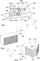
Fig. 3 shows afirst stage 302 of theheat exchanger 202 andFig. 4 shows asecond stage 402 of theheat exchanger 202, and which is positioned aft of thefirst stage 302. - The
first stage 302 is a box in which firstcold channels 304 and firsthot channels 306 are placed. In the same way, thesecond stage 402 is a box in which secondcold channels 404 and secondhot channels 406 are placed. Thefirst stage 302 and thesecond stage 402 are made of materials having a high heat transfer coefficient, such as metal for example. For eachstage cold channels hot channels cold channel hot channels - Aft of the
first stage 302, and therefore forward of thesecond stage 402, the firsthot channels 306 and the secondhot channels 406 are pneumatically connected together and are extended. Forward of thefirst stage 302, the firsthot channels 306 are pneumatically connected to the supply connection. Aft of thesecond stage 402, the secondhot channels 406 are pneumatically connected to thetransfer connection 250. The firsthot channels 306 and the secondhot channels 406 thus enable the hot air issuing from thesupply pipe 204 to flow to thetransfer pipe 222 through theheat exchanger 202. - Aft of the
first stage 302, and therefore forward of thesecond stage 402, the firstcold channels 304 and the secondcold channels 404 are pneumatically connected together and are extended. Forward of thefirst stage 302, the firstcold channels 304 are pneumatically connected to theevacuation connection 254. Aft of thesecond stage 402, the secondcold channels 404 are pneumatically connected to eachscoop connection 252a-b. The firstcold channels 304 and the secondcold channels 404 thus enable the cold air issuing from the fan duct and thescoops 216a-b to flow to theevacuation pipe 220 through theheat exchanger 202. - The
first stage 302 has the shape of a parallelepiped rectangle. - Each of the first
cold channels 304 and each of the firsthot channels 306 extend along thefirst transfer direction 60. - Each of the second
hot channels 406 extends along thefirst transfer direction 60. - The
second stage 402 has the shape of a truncated pyramid, which has alarge base 410 and asmall base 412 perpendicular to thefirst transfer direction 60 and which has twosides 414a-b inclined between thelarge base 410 and thesmall base 412. - The
large base 410 constitutes the junction zone between thefirst stage 302 and thesecond stage 402, where the secondhot channels 406 and the secondcold channels 404 emerge. - The
small base 412 constitutes the zone where only the secondhot channels 406 emerge and where the junction is made with thetransfer connection 250. The secondcold channels 404 are blanked off at thesmall base 412. - Each
side 414a-b constitutes the zone where only the secondcold channels 404 emerge and where the junction is made with one of the twoscoop connections 252a-b. The secondhot channels 406 are blanked off at eachside 414a-b. -
Fig. 5 shows a top view of a section passing through a secondcold channel 404 and in the embodiment ofFig. 5 , there is asingle scoop 216b and asingle scoop connection 252b. Thesecond stage 402 has the shape of a two-sided pyramid, which has a base 610 perpendicular to thefirst transfer direction 60 and twosides 614a-b inclined from thebase 610. - The
base 610 constitutes the junction zone between thefirst stage 302 and thesecond stage 402 where the secondhot channels 406 and the secondcold channels 404 emerge. - One of the
sides 614b constitutes the zone where only the secondcold channels 404 emerge and where the junction is made with thescoop connection 252b. The secondhot channels 406 are blanked off at theside 614b. - The
other side 614a constitutes the zone where only the secondhot channels 406 emerge (not seen onFig. 5 ) and where the junction is made with thetransfer connection 250. The secondcold channels 404 are blanked off at theside 614a. - At the junction with the
heat exchanger 202, each pipe opens out. -
Fig. 6 shows a top view of a section passing through a secondcold channel 404 and in the embodiment ofFig. 6 , there are twoscoops 216a-b and twoscoop connections 252a-b, andFig. 6 repeats the embodiment ofFig. 4 . - So as to limit pressure loss at the moment the air passes from a pipe to the heat exchanger or from the heat exchanger to a pipe, at the inlet of each second
cold channel 404 and at the outlet of each secondhot channel 406, the heat exchanger has at least onedeflector element 800, which creates suitable guidance of the flow. - In the description below, the heat exchanger is above the
primary structure 50 and the direction of the hot air through theheat exchanger 202 is from forward to aft, but in another embodiment, the exchanger is below the primary structure and the hot air is going from aft to forward and the cold air is going from forward to aft. This embodiment is particularly useful when theprimary structure 50 is disposed above theturbojet 70 and its front edge is attached above thefan duct 74.
the propulsion system being characterized in that
the supply connection is disposed forward of the heat exchanger, said at least one scoop connection is disposed aft of the heat exchanger, and the evacuation connection is disposed forward of the heat exchanger.
Claims (10)
- Propulsion system (15) of an aircraft (10), said propulsion system (15) including a turbojet including compression stages and a fan duct, and a heat exchanger system (200), which includes:- a heat exchanger (202) fastened in the fan duct and including a supply connection, a transfer connection (250) disposed aft of the heat exchanger (202) and pneumatically connected to the supply connection through the heat exchanger (202), at least one scoop connection (252a-b) and an evacuation connection (254) pneumatically connected to each scoop connection (252a-b) through the heat exchanger (202),- a supply pipe (204), which is connected to the supply connection, and which bleeds hot air from the compression stages and supplies the heat exchanger (202) with the hot air bled in this way,- a transfer pipe (222), which is connected to the transfer connection (250), for transferring the hot air that has passed through the heat exchanger (202) to an air management system of the aircraft (10),- for each scoop connection (252a-b), a scoop (216a-b), which is connected to the scoop connection (252a-b) and which bleeds cold air from the fan duct and supplies the heat exchanger (202) with the cold air bled in this way, and- an evacuation pipe (220), which includes an inlet (220a) connected to the evacuation connection (254) and an outlet (220b), which emerges on the outside,where the passage of the hot air through the heat exchanger (202) from the supply pipe (204) to the transfer pipe (222) takes place along a first transfer direction (60) and where the passage of the cold air through the heat exchanger (202) from each scoop (216a-b) to the inlet (220a) takes place along a second transfer direction parallel to the first transfer direction (60) but in the opposite direction
the propulsion system (15) being characterized in that
the supply connection is disposed forward of the heat exchanger (202), said at least one scoop connection (252a-b) is disposed aft of the heat exchanger (202), and the evacuation connection (254) is disposed forward of the heat exchanger (202). - Propulsion system (15) according to Claim 1, characterized in that it includes a pylon (12) with a primary structure (50), which supports the turbojet, in that the heat exchanger (202) is fastened above the primary structure (50) and in that the primary structure (50) includes a window (52) through which the supply pipe (204) is assembled between the turbojet and the heat exchanger (202).
- Propulsion system (15) according to Claim 2, characterized in that the hot air through the heat exchanger (202) from the supply pipe (204) to the transfer pipe (222) goes from forward to aft, and the cold air through the heat exchanger (202) from each scoop (216a-b) to the inlet (220a) goes from aft to forward.
- Propulsion system (15) according to Claim 1, characterized in that it includes a pylon (12) with a primary structure (50), which supports the turbojet and in that the heat exchanger (202) is fastened below the primary structure (50).
- Propulsion system (15) according to Claim 4, characterized in that the hot air through the heat exchanger (202) from the supply pipe (204) to the transfer pipe (222) goes from aft to forward, and the cold air through the heat exchanger (202) from each scoop (216a-b) to the inlet (220a) goes from forward to aft.
- Propulsion system (15) according to one of the preceding claims, characterized in that each scoop (216a-b) includes a door (218), which is mobile between an open position in which it does not blank off the scoop (216a-b) and a closed position in which it blanks off the scoop (216a-b).
- Propulsion system (15) according to one of the preceding claims, characterized in that the heat exchanger (202) includes a first stage (302) and a second stage (402) disposed aft of the first stage (302), in that first cold channels (304) and first hot channels (306) are placed in the first stage (302), in that second cold channels (404) and second hot channels (406) are placed in the second stage (402), in that the first cold channels (304) and the second cold channels (404) are connected together, in that the first hot channels (306) and the second hot channels (406) are connected together, in that forward of the first stage (302), the first hot channels (306) are connected to the supply connection, in that forward of the first stage (302), the first cold channels (304) are connected to the evacuation connection (254), in that the second stage (402) has the shape of a truncated pyramid, which has a large base (410) and a small base (412) perpendicular to the first transfer direction (60) and which has two sides (414a-b) inclined between the large base (410) and the small base (412), in that the large base (410) constitutes the junction zone between the first stage (302) and the second stage (402), in that the small base (412) constitutes the zone where only the second hot channels (406) emerge and where the junction is made with the transfer connection (250), and in that each side (414a-b) constitutes the zone where only the second cold channels (404) emerge and where the junction is made with one of the two scoop connections (252a-b).
- Propulsion system (15) according to one of Claims 1 to 6, characterized in that the heat exchanger (202) includes a first stage (302) and a second stage (402) disposed aft of the first stage (302), in that first cold channels (304) and first hot channels (306) are placed in the first stage (302), in that second cold channels (404) and second hot channels (406) are placed in the second stage (402), in that the first cold channels (304) and the second cold channels (404) are connected together, in that the first hot channels (306) and the second hot channels (406) are connected together, in that forward of the first stage (302), the first hot channels (306) are connected to the supply connection, in that forward of the first stage (302), the first cold channels (304) are connected to the evacuation connection (254), in that the second stage (402) has the shape of a two-sided pyramid, which has a base (610) perpendicular to the first transfer direction (60) and two sides (614a-b) inclined from the base (610), in that the base (610) constitutes the junction zone between the first stage (302) and the second stage (402), in that one of the sides (614b) constitutes the zone where only the second cold channels (404) emerge and where the junction is made with the scoop connection (252b), and in that the other side (614a) constitutes the zone where only the second hot channels (406) emerge and where the junction is made with the transfer connection (250).
- Propulsion system (15) according to one of the preceding claims, characterized in that it includes at the inlet of each second cold channel (404) and at the outlet of each second hot channel (406), at least one deflector element (800).
- Aircraft (10) including at least one propulsion system (15) according to one of the preceding claims.
Priority Applications (3)
| Application Number | Priority Date | Filing Date | Title |
|---|---|---|---|
| EP18306695.0A EP3666655B1 (en) | 2018-12-14 | 2018-12-14 | Aircraft propulsion system including a heat exchanger system |
| US16/712,232 US11215118B2 (en) | 2018-12-14 | 2019-12-12 | Aircraft propulsion system including a heat exchanger system |
| CN201911273712.XA CN111319776B (en) | 2018-12-14 | 2019-12-12 | Aircraft propulsion system and aircraft |
Applications Claiming Priority (1)
| Application Number | Priority Date | Filing Date | Title |
|---|---|---|---|
| EP18306695.0A EP3666655B1 (en) | 2018-12-14 | 2018-12-14 | Aircraft propulsion system including a heat exchanger system |
Publications (2)
| Publication Number | Publication Date |
|---|---|
| EP3666655A1 EP3666655A1 (en) | 2020-06-17 |
| EP3666655B1 true EP3666655B1 (en) | 2021-07-14 |
Family
ID=65278125
Family Applications (1)
| Application Number | Title | Priority Date | Filing Date |
|---|---|---|---|
| EP18306695.0A Active EP3666655B1 (en) | 2018-12-14 | 2018-12-14 | Aircraft propulsion system including a heat exchanger system |
Country Status (3)
| Country | Link |
|---|---|
| US (1) | US11215118B2 (en) |
| EP (1) | EP3666655B1 (en) |
| CN (1) | CN111319776B (en) |
Families Citing this family (1)
| Publication number | Priority date | Publication date | Assignee | Title |
|---|---|---|---|---|
| FR3077060A1 (en) * | 2018-01-24 | 2019-07-26 | Airbus Operations | AIRCRAFT MAT COMPRISING A COAXIAL THERMAL EXCHANGER |
Family Cites Families (7)
| Publication number | Priority date | Publication date | Assignee | Title |
|---|---|---|---|---|
| US6134880A (en) * | 1997-12-31 | 2000-10-24 | Concepts Eti, Inc. | Turbine engine with intercooler in bypass air passage |
| US6364007B1 (en) * | 2000-09-19 | 2002-04-02 | Marconi Communications, Inc. | Plastic counterflow heat exchanger |
| FR2889298B1 (en) * | 2005-07-28 | 2010-11-26 | Airbus France | THERMAL EXCHANGER, PROPELLER ASSEMBLY, AND AIRCRAFT HAVING SUCH A PROPELLER ASSEMBLY |
| FR2891313A1 (en) * | 2005-09-26 | 2007-03-30 | Airbus France Sas | DOUBLE FLOW TURBOMOTEUR HAVING A PRE-COOLER |
| FR2902830B1 (en) * | 2006-06-27 | 2008-08-08 | Airbus France Sas | TURBOREACTOR FOR AIRCRAFT |
| US7856824B2 (en) * | 2007-06-25 | 2010-12-28 | Honeywell International Inc. | Cooling systems for use on aircraft |
| FR2987602B1 (en) * | 2012-03-02 | 2014-02-28 | Aircelle Sa | TURBOMOTEUR NACELLE EQUIPPED WITH A HEAT EXCHANGER |
-
2018
- 2018-12-14 EP EP18306695.0A patent/EP3666655B1/en active Active
-
2019
- 2019-12-12 CN CN201911273712.XA patent/CN111319776B/en active Active
- 2019-12-12 US US16/712,232 patent/US11215118B2/en active Active
Also Published As
| Publication number | Publication date |
|---|---|
| US11215118B2 (en) | 2022-01-04 |
| EP3666655A1 (en) | 2020-06-17 |
| CN111319776A (en) | 2020-06-23 |
| CN111319776B (en) | 2023-02-17 |
| US20200191056A1 (en) | 2020-06-18 |
Similar Documents
| Publication | Publication Date | Title |
|---|---|---|
| EP3478581B1 (en) | Assembly and method for conditioning engine-heated air onboard an aircraft | |
| US5897079A (en) | Air curtain insulating system for aircraft cabin | |
| CN101903247B (en) | Boarding bridge with air conditioner facility | |
| US10549863B2 (en) | Actuated outlet door for aircraft high-temperature exhaust | |
| DE60313394T2 (en) | Heat exchanger for an aircraft air conditioning system and drive system with such a heat exchanger | |
| US10746100B2 (en) | Compact heat exchange device incorporated into an aircraft pylon | |
| US11408338B2 (en) | Aircraft propulsion system including a heat exchanger system | |
| EP3666655B1 (en) | Aircraft propulsion system including a heat exchanger system | |
| US9689597B2 (en) | Air-conditioning system for an aircraft, and method for an aircraft | |
| CA2551932C (en) | Air guiding flap of an aircraft comprising control of the pressure forces impinging thereon, process for adjusting the position of an air guiding flap and ram air system includingsuch an air guiding flap | |
| US11136921B2 (en) | Aircraft propulsion system including a heat exchanger system | |
| RU2111152C1 (en) | Air-conditioning system for cabin and equipment compartments of aerobatic aeroplane | |
| EP3708493B1 (en) | Aircraft propulsion system including a heat exchanger system | |
| EP3741678A1 (en) | Regulating valve for a heat exchanger system of an aircraft propulsion system | |
| US11643214B2 (en) | Cold regulating valve for a heat exchanger system of an aircraft propulsion system | |
| CN111674555B (en) | Aircraft propulsion system comprising a heat exchanger system | |
| DE102014205094A1 (en) | Aircraft cooling system, method for operating an aircraft cooling system and aircraft |
Legal Events
| Date | Code | Title | Description |
|---|---|---|---|
| PUAI | Public reference made under article 153(3) epc to a published international application that has entered the european phase |
Free format text: ORIGINAL CODE: 0009012 |
|
| STAA | Information on the status of an ep patent application or granted ep patent |
Free format text: STATUS: THE APPLICATION HAS BEEN PUBLISHED |
|
| AK | Designated contracting states |
Kind code of ref document: A1 Designated state(s): AL AT BE BG CH CY CZ DE DK EE ES FI FR GB GR HR HU IE IS IT LI LT LU LV MC MK MT NL NO PL PT RO RS SE SI SK SM TR |
|
| AX | Request for extension of the european patent |
Extension state: BA ME |
|
| STAA | Information on the status of an ep patent application or granted ep patent |
Free format text: STATUS: REQUEST FOR EXAMINATION WAS MADE |
|
| 17P | Request for examination filed |
Effective date: 20201214 |
|
| RBV | Designated contracting states (corrected) |
Designated state(s): AL AT BE BG CH CY CZ DE DK EE ES FI FR GB GR HR HU IE IS IT LI LT LU LV MC MK MT NL NO PL PT RO RS SE SI SK SM TR |
|
| GRAP | Despatch of communication of intention to grant a patent |
Free format text: ORIGINAL CODE: EPIDOSNIGR1 |
|
| STAA | Information on the status of an ep patent application or granted ep patent |
Free format text: STATUS: GRANT OF PATENT IS INTENDED |
|
| INTG | Intention to grant announced |
Effective date: 20210302 |
|
| GRAS | Grant fee paid |
Free format text: ORIGINAL CODE: EPIDOSNIGR3 |
|
| GRAA | (expected) grant |
Free format text: ORIGINAL CODE: 0009210 |
|
| STAA | Information on the status of an ep patent application or granted ep patent |
Free format text: STATUS: THE PATENT HAS BEEN GRANTED |
|
| AK | Designated contracting states |
Kind code of ref document: B1 Designated state(s): AL AT BE BG CH CY CZ DE DK EE ES FI FR GB GR HR HU IE IS IT LI LT LU LV MC MK MT NL NO PL PT RO RS SE SI SK SM TR |
|
| REG | Reference to a national code |
Ref country code: GB Ref legal event code: FG4D |
|
| REG | Reference to a national code |
Ref country code: IE Ref legal event code: FG4D |
|
| REG | Reference to a national code |
Ref country code: DE Ref legal event code: R096 Ref document number: 602018020051 Country of ref document: DE |
|
| REG | Reference to a national code |
Ref country code: AT Ref legal event code: REF Ref document number: 1410465 Country of ref document: AT Kind code of ref document: T Effective date: 20210815 |
|
| REG | Reference to a national code |
Ref country code: LT Ref legal event code: MG9D |
|
| REG | Reference to a national code |
Ref country code: NL Ref legal event code: MP Effective date: 20210714 |
|
| REG | Reference to a national code |
Ref country code: AT Ref legal event code: MK05 Ref document number: 1410465 Country of ref document: AT Kind code of ref document: T Effective date: 20210714 |
|
| PG25 | Lapsed in a contracting state [announced via postgrant information from national office to epo] |
Ref country code: SE Free format text: LAPSE BECAUSE OF FAILURE TO SUBMIT A TRANSLATION OF THE DESCRIPTION OR TO PAY THE FEE WITHIN THE PRESCRIBED TIME-LIMIT Effective date: 20210714 Ref country code: RS Free format text: LAPSE BECAUSE OF FAILURE TO SUBMIT A TRANSLATION OF THE DESCRIPTION OR TO PAY THE FEE WITHIN THE PRESCRIBED TIME-LIMIT Effective date: 20210714 Ref country code: HR Free format text: LAPSE BECAUSE OF FAILURE TO SUBMIT A TRANSLATION OF THE DESCRIPTION OR TO PAY THE FEE WITHIN THE PRESCRIBED TIME-LIMIT Effective date: 20210714 Ref country code: ES Free format text: LAPSE BECAUSE OF FAILURE TO SUBMIT A TRANSLATION OF THE DESCRIPTION OR TO PAY THE FEE WITHIN THE PRESCRIBED TIME-LIMIT Effective date: 20210714 Ref country code: FI Free format text: LAPSE BECAUSE OF FAILURE TO SUBMIT A TRANSLATION OF THE DESCRIPTION OR TO PAY THE FEE WITHIN THE PRESCRIBED TIME-LIMIT Effective date: 20210714 Ref country code: PT Free format text: LAPSE BECAUSE OF FAILURE TO SUBMIT A TRANSLATION OF THE DESCRIPTION OR TO PAY THE FEE WITHIN THE PRESCRIBED TIME-LIMIT Effective date: 20211115 Ref country code: NO Free format text: LAPSE BECAUSE OF FAILURE TO SUBMIT A TRANSLATION OF THE DESCRIPTION OR TO PAY THE FEE WITHIN THE PRESCRIBED TIME-LIMIT Effective date: 20211014 Ref country code: NL Free format text: LAPSE BECAUSE OF FAILURE TO SUBMIT A TRANSLATION OF THE DESCRIPTION OR TO PAY THE FEE WITHIN THE PRESCRIBED TIME-LIMIT Effective date: 20210714 Ref country code: AT Free format text: LAPSE BECAUSE OF FAILURE TO SUBMIT A TRANSLATION OF THE DESCRIPTION OR TO PAY THE FEE WITHIN THE PRESCRIBED TIME-LIMIT Effective date: 20210714 Ref country code: BG Free format text: LAPSE BECAUSE OF FAILURE TO SUBMIT A TRANSLATION OF THE DESCRIPTION OR TO PAY THE FEE WITHIN THE PRESCRIBED TIME-LIMIT Effective date: 20211014 Ref country code: LT Free format text: LAPSE BECAUSE OF FAILURE TO SUBMIT A TRANSLATION OF THE DESCRIPTION OR TO PAY THE FEE WITHIN THE PRESCRIBED TIME-LIMIT Effective date: 20210714 |
|
| PG25 | Lapsed in a contracting state [announced via postgrant information from national office to epo] |
Ref country code: PL Free format text: LAPSE BECAUSE OF FAILURE TO SUBMIT A TRANSLATION OF THE DESCRIPTION OR TO PAY THE FEE WITHIN THE PRESCRIBED TIME-LIMIT Effective date: 20210714 Ref country code: LV Free format text: LAPSE BECAUSE OF FAILURE TO SUBMIT A TRANSLATION OF THE DESCRIPTION OR TO PAY THE FEE WITHIN THE PRESCRIBED TIME-LIMIT Effective date: 20210714 |
|
| REG | Reference to a national code |
Ref country code: DE Ref legal event code: R097 Ref document number: 602018020051 Country of ref document: DE |
|
| PG25 | Lapsed in a contracting state [announced via postgrant information from national office to epo] |
Ref country code: DK Free format text: LAPSE BECAUSE OF FAILURE TO SUBMIT A TRANSLATION OF THE DESCRIPTION OR TO PAY THE FEE WITHIN THE PRESCRIBED TIME-LIMIT Effective date: 20210714 |
|
| PLBE | No opposition filed within time limit |
Free format text: ORIGINAL CODE: 0009261 |
|
| STAA | Information on the status of an ep patent application or granted ep patent |
Free format text: STATUS: NO OPPOSITION FILED WITHIN TIME LIMIT |
|
| PG25 | Lapsed in a contracting state [announced via postgrant information from national office to epo] |
Ref country code: SM Free format text: LAPSE BECAUSE OF FAILURE TO SUBMIT A TRANSLATION OF THE DESCRIPTION OR TO PAY THE FEE WITHIN THE PRESCRIBED TIME-LIMIT Effective date: 20210714 Ref country code: SK Free format text: LAPSE BECAUSE OF FAILURE TO SUBMIT A TRANSLATION OF THE DESCRIPTION OR TO PAY THE FEE WITHIN THE PRESCRIBED TIME-LIMIT Effective date: 20210714 Ref country code: RO Free format text: LAPSE BECAUSE OF FAILURE TO SUBMIT A TRANSLATION OF THE DESCRIPTION OR TO PAY THE FEE WITHIN THE PRESCRIBED TIME-LIMIT Effective date: 20210714 Ref country code: EE Free format text: LAPSE BECAUSE OF FAILURE TO SUBMIT A TRANSLATION OF THE DESCRIPTION OR TO PAY THE FEE WITHIN THE PRESCRIBED TIME-LIMIT Effective date: 20210714 Ref country code: CZ Free format text: LAPSE BECAUSE OF FAILURE TO SUBMIT A TRANSLATION OF THE DESCRIPTION OR TO PAY THE FEE WITHIN THE PRESCRIBED TIME-LIMIT Effective date: 20210714 Ref country code: AL Free format text: LAPSE BECAUSE OF FAILURE TO SUBMIT A TRANSLATION OF THE DESCRIPTION OR TO PAY THE FEE WITHIN THE PRESCRIBED TIME-LIMIT Effective date: 20210714 |
|
| 26N | No opposition filed |
Effective date: 20220419 |
|
| PG25 | Lapsed in a contracting state [announced via postgrant information from national office to epo] |
Ref country code: MC Free format text: LAPSE BECAUSE OF FAILURE TO SUBMIT A TRANSLATION OF THE DESCRIPTION OR TO PAY THE FEE WITHIN THE PRESCRIBED TIME-LIMIT Effective date: 20210714 Ref country code: IT Free format text: LAPSE BECAUSE OF FAILURE TO SUBMIT A TRANSLATION OF THE DESCRIPTION OR TO PAY THE FEE WITHIN THE PRESCRIBED TIME-LIMIT Effective date: 20210714 |
|
| REG | Reference to a national code |
Ref country code: CH Ref legal event code: PL |
|
| REG | Reference to a national code |
Ref country code: BE Ref legal event code: MM Effective date: 20211231 |
|
| PG25 | Lapsed in a contracting state [announced via postgrant information from national office to epo] |
Ref country code: LU Free format text: LAPSE BECAUSE OF NON-PAYMENT OF DUE FEES Effective date: 20211214 Ref country code: IE Free format text: LAPSE BECAUSE OF NON-PAYMENT OF DUE FEES Effective date: 20211214 |
|
| PG25 | Lapsed in a contracting state [announced via postgrant information from national office to epo] |
Ref country code: BE Free format text: LAPSE BECAUSE OF NON-PAYMENT OF DUE FEES Effective date: 20211231 |
|
| PG25 | Lapsed in a contracting state [announced via postgrant information from national office to epo] |
Ref country code: LI Free format text: LAPSE BECAUSE OF NON-PAYMENT OF DUE FEES Effective date: 20211231 Ref country code: CH Free format text: LAPSE BECAUSE OF NON-PAYMENT OF DUE FEES Effective date: 20211231 |
|
| PG25 | Lapsed in a contracting state [announced via postgrant information from national office to epo] |
Ref country code: CY Free format text: LAPSE BECAUSE OF FAILURE TO SUBMIT A TRANSLATION OF THE DESCRIPTION OR TO PAY THE FEE WITHIN THE PRESCRIBED TIME-LIMIT Effective date: 20210714 |
|
| PG25 | Lapsed in a contracting state [announced via postgrant information from national office to epo] |
Ref country code: HU Free format text: LAPSE BECAUSE OF FAILURE TO SUBMIT A TRANSLATION OF THE DESCRIPTION OR TO PAY THE FEE WITHIN THE PRESCRIBED TIME-LIMIT; INVALID AB INITIO Effective date: 20181214 Ref country code: GR Free format text: LAPSE BECAUSE OF FAILURE TO SUBMIT A TRANSLATION OF THE DESCRIPTION OR TO PAY THE FEE WITHIN THE PRESCRIBED TIME-LIMIT Effective date: 20210714 |
|
| PGFP | Annual fee paid to national office [announced via postgrant information from national office to epo] |
Ref country code: GB Payment date: 20231220 Year of fee payment: 6 |
|
| PGFP | Annual fee paid to national office [announced via postgrant information from national office to epo] |
Ref country code: FR Payment date: 20231222 Year of fee payment: 6 Ref country code: DE Payment date: 20231214 Year of fee payment: 6 |