EP4371805A1 - Battery electric vehicle and charging control method for storage battery of battery electric vehicle - Google Patents
Battery electric vehicle and charging control method for storage battery of battery electric vehicle Download PDFInfo
- Publication number
- EP4371805A1 EP4371805A1 EP23203028.8A EP23203028A EP4371805A1 EP 4371805 A1 EP4371805 A1 EP 4371805A1 EP 23203028 A EP23203028 A EP 23203028A EP 4371805 A1 EP4371805 A1 EP 4371805A1
- Authority
- EP
- European Patent Office
- Prior art keywords
- rotational angle
- charging
- motor
- charging current
- torque
- Prior art date
- Legal status (The legal status is an assumption and is not a legal conclusion. Google has not performed a legal analysis and makes no representation as to the accuracy of the status listed.)
- Withdrawn
Links
Images

Classifications
-
- B—PERFORMING OPERATIONS; TRANSPORTING
- B60—VEHICLES IN GENERAL
- B60L—PROPULSION OF ELECTRICALLY-PROPELLED VEHICLES; SUPPLYING ELECTRIC POWER FOR AUXILIARY EQUIPMENT OF ELECTRICALLY-PROPELLED VEHICLES; ELECTRODYNAMIC BRAKE SYSTEMS FOR VEHICLES IN GENERAL; MAGNETIC SUSPENSION OR LEVITATION FOR VEHICLES; MONITORING OPERATING VARIABLES OF ELECTRICALLY-PROPELLED VEHICLES; ELECTRIC SAFETY DEVICES FOR ELECTRICALLY-PROPELLED VEHICLES
- B60L53/00—Methods of charging batteries, specially adapted for electric vehicles; Charging stations or on-board charging equipment therefor; Exchange of energy storage elements in electric vehicles
- B60L53/20—Methods of charging batteries, specially adapted for electric vehicles; Charging stations or on-board charging equipment therefor; Exchange of energy storage elements in electric vehicles characterised by converters located in the vehicle
- B60L53/24—Using the vehicle's propulsion converter for charging
-
- B—PERFORMING OPERATIONS; TRANSPORTING
- B60—VEHICLES IN GENERAL
- B60L—PROPULSION OF ELECTRICALLY-PROPELLED VEHICLES; SUPPLYING ELECTRIC POWER FOR AUXILIARY EQUIPMENT OF ELECTRICALLY-PROPELLED VEHICLES; ELECTRODYNAMIC BRAKE SYSTEMS FOR VEHICLES IN GENERAL; MAGNETIC SUSPENSION OR LEVITATION FOR VEHICLES; MONITORING OPERATING VARIABLES OF ELECTRICALLY-PROPELLED VEHICLES; ELECTRIC SAFETY DEVICES FOR ELECTRICALLY-PROPELLED VEHICLES
- B60L50/00—Electric propulsion with power supplied within the vehicle
- B60L50/50—Electric propulsion with power supplied within the vehicle using propulsion power supplied by batteries or fuel cells
- B60L50/60—Electric propulsion with power supplied within the vehicle using propulsion power supplied by batteries or fuel cells using power supplied by batteries
-
- B—PERFORMING OPERATIONS; TRANSPORTING
- B60—VEHICLES IN GENERAL
- B60L—PROPULSION OF ELECTRICALLY-PROPELLED VEHICLES; SUPPLYING ELECTRIC POWER FOR AUXILIARY EQUIPMENT OF ELECTRICALLY-PROPELLED VEHICLES; ELECTRODYNAMIC BRAKE SYSTEMS FOR VEHICLES IN GENERAL; MAGNETIC SUSPENSION OR LEVITATION FOR VEHICLES; MONITORING OPERATING VARIABLES OF ELECTRICALLY-PROPELLED VEHICLES; ELECTRIC SAFETY DEVICES FOR ELECTRICALLY-PROPELLED VEHICLES
- B60L53/00—Methods of charging batteries, specially adapted for electric vehicles; Charging stations or on-board charging equipment therefor; Exchange of energy storage elements in electric vehicles
- B60L53/10—Methods of charging batteries, specially adapted for electric vehicles; Charging stations or on-board charging equipment therefor; Exchange of energy storage elements in electric vehicles characterised by the energy transfer between the charging station and the vehicle
- B60L53/14—Conductive energy transfer
- B60L53/16—Connectors, e.g. plugs or sockets, specially adapted for charging electric vehicles
-
- B—PERFORMING OPERATIONS; TRANSPORTING
- B60—VEHICLES IN GENERAL
- B60L—PROPULSION OF ELECTRICALLY-PROPELLED VEHICLES; SUPPLYING ELECTRIC POWER FOR AUXILIARY EQUIPMENT OF ELECTRICALLY-PROPELLED VEHICLES; ELECTRODYNAMIC BRAKE SYSTEMS FOR VEHICLES IN GENERAL; MAGNETIC SUSPENSION OR LEVITATION FOR VEHICLES; MONITORING OPERATING VARIABLES OF ELECTRICALLY-PROPELLED VEHICLES; ELECTRIC SAFETY DEVICES FOR ELECTRICALLY-PROPELLED VEHICLES
- B60L53/00—Methods of charging batteries, specially adapted for electric vehicles; Charging stations or on-board charging equipment therefor; Exchange of energy storage elements in electric vehicles
- B60L53/20—Methods of charging batteries, specially adapted for electric vehicles; Charging stations or on-board charging equipment therefor; Exchange of energy storage elements in electric vehicles characterised by converters located in the vehicle
- B60L53/22—Constructional details or arrangements of charging converters specially adapted for charging electric vehicles
-
- B—PERFORMING OPERATIONS; TRANSPORTING
- B60—VEHICLES IN GENERAL
- B60L—PROPULSION OF ELECTRICALLY-PROPELLED VEHICLES; SUPPLYING ELECTRIC POWER FOR AUXILIARY EQUIPMENT OF ELECTRICALLY-PROPELLED VEHICLES; ELECTRODYNAMIC BRAKE SYSTEMS FOR VEHICLES IN GENERAL; MAGNETIC SUSPENSION OR LEVITATION FOR VEHICLES; MONITORING OPERATING VARIABLES OF ELECTRICALLY-PROPELLED VEHICLES; ELECTRIC SAFETY DEVICES FOR ELECTRICALLY-PROPELLED VEHICLES
- B60L53/00—Methods of charging batteries, specially adapted for electric vehicles; Charging stations or on-board charging equipment therefor; Exchange of energy storage elements in electric vehicles
- B60L53/60—Monitoring or controlling charging stations
- B60L53/62—Monitoring or controlling charging stations in response to charging parameters, e.g. current, voltage or electrical charge
-
- B—PERFORMING OPERATIONS; TRANSPORTING
- B60—VEHICLES IN GENERAL
- B60L—PROPULSION OF ELECTRICALLY-PROPELLED VEHICLES; SUPPLYING ELECTRIC POWER FOR AUXILIARY EQUIPMENT OF ELECTRICALLY-PROPELLED VEHICLES; ELECTRODYNAMIC BRAKE SYSTEMS FOR VEHICLES IN GENERAL; MAGNETIC SUSPENSION OR LEVITATION FOR VEHICLES; MONITORING OPERATING VARIABLES OF ELECTRICALLY-PROPELLED VEHICLES; ELECTRIC SAFETY DEVICES FOR ELECTRICALLY-PROPELLED VEHICLES
- B60L53/00—Methods of charging batteries, specially adapted for electric vehicles; Charging stations or on-board charging equipment therefor; Exchange of energy storage elements in electric vehicles
- B60L53/60—Monitoring or controlling charging stations
- B60L53/66—Data transfer between charging stations and vehicles
-
- H—ELECTRICITY
- H02—GENERATION; CONVERSION OR DISTRIBUTION OF ELECTRIC POWER
- H02J—ELECTRIC POWER NETWORKS; CIRCUIT ARRANGEMENTS OR SYSTEMS FOR SUPPLYING OR DISTRIBUTING ELECTRIC POWER; SYSTEMS FOR STORING ELECTRIC ENERGY
- H02J7/00—Circuit arrangements for charging or discharging batteries or for supplying loads from batteries
- H02J7/14—Circuit arrangements for charging or discharging batteries or for supplying loads from batteries for charging batteries from dynamo-electric generators driven at varying speed, e.g. on vehicle
- H02J7/1446—Circuit arrangements for charging or discharging batteries or for supplying loads from batteries for charging batteries from dynamo-electric generators driven at varying speed, e.g. on vehicle in response to parameters of a vehicle
-
- H—ELECTRICITY
- H02—GENERATION; CONVERSION OR DISTRIBUTION OF ELECTRIC POWER
- H02P—CONTROL OR REGULATION OF ELECTRIC MOTORS, ELECTRIC GENERATORS OR DYNAMO-ELECTRIC CONVERTERS; CONTROLLING TRANSFORMERS, REACTORS OR CHOKE COILS
- H02P23/00—Arrangements or methods for the control of AC motors characterised by a control method other than vector control
- H02P23/14—Estimation or adaptation of motor parameters, e.g. rotor time constant, flux, speed, current or voltage
-
- H—ELECTRICITY
- H02—GENERATION; CONVERSION OR DISTRIBUTION OF ELECTRIC POWER
- H02P—CONTROL OR REGULATION OF ELECTRIC MOTORS, ELECTRIC GENERATORS OR DYNAMO-ELECTRIC CONVERTERS; CONTROLLING TRANSFORMERS, REACTORS OR CHOKE COILS
- H02P27/00—Arrangements or methods for the control of AC motors characterised by the kind of supply voltage
- H02P27/04—Arrangements or methods for the control of AC motors characterised by the kind of supply voltage using variable-frequency supply voltage, e.g. inverter or converter supply voltage
- H02P27/06—Arrangements or methods for the control of AC motors characterised by the kind of supply voltage using variable-frequency supply voltage, e.g. inverter or converter supply voltage using DC to AC converters or inverters
-
- B—PERFORMING OPERATIONS; TRANSPORTING
- B60—VEHICLES IN GENERAL
- B60L—PROPULSION OF ELECTRICALLY-PROPELLED VEHICLES; SUPPLYING ELECTRIC POWER FOR AUXILIARY EQUIPMENT OF ELECTRICALLY-PROPELLED VEHICLES; ELECTRODYNAMIC BRAKE SYSTEMS FOR VEHICLES IN GENERAL; MAGNETIC SUSPENSION OR LEVITATION FOR VEHICLES; MONITORING OPERATING VARIABLES OF ELECTRICALLY-PROPELLED VEHICLES; ELECTRIC SAFETY DEVICES FOR ELECTRICALLY-PROPELLED VEHICLES
- B60L2240/00—Control parameters of input or output; Target parameters
- B60L2240/40—Drive Train control parameters
- B60L2240/42—Drive Train control parameters related to electric machines
-
- B—PERFORMING OPERATIONS; TRANSPORTING
- B60—VEHICLES IN GENERAL
- B60L—PROPULSION OF ELECTRICALLY-PROPELLED VEHICLES; SUPPLYING ELECTRIC POWER FOR AUXILIARY EQUIPMENT OF ELECTRICALLY-PROPELLED VEHICLES; ELECTRODYNAMIC BRAKE SYSTEMS FOR VEHICLES IN GENERAL; MAGNETIC SUSPENSION OR LEVITATION FOR VEHICLES; MONITORING OPERATING VARIABLES OF ELECTRICALLY-PROPELLED VEHICLES; ELECTRIC SAFETY DEVICES FOR ELECTRICALLY-PROPELLED VEHICLES
- B60L2240/00—Control parameters of input or output; Target parameters
- B60L2240/40—Drive Train control parameters
- B60L2240/42—Drive Train control parameters related to electric machines
- B60L2240/423—Torque
-
- Y—GENERAL TAGGING OF NEW TECHNOLOGICAL DEVELOPMENTS; GENERAL TAGGING OF CROSS-SECTIONAL TECHNOLOGIES SPANNING OVER SEVERAL SECTIONS OF THE IPC; TECHNICAL SUBJECTS COVERED BY FORMER USPC CROSS-REFERENCE ART COLLECTIONS [XRACs] AND DIGESTS
- Y02—TECHNOLOGIES OR APPLICATIONS FOR MITIGATION OR ADAPTATION AGAINST CLIMATE CHANGE
- Y02T—CLIMATE CHANGE MITIGATION TECHNOLOGIES RELATED TO TRANSPORTATION
- Y02T10/00—Road transport of goods or passengers
- Y02T10/60—Other road transportation technologies with climate change mitigation effect
- Y02T10/70—Energy storage systems for electromobility, e.g. batteries
-
- Y—GENERAL TAGGING OF NEW TECHNOLOGICAL DEVELOPMENTS; GENERAL TAGGING OF CROSS-SECTIONAL TECHNOLOGIES SPANNING OVER SEVERAL SECTIONS OF THE IPC; TECHNICAL SUBJECTS COVERED BY FORMER USPC CROSS-REFERENCE ART COLLECTIONS [XRACs] AND DIGESTS
- Y02—TECHNOLOGIES OR APPLICATIONS FOR MITIGATION OR ADAPTATION AGAINST CLIMATE CHANGE
- Y02T—CLIMATE CHANGE MITIGATION TECHNOLOGIES RELATED TO TRANSPORTATION
- Y02T10/00—Road transport of goods or passengers
- Y02T10/60—Other road transportation technologies with climate change mitigation effect
- Y02T10/7072—Electromobility specific charging systems or methods for batteries, ultracapacitors, supercapacitors or double-layer capacitors
-
- Y—GENERAL TAGGING OF NEW TECHNOLOGICAL DEVELOPMENTS; GENERAL TAGGING OF CROSS-SECTIONAL TECHNOLOGIES SPANNING OVER SEVERAL SECTIONS OF THE IPC; TECHNICAL SUBJECTS COVERED BY FORMER USPC CROSS-REFERENCE ART COLLECTIONS [XRACs] AND DIGESTS
- Y02—TECHNOLOGIES OR APPLICATIONS FOR MITIGATION OR ADAPTATION AGAINST CLIMATE CHANGE
- Y02T—CLIMATE CHANGE MITIGATION TECHNOLOGIES RELATED TO TRANSPORTATION
- Y02T90/00—Enabling technologies or technologies with a potential or indirect contribution to GHG emissions mitigation
- Y02T90/10—Technologies relating to charging of electric vehicles
- Y02T90/14—Plug-in electric vehicles
Definitions
- the present disclosure relates to a battery electric vehicle that is equipped with a storage battery and that travels using electricity as driving power, and to a charging control method for the storage battery.
- the present disclosure provides a battery electric vehicle and a charging control method for a storage battery of the battery electric vehicle that can suppress vehicle behavior by controlling output of the charging current at the time of performing charging.
- a first aspect of the present disclosure is a battery electric vehicle.
- a battery electric vehicle includes a storage battery, an electric power conversion device that is electrically connected to the storage battery, a motor that is electrically connected to the electric power conversion device, a connector that is electrically connected to a neutral point of the motor and that is configured to receive connection of a charging plug of a charging station, a rotational angle sensor that is configured to measure a rotational angle of the motor, and a control device that is configured to communicate with the charging station in a state in which the charging plug is connected to the connector, and to control the charging station based on a measurement result of the rotational angle sensor.
- the control device is configured to control the charging station such that a predetermined charging current is output when the rotational angle of the motor is a torque non-generating rotational angle at which no torque is generated in the motor at a time of supplying a charging current to the neutral point.
- the control device is configured to control the charging station such that a charging current that is smaller than the predetermined charging current is output when the rotational angle of the motor is not the torque non-generating rotational angle.
- control device may be configured to control the charging station such that the greater a difference between the rotational angle of the motor and the torque non-generating rotational angle is, a smaller charging current is output.
- a second aspect of the present disclosure is a charging control method for a storage battery of a battery electric vehicle.
- a battery electric vehicle that includes a storage battery, an electric power conversion device that is electrically connected to the storage battery, a motor that is electrically connected to the electric power conversion device, a connector that is electrically connected to a neutral point of the motor and that is configured to receive connection of a charging plug of a charging station, a rotational angle sensor that is configured to measure a rotational angle of the motor, and a control device that is configured to communicate with the charging station in a state in which the charging plug is connected to the connector, in which charging of the storage battery is controlled by the control device.
- This charging control method causes the control device to execute measuring the rotational angle of the motor, determining whether the rotational angle is a torque non-generating rotational angle at which no torque is generated in the motor at a time of supplying a charging current to the neutral point, controlling the charging station to output a predetermined charging current when the rotational angle is the torque non-generating rotational angle, and controlling the charging station such that a charging current that is smaller than the predetermined charging current is output when the rotational angle is not the torque non-generating rotational angle.
- the control device may execute controlling the charging station such that the greater a difference between the rotational angle of the motor and the torque non-generating rotational angle is, a smaller charging current is output.
- the vehicle when charging the battery electric vehicle, the vehicle can be suppressed from starting to move.
- the charging circuit 1 includes a storage battery 2, an electric power conversion device 3, a motor 4, a connector 5, a rotational angle sensor 6, and current sensors 7a, 7b, 7c and 7d.
- the charging circuit 1 is also connected to a control device 8.
- the charging circuit 1 is connected to a charging station 9 which is a direct current power source, and charges the storage battery 2.
- the charging circuit 1 receives supply of charging current from the charging station 9 connected to the connector 5, boosts voltage of the charging current by the motor 4 and the electric power conversion device 3, and supplies the boosted charging current to the storage battery. 2.
- the charging current that is output from the charging station 9 is controlled by the control device 8.
- the storage battery 2 is formed by consecutively connecting a plurality of storage cells.
- the storage battery 2 is a battery that is rechargeable, such as a lithium-ion battery.
- the electric power conversion device 3 is electrically connected to the storage battery 2 and the motor 4. While the vehicle is traveling, the electric power conversion device 3 converts current stored in the storage battery 2 from direct current to alternating current, and supplies the alternating current to the motor 4. While charging, the electric power conversion device 3 operates collaboratively with the motor 4 to boost the charging current supplied from the charging station 9.
- the motor 4 generates torque by being supplied with electric power from the storage battery 2 while the vehicle is traveling, and uses the generated torque as a motive power source to run the vehicle. While charging, the motor 4 is electrically connected to the charging station 9 via the connector 5 and is supplied with the charging current from the charging station 9.
- the motor 4 has coils of three phases, and when alternating current flows into each coil, a magnetic field that changes over time is generated inside the coils.
- the magnetic field generates motive power to rotate in a certain direction, whereby the motor 4 functions.
- the charging current is supplied to a neutral point of the motor 4.
- the charging current that is supplied is supplied to the electric power conversion device 3 through the coils.
- the charging current supplied to the neutral point flows through the coils, there are cases in which torque is generated in the motor 4, depending on a rotational angle of the motor 4, i.e., a rotational angle of a rotor with respect to a stator.
- the connector 5 is equipment for electrically connecting the charging station 9 and the charging circuit 1. Specifically, the connector 5 is a device for connecting a charging plug 10 provided to the charging station 9 and the charging circuit 1, to enable charging by the charging station 9. Further, the connector 5 is connected to the neutral point of the motor 4.
- the rotational angle sensor 6 is connected to the motor 4 and measures the rotational angle of the motor 4. The rotational angle sensor 6 also transmits information regarding the measured rotational angle of the motor 4 to the control device 8.
- the current sensors 7a to 7d are connected to the neutral point of the motor 4, and can be classified into a neutral point current sensor 7a for measuring the current flowing at the neutral point, and phase current sensors 7b, 7c, and 7d for measuring the current flowing through each phase of the motor 4.
- Each current sensor 7a to 7d transmits information regarding the current values that are measured to the control device 8.
- the control device 8 communicates with the charging station 9, and controls magnitude of the charging current output by the charging station 9. Charging by the charging station 9 is performed in a state in which the charging plug 10 is connected to the connector 5 of the charging circuit 1. Communication between the control device 8 and the charging station 9 is performed by, for example, a communication cable. The charging plug 10 and the connector 5 can be used for connection of the communication cable.
- Control of the charging current output from the charging station 9 by the control device 8 is performed based on results of the measurement performed by the rotational angle sensor 6.
- the control device 8 performs the following two types of control, i.e., first and second control, with regard to the charging station 9.
- the first control is performed when the rotational angle of the motor 4 is a torque non-generating rotational angle, and the control device 8 controls the charging station 9 to output a predetermined charging current.
- a torque non-generating rotational angle is defined as a rotational angle at which no torque is generated in the motor 4 when charging current is supplied to the neutral point of the motor 4.
- the second control is performed when the rotational angle of the motor 4 is not a torque non-generating rotational angle, and the control device 8 controls the charging station 9 to output a charging current that is smaller than the predetermined charging current.
- FIG. 2A is a graph showing a relation among magnitude of charging current during charging, behavior of the vehicle, magnitude of generated torque, and elapsed time, according to the related art.
- FIG. 2B is a graph showing a relation among the magnitude of the charging current during charging, the behavior of the vehicle, the magnitude of the generated torque, and elapsed time, according to the embodiment.
- the horizontal axis of the graph indicates elapsed time.
- the vertical axis indicates the magnitude of each parameter.
- line 11a indicates the magnitude of the charging current.
- line 12a indicates the vehicle behavior, i.e., the magnitude of acceleration generated in the vehicle.
- line 13a indicates the magnitude of the torque generated by the motor 4.
- the charging station 9 outputs a predetermined charging current immediately after starting charging, to charge the battery electric vehicle 100. Therefore, as the charging current is supplied, torque is generated in the motor 4, and the vehicle behavior of the battery electric vehicle 100 may become irregular. That is to say, the battery electric vehicle 100 may start moving due to a sudden increase in the charging current at the start of charging.
- the vertical axis and the horizontal axis in FIG. 2B respectively indicate the magnitude of each parameter, and the elapsed time, in the same way as in FIG. 2A .
- line 11b indicates the magnitude of the charging current
- line 12b indicates the magnitude of the vehicle behavior
- line 13b indicates the magnitude of the torque generated by the motor 4.
- the charging station 9 upon receiving a request from the control device 8, gradually increases the charging current.
- the torque generated by the motor 4 is suppressed as compared to line 13a in FIG. 2A according to the related art. Suppressing the torque generated by the motor 4 also suppresses the behavior of the vehicle, and as a result, the battery electric vehicle 100 does not readily move during charging.
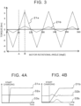
- FIG. 3 shows a comparison between the related art and the present embodiment regarding a relation between the rotational angle of the motor 4 and the magnitude of generated torque.
- line 21a in FIG. 3 shows the relation between the rotational angle of the motor 4 and the magnitude of the generated torque according to the related art.
- Line 21b in FIG. 3 shows the relation between the rotational angle of the motor 4 and the magnitude of the generated torque according to the present embodiment.
- a rotational angle of the motor 4 reaches a rotational angle A at which the generated torque becomes 0, at intervals of 60° starting from 0°, and reaches a rotational angle B at which the generated torque peaks, at intervals of 60° starting from 30°.
- the rotational angle A is a torque non-generating rotational angle.
- the predetermined charging current is supplied to the neutral point regardless of whether the rotational angle is the torque non-generating rotational angle. Accordingly, the magnitude of the torque generated by the motor 4 increases as the distance from the torque non-generating rotational angle increases, and excessive torque is generated at the rotational angle B that is the farthest from the torque non-generating rotational angle.
- the predetermined charging current is output from the charging station 9 at the rotational angle A, which is the torque non-generating rotational angle.
- the rotational angle A which is the torque non-generating rotational angle.
- the charging station 9 outputs a charging current smaller than the predetermined charging current. Suppressing the charging current so as to be lower than the predetermined charging current suppresses the magnitude of the torque generated by the motor 4, even at rotational angles other than the torque non-generating rotational angle.
- FIGS. 4A and 4B show changes over time in the magnitude of the charging current, the magnitude of the generated torque, and the vehicle behavior, in accordance with the rotational angle, according to the present embodiment.
- FIG. 4A shows control that is executed by the control device 8 when charging is started with the rotational angle of the motor 4 at the torque non-generating rotational angle (rotational angle A shown in FIG. 3 ).
- Line 31a indicates the magnitude of the charging current
- line 32a indicates the vehicle behavior
- line 33a indicates the generated torque.
- the generated torque is 0 at the torque non-generating rotational angle, and accordingly the control device 8 controls the charging station 9 to output the predetermined charging current.
- FIG. 4B shows control that is executed by the control device 8 when charging is started with the rotational angle of the motor 4 at an intermediate rotational angle between two torque non-generating rotational angles that are adjacent (rotational angle B shown in FIG. 3 ).
- Line 31b indicates the magnitude of the charging current
- line 32b indicates the vehicle behavior
- line 33b indicates the generated torque. The torque generated at a halfway rotational angle between the torque non-generating rotational angles is greatest, and accordingly the control device 8 controls the charging station 9 to output a charging current smaller than the predetermined charging current.
- control device 8 controls the charging station 9 to output a smaller charging current the greater the difference between the rotational angle of the motor 4 and the torque non-generating rotational angle is. That is to say, in the example shown in FIG. 3 , the control device 8 reduces the charging current output by the charging station 9 from the rotational angle A to the rotational angle B. Accordingly, the behavior of the vehicle during charging can be further suppressed while ensuring a certain amount of supply of charging current.
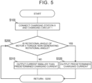
- FIG. 5 shows a charging control method for the storage battery 2 of the battery electric vehicle 100 according to the present embodiment.
- step S100 the charging station 9 and the charging circuit 1 are connected by the charging plug 10 and the connector 5.
- step S200 the control device 8 determines whether the rotational angle of the motor 4 is a torque non-generating rotational angle. When the rotational angle of the motor 4 is not the torque non-generating rotational angle, the processing advances to step S310. When the rotational angle of the motor 4 is the torque non-generating rotational angle, the processing advances to step S320.
- step S310 the rotational angle of the motor 4 is not the torque non-generating rotational angle, and accordingly the control device 8 controls the charging station 9 so that a charging current smaller than the predetermined charging current is output.
- the processing returns to step S200.
- step S320 the rotational angle of the motor 4 is the torque non-generating rotational angle, and accordingly the control device 8 controls the charging station 9 so that the predetermined charging current is output.
- the processing returns to step S200.
- the charging current output from the charging station 9 is controlled based on the rotational angle of the motor 4, thereby suppressing movement of the battery electric vehicle 100 during charging.
Landscapes
- Engineering & Computer Science (AREA)
- Power Engineering (AREA)
- Transportation (AREA)
- Mechanical Engineering (AREA)
- Life Sciences & Earth Sciences (AREA)
- Sustainable Development (AREA)
- Sustainable Energy (AREA)
- Electric Propulsion And Braking For Vehicles (AREA)
- Charge And Discharge Circuits For Batteries Or The Like (AREA)
Abstract
A battery electric vehicle (100) includes a storage battery (2), an electric power conversion device (3), a motor (4), a connector (5), a rotational angle sensor (6), and a control device (8). The control device (8) is configured to control a charging station (9) such that a predetermined charging current is output when a rotational angle of the motor (4) is a torque non-generating rotational angle at which no torque is generated in the motor (4) at a time of supplying a charging current to a neutral point of the motor (4). The control device (8) is configured to control the charging station (9) such that a charging current that is smaller than the predetermined charging current is output when the rotational angle of the motor (4) is not the torque non-generating rotational angle.
Description
- The present disclosure relates to a battery electric vehicle that is equipped with a storage battery and that travels using electricity as driving power, and to a charging control method for the storage battery.
-
Japanese Patent No. 5735782 JP 5735782 B JP 5735782 B - When a charging current is supplied to the neutral point of the drive motor as disclosed in
JP 5735782 B - Accordingly, the present disclosure provides a battery electric vehicle and a charging control method for a storage battery of the battery electric vehicle that can suppress vehicle behavior by controlling output of the charging current at the time of performing charging.
- A first aspect of the present disclosure is a battery electric vehicle. A battery electric vehicle includes a storage battery, an electric power conversion device that is electrically connected to the storage battery, a motor that is electrically connected to the electric power conversion device, a connector that is electrically connected to a neutral point of the motor and that is configured to receive connection of a charging plug of a charging station, a rotational angle sensor that is configured to measure a rotational angle of the motor, and a control device that is configured to communicate with the charging station in a state in which the charging plug is connected to the connector, and to control the charging station based on a measurement result of the rotational angle sensor. The control device is configured to control the charging station such that a predetermined charging current is output when the rotational angle of the motor is a torque non-generating rotational angle at which no torque is generated in the motor at a time of supplying a charging current to the neutral point. The control device is configured to control the charging station such that a charging current that is smaller than the predetermined charging current is output when the rotational angle of the motor is not the torque non-generating rotational angle.
- In the battery electric vehicle, the control device may be configured to control the charging station such that the greater a difference between the rotational angle of the motor and the torque non-generating rotational angle is, a smaller charging current is output.
- A second aspect of the present disclosure is a charging control method for a storage battery of a battery electric vehicle. In this charging control method, in a battery electric vehicle that includes a storage battery, an electric power conversion device that is electrically connected to the storage battery, a motor that is electrically connected to the electric power conversion device, a connector that is electrically connected to a neutral point of the motor and that is configured to receive connection of a charging plug of a charging station, a rotational angle sensor that is configured to measure a rotational angle of the motor, and a control device that is configured to communicate with the charging station in a state in which the charging plug is connected to the connector, in which charging of the storage battery is controlled by the control device. This charging control method causes the control device to execute measuring the rotational angle of the motor, determining whether the rotational angle is a torque non-generating rotational angle at which no torque is generated in the motor at a time of supplying a charging current to the neutral point, controlling the charging station to output a predetermined charging current when the rotational angle is the torque non-generating rotational angle, and controlling the charging station such that a charging current that is smaller than the predetermined charging current is output when the rotational angle is not the torque non-generating rotational angle.
- In the charging control method, when the rotational angle is not the torque non-generating rotational angle, the control device may execute controlling the charging station such that the greater a difference between the rotational angle of the motor and the torque non-generating rotational angle is, a smaller charging current is output.
- According to the present disclosure, when charging the battery electric vehicle, the vehicle can be suppressed from starting to move.
- Features, advantages, and technical and industrial significance of exemplary embodiments of the invention will be described below with reference to the accompanying drawings, in which like signs denote like elements, and wherein:
-
FIG. 1 is a diagram of a charging circuit installed inside a battery electric vehicle according to an embodiment; -
FIG. 2A is a graph showing a relation among magnitude of charging current during charging, behavior of the vehicle, magnitude of generated torque, and elapsed time, according to related art; -
FIG. 2B is a graph showing a relation among magnitude of charging current during charging, behavior of the vehicle, magnitude of generated torque, and elapsed time, according to the embodiment; -
FIG. 3 shows a comparison between the related art and the embodiment regarding a relation between rotational angle of a motor and the magnitude of generated torque; -
FIG. 4A shows control performed by a control device, which is executed at the time of starting charging when the rotational angle of the motor is at a torque non-generating rotational angle, with regard to temporal change of the magnitude of the charging current, the magnitude of torque that is generated, and the behavior of the vehicle, in accordance with the rotational angle of the motor, according to the embodiment; -
FIG. 4B shows control performed by the control device, which is executed at the time of starting charging when the rotational angle of the motor is at a halfway rotational angle between two torque non-generating rotational angles that are adjacent, with regard to temporal change of the magnitude of the charging current, the magnitude of torque that is generated, and the behavior of the vehicle, in accordance with the rotational angle of the motor, according to the embodiment; and -
FIG. 5 shows a charging control method for a storage battery of the battery electric vehicle according to the embodiment. -
FIG. 1 is a diagram of acharging circuit 1 installed inside a batteryelectric vehicle 100 according to an embodiment. - The
charging circuit 1 includes astorage battery 2, an electricpower conversion device 3, amotor 4, aconnector 5, arotational angle sensor 6, andcurrent sensors charging circuit 1 is also connected to acontrol device 8. At the time of charging, thecharging circuit 1 is connected to acharging station 9 which is a direct current power source, and charges thestorage battery 2. Specifically, thecharging circuit 1 receives supply of charging current from thecharging station 9 connected to theconnector 5, boosts voltage of the charging current by themotor 4 and the electricpower conversion device 3, and supplies the boosted charging current to the storage battery. 2. The charging current that is output from thecharging station 9 is controlled by thecontrol device 8. - The
storage battery 2 is formed by consecutively connecting a plurality of storage cells. Specifically, thestorage battery 2 is a battery that is rechargeable, such as a lithium-ion battery. - The electric
power conversion device 3 is electrically connected to thestorage battery 2 and themotor 4. While the vehicle is traveling, the electricpower conversion device 3 converts current stored in thestorage battery 2 from direct current to alternating current, and supplies the alternating current to themotor 4. While charging, the electricpower conversion device 3 operates collaboratively with themotor 4 to boost the charging current supplied from thecharging station 9. - The
motor 4 generates torque by being supplied with electric power from thestorage battery 2 while the vehicle is traveling, and uses the generated torque as a motive power source to run the vehicle. While charging, themotor 4 is electrically connected to thecharging station 9 via theconnector 5 and is supplied with the charging current from thecharging station 9. - The
motor 4 has coils of three phases, and when alternating current flows into each coil, a magnetic field that changes over time is generated inside the coils. The magnetic field generates motive power to rotate in a certain direction, whereby themotor 4 functions. Also, while charging, the charging current is supplied to a neutral point of themotor 4. The charging current that is supplied is supplied to the electricpower conversion device 3 through the coils. When the charging current supplied to the neutral point flows through the coils, there are cases in which torque is generated in themotor 4, depending on a rotational angle of themotor 4, i.e., a rotational angle of a rotor with respect to a stator. - The
connector 5 is equipment for electrically connecting thecharging station 9 and thecharging circuit 1. Specifically, theconnector 5 is a device for connecting acharging plug 10 provided to thecharging station 9 and thecharging circuit 1, to enable charging by thecharging station 9. Further, theconnector 5 is connected to the neutral point of themotor 4. - The
rotational angle sensor 6 is connected to themotor 4 and measures the rotational angle of themotor 4. Therotational angle sensor 6 also transmits information regarding the measured rotational angle of themotor 4 to thecontrol device 8. - The
current sensors 7a to 7d are connected to the neutral point of themotor 4, and can be classified into a neutral pointcurrent sensor 7a for measuring the current flowing at the neutral point, and phasecurrent sensors motor 4. Eachcurrent sensor 7a to 7d transmits information regarding the current values that are measured to thecontrol device 8. - The
control device 8 communicates with thecharging station 9, and controls magnitude of the charging current output by thecharging station 9. Charging by thecharging station 9 is performed in a state in which thecharging plug 10 is connected to theconnector 5 of thecharging circuit 1. Communication between thecontrol device 8 and thecharging station 9 is performed by, for example, a communication cable. Thecharging plug 10 and theconnector 5 can be used for connection of the communication cable. - Control of the charging current output from the
charging station 9 by thecontrol device 8 is performed based on results of the measurement performed by therotational angle sensor 6. Specifically, thecontrol device 8 performs the following two types of control, i.e., first and second control, with regard to the chargingstation 9. The first control is performed when the rotational angle of themotor 4 is a torque non-generating rotational angle, and thecontrol device 8 controls the chargingstation 9 to output a predetermined charging current. A torque non-generating rotational angle is defined as a rotational angle at which no torque is generated in themotor 4 when charging current is supplied to the neutral point of themotor 4. The second control is performed when the rotational angle of themotor 4 is not a torque non-generating rotational angle, and thecontrol device 8 controls the chargingstation 9 to output a charging current that is smaller than the predetermined charging current. - Controlling the charging current output by the charging
station 9 as described above can yield the effects such as shown inFIGS. 2A and 2B in comparison with the related art.FIG. 2A is a graph showing a relation among magnitude of charging current during charging, behavior of the vehicle, magnitude of generated torque, and elapsed time, according to the related art.FIG. 2B is a graph showing a relation among the magnitude of the charging current during charging, the behavior of the vehicle, the magnitude of the generated torque, and elapsed time, according to the embodiment. - In
FIG. 2A , the horizontal axis of the graph indicates elapsed time. The vertical axis indicates the magnitude of each parameter. On the vertical axis,line 11a indicates the magnitude of the charging current. On the vertical axis,line 12a indicates the vehicle behavior, i.e., the magnitude of acceleration generated in the vehicle. On the vertical axis,line 13a indicates the magnitude of the torque generated by themotor 4. - In the related art shown in
FIG. 2A , the chargingstation 9 outputs a predetermined charging current immediately after starting charging, to charge the batteryelectric vehicle 100. Therefore, as the charging current is supplied, torque is generated in themotor 4, and the vehicle behavior of the batteryelectric vehicle 100 may become irregular. That is to say, the batteryelectric vehicle 100 may start moving due to a sudden increase in the charging current at the start of charging. - The vertical axis and the horizontal axis in
FIG. 2B respectively indicate the magnitude of each parameter, and the elapsed time, in the same way as inFIG. 2A . On the vertical axis,line 11b indicates the magnitude of the charging current,line 12b indicates the magnitude of the vehicle behavior, andline 13b indicates the magnitude of the torque generated by themotor 4. - In the measurement results according to the present embodiment shown in
FIG. 2B , upon receiving a request from thecontrol device 8, the chargingstation 9 gradually increases the charging current. In this case, the torque generated by themotor 4 is suppressed as compared toline 13a inFIG. 2A according to the related art. Suppressing the torque generated by themotor 4 also suppresses the behavior of the vehicle, and as a result, the batteryelectric vehicle 100 does not readily move during charging. -
FIG. 3 shows a comparison between the related art and the present embodiment regarding a relation between the rotational angle of themotor 4 and the magnitude of generated torque. Specifically,line 21a inFIG. 3 shows the relation between the rotational angle of themotor 4 and the magnitude of the generated torque according to the related art.Line 21b inFIG. 3 shows the relation between the rotational angle of themotor 4 and the magnitude of the generated torque according to the present embodiment. - In
line 21a according to the related art andline 21b according to the present embodiment, a rotational angle of themotor 4 reaches a rotational angle A at which the generated torque becomes 0, at intervals of 60° starting from 0°, and reaches a rotational angle B at which the generated torque peaks, at intervals of 60° starting from 30°. The rotational angle A is a torque non-generating rotational angle. In the related art, the predetermined charging current is supplied to the neutral point regardless of whether the rotational angle is the torque non-generating rotational angle. Accordingly, the magnitude of the torque generated by themotor 4 increases as the distance from the torque non-generating rotational angle increases, and excessive torque is generated at the rotational angle B that is the farthest from the torque non-generating rotational angle. - According to the charging current control of the present embodiment, the predetermined charging current is output from the charging
station 9 at the rotational angle A, which is the torque non-generating rotational angle. At the torque non-generating rotational angle, no torque is generated in themotor 4 regardless of the magnitude of the charging current flowing at the neutral point. At angles other than the rotational angle A, at which the rotational angle of themotor 4 is not the torque non-generating rotational angle, the chargingstation 9 outputs a charging current smaller than the predetermined charging current. Suppressing the charging current so as to be lower than the predetermined charging current suppresses the magnitude of the torque generated by themotor 4, even at rotational angles other than the torque non-generating rotational angle. -
FIGS. 4A and 4B show changes over time in the magnitude of the charging current, the magnitude of the generated torque, and the vehicle behavior, in accordance with the rotational angle, according to the present embodiment.FIG. 4A shows control that is executed by thecontrol device 8 when charging is started with the rotational angle of themotor 4 at the torque non-generating rotational angle (rotational angle A shown inFIG. 3 ). Line 31a indicates the magnitude of the charging current,line 32a indicates the vehicle behavior, andline 33a indicates the generated torque. The generated torque is 0 at the torque non-generating rotational angle, and accordingly thecontrol device 8 controls the chargingstation 9 to output the predetermined charging current. -
FIG. 4B shows control that is executed by thecontrol device 8 when charging is started with the rotational angle of themotor 4 at an intermediate rotational angle between two torque non-generating rotational angles that are adjacent (rotational angle B shown inFIG. 3 ).Line 31b indicates the magnitude of the charging current,line 32b indicates the vehicle behavior, andline 33b indicates the generated torque. The torque generated at a halfway rotational angle between the torque non-generating rotational angles is greatest, and accordingly thecontrol device 8 controls the chargingstation 9 to output a charging current smaller than the predetermined charging current. - Also, the
control device 8 controls the chargingstation 9 to output a smaller charging current the greater the difference between the rotational angle of themotor 4 and the torque non-generating rotational angle is. That is to say, in the example shown inFIG. 3 , thecontrol device 8 reduces the charging current output by the chargingstation 9 from the rotational angle A to the rotational angle B. Accordingly, the behavior of the vehicle during charging can be further suppressed while ensuring a certain amount of supply of charging current. -
FIG. 5 shows a charging control method for thestorage battery 2 of the batteryelectric vehicle 100 according to the present embodiment. - In step S100, the charging
station 9 and the chargingcircuit 1 are connected by the chargingplug 10 and theconnector 5. - In step S200, the
control device 8 determines whether the rotational angle of themotor 4 is a torque non-generating rotational angle. When the rotational angle of themotor 4 is not the torque non-generating rotational angle, the processing advances to step S310. When the rotational angle of themotor 4 is the torque non-generating rotational angle, the processing advances to step S320. - In step S310, the rotational angle of the
motor 4 is not the torque non-generating rotational angle, and accordingly thecontrol device 8 controls the chargingstation 9 so that a charging current smaller than the predetermined charging current is output. The processing returns to step S200. - In step S320, the rotational angle of the
motor 4 is the torque non-generating rotational angle, and accordingly thecontrol device 8 controls the chargingstation 9 so that the predetermined charging current is output. The processing returns to step S200. - As described above, according to the battery
electric vehicle 100 of the present embodiment, the charging current output from the chargingstation 9 is controlled based on the rotational angle of themotor 4, thereby suppressing movement of the batteryelectric vehicle 100 during charging.
Claims (4)
- A battery electric vehicle (100), comprising:a storage battery (2);an electric power conversion device (3) that is electrically connected to the storage battery (2);a motor (4) that is electrically connected to the electric power conversion device (3);a connector (5) that is electrically connected to a neutral point of the motor (4) and that is configured to receive connection of a charging plug (10) of a charging station (9);a rotational angle sensor (6) that is configured to measure a rotational angle of the motor (4); anda control device (8) that is configured to communicate with the charging station (9) in a state in which the charging plug (10) is connected to the connector (5), and to control the charging station (9) based on a measurement result of the rotational angle sensor (6), whereinthe control device (8) isconfigured to control the charging station (9) such that a predetermined charging current is output when the rotational angle of the motor (4) is a torque non-generating rotational angle at which no torque is generated in the motor (4) at a time of supplying a charging current to the neutral point, and isconfigured to control the charging station (9) such that a charging current that is smaller than the predetermined charging current is output when the rotational angle of the motor (4) is not the torque non-generating rotational angle.
- The battery electric vehicle (100) according to claim 1, wherein the control device (8) is configured to control the charging station (9) such that the greater a difference between the rotational angle of the motor (4) and the torque non-generating rotational angle is, a smaller charging current is output.
- A charging control method for a storage battery (2) of a battery electric vehicle (100),
the battery electric vehicle (100) includingthe storage battery (2),an electric power conversion device (3) that is electrically connected to the storage battery (2),a motor (4) that is electrically connected to the electric power conversion device (3),a connector (5) that is electrically connected to a neutral point of the motor (4) and that is configured to receive connection of a charging plug (10) of a charging station (9), a rotational angle sensor (6) that is configured to measure a rotational angle of the motor (4), anda control device (8) that is configured to communicate with the charging station (9) regarding which the charging plug (10) is connected to the connector (5), the control device (8) being configured to control charging of the storage battery (2) by executing the charging control method, the charging control method comprising:measuring, by the control device (8), the rotational angle of the motor (4);determining, by the control device (8), whether the rotational angle is a torque non-generating rotational angle at which no torque is generated in the motor (4) at a time of supplying a charging current to the neutral point;controlling, by the control device (8), the charging station (9) to output a predetermined charging current when the rotational angle is the torque non-generating rotational angle; andcontrolling, by the control device (8), the charging station (9) such that a charging current that is smaller than the predetermined charging current is output when the rotational angle is not the torque non-generating rotational angle. - The charging control method according to claim 3, wherein, when the rotational angle is not the torque non-generating rotational angle, the control device (8) executes controlling the charging station (9) such that the greater a difference between the rotational angle of the motor (4) and the torque non-generating rotational angle is, a smaller charging current is output.
Applications Claiming Priority (1)
| Application Number | Priority Date | Filing Date | Title |
|---|---|---|---|
| JP2022184094A JP2024073088A (en) | 2022-11-17 | 2022-11-17 | Electric car |
Publications (1)
| Publication Number | Publication Date |
|---|---|
| EP4371805A1 true EP4371805A1 (en) | 2024-05-22 |
Family
ID=88373700
Family Applications (1)
| Application Number | Title | Priority Date | Filing Date |
|---|---|---|---|
| EP23203028.8A Withdrawn EP4371805A1 (en) | 2022-11-17 | 2023-10-11 | Battery electric vehicle and charging control method for storage battery of battery electric vehicle |
Country Status (4)
| Country | Link |
|---|---|
| US (1) | US20240166077A1 (en) |
| EP (1) | EP4371805A1 (en) |
| JP (1) | JP2024073088A (en) |
| CN (1) | CN118046770A (en) |
Cited By (1)
| Publication number | Priority date | Publication date | Assignee | Title |
|---|---|---|---|---|
| US12459363B2 (en) * | 2023-03-24 | 2025-11-04 | Toyota Jidosha Kabushiki Kaisha | Battery electric vehicle |
Citations (6)
| Publication number | Priority date | Publication date | Assignee | Title |
|---|---|---|---|---|
| US20090146612A1 (en) * | 2006-06-16 | 2009-06-11 | Toyota Jidosha Kabushiki Kaisha | Charge control device and vehicle using the same |
| JP5735782B2 (en) | 2010-07-09 | 2015-06-17 | 現代自動車株式会社 | Hybrid vehicle charging apparatus and method |
| US20190106002A1 (en) * | 2017-10-09 | 2019-04-11 | Dr. Ing. H.C. F. Porsche Aktiengesellschaft | Inverter for an electric automobile |
| US20190359073A1 (en) * | 2018-05-23 | 2019-11-28 | Hyundai Motor Company | Power conversion device for charging vehicle battery and method for controlling the same |
| CN113928129A (en) * | 2021-09-30 | 2022-01-14 | 华为数字能源技术有限公司 | Method for controlling a drive motor of a motor vehicle, associated device, and transmission |
| US11351875B2 (en) * | 2019-05-17 | 2022-06-07 | Hyundai Motor Company | Multi-input charging system and method using motor driving system |
-
2022
- 2022-11-17 JP JP2022184094A patent/JP2024073088A/en not_active Withdrawn
-
2023
- 2023-10-04 US US18/376,563 patent/US20240166077A1/en not_active Abandoned
- 2023-10-11 EP EP23203028.8A patent/EP4371805A1/en not_active Withdrawn
- 2023-10-12 CN CN202311322729.6A patent/CN118046770A/en active Pending
Patent Citations (6)
| Publication number | Priority date | Publication date | Assignee | Title |
|---|---|---|---|---|
| US20090146612A1 (en) * | 2006-06-16 | 2009-06-11 | Toyota Jidosha Kabushiki Kaisha | Charge control device and vehicle using the same |
| JP5735782B2 (en) | 2010-07-09 | 2015-06-17 | 現代自動車株式会社 | Hybrid vehicle charging apparatus and method |
| US20190106002A1 (en) * | 2017-10-09 | 2019-04-11 | Dr. Ing. H.C. F. Porsche Aktiengesellschaft | Inverter for an electric automobile |
| US20190359073A1 (en) * | 2018-05-23 | 2019-11-28 | Hyundai Motor Company | Power conversion device for charging vehicle battery and method for controlling the same |
| US11351875B2 (en) * | 2019-05-17 | 2022-06-07 | Hyundai Motor Company | Multi-input charging system and method using motor driving system |
| CN113928129A (en) * | 2021-09-30 | 2022-01-14 | 华为数字能源技术有限公司 | Method for controlling a drive motor of a motor vehicle, associated device, and transmission |
Cited By (1)
| Publication number | Priority date | Publication date | Assignee | Title |
|---|---|---|---|---|
| US12459363B2 (en) * | 2023-03-24 | 2025-11-04 | Toyota Jidosha Kabushiki Kaisha | Battery electric vehicle |
Also Published As
| Publication number | Publication date |
|---|---|
| CN118046770A (en) | 2024-05-17 |
| JP2024073088A (en) | 2024-05-29 |
| US20240166077A1 (en) | 2024-05-23 |
Similar Documents
| Publication | Publication Date | Title |
|---|---|---|
| US8035247B2 (en) | Power supply device for vehicle | |
| US8058848B2 (en) | Vehicle charging system | |
| EP3266644B1 (en) | Vehicle and control method therefor | |
| CN110707768B (en) | Charging control equipment and charging control systems | |
| US9013138B2 (en) | Charging apparatus for electric storage device, vehicle equipped with the charging apparatus, and method of controlling the charging apparatus | |
| US8907612B2 (en) | Inverter for driving an electric motor comprising an integrated regulator | |
| US9929674B2 (en) | Power supply system for vehicle | |
| CN101682202A (en) | Power supply unit of vehicle | |
| US9061596B2 (en) | Charging device and charging method for power storage device | |
| KR20090051752A (en) | A computer-readable recording medium storing a method for controlling a solar power system, a vehicle, a solar power system, and a program for causing the computer to execute the control method. | |
| WO2010084599A1 (en) | Charge control device | |
| US20110068740A1 (en) | Power supply system for vehicle, electric vehicle having the same, and method of controlling power supply system for vehicle | |
| JP7070388B2 (en) | Charging system | |
| JP2018093648A (en) | Drive system | |
| JP2009254212A (en) | Electric vehicle | |
| EP4371805A1 (en) | Battery electric vehicle and charging control method for storage battery of battery electric vehicle | |
| KR20220097777A (en) | Apparatus and method for controlling charging of electric vehicle | |
| JP2011172343A (en) | Driving device | |
| JP7556313B2 (en) | Electric vehicle and charging control method for electric vehicle | |
| JP2017028773A (en) | Electric car | |
| JP4950162B2 (en) | Vehicle power supply | |
| JP2011229275A (en) | Charging system for electric vehicle | |
| WO2012073350A1 (en) | Power supply system of vehicle | |
| US12549022B2 (en) | Power supply apparatus configured to detect current path abnormalities | |
| JP6274147B2 (en) | vehicle |
Legal Events
| Date | Code | Title | Description |
|---|---|---|---|
| PUAI | Public reference made under article 153(3) epc to a published international application that has entered the european phase |
Free format text: ORIGINAL CODE: 0009012 |
|
| STAA | Information on the status of an ep patent application or granted ep patent |
Free format text: STATUS: REQUEST FOR EXAMINATION WAS MADE |
|
| 17P | Request for examination filed |
Effective date: 20231011 |
|
| AK | Designated contracting states |
Kind code of ref document: A1 Designated state(s): AL AT BE BG CH CY CZ DE DK EE ES FI FR GB GR HR HU IE IS IT LI LT LU LV MC ME MK MT NL NO PL PT RO RS SE SI SK SM TR |
|
| STAA | Information on the status of an ep patent application or granted ep patent |
Free format text: STATUS: THE APPLICATION IS DEEMED TO BE WITHDRAWN |
|
| 18D | Application deemed to be withdrawn |
Effective date: 20241123 |