EP4371789A1 - Inclusion of a sensor in a tire - Google Patents
Inclusion of a sensor in a tire Download PDFInfo
- Publication number
- EP4371789A1 EP4371789A1 EP23209940.8A EP23209940A EP4371789A1 EP 4371789 A1 EP4371789 A1 EP 4371789A1 EP 23209940 A EP23209940 A EP 23209940A EP 4371789 A1 EP4371789 A1 EP 4371789A1
- Authority
- EP
- European Patent Office
- Prior art keywords
- sensor
- power source
- source housing
- rubber
- tire
- Prior art date
- Legal status (The legal status is an assumption and is not a legal conclusion. Google has not performed a legal analysis and makes no representation as to the accuracy of the status listed.)
- Granted
Links
Images





Classifications
-
- B—PERFORMING OPERATIONS; TRANSPORTING
- B60—VEHICLES IN GENERAL
- B60C—VEHICLE TYRES; TYRE INFLATION; TYRE CHANGING; CONNECTING VALVES TO INFLATABLE ELASTIC BODIES IN GENERAL; DEVICES OR ARRANGEMENTS RELATED TO TYRES
- B60C23/00—Devices for measuring, signalling, controlling, or distributing tyre pressure or temperature, specially adapted for mounting on vehicles; Arrangement of tyre inflating devices on vehicles, e.g. of pumps or of tanks; Tyre cooling arrangements
- B60C23/02—Signalling devices actuated by tyre pressure
- B60C23/04—Signalling devices actuated by tyre pressure mounted on the wheel or tyre
- B60C23/0408—Signalling devices actuated by tyre pressure mounted on the wheel or tyre transmitting the signals by non-mechanical means from the wheel or tyre to a vehicle body mounted receiver
- B60C23/041—Means for supplying power to the signal- transmitting means on the wheel
-
- B—PERFORMING OPERATIONS; TRANSPORTING
- B60—VEHICLES IN GENERAL
- B60C—VEHICLE TYRES; TYRE INFLATION; TYRE CHANGING; CONNECTING VALVES TO INFLATABLE ELASTIC BODIES IN GENERAL; DEVICES OR ARRANGEMENTS RELATED TO TYRES
- B60C11/00—Tyre tread bands; Tread patterns; Anti-skid inserts
- B60C11/24—Wear-indicating arrangements
- B60C11/243—Tread wear sensors, e.g. electronic sensors
-
- B—PERFORMING OPERATIONS; TRANSPORTING
- B60—VEHICLES IN GENERAL
- B60C—VEHICLE TYRES; TYRE INFLATION; TYRE CHANGING; CONNECTING VALVES TO INFLATABLE ELASTIC BODIES IN GENERAL; DEVICES OR ARRANGEMENTS RELATED TO TYRES
- B60C23/00—Devices for measuring, signalling, controlling, or distributing tyre pressure or temperature, specially adapted for mounting on vehicles; Arrangement of tyre inflating devices on vehicles, e.g. of pumps or of tanks; Tyre cooling arrangements
- B60C23/02—Signalling devices actuated by tyre pressure
- B60C23/04—Signalling devices actuated by tyre pressure mounted on the wheel or tyre
- B60C23/0491—Constructional details of means for attaching the control device
- B60C23/0493—Constructional details of means for attaching the control device for attachment on the tyre
-
- B—PERFORMING OPERATIONS; TRANSPORTING
- B60—VEHICLES IN GENERAL
- B60C—VEHICLE TYRES; TYRE INFLATION; TYRE CHANGING; CONNECTING VALVES TO INFLATABLE ELASTIC BODIES IN GENERAL; DEVICES OR ARRANGEMENTS RELATED TO TYRES
- B60C23/00—Devices for measuring, signalling, controlling, or distributing tyre pressure or temperature, specially adapted for mounting on vehicles; Arrangement of tyre inflating devices on vehicles, e.g. of pumps or of tanks; Tyre cooling arrangements
- B60C23/20—Devices for measuring or signalling tyre temperature only
-
- B—PERFORMING OPERATIONS; TRANSPORTING
- B29—WORKING OF PLASTICS; WORKING OF SUBSTANCES IN A PLASTIC STATE IN GENERAL
- B29D—PRODUCING PARTICULAR ARTICLES FROM PLASTICS OR FROM SUBSTANCES IN A PLASTIC STATE
- B29D30/00—Producing pneumatic or solid tyres or parts thereof
- B29D30/0061—Accessories, details or auxiliary operations not otherwise provided for
- B29D2030/0072—Attaching fasteners to tyres, e.g. patches, in order to connect devices to tyres
-
- B—PERFORMING OPERATIONS; TRANSPORTING
- B60—VEHICLES IN GENERAL
- B60C—VEHICLE TYRES; TYRE INFLATION; TYRE CHANGING; CONNECTING VALVES TO INFLATABLE ELASTIC BODIES IN GENERAL; DEVICES OR ARRANGEMENTS RELATED TO TYRES
- B60C19/00—Tyre parts or constructions not otherwise provided for
- B60C2019/004—Tyre sensors other than for detecting tyre pressure
-
- B—PERFORMING OPERATIONS; TRANSPORTING
- B60—VEHICLES IN GENERAL
- B60C—VEHICLE TYRES; TYRE INFLATION; TYRE CHANGING; CONNECTING VALVES TO INFLATABLE ELASTIC BODIES IN GENERAL; DEVICES OR ARRANGEMENTS RELATED TO TYRES
- B60C23/00—Devices for measuring, signalling, controlling, or distributing tyre pressure or temperature, specially adapted for mounting on vehicles; Arrangement of tyre inflating devices on vehicles, e.g. of pumps or of tanks; Tyre cooling arrangements
- B60C23/02—Signalling devices actuated by tyre pressure
- B60C23/04—Signalling devices actuated by tyre pressure mounted on the wheel or tyre
- B60C23/0408—Signalling devices actuated by tyre pressure mounted on the wheel or tyre transmitting the signals by non-mechanical means from the wheel or tyre to a vehicle body mounted receiver
- B60C23/0422—Signalling devices actuated by tyre pressure mounted on the wheel or tyre transmitting the signals by non-mechanical means from the wheel or tyre to a vehicle body mounted receiver characterised by the type of signal transmission means
- B60C23/0433—Radio signals
- B60C23/0435—Vehicle body mounted circuits, e.g. transceiver or antenna fixed to central console, door, roof, mirror or fender
- B60C23/0444—Antenna structures, control or arrangements thereof, e.g. for directional antennas, diversity antenna, antenna multiplexing or antennas integrated in fenders
Definitions
- the tire In the manufacture of a pneumatic tire, the tire is typically built on the drum of a tire-building machine, which is known in the art as a tire building drum. Numerous tire components are wrapped about and/or applied to the drum in sequence, forming a cylindrical-shaped tire carcass. The tire carcass is then expanded into a toroidal shape for receipt of the remaining components of the tire, such as a belt package and a rubber tread. The completed toroidally-shaped unvulcanized tire carcass, typically called a green tire, is then inserted into a mold or press for forming of the tread pattern and curing or vulcanization.
- the invention relates to a tire-sensor-system in accordance with claim 1, to an apparatus in accordance with claim 6 and to a method in accordance with claim 12.
- Axial and “axially” mean lines or directions that are parallel to the axis of rotation of the tire.
- “Circumferential” means lines or directions extending along the perimeter of the surface of the annular tread perpendicular to the axial direction.
- Equatorial plane means the plane perpendicular to the tire's axis of rotation and passing through the center of its tread.
- Inboard side means the side of the tire nearest the vehicle when the tire is mounted on a wheel and the wheel is mounted on the vehicle.
- Innerliner means the layer or layers of elastomer or other material that form the inside surface of a tubeless tire and that contain the inflating fluid within the tire.
- “Lateral” means an axial direction.
- “Lateral edges” means a line tangent to the axially outermost tread contact patch or footprint as measured under normal load and tire inflation, the lines being parallel to the equatorial centerplane.
- Outboard side means the side of the tire farthest away from the vehicle when the tire is mounted on a wheel and the wheel is mounted on the vehicle.
- Ring and radially mean lines or directions that are perpendicular to the axis of rotation of the tire.
- TPMS means a tire pressure monitoring system, which is an electronic system that measures the internal pressure of a tire and is capable of communicating the pressure to a processor that is mounted on the vehicle and/or is in electronic communication with electronic systems of the vehicle.
- a vehicle 100 is shown with one or more tires 103.
- Each tire 103 includes a partially embedded sensor 106.
- the sensor 106 is a component of a tire pressure monitoring system (TPMS).
- TPMS tire pressure monitoring system
- each one of the tires 103 on the vehicle 100 may include one or more of the embedded sensors 106.
- the vehicle 100 is depicted as a commercial truck, the vehicle 100 may comprise any type of vehicle that employs tires where the commercial truck is presented as an example. To this end, the vehicle 100 may comprise other vehicles falling into various categories such as passenger vehicles, off-road vehicles and the like, in which such vehicles include a greater or lesser number of tires 103 than are shown in FIG. 1 .
- the tire 103 includes a pair of bead areas 109, each one of which is formed with a bead core 113 that is embedded in the respective bead area 109.
- Each one of a pair of sidewalls 116 extends radially outwardly from a respective bead area 109 to a ground-contacting tread 119.
- the tread 119 is formed with multiple tread elements or tread blocks 123 and defines a radially outer surface 126.
- the tire 103 is reinforced by a carcass 129 that toroidally extends from one bead area 109 to the other bead area 109.
- An innerliner 133 is formed on the inner or inside surface of the carcass 129.
- the tire 103 is mounted on the flange of a wheel or rim 136 ( FIG. 1 ) forming an internal cavity 139.
- a sensor 106 is mounted to the tire 103.
- the sensor 106 detects certain real-time parameters of the tire 103, and preferably includes a pressure sensor to sense the inflation pressure within a cavity 139 of the tire 103, and a temperature sensor to sense the temperature of the tire 103 and/or the temperature in the cavity 139 of the tire 103.
- the sensor 106 may be a commercially available tire pressure monitoring system (TPMS) module or other sensing unit.
- TPMS tire pressure monitoring system
- the sensor 106 is at least partially embedded in the innerliner 133 of the tire 103 where various portions of the sensor 106 interlock with the rubber 143.
- the sensor 106 may include a power source housing 146 and a sensing portal 149 to sense the inflation pressure within a cavity 139 of the tire 103 and the temperature of the cavity 139 or structure of the tire 103.
- FIG. 3 shows an assembled apparatus, comprising a sensor 106 interlocked with rubber 143, the sensor 106 including a power source housing 146. At least a portion of the power source housing 146 protrudes through the rubber 143.
- the power source housing 146 includes a removable cover 153 which seals to the power source housing 146 to prevent water and debris from interfering with the electrical components and connections disposed therein.
- the removable cover 153 can serve as an antenna which transmits data from the sensor 106 to the vehicle 100 or another recipient.
- the power source housing 146 includes a removable cover 153, the removable cover 153 attaching to the power source housing 146 via one or more fasteners 156. Examples of fasteners 156 include, but are not limited to, screws, nuts, bolts, studs, pins, clamps, or other fasteners.
- the cover 153 may be hingedly attached to the power source housing 146 and secured by means of a latch, pin, clasp, or other means to secure the cover 153 in place.
- the apparatus further comprises a first thread 159 ( FIG. 9A ) on the sensor 106, and a second thread 163 ( FIG. 9B ) on a side of the removable cover 153.
- the first thread 159 opposes the second thread 163.
- the first thread 159 is disposed on the power source housing 146.
- the power source housing 146 is connected to a flexible printed circuit board or PCB 166 which includes electronic components 169 such as processors, resistors, transistors, capacitors, inductors, diodes, or other components of the sensing circuitry.
- the power source housing 146 includes a pair of electrodes 173 which extend up through the power source housing 146 from the electronic components 169 on the PCB 166 to make contact with the positive and negative terminals of a battery 176.
- the power source housing 146 also includes a battery holder 179 to secure the battery 176 in the power source housing 146.
- the battery 176 is a coin cell battery.
- the sensing portal 149 may be connected to the PCB 166 outside the power source housing 146 to provide direct access to the cavity 139 of a tire 103 to sense the pressure of the tire 103.
- the senor 106 is assembled by connecting the PCB 166 having the electronic components 169 to the power source housing 146.
- the PCB 166 and power source housing 146 are secured between pieces of rubber 183, 186.
- the rubber comprises green rubber.
- the sensor 106 is secured between a base piece of green rubber 183 and a top piece of green rubber 186.
- the top piece of green rubber 186 includes an opening 189 to accommodate the power source housing 146.
- the top piece of green rubber 186 or another piece of green rubber 193 includes an opening 194 to accommodate the sensing portal 149.
- the sensor 106 interlocks with the rubber 143 by way of one or more flanges 196 extending from a portion of the sensor 106.
- the sensor 106 is secured in the rubber 143 by interlocking the flange 196 of the sensor 106 with the pieces of rubber 183, 186, 193.
- the power source housing 146 includes the flange 196.
- the flange 196 is an extension of the PCB 166.
- the flange 196 is shown in FIG. 4 as rectangular in shape. However, in various embodiments the flange 196 is circular, triangular, hexagonal, or any other shape which extends at least in part beyond the outer edges of the power source housing 146 so as to interlock with the rubber 143.
- the flange 196 may include holes, cutouts, pins, bosses, or other features to increase the cured strength of the rubber pieces 183, 186 with the flange 196.
- the flange 196 in FIG. 4 is shown extending outwardly from the power source housing 146 in all directions on a plane. However, in other embodiments, the flange 196 extends outwardly in at least one direction from the power source housing 146.
- the PCB 166, power source housing 146, and pieces of green rubber 183, 186, 193 are then placed on the innerliner 133 of a green tire.
- the green tire is then cured, and the pieces of rubber 183, 186, 193 cure together, securing the sensor 106 in the tire 103 such that the sensor 106 is interlocked with the cured rubber 143.
- At least a portion of the power source housing 146 protrudes through the cured rubber 143 such that it is exposed to the cavity 139.
- the portion protruding through the rubber 143 includes a battery receptacle 199.
- a method for assembling the sensor 106 in the tire 103 comprises the steps of providing a sensor 106 comprising a power source housing 146 attached to a printed circuit board 166; interlocking a portion of the sensor 106 with green rubber 183, 186, 193 within a green tire such that at least a portion of the power source housing 146 is exposed in an axially inward direction of the green tire; and curing the green tire after interlocking the sensor 106 with the green rubber 183, 186, 193.
- the sensor 106 is ready to receive the battery 176.
- the assembly is completed by placing a battery 176 into the exposed portion 199 of the power source housing 146 and attaching a removeable cover 153 to the power source housing 146.
- the sensor 106 is exposed to the heat of the curing process, thereby interlocking the sensor 106 with the cured rubber 143.
- the battery 176 is put into place after the curing process given that the battery would not likely survive the heat of the curing process itself.
- FIG. 5A depicts an example of a flexible PCB 166 with various electronic components 169.
- the specific electronic components 169 that may be included on the PCB 166 will vary depending on the number and type of sensor circuits that are desired.
- an antenna is disposed on a surface of the sensor 106.
- An antenna feed line channel 203 is shown on the PCB 166.
- the antenna feed line channel 203 extends up from the PCB 166 through the power source housing 146..
- FIG. 5B shows an example of a power source housing 146.
- the power source housing includes a floor 206 and a plurality of sidewalls 209 extending substantially perpendicularly from the floor 206. Together, the plurality of sidewalls 209 and the floor 206 create the battery receptacle 199.
- the power source housing 146 also includes a battery holder 179 and electrodes 173.
- the power source housing 146 comprises a heat-resistant polymer.
- the power source housing 146 is secured to the PCB 166. In some embodiments, the power source housing 146 may be injection molded to the PCB 166.
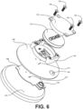
- FIG. 6 shows an example exploded view of a partially embedded active sensor 106. More specifically, FIG. 6 shows an apparatus comprising a sensor 106 positioned in an interior of a tire 103.
- the sensor 106 includes a power source housing 146, where at least a portion of the sensor 106 interlocks with a rubber portion 143 of a tire 103. In one embodiment, the portion of the sensor 106 that interlocks with the rubber 143 is the PCB 166.
- the power source housing 146 is disposed on an interior surface of the tire 103, where the power source housing 146 is fastened to the PCB 166 through the rubber 186. Electrical conductors are positioned between the power source housing 146 and the PCB 166, where the electrical conductors extend through the rubber 186.
- the PCB 166 is separated from the power source housing 146 by a top piece of green rubber 186.
- the base piece of green rubber 183 and the top piece of green rubber 186 cure together during vulcanization to secure the PCB 166 and electronic components 169 to the innerliner 133 of the tire 103.
- the PCB 166 is connected to the power source housing 146 through one or more connection holes 213 in the top piece of green rubber 186. While FIG. 6 depicts three connection holes 213, other embodiments will have more or fewer connection holes 213. According to one embodiment, the one or more connection holes 213 are large enough to fit the tip of a soldering iron.
- one or more electrical conductors extend between a terminal of a battery 176 and an electrical contact on the PCB 166.
- the electrical conductors of the power source housing 146 can be soldered to pads on the PCB 166 after the green rubber pieces 183, 186 are cured together.
- one or more connection holes 213 are sized to accommodate mechanical fasteners 156. The mechanical fasteners 156 secure the power source housing 146 to the PCB 166 through the connection holes 213 in the top piece of green rubber 186 or the rubber 143 after curing.
- the sensor 106 includes a cover 153 that is attached to the power source housing 146. When attached, the cover 153 forms a seal with the power source housing 146 to prevent water and debris from entering the power source housing 146 and interfering with the electrical connections disposed therein. In some embodiments, the cover 153 encloses the power source housing 146 such that no portion of the power source housing 146 is exposed.
- the sensing portal 149 extends through the rubber 143 such that at least a portion of the sensing portal 149 is exposed to the inner cavity 139 of the tire 103.
- the PCB 166 is directly connected to the power source housing 146.
- a flange 196 extends outwardly from the PCB 166.
- the flange 196 extends outwardly from the power source housing 146.
- the flange 196 consists of one or more extensions extending in at least one direction away from the power source housing 146.
- the PCB 166 and power source housing 146 are interlocked with one or more pieces of green rubber 183, 186 or with the resulting rubber 143 after curing.
- the power source housing 146 includes a thread 159 which corresponds to and opposes a thread 163 of the cover 153. While FIG. 8 shows the power source housing thread 159 on the exterior of the sidewalls 209 of the power source housing 146, other embodiments include the thread 159 on the interior of the power source housing sidewalls 209.
- a seal ring 216 is used to prevent water and debris from entering the battery receptacle.
- the seal ring 216 comprises a rubber o-ring 216. According to other embodiments, other shapes and types of seal rings 216 are used.
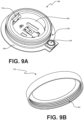
- FIG. 9A and 9B depict one embodiment of a power source housing 146 and a corresponding cover 153.
- FIG. 9A shows a power source housing 146 including a flange 196 and a thread 159 on the exterior of the sidewalls 209.
- the power source housing thread 159 corresponds to the thread 163 on the cover 153 shown in FIG. 9B .
- FIG. 10 an example of a cross-section of an embodiment is shown depicting one method of interlocking a portion of the sensor 106 with rubber by way of an amount of rubber disposed in at least one channel 219 extending through at least a portion of the sensor 106.
- the sensor 106 interlocks with the rubber 143 by way of an amount of rubber disposed in one or more channels 219 extending through at least a portion of the sensor 106.
- FIG. 10 shows the channels 219 entering the exterior of the sidewalls 209 of the power source housing 146, turning, and extending down through the power source housing floor 206 and through the PCB 166.
- the channels 219 extend only partially through the sidewalls 209.
- the channels 219 extend partially or wholly through the flange 196.
- the rubber flows into the channels 219 and then hardens. Once vulcanization is completed, the cured rubber 143 inside the channels 219 holds the sensor 106 in position in the tire 103.
- disjunctive language such as the phrase "at least one of X, Y, or Z," unless specifically stated otherwise, is otherwise understood with the context as used in general to present that an item, term, etc., may be either X, Y, or Z, or any combination thereof (e.g., X, Y, and/or Z).
- disjunctive language is not generally intended to, and should not, imply that certain embodiments require at least one of X, at least one of Y, or at least one of Z to each be present.
Landscapes
- Engineering & Computer Science (AREA)
- Mechanical Engineering (AREA)
- Measuring Fluid Pressure (AREA)
- Tires In General (AREA)
Abstract
Description
- In the manufacture of a pneumatic tire, the tire is typically built on the drum of a tire-building machine, which is known in the art as a tire building drum. Numerous tire components are wrapped about and/or applied to the drum in sequence, forming a cylindrical-shaped tire carcass. The tire carcass is then expanded into a toroidal shape for receipt of the remaining components of the tire, such as a belt package and a rubber tread. The completed toroidally-shaped unvulcanized tire carcass, typically called a green tire, is then inserted into a mold or press for forming of the tread pattern and curing or vulcanization.
- The invention relates to a tire-sensor-system in accordance with claim 1, to an apparatus in accordance with claim 6 and to a method in accordance with claim 12.
- Dependent claims refer to preferred embodiments of the invention.
- While the invention is mainly described in the context of a pneumatic tire below, it is to be understood that the invention may also be employed in a non-pneumatic tire without affecting the overall concept or operation of the invention.
- Many aspects of the present disclosure can be better understood with reference to the following drawings. The components in the drawings are not necessarily to scale, with emphasis instead being placed upon clearly illustrating the principles of the disclosure. Moreover, in the drawings, like reference numerals designate corresponding parts throughout the several views.
-
FIG. 1 is a drawing of a vehicle with one or more tires that include a partially embedded active sensor according to various embodiments of the present disclosure. -
FIG. 2 is a perspective cross-sectional view of a tire shown inFIG. 1 , after installation of an active sensor according to various embodiments of the present disclosure. -
FIG. 3 is an example of a partially embedded active sensor ofFIG. 2 according to various embodiments of the present disclosure. -
FIG. 4 is an example of an exploded view of a partially embedded active sensor ofFIG. 3 according to various embodiments of the present disclosure. -
FIG. 5A is an example perspective view of a printed circuit board according to various embodiments of the present disclosure. -
FIG. 5B is an example perspective view of a power source housing according to various embodiments of the present disclosure. -
FIG. 6 is an example of an exploded view of a partially embedded active sensor ofFIG. 2 according to various embodiments of the present disclosure. -
FIG. 7 is an example of a partially embedded active sensor ofFIG. 2 according to various embodiments of the present disclosure. -
FIG. 8 is an example assembly view of a partially embedded active sensor ofFIG. 2 according to various embodiments of the present disclosure. -
FIG. 9A is a perspective view of a power source housing according to various embodiments of the present disclosure. -
FIG. 9B is a perspective view of a removable cover corresponding to the power source housing ofFIG. 9A according to various embodiments of the present disclosure. -
FIG. 10 is an example cross-sectional perspective view of the assembly shown inFIG. 2 according to various embodiments of the present disclosure. - "Axial" and "axially" mean lines or directions that are parallel to the axis of rotation of the tire.
- "Axially inward" and "axially inwardly" refer to an axial direction that is toward the axial center of the tire.
- "Axially outward" and "axially outwardly" refer to an axial direction that is away from the axial center of the tire.
- "Circumferential" means lines or directions extending along the perimeter of the surface of the annular tread perpendicular to the axial direction.
- "Equatorial plane (EP)" means the plane perpendicular to the tire's axis of rotation and passing through the center of its tread.
- "Inboard side" means the side of the tire nearest the vehicle when the tire is mounted on a wheel and the wheel is mounted on the vehicle.
- "Innerliner" means the layer or layers of elastomer or other material that form the inside surface of a tubeless tire and that contain the inflating fluid within the tire.
- "Lateral" means an axial direction.
- "Lateral edges" means a line tangent to the axially outermost tread contact patch or footprint as measured under normal load and tire inflation, the lines being parallel to the equatorial centerplane.
- "Outboard side" means the side of the tire farthest away from the vehicle when the tire is mounted on a wheel and the wheel is mounted on the vehicle.
- "Radial" and "radially" mean lines or directions that are perpendicular to the axis of rotation of the tire.
- "Radially inward" and "radially inwardly" refer to a radial direction that is toward the central axis of rotation of the tire.
- "Radially outward" and "radially outwardly" refer to a radial direction that is away from the central axis of rotation of the tire.
- "TPMS" means a tire pressure monitoring system, which is an electronic system that measures the internal pressure of a tire and is capable of communicating the pressure to a processor that is mounted on the vehicle and/or is in electronic communication with electronic systems of the vehicle.
- With reference to
FIG. 1 , avehicle 100 is shown with one ormore tires 103. Eachtire 103 includes a partially embeddedsensor 106. In some embodiments, thesensor 106 is a component of a tire pressure monitoring system (TPMS). According to various embodiments, each one of thetires 103 on thevehicle 100 may include one or more of the embeddedsensors 106. While thevehicle 100 is depicted as a commercial truck, thevehicle 100 may comprise any type of vehicle that employs tires where the commercial truck is presented as an example. To this end, thevehicle 100 may comprise other vehicles falling into various categories such as passenger vehicles, off-road vehicles and the like, in which such vehicles include a greater or lesser number oftires 103 than are shown inFIG. 1 . - Turning to
FIG. 2 , shown is a cross-sectional view of thetire 103 according to various embodiments. Thetire 103 includes a pair ofbead areas 109, each one of which is formed with abead core 113 that is embedded in therespective bead area 109. Each one of a pair ofsidewalls 116 extends radially outwardly from arespective bead area 109 to a ground-contactingtread 119. Thetread 119 is formed with multiple tread elements ortread blocks 123 and defines a radiallyouter surface 126. Thetire 103 is reinforced by acarcass 129 that toroidally extends from onebead area 109 to theother bead area 109. Aninnerliner 133 is formed on the inner or inside surface of thecarcass 129. Thetire 103 is mounted on the flange of a wheel or rim 136 (FIG. 1 ) forming aninternal cavity 139. - According to one embodiment, a
sensor 106 is mounted to thetire 103. Thesensor 106 detects certain real-time parameters of thetire 103, and preferably includes a pressure sensor to sense the inflation pressure within acavity 139 of thetire 103, and a temperature sensor to sense the temperature of thetire 103 and/or the temperature in thecavity 139 of thetire 103. In some embodiments, thesensor 106 may be a commercially available tire pressure monitoring system (TPMS) module or other sensing unit. - Turning to
FIG. 3 , thesensor 106 is at least partially embedded in theinnerliner 133 of thetire 103 where various portions of thesensor 106 interlock with therubber 143. In one embodiment, thesensor 106 may include apower source housing 146 and asensing portal 149 to sense the inflation pressure within acavity 139 of thetire 103 and the temperature of thecavity 139 or structure of thetire 103.FIG. 3 shows an assembled apparatus, comprising asensor 106 interlocked withrubber 143, thesensor 106 including apower source housing 146. At least a portion of thepower source housing 146 protrudes through therubber 143. - The
power source housing 146 includes aremovable cover 153 which seals to thepower source housing 146 to prevent water and debris from interfering with the electrical components and connections disposed therein. In some embodiments, theremovable cover 153 can serve as an antenna which transmits data from thesensor 106 to thevehicle 100 or another recipient. In some embodiments, thepower source housing 146 includes aremovable cover 153, theremovable cover 153 attaching to thepower source housing 146 via one ormore fasteners 156. Examples offasteners 156 include, but are not limited to, screws, nuts, bolts, studs, pins, clamps, or other fasteners. In other embodiments, thecover 153 may be hingedly attached to thepower source housing 146 and secured by means of a latch, pin, clasp, or other means to secure thecover 153 in place. In further embodiments, as illustrated inFIGS. 9A, and 9B , the apparatus further comprises a first thread 159 (FIG. 9A ) on thesensor 106, and a second thread 163 (FIG. 9B ) on a side of theremovable cover 153. Thefirst thread 159 opposes thesecond thread 163. In some embodiments, thefirst thread 159 is disposed on thepower source housing 146. - In
FIG. 4 , an example exploded view of the partially embeddedsensor 106 is shown. Thepower source housing 146 is connected to a flexible printed circuit board orPCB 166 which includeselectronic components 169 such as processors, resistors, transistors, capacitors, inductors, diodes, or other components of the sensing circuitry. Thepower source housing 146 includes a pair ofelectrodes 173 which extend up through thepower source housing 146 from theelectronic components 169 on thePCB 166 to make contact with the positive and negative terminals of abattery 176. In one embodiment, thepower source housing 146 also includes abattery holder 179 to secure thebattery 176 in thepower source housing 146. According to one embodiment, thebattery 176 is a coin cell battery. However, any other type of battery could be used as well. As shown inFIG. 4 , thesensing portal 149 may be connected to thePCB 166 outside thepower source housing 146 to provide direct access to thecavity 139 of atire 103 to sense the pressure of thetire 103. - In one embodiment, the
sensor 106 is assembled by connecting thePCB 166 having theelectronic components 169 to thepower source housing 146. ThePCB 166 andpower source housing 146 are secured between pieces ofrubber sensor 106 is secured between a base piece ofgreen rubber 183 and a top piece ofgreen rubber 186. The top piece ofgreen rubber 186 includes anopening 189 to accommodate thepower source housing 146. The top piece ofgreen rubber 186 or another piece ofgreen rubber 193 includes anopening 194 to accommodate thesensing portal 149. In some embodiments, thesensor 106 interlocks with therubber 143 by way of one ormore flanges 196 extending from a portion of thesensor 106. - According to various embodiments, the
sensor 106 is secured in therubber 143 by interlocking theflange 196 of thesensor 106 with the pieces ofrubber power source housing 146 includes theflange 196. In an alternative embodiment, theflange 196 is an extension of thePCB 166. Theflange 196 is shown inFIG. 4 as rectangular in shape. However, in various embodiments theflange 196 is circular, triangular, hexagonal, or any other shape which extends at least in part beyond the outer edges of thepower source housing 146 so as to interlock with therubber 143. Additionally, in some embodiments, theflange 196 may include holes, cutouts, pins, bosses, or other features to increase the cured strength of therubber pieces flange 196. Furthermore, theflange 196 inFIG. 4 is shown extending outwardly from thepower source housing 146 in all directions on a plane. However, in other embodiments, theflange 196 extends outwardly in at least one direction from thepower source housing 146. - Once the
PCB 166,power source housing 146, and pieces ofgreen rubber innerliner 133 of a green tire. The green tire is then cured, and the pieces ofrubber sensor 106 in thetire 103 such that thesensor 106 is interlocked with the curedrubber 143. At least a portion of thepower source housing 146 protrudes through the curedrubber 143 such that it is exposed to thecavity 139. The portion protruding through therubber 143 includes abattery receptacle 199. According to various embodiments, a method for assembling thesensor 106 in thetire 103 comprises the steps of providing asensor 106 comprising apower source housing 146 attached to a printedcircuit board 166; interlocking a portion of thesensor 106 withgreen rubber power source housing 146 is exposed in an axially inward direction of the green tire; and curing the green tire after interlocking thesensor 106 with thegreen rubber - After the
tire 103 has been cured, thesensor 106 is ready to receive thebattery 176. The assembly is completed by placing abattery 176 into the exposedportion 199 of thepower source housing 146 and attaching aremoveable cover 153 to thepower source housing 146. Thus, thesensor 106 is exposed to the heat of the curing process, thereby interlocking thesensor 106 with the curedrubber 143. However, thebattery 176 is put into place after the curing process given that the battery would not likely survive the heat of the curing process itself. - Turning to
FIG. 5A and 5B , shown is one embodiment of thesensor 106.FIG. 5A depicts an example of aflexible PCB 166 with variouselectronic components 169. The specificelectronic components 169 that may be included on thePCB 166 will vary depending on the number and type of sensor circuits that are desired. In one embodiment, an antenna is disposed on a surface of thesensor 106. An antennafeed line channel 203 is shown on thePCB 166. The antennafeed line channel 203 extends up from thePCB 166 through thepower source housing 146.. In some embodiments, there are additional structural covers around theelectronic components 169 andPCB 166 to prevent theelectronic components 169 from coming into contact with the rubber during vulcanization. -
FIG. 5B shows an example of apower source housing 146. The power source housing includes afloor 206 and a plurality ofsidewalls 209 extending substantially perpendicularly from thefloor 206. Together, the plurality ofsidewalls 209 and thefloor 206 create thebattery receptacle 199. Thepower source housing 146 also includes abattery holder 179 andelectrodes 173. In some embodiments, thepower source housing 146 comprises a heat-resistant polymer. Thepower source housing 146 is secured to thePCB 166. In some embodiments, thepower source housing 146 may be injection molded to thePCB 166. -
FIG. 6 shows an example exploded view of a partially embeddedactive sensor 106. More specifically,FIG. 6 shows an apparatus comprising asensor 106 positioned in an interior of atire 103. Thesensor 106 includes apower source housing 146, where at least a portion of thesensor 106 interlocks with arubber portion 143 of atire 103. In one embodiment, the portion of thesensor 106 that interlocks with therubber 143 is thePCB 166. Thepower source housing 146 is disposed on an interior surface of thetire 103, where thepower source housing 146 is fastened to thePCB 166 through therubber 186. Electrical conductors are positioned between thepower source housing 146 and thePCB 166, where the electrical conductors extend through therubber 186. - In this embodiment, the
PCB 166 is separated from thepower source housing 146 by a top piece ofgreen rubber 186. The base piece ofgreen rubber 183 and the top piece ofgreen rubber 186 cure together during vulcanization to secure thePCB 166 andelectronic components 169 to theinnerliner 133 of thetire 103. ThePCB 166 is connected to thepower source housing 146 through one or more connection holes 213 in the top piece ofgreen rubber 186. WhileFIG. 6 depicts threeconnection holes 213, other embodiments will have more or fewer connection holes 213. According to one embodiment, the one or more connection holes 213 are large enough to fit the tip of a soldering iron. In this embodiment, one or more electrical conductors extend between a terminal of abattery 176 and an electrical contact on thePCB 166. The electrical conductors of thepower source housing 146 can be soldered to pads on thePCB 166 after thegreen rubber pieces mechanical fasteners 156. Themechanical fasteners 156 secure thepower source housing 146 to thePCB 166 through the connection holes 213 in the top piece ofgreen rubber 186 or therubber 143 after curing. - In
FIG. 7 , shown is an example of asensor 106 that is at least partially embedded in theinnerliner 133 of thetire 103. Various portions of thesensor 106 interlock with therubber 143. In one embodiment, thesensor 106 includes acover 153 that is attached to thepower source housing 146. When attached, thecover 153 forms a seal with thepower source housing 146 to prevent water and debris from entering thepower source housing 146 and interfering with the electrical connections disposed therein. In some embodiments, thecover 153 encloses thepower source housing 146 such that no portion of thepower source housing 146 is exposed. Thesensing portal 149 extends through therubber 143 such that at least a portion of thesensing portal 149 is exposed to theinner cavity 139 of thetire 103. - Turning to
FIG. 8 , thePCB 166 is directly connected to thepower source housing 146. In some embodiments, aflange 196 extends outwardly from thePCB 166. In other embodiments, theflange 196 extends outwardly from thepower source housing 146. In further embodiments, theflange 196 consists of one or more extensions extending in at least one direction away from thepower source housing 146. ThePCB 166 andpower source housing 146 are interlocked with one or more pieces ofgreen rubber rubber 143 after curing. In some embodiments, thepower source housing 146 includes athread 159 which corresponds to and opposes athread 163 of thecover 153. WhileFIG. 8 shows the powersource housing thread 159 on the exterior of thesidewalls 209 of thepower source housing 146, other embodiments include thethread 159 on the interior of the powersource housing sidewalls 209. - When the
sensor 106 is interlocked with the curedrubber 143 by virtue of theflange 196 mentioned above, thebattery 176 is inserted into thebattery receptacle 199 of thepower source housing 146 and thecover 153 is attached. In some embodiments, aseal ring 216 is used to prevent water and debris from entering the battery receptacle. InFIG. 8 , theseal ring 216 comprises a rubber o-ring 216. According to other embodiments, other shapes and types of seal rings 216 are used. -
FIG. 9A and 9B depict one embodiment of apower source housing 146 and acorresponding cover 153.FIG. 9A shows apower source housing 146 including aflange 196 and athread 159 on the exterior of thesidewalls 209. The powersource housing thread 159 corresponds to thethread 163 on thecover 153 shown inFIG. 9B . - In
FIG. 10 , an example of a cross-section of an embodiment is shown depicting one method of interlocking a portion of thesensor 106 with rubber by way of an amount of rubber disposed in at least onechannel 219 extending through at least a portion of thesensor 106. In this embodiment, thesensor 106 interlocks with therubber 143 by way of an amount of rubber disposed in one ormore channels 219 extending through at least a portion of thesensor 106.FIG. 10 shows thechannels 219 entering the exterior of thesidewalls 209 of thepower source housing 146, turning, and extending down through the powersource housing floor 206 and through thePCB 166. However, in other embodiments, thechannels 219 extend only partially through thesidewalls 209. In further embodiments, thechannels 219 extend partially or wholly through theflange 196. When the pieces ofgreen rubber channels 219 and then hardens. Once vulcanization is completed, the curedrubber 143 inside thechannels 219 holds thesensor 106 in position in thetire 103. - In the present disclosure, disjunctive language such as the phrase "at least one of X, Y, or Z," unless specifically stated otherwise, is otherwise understood with the context as used in general to present that an item, term, etc., may be either X, Y, or Z, or any combination thereof (e.g., X, Y, and/or Z). Thus, such disjunctive language is not generally intended to, and should not, imply that certain embodiments require at least one of X, at least one of Y, or at least one of Z to each be present.
Claims (15)
- A tire-sensor-system, the system comprising:a sensor (106) positioned in an interior of a tire (103), the sensor including a power source housing (146), wherein at least a portion of the sensor (106) interlocks with a rubber portion (143) of a tire (103), wherein the power source housing (146) is disposed on an interior surface of the tire and wherein the power source housing (146) is fastened to the portion of the sensor (106) through the rubber portion;and at least one electrical conductor between the power source housing (146) and the portion of the sensor (106), the at least one electrical conductor extending through the rubber portion.
- The system of claim 1, wherein the sensor (106) is a component of a tire pressure monitoring system and/or wherein the portion of the sensor is a printed circuit board (166).
- The system of claim 1 or 2, wherein the at least one electrical conductor extends between a terminal of a battery (176) and an electrical contact on the portion of the sensor (106).
- The system of at least one of the previous claims, wherein the power source housing (146) includes a removable cover (153), the removable cover (153) attaching to the power source housing (146) via a fastener (156).
- The system of at least one of the previous claims, further comprising an antenna disposed on a surface of the sensor (106).
- An apparatus comprising a sensor (106) interlocked in rubber, the sensor (106) including a power source housing (146), wherein at least a portion of the power source housing (146) protrudes through the rubber (143).
- The apparatus of claim 6, wherein the rubber (143) comprises green rubber and/or wherein the sensor (106) interlocks with the rubber (143) by way of an amount of rubber disposed in at least one channel (219) extending through at least a portion of the sensor (106).
- The apparatus of at least one of the claims 6 or 7, wherein the sensor (106) interlocks with the rubber (143) by way of at least one flange (196) extending from at least a portion of the sensor (106).
- The apparatus of at least one of the claims 6 to 8, wherein the power source housing (146) includes a removable cover (153).
- The apparatus of at least one of the claims 6 to 9, further comprising a first thread (159) on the sensor (106); and a second thread (163) on a side of the removable cover (153), the first thread opposing the second thread.
- The apparatus of at least one of the claims 6 to 10, wherein the removable cover (153) is fastened to the power source housing (146) by a fastener (156) and/or further comprising an antenna disposed on a surface of the sensor (106).
- A method comprising:providing a sensor (106) comprising a power source housing (146) attached to a printed circuit board (166);interlocking a portion of the sensor (106) with green rubber within a green tire such that at least a portion of the power source housing (146) is exposed in an axially inward direction of the green tire; andcuring the green tire after the interlocking of the portion of the sensor (106) with the green rubber.
- The method of claim 12, further comprising interlocking a portion of the sensor (106) with green rubber by way of an amount of rubber disposed in at least one channel (219) extending through at least a portion of the sensor (106) and/or further comprising interlocking at least one flange (196) of the portion of the sensor (106) with the green rubber.
- The method of claim 12 or 13, further comprising placing a battery (176) into the portion of the power source housing (146).
- The method of claim 12, 13 or 14, further comprising attaching a removeable cover (153) to the power source housing (146) and/or further comprising positioning an antenna on a surface of the sensor (106).
Applications Claiming Priority (2)
| Application Number | Priority Date | Filing Date | Title |
|---|---|---|---|
| US202263383725P | 2022-11-15 | 2022-11-15 | |
| US18/498,173 US20240157736A1 (en) | 2022-11-15 | 2023-10-31 | Inclusion of a sensor in a tire |
Publications (2)
| Publication Number | Publication Date |
|---|---|
| EP4371789A1 true EP4371789A1 (en) | 2024-05-22 |
| EP4371789B1 EP4371789B1 (en) | 2025-10-01 |
Family
ID=88837194
Family Applications (1)
| Application Number | Title | Priority Date | Filing Date |
|---|---|---|---|
| EP23209940.8A Active EP4371789B1 (en) | 2022-11-15 | 2023-11-14 | Inclusion of a sensor in a tire |
Country Status (2)
| Country | Link |
|---|---|
| US (1) | US20240157736A1 (en) |
| EP (1) | EP4371789B1 (en) |
Families Citing this family (1)
| Publication number | Priority date | Publication date | Assignee | Title |
|---|---|---|---|---|
| IT202200005120A1 (en) * | 2022-03-16 | 2023-09-16 | Trelleborg Wheel Sys Italia Spa | FASTENER OF ELECTRONIC DEVICES ON TIRES AND METHOD OF MANUFACTURE OF A TIRE EQUIPPED WITH SUCH FASTENER |
Citations (6)
| Publication number | Priority date | Publication date | Assignee | Title |
|---|---|---|---|---|
| US5749984A (en) * | 1995-12-29 | 1998-05-12 | Michelin Recherche Et Technique S.A. | Tire monitoring system and method |
| CH708955A2 (en) * | 2013-12-03 | 2015-06-15 | Rolf Liener | Apparatus for dynamic, remote measurement of tread depth, gas pressure, temperature, age, and brand signature of a vehicle tire. |
| US20210039451A1 (en) * | 2018-03-19 | 2021-02-11 | Nokian Renkaat Oyj | Tire with a module |
| US20210114419A1 (en) * | 2018-06-29 | 2021-04-22 | Tyrata, Inc. | Structures and methods providing tread sensor integration |
| WO2021162464A1 (en) * | 2020-02-10 | 2021-08-19 | 유성원 | Tire wear detection device |
| EP4015255A1 (en) * | 2020-12-15 | 2022-06-22 | The Goodyear Tire & Rubber Company | Tire with polymer plug for tread wear sensing and method of manufacturing |
Family Cites Families (4)
| Publication number | Priority date | Publication date | Assignee | Title |
|---|---|---|---|---|
| US3787806A (en) * | 1972-06-26 | 1974-01-22 | Avco Corp | Tire pressure warning apparatus |
| DE60225851T2 (en) * | 2002-06-28 | 2009-04-09 | Pirelli Tyre S.P.A. | DEVICE FOR MONITORING CHARACTERIZING PARAMETERS OF A TIRE |
| US12344051B2 (en) * | 2019-10-31 | 2025-07-01 | Cerebrum Sensor Technologies, Inc. | Sensor assemblies and systems for monitoring a dynamic object |
| US11420487B2 (en) * | 2020-06-01 | 2022-08-23 | Revvo Technologies, Inc. | Method and apparatus for mounting a tire sensor |
-
2023
- 2023-10-31 US US18/498,173 patent/US20240157736A1/en active Pending
- 2023-11-14 EP EP23209940.8A patent/EP4371789B1/en active Active
Patent Citations (6)
| Publication number | Priority date | Publication date | Assignee | Title |
|---|---|---|---|---|
| US5749984A (en) * | 1995-12-29 | 1998-05-12 | Michelin Recherche Et Technique S.A. | Tire monitoring system and method |
| CH708955A2 (en) * | 2013-12-03 | 2015-06-15 | Rolf Liener | Apparatus for dynamic, remote measurement of tread depth, gas pressure, temperature, age, and brand signature of a vehicle tire. |
| US20210039451A1 (en) * | 2018-03-19 | 2021-02-11 | Nokian Renkaat Oyj | Tire with a module |
| US20210114419A1 (en) * | 2018-06-29 | 2021-04-22 | Tyrata, Inc. | Structures and methods providing tread sensor integration |
| WO2021162464A1 (en) * | 2020-02-10 | 2021-08-19 | 유성원 | Tire wear detection device |
| EP4015255A1 (en) * | 2020-12-15 | 2022-06-22 | The Goodyear Tire & Rubber Company | Tire with polymer plug for tread wear sensing and method of manufacturing |
Also Published As
| Publication number | Publication date |
|---|---|
| US20240157736A1 (en) | 2024-05-16 |
| EP4371789B1 (en) | 2025-10-01 |
Similar Documents
| Publication | Publication Date | Title |
|---|---|---|
| US11260705B2 (en) | Flexible tire sensor unit | |
| JP7666917B2 (en) | Embedded and encapsulated tire sensor unit | |
| US6581657B1 (en) | Disposition of transponder coupling elements in tires | |
| EP4371789B1 (en) | Inclusion of a sensor in a tire | |
| US20240343073A1 (en) | Tire with polymer plug for tread wear sensing | |
| US10953710B2 (en) | Tire with printed strain sensors | |
| US20060123899A1 (en) | Pneumatic tire having accommodation tool of electronic component | |
| US20250367985A1 (en) | Antenna connection for integrated rfid tag and tpms sensor | |
| EP1547826B1 (en) | Apparatus and method for incorporating an annular antenna and electronics into a tire | |
| US20230182512A1 (en) | Tire with cellular member and sensor | |
| US20260061784A1 (en) | Systems and methods for integrating sensors into rim flange transition area of a tire during process of manufacture | |
| US11628695B2 (en) | Tire sensor container system for improved sensor functionality and longevity | |
| US7736454B2 (en) | Method for incorporating an annular antenna and electronics into a tire | |
| US20260116128A1 (en) | Inclusion of a sensor base in a tire | |
| US12420597B2 (en) | Tire, retreaded tire, and retreaded tire production method | |
| KR20240159919A (en) | Fixing element for fixing electronic device to tire and method for manufacturing tire provided with said fixing element | |
| EP2343182A1 (en) | Tire molding drum | |
| US20240418607A1 (en) | Detection of uneven and irregular treadwear | |
| JP2006234578A (en) | Attaching member, pneumatic tire, and manufacturing method for pneumatic tire | |
| CN121928913A (en) | Incorporating sensor substrates in tires | |
| CN116262402A (en) | Tire with honeycomb member and sensor | |
| US11938762B2 (en) | Tire sensor attachment structure | |
| US20250153517A1 (en) | Systems and methods for including sensors on wheels | |
| EP0492784A2 (en) | Pneumatic tyre and method for manufacturing the same |
Legal Events
| Date | Code | Title | Description |
|---|---|---|---|
| PUAI | Public reference made under article 153(3) epc to a published international application that has entered the european phase |
Free format text: ORIGINAL CODE: 0009012 |
|
| STAA | Information on the status of an ep patent application or granted ep patent |
Free format text: STATUS: THE APPLICATION HAS BEEN PUBLISHED |
|
| AK | Designated contracting states |
Kind code of ref document: A1 Designated state(s): AL AT BE BG CH CY CZ DE DK EE ES FI FR GB GR HR HU IE IS IT LI LT LU LV MC ME MK MT NL NO PL PT RO RS SE SI SK SM TR |
|
| STAA | Information on the status of an ep patent application or granted ep patent |
Free format text: STATUS: REQUEST FOR EXAMINATION WAS MADE |
|
| 17P | Request for examination filed |
Effective date: 20241021 |
|
| RBV | Designated contracting states (corrected) |
Designated state(s): AL AT BE BG CH CY CZ DE DK EE ES FI FR GB GR HR HU IE IS IT LI LT LU LV MC ME MK MT NL NO PL PT RO RS SE SI SK SM TR |
|
| GRAP | Despatch of communication of intention to grant a patent |
Free format text: ORIGINAL CODE: EPIDOSNIGR1 |
|
| STAA | Information on the status of an ep patent application or granted ep patent |
Free format text: STATUS: GRANT OF PATENT IS INTENDED |
|
| RIC1 | Information provided on ipc code assigned before grant |
Ipc: B60C 19/00 20060101ALN20250403BHEP Ipc: B29D 30/00 20060101ALN20250403BHEP Ipc: B60C 23/20 20060101ALI20250403BHEP Ipc: B60C 23/04 20060101ALI20250403BHEP Ipc: B60C 11/24 20060101AFI20250403BHEP |
|
| INTG | Intention to grant announced |
Effective date: 20250424 |
|
| GRAS | Grant fee paid |
Free format text: ORIGINAL CODE: EPIDOSNIGR3 |
|
| GRAA | (expected) grant |
Free format text: ORIGINAL CODE: 0009210 |
|
| STAA | Information on the status of an ep patent application or granted ep patent |
Free format text: STATUS: THE PATENT HAS BEEN GRANTED |
|
| AK | Designated contracting states |
Kind code of ref document: B1 Designated state(s): AL AT BE BG CH CY CZ DE DK EE ES FI FR GB GR HR HU IE IS IT LI LT LU LV MC ME MK MT NL NO PL PT RO RS SE SI SK SM TR |
|
| REG | Reference to a national code |
Ref country code: GB Ref legal event code: FG4D Ref country code: CH Ref legal event code: F10 Free format text: ST27 STATUS EVENT CODE: U-0-0-F10-F00 (AS PROVIDED BY THE NATIONAL OFFICE) Effective date: 20251001 |
|
| REG | Reference to a national code |
Ref country code: IE Ref legal event code: FG4D |
|
| REG | Reference to a national code |
Ref country code: DE Ref legal event code: R096 Ref document number: 602023007133 Country of ref document: DE |
|
| PGFP | Annual fee paid to national office [announced via postgrant information from national office to epo] |
Ref country code: DE Payment date: 20251022 Year of fee payment: 3 |
|
| PGFP | Annual fee paid to national office [announced via postgrant information from national office to epo] |
Ref country code: AT Payment date: 20260113 Year of fee payment: 3 |
|
| PGFP | Annual fee paid to national office [announced via postgrant information from national office to epo] |
Ref country code: FR Payment date: 20251119 Year of fee payment: 3 |
|
| REG | Reference to a national code |
Ref country code: NL Ref legal event code: MP Effective date: 20251001 |
|
| REG | Reference to a national code |
Ref country code: AT Ref legal event code: MK05 Ref document number: 1842180 Country of ref document: AT Kind code of ref document: T Effective date: 20251001 |
|
| PG25 | Lapsed in a contracting state [announced via postgrant information from national office to epo] |
Ref country code: NL Free format text: LAPSE BECAUSE OF FAILURE TO SUBMIT A TRANSLATION OF THE DESCRIPTION OR TO PAY THE FEE WITHIN THE PRESCRIBED TIME-LIMIT Effective date: 20251001 |
|
| PG25 | Lapsed in a contracting state [announced via postgrant information from national office to epo] |
Ref country code: ES Free format text: LAPSE BECAUSE OF FAILURE TO SUBMIT A TRANSLATION OF THE DESCRIPTION OR TO PAY THE FEE WITHIN THE PRESCRIBED TIME-LIMIT Effective date: 20251001 |
|
| REG | Reference to a national code |
Ref country code: LT Ref legal event code: MG9D |
|
| PG25 | Lapsed in a contracting state [announced via postgrant information from national office to epo] |
Ref country code: NO Free format text: LAPSE BECAUSE OF FAILURE TO SUBMIT A TRANSLATION OF THE DESCRIPTION OR TO PAY THE FEE WITHIN THE PRESCRIBED TIME-LIMIT Effective date: 20260101 |
|
| PG25 | Lapsed in a contracting state [announced via postgrant information from national office to epo] |
Ref country code: AT Free format text: LAPSE BECAUSE OF FAILURE TO SUBMIT A TRANSLATION OF THE DESCRIPTION OR TO PAY THE FEE WITHIN THE PRESCRIBED TIME-LIMIT Effective date: 20251001 Ref country code: FI Free format text: LAPSE BECAUSE OF FAILURE TO SUBMIT A TRANSLATION OF THE DESCRIPTION OR TO PAY THE FEE WITHIN THE PRESCRIBED TIME-LIMIT Effective date: 20251001 Ref country code: HR Free format text: LAPSE BECAUSE OF FAILURE TO SUBMIT A TRANSLATION OF THE DESCRIPTION OR TO PAY THE FEE WITHIN THE PRESCRIBED TIME-LIMIT Effective date: 20251001 |
|
| PGFP | Annual fee paid to national office [announced via postgrant information from national office to epo] |
Ref country code: IT Payment date: 20251130 Year of fee payment: 3 |
|
| PG25 | Lapsed in a contracting state [announced via postgrant information from national office to epo] |
Ref country code: RS Free format text: LAPSE BECAUSE OF FAILURE TO SUBMIT A TRANSLATION OF THE DESCRIPTION OR TO PAY THE FEE WITHIN THE PRESCRIBED TIME-LIMIT Effective date: 20260101 |
|
| PG25 | Lapsed in a contracting state [announced via postgrant information from national office to epo] |
Ref country code: IS Free format text: LAPSE BECAUSE OF FAILURE TO SUBMIT A TRANSLATION OF THE DESCRIPTION OR TO PAY THE FEE WITHIN THE PRESCRIBED TIME-LIMIT Effective date: 20260201 |
|
| PG25 | Lapsed in a contracting state [announced via postgrant information from national office to epo] |
Ref country code: PT Free format text: LAPSE BECAUSE OF FAILURE TO SUBMIT A TRANSLATION OF THE DESCRIPTION OR TO PAY THE FEE WITHIN THE PRESCRIBED TIME-LIMIT Effective date: 20260202 Ref country code: CZ Free format text: LAPSE BECAUSE OF FAILURE TO SUBMIT A TRANSLATION OF THE DESCRIPTION OR TO PAY THE FEE WITHIN THE PRESCRIBED TIME-LIMIT Effective date: 20251001 |
|
| PG25 | Lapsed in a contracting state [announced via postgrant information from national office to epo] |
Ref country code: PL Free format text: LAPSE BECAUSE OF FAILURE TO SUBMIT A TRANSLATION OF THE DESCRIPTION OR TO PAY THE FEE WITHIN THE PRESCRIBED TIME-LIMIT Effective date: 20251001 |
|
| PG25 | Lapsed in a contracting state [announced via postgrant information from national office to epo] |
Ref country code: LV Free format text: LAPSE BECAUSE OF FAILURE TO SUBMIT A TRANSLATION OF THE DESCRIPTION OR TO PAY THE FEE WITHIN THE PRESCRIBED TIME-LIMIT Effective date: 20251001 |
|
| PG25 | Lapsed in a contracting state [announced via postgrant information from national office to epo] |
Ref country code: BG Free format text: LAPSE BECAUSE OF FAILURE TO SUBMIT A TRANSLATION OF THE DESCRIPTION OR TO PAY THE FEE WITHIN THE PRESCRIBED TIME-LIMIT Effective date: 20251001 |
|
| PG25 | Lapsed in a contracting state [announced via postgrant information from national office to epo] |
Ref country code: RO Free format text: LAPSE BECAUSE OF FAILURE TO SUBMIT A TRANSLATION OF THE DESCRIPTION OR TO PAY THE FEE WITHIN THE PRESCRIBED TIME-LIMIT Effective date: 20251001 |
|
| PG25 | Lapsed in a contracting state [announced via postgrant information from national office to epo] |
Ref country code: LT Free format text: LAPSE BECAUSE OF FAILURE TO SUBMIT A TRANSLATION OF THE DESCRIPTION OR TO PAY THE FEE WITHIN THE PRESCRIBED TIME-LIMIT Effective date: 20251001 |
|
| PG25 | Lapsed in a contracting state [announced via postgrant information from national office to epo] |
Ref country code: MC Free format text: LAPSE BECAUSE OF FAILURE TO SUBMIT A TRANSLATION OF THE DESCRIPTION OR TO PAY THE FEE WITHIN THE PRESCRIBED TIME-LIMIT Effective date: 20251001 |
|
| REG | Reference to a national code |
Ref country code: DE Ref legal event code: R097 Ref document number: 602023007133 Country of ref document: DE |
|
| PG25 | Lapsed in a contracting state [announced via postgrant information from national office to epo] |
Ref country code: SM Free format text: LAPSE BECAUSE OF FAILURE TO SUBMIT A TRANSLATION OF THE DESCRIPTION OR TO PAY THE FEE WITHIN THE PRESCRIBED TIME-LIMIT Effective date: 20251001 |
|
| PG25 | Lapsed in a contracting state [announced via postgrant information from national office to epo] |
Ref country code: DK Free format text: LAPSE BECAUSE OF FAILURE TO SUBMIT A TRANSLATION OF THE DESCRIPTION OR TO PAY THE FEE WITHIN THE PRESCRIBED TIME-LIMIT Effective date: 20251001 |
|
| PG25 | Lapsed in a contracting state [announced via postgrant information from national office to epo] |
Ref country code: LU Free format text: LAPSE BECAUSE OF NON-PAYMENT OF DUE FEES Effective date: 20251114 |
|
| PG25 | Lapsed in a contracting state [announced via postgrant information from national office to epo] |
Ref country code: EE Free format text: LAPSE BECAUSE OF FAILURE TO SUBMIT A TRANSLATION OF THE DESCRIPTION OR TO PAY THE FEE WITHIN THE PRESCRIBED TIME-LIMIT Effective date: 20251001 |
|
| PG25 | Lapsed in a contracting state [announced via postgrant information from national office to epo] |
Ref country code: SK Free format text: LAPSE BECAUSE OF FAILURE TO SUBMIT A TRANSLATION OF THE DESCRIPTION OR TO PAY THE FEE WITHIN THE PRESCRIBED TIME-LIMIT Effective date: 20251001 |
|
| PG25 | Lapsed in a contracting state [announced via postgrant information from national office to epo] |
Ref country code: SE Free format text: LAPSE BECAUSE OF FAILURE TO SUBMIT A TRANSLATION OF THE DESCRIPTION OR TO PAY THE FEE WITHIN THE PRESCRIBED TIME-LIMIT Effective date: 20251001 |
|
| PLBE | No opposition filed within time limit |
Free format text: ORIGINAL CODE: 0009261 |
|
| STAA | Information on the status of an ep patent application or granted ep patent |
Free format text: STATUS: NO OPPOSITION FILED WITHIN TIME LIMIT |
|
| REG | Reference to a national code |
Ref country code: CH Ref legal event code: L10 Free format text: ST27 STATUS EVENT CODE: U-0-0-L10-L00 (AS PROVIDED BY THE NATIONAL OFFICE) Effective date: 20260812 |