EP4015255A1 - Tire with polymer plug for tread wear sensing and method of manufacturing - Google Patents
Tire with polymer plug for tread wear sensing and method of manufacturing Download PDFInfo
- Publication number
- EP4015255A1 EP4015255A1 EP21211359.1A EP21211359A EP4015255A1 EP 4015255 A1 EP4015255 A1 EP 4015255A1 EP 21211359 A EP21211359 A EP 21211359A EP 4015255 A1 EP4015255 A1 EP 4015255A1
- Authority
- EP
- European Patent Office
- Prior art keywords
- tire
- tread
- wire
- polymer plug
- chamber
- Prior art date
- Legal status (The legal status is an assumption and is not a legal conclusion. Google has not performed a legal analysis and makes no representation as to the accuracy of the status listed.)
- Pending
Links
Images


Classifications
-
- B—PERFORMING OPERATIONS; TRANSPORTING
- B60—VEHICLES IN GENERAL
- B60C—VEHICLE TYRES; TYRE INFLATION; TYRE CHANGING; CONNECTING VALVES TO INFLATABLE ELASTIC BODIES IN GENERAL; DEVICES OR ARRANGEMENTS RELATED TO TYRES
- B60C11/00—Tyre tread bands; Tread patterns; Anti-skid inserts
- B60C11/24—Wear-indicating arrangements
- B60C11/243—Tread wear sensors, e.g. electronic sensors
-
- B—PERFORMING OPERATIONS; TRANSPORTING
- B29—WORKING OF PLASTICS; WORKING OF SUBSTANCES IN A PLASTIC STATE IN GENERAL
- B29D—PRODUCING PARTICULAR ARTICLES FROM PLASTICS OR FROM SUBSTANCES IN A PLASTIC STATE
- B29D30/00—Producing pneumatic or solid tyres or parts thereof
- B29D30/0061—Accessories, details or auxiliary operations not otherwise provided for
-
- B—PERFORMING OPERATIONS; TRANSPORTING
- B60—VEHICLES IN GENERAL
- B60C—VEHICLE TYRES; TYRE INFLATION; TYRE CHANGING; CONNECTING VALVES TO INFLATABLE ELASTIC BODIES IN GENERAL; DEVICES OR ARRANGEMENTS RELATED TO TYRES
- B60C11/00—Tyre tread bands; Tread patterns; Anti-skid inserts
- B60C11/24—Wear-indicating arrangements
- B60C11/246—Tread wear monitoring systems
-
- B—PERFORMING OPERATIONS; TRANSPORTING
- B60—VEHICLES IN GENERAL
- B60C—VEHICLE TYRES; TYRE INFLATION; TYRE CHANGING; CONNECTING VALVES TO INFLATABLE ELASTIC BODIES IN GENERAL; DEVICES OR ARRANGEMENTS RELATED TO TYRES
- B60C23/00—Devices for measuring, signalling, controlling, or distributing tyre pressure or temperature, specially adapted for mounting on vehicles; Arrangement of tyre inflating devices on vehicles, e.g. of pumps or of tanks; Tyre cooling arrangements
- B60C23/02—Signalling devices actuated by tyre pressure
- B60C23/04—Signalling devices actuated by tyre pressure mounted on the wheel or tyre
- B60C23/0491—Constructional details of means for attaching the control device
- B60C23/0493—Constructional details of means for attaching the control device for attachment on the tyre
-
- B—PERFORMING OPERATIONS; TRANSPORTING
- B29—WORKING OF PLASTICS; WORKING OF SUBSTANCES IN A PLASTIC STATE IN GENERAL
- B29D—PRODUCING PARTICULAR ARTICLES FROM PLASTICS OR FROM SUBSTANCES IN A PLASTIC STATE
- B29D30/00—Producing pneumatic or solid tyres or parts thereof
- B29D30/0061—Accessories, details or auxiliary operations not otherwise provided for
- B29D2030/0083—Attaching monitoring devices to tyres before or after vulcanization by inserting them inside tyre cavities
Definitions
- the invention relates to vehicle tires. More particularly, the invention relates to vehicle tires with sensors that determine various conditions within the tires. Specifically, the invention is directed to a tire with a tread including a polymer plug that provides a direct wear sensor system for the tire, and to methods of manufacturing.
- the tire In the manufacture of a pneumatic tire, the tire is typically built on the drum of a tire-building machine, which is known in the art as a tire building drum. Numerous tire components are wrapped about and/or applied to the drum in sequence, forming a cylindrical-shaped tire carcass. The tire carcass is then expanded into a toroidal shape for receipt of the remaining components of the tire, such as a belt package and a rubber tread. The completed toroidally-shaped unvulcanized tire carcass, which is known in the art at that stage as a green tire, is then inserted into a mold or press for forming of the tread pattern and curing or vulcanization.
- the data can be communicated to electronic systems of the vehicle, such as vehicle stability and/or braking systems, in order to provide improved control of the vehicle and to monitor or track driving behavior.
- electronic systems of the vehicle such as vehicle stability and/or braking systems
- Mechanical tread wear indicators are not able to provide such data to electronic systems of the vehicle.
- prior art electronic wear sensors were developed. Such sensors are known in the art as direct wear sensors, as they attempt to directly measure tire wear, rather than providing an estimate from indirect means.
- prior art direct wear sensors include resistance-based electronic sensors that typically are incorporated into tread elements of tires. As the tread element wears, resistors in the sensor also wear, leading to a change in the electrical resistance of the sensor. By measuring the resistance of the sensor and transmitting the measured resistance data to a processor, wear of the tread can be determined.
- a direct wear sensor system for a vehicle tire that includes a structure which is easy to install in the tire, withstands the operating environment of the tire, accurately indicates tire wear in a repeatable manner, and is capable of transmitting a wear indication to an electronic control system of the vehicle.
- a tire with a polymer plug for tread wear sensing includes a pair of sidewalls, each one of which extends radially outwardly from a respective bead area to a ground-contacting tread.
- the tread is formed with a plurality of tread elements and a radially outer surface.
- a chamber is formed in a selected one of the tread elements.
- a sensor unit is mounted to the tire and includes a pair of electrical contacts.
- the polymer plug includes a wire disposed in the chamber. The wire includes proximal ends and a distal end near a radially outer surface of the tread. A liquid polymer is injected into the chamber and cured.
- An electrical circuit is formed by each proximal end of the wire electrically contacting a respective one of the sensor unit electrical contacts.
- Axial and “axially” mean lines or directions that are parallel to the axis of rotation of the tire.
- CAN bus is an abbreviation for controller area network.
- “Circumferential” means lines or directions extending along the perimeter of the surface of the annular tread perpendicular to the axial direction.
- “Footprint” means the contact patch or area of contact created by the tire tread with a flat surface, such as the ground, as the tire rotates or rolls.
- TPMS means a tire pressure monitoring system, which is an electronic system that measures the internal pressure of a tire and is capable of communicating the pressure to a processor that is mounted on the vehicle and/or is in electronic communication with electronic systems of the vehicle.
- Thread element or “traction element” means a rib or a block element defined by a shape having adjacent grooves.
- FIG. 1 An exemplary embodiment of the tire 12 with a polymer plug for tread wear sensing of the present invention is presented in Figures 1 through 9 .
- the tire 12 with a polymer plug 10 provides a system for indicating the wear on one or more tires supporting a vehicle 14. While the vehicle 14 is depicted as a commercial truck, the invention is not to be so restricted. The principles of the invention find application in other vehicle categories, such as passenger vehicles, off-the-road vehicles and the like, in which vehicles may be supported by more or fewer tires than shown in Figure 1 .
- the tire 12 includes a pair of bead areas 16, each one of which is formed with a bead core 18 that is embedded in the respective bead areas.
- Each one of a pair of sidewalls 20 extends radially outwardly from a respective bead area 16 to a ground-contacting tread 22.
- the tread 22 is formed with multiple tread elements or tread blocks 32 and includes a radially outer surface 34.
- the tire 12 is reinforced by a carcass 24 that toroidally extends from one bead area 16 to the other bead area, as known to those skilled in the art.
- An innerliner 26 is formed on the inner or inside surface of the carcass 24.
- the tire 12 is mounted on the flange of a wheel or rim 36 ( Figure 1 ) as known in the art, forming an internal cavity 30.
- a sensor unit 28 preferably is mounted to the tire 12.
- the sensor unit 28 detects certain real-time parameters of the tire 12, and preferably includes a pressure sensor to sense the inflation pressure within a cavity 30 of the tire, and a temperature sensor to sense the temperature of the tire and/or the temperature in the cavity.
- the sensor unit 28 may be a commercially available tire pressure monitoring system (TPMS) module or sensing unit.
- TPMS tire pressure monitoring system
- the sensor unit 28 preferably also includes a processor and memory to store tire identification (ID) information for each specific tire 12.
- the tire ID may include manufacturing information for the tire 12, including: the tire model; size information, such as rim size, width, and outer diameter; manufacturing location; manufacturing date; a treadcap code that includes or correlates to a compound identification; and a mold code that includes or correlates to a tread structure identification.
- the tire ID may also include a service history or other information to identify specific features and parameters of each tire 12.
- the sensor unit 28 preferably further includes an antenna for wirelessly transmitting 40 ( Figure 9 ) measured parameters and tire ID data to a remote processor for analysis, such as a processor integrated into a vehicle electronic control unit and/or CAN bus.
- a remote processor for analysis such as a processor integrated into a vehicle electronic control unit and/or CAN bus.
- a chamber 42 is formed in a selected tread element 32, preferably before the container 38 and the sensor unit 28 are attached to the tire 12.
- the chamber 42 extends from the internal cavity 30 into the selected tread element 32, but not completely through the selected tread element to the tread surface 34.
- the chamber 42 may be formed using different techniques. For example, when the tire 12 is a green or uncured tire, an object such as a nail may be inserted into the green tire from the direction of the cavity 30 and into the selected tread element 32.
- the object includes a length that provides a corresponding radial length 44 for the chamber 42. The length 44 ends at a set distance 46 below the tread outer surface 34.
- the object also includes a diameter that provides a corresponding diameter 48 for the chamber 42.
- the diameter 48 of the chamber 42 ensures that a wire 60, to be described below, may be inserted into the chamber.
- the tire is cured.
- the object is removed, which creates the chamber 42.
- the object includes a surface coating, such as a low-friction coating, which enables easy removal of the nail after the tire has been cured.
- the chamber 42 may be formed by drilling from the direction of the cavity 30 and into the selected tread element 32.
- the chamber includes the radial length 44 and the diameter 48.
- other techniques that are known to those skilled in the art may be employed to form the chamber 42 in a cured or uncured tire 12.
- the tire with a polymer plug 10 includes a conductive wire 60.
- the wire 60 preferably is an insulated wire, but may be an uninsulated wire, depending on particular design considerations.
- the wire is formed in a U-shape and thus has proximal ends 62 and a distal end 64.
- the proximal ends 62 of the wire 60 contact the electrical contacts 54 of the sensor unit 28, as will be described in greater detail below.
- the proximal ends 62 of the wire 60 may be attached to a printed circuit board 56 through a conductive attachment 58.
- the printed circuit board 56 provides a stable connection point for the proximal ends 62 of the wire 60.
- the printed circuit board 56 is formed with an opening 66, which enables the distal end 64 of the wire 60 to be inserted through the circuit board.
- the distal end 64 of the wire 60 is inserted into the chamber 42 from the tire cavity 30, and the printed circuit board 56 provides a positive mechanical stop for the wire in the chamber.
- the length 44 and diameter 48 of the chamber 42 allow the wire 60 to be received and seat in the chamber, with the distal end 64 of the wire near the tread surface 34.
- the distal end 64 of the wire 60 is a set distance 70 below the tread surface 34.
- a liquid polymer 68 is injected through the printed circuit board opening 66 an into the chamber.
- the liquid polymer 68 is then cured to solidify it.
- the container 38 is attached to the tire 12. More particularly, the container 38 includes a base 74 that is attached to the innerliner 26 with an adhesive. The container base 74 is formed with an opening 76, which enables the proximal ends 62 of the wire 60 to pass into the container 38.
- the sensor unit 28 is installed by inserted it into the container 38, which receives and secures the sensor unit. The sensor unit 28 is rotated to enable each sensor electrical contact 54 ( Figure 3 ) to contact a respective proximal end 62 of the wire 60.
- a continuous electrical circuit is formed by the wire 60 and the contact of each proximal wire end 62 with each respective electrical contact 54 of the sensor unit 28.
- the distal end 64 of the wire 60 is disposed at a predetermined distance 70 ( Figure 6 ) below the radially outer surface 34 of the tread 22, which corresponds to a minimum recommended tread depth.
- the cured liquid polymer 68 also wears.
- the distal end 64 of the wire 60 breaks, creating a break in the electrical circuit formed by the wire and the contact of each proximal wire end 62 with each respective sensor unit electrical contact 54.
- the sensor unit 28 senses the break in the electrical circuit, and wirelessly transmits 40 a notice 86 that the electrical circuit has broken and/or that the minimum recommended tread depth has been reached.
- the notice 86 transmitted 40 by the sensor unit 28 may be sent to a remote processor, such as a processor that is integrated into a vehicle electronic control unit, CAN bus, and/or a cloud-based server.
- a remote processor such as a processor that is integrated into a vehicle electronic control unit, CAN bus, and/or a cloud-based server.
- the notice 86 by communicating that the minimum tread depth has been reached, thus indicates when replacement or retreading of the tire 12 should take place.
- the structure of the above-described tire with a polymer plug 10 may be altered or rearranged, or components or steps known to those skilled in the art omitted or added, without affecting the overall concept or operation of the invention.
- a single polymer plug may be disposed in the tread 22 of the tire 12, or multiple polymer plugs may be disposed in the tread about the tire.
- the tread wear plug 44 may include multiple wires 60, each one having a distal end 64 spaced apart from the other wires, which enables the tread wear plug to indicate different wear states of the tread 22, without affecting the overall concept or operation of the invention.
Landscapes
- Engineering & Computer Science (AREA)
- Mechanical Engineering (AREA)
- Tires In General (AREA)
Abstract
Description
- The invention relates to vehicle tires. More particularly, the invention relates to vehicle tires with sensors that determine various conditions within the tires. Specifically, the invention is directed to a tire with a tread including a polymer plug that provides a direct wear sensor system for the tire, and to methods of manufacturing.
- In the manufacture of a pneumatic tire, the tire is typically built on the drum of a tire-building machine, which is known in the art as a tire building drum. Numerous tire components are wrapped about and/or applied to the drum in sequence, forming a cylindrical-shaped tire carcass. The tire carcass is then expanded into a toroidal shape for receipt of the remaining components of the tire, such as a belt package and a rubber tread. The completed toroidally-shaped unvulcanized tire carcass, which is known in the art at that stage as a green tire, is then inserted into a mold or press for forming of the tread pattern and curing or vulcanization.
- The use of tread wear indicators that are formed on a tire tread before or after curing is known in the art. For example, prior art mechanical tread wear indicators include color indicia disposed below certain tread elements, tie bars disposed in the tread grooves, or characters formed in the tread elements, all of which provide a visual indicator of wear. Such mechanical indicators may be difficult for a vehicle operator to see, and thus do not easily provide information to the operator.
- In addition, it is often desirable to collect electronic data for the wear state of the tire. The data can be communicated to electronic systems of the vehicle, such as vehicle stability and/or braking systems, in order to provide improved control of the vehicle and to monitor or track driving behavior. Mechanical tread wear indicators are not able to provide such data to electronic systems of the vehicle.
- To provide an indication of tire wear to vehicle electronic systems, prior art indirect wear estimation techniques were developed. Such techniques involve estimation of tire wear through certain tire and vehicle parameters, rather than direct measurement of wear. For example, tire pressure, tire temperature, vehicle speed, vehicle mileage, vehicle acceleration and other parameters may be employed to estimate tire wear. Such indirect estimation of tire wear can be difficult to perform accurately, and typically involves complex modeling techniques.
- In order to provide a wear indication to vehicle electronic systems based on a direct measurement of tire wear, prior art electronic wear sensors were developed. Such sensors are known in the art as direct wear sensors, as they attempt to directly measure tire wear, rather than providing an estimate from indirect means. By way of example, prior art direct wear sensors include resistance-based electronic sensors that typically are incorporated into tread elements of tires. As the tread element wears, resistors in the sensor also wear, leading to a change in the electrical resistance of the sensor. By measuring the resistance of the sensor and transmitting the measured resistance data to a processor, wear of the tread can be determined.
- While prior art direct wear sensors are acceptable for their intended purpose, many such sensors are difficult to install in the tire. Other direct wear sensors cannot withstand the harsh operating environment of the tire for a prolonged period, such as the recommended life of the tire. Still other direct wear sensors are not capable of maintaining precise and repeatable indication of tire wear over the recommended life of the tire.
- As a result, it is desirable to develop a direct wear sensor system for a vehicle tire that includes a structure which is easy to install in the tire, withstands the operating environment of the tire, accurately indicates tire wear in a repeatable manner, and is capable of transmitting a wear indication to an electronic control system of the vehicle.
- The invention relates to a tire in accordance with claim 1 and to methods of manufacturing in accordance with
claims - Dependent claims refer to preferred embodiments of the invention.
- According to an aspect of an exemplary embodiment of the invention, a tire with a polymer plug for tread wear sensing is provided. The tire includes a pair of sidewalls, each one of which extends radially outwardly from a respective bead area to a ground-contacting tread. The tread is formed with a plurality of tread elements and a radially outer surface. A chamber is formed in a selected one of the tread elements. A sensor unit is mounted to the tire and includes a pair of electrical contacts. The polymer plug includes a wire disposed in the chamber. The wire includes proximal ends and a distal end near a radially outer surface of the tread. A liquid polymer is injected into the chamber and cured. An electrical circuit is formed by each proximal end of the wire electrically contacting a respective one of the sensor unit electrical contacts. When the selected one of the tread elements wears down to the distal end of the wire, the distal end of the wire breaks, which breaks the electrical circuit. A notice is transmitted by the sensor unit when the electrical circuit has broken.
- "Axial" and "axially" mean lines or directions that are parallel to the axis of rotation of the tire.
- "Axially inward" and "axially inwardly" refer to an axial direction that is toward the axial center of the tire.
- "Axially outward" and "axially outwardly" refer to an axial direction that is away from the axial center of the tire.
- "CAN bus" is an abbreviation for controller area network.
- "Circumferential" means lines or directions extending along the perimeter of the surface of the annular tread perpendicular to the axial direction.
- "Equatorial plane (EP)" means the plane perpendicular to the tire's axis of rotation and passing through the center of its tread.
- "Footprint" means the contact patch or area of contact created by the tire tread with a flat surface, such as the ground, as the tire rotates or rolls.
- "Lateral" means an axial direction.
- "Radial" and "radially" mean lines or directions that are perpendicular to the axis of rotation of the tire.
- "Radially inward" and "radially inwardly" refer to a radial direction that is toward the central axis of rotation of the tire.
- "Radially outward" and "radially outwardly" refer to a radial direction that is away from the central axis of rotation of the tire.
- "TPMS" means a tire pressure monitoring system, which is an electronic system that measures the internal pressure of a tire and is capable of communicating the pressure to a processor that is mounted on the vehicle and/or is in electronic communication with electronic systems of the vehicle.
- "Tread element" or "traction element" means a rib or a block element defined by a shape having adjacent grooves.
- The invention will be described by way of example and with reference to the accompanying drawings, in which:
-
Figure 1 is a schematic side view of a vehicle with tires that include an exemplary embodiment of the tire with polymer plug for tread wear sensing of the present invention; -
Figure 2 is a perspective cross-sectional view of a tire shown inFigure 1 , prior to installation of the polymer plug; -
Figure 3 is a perspective view of a TPMS sensor employed in the exemplary embodiment of the tire with polymer plug for tread wear sensing of the present invention; -
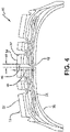
Figure 4 is a cross-sectional view of a portion of a tire with a chamber formed for the polymer plug for tread wear sensing of the present invention; -
Figure 5 is a schematic representation of a wire employed in the exemplary embodiment of the tire with polymer plug for tread wear sensing of the present invention; -
Figure 6 is a cross-sectional view of a portion of a tire with the wire shown inFigure 5 installed in the chamber shown inFigure 4 , with the radial orientation of the tire being reversed fromFigure 4 ; -
Figure 7 is a cross-sectional view of a portion of a tire during forming of the polymer plug for tread wear sensing of the present invention, with the radial orientation of the tire being the same asFigure 6 ; -
Figure 8 is a cross-sectional view of a portion of an exemplary embodiment of the tire with polymer plug for tread wear sensing of the present invention, showing the tire in an unworn state; and -
Figure 9 is a cross-sectional perspective view of the tire with polymer plug shown inFigure 8 , showing the tire in a worn state. - Similar numerals refer to similar parts throughout the drawings.
- An exemplary embodiment of the
tire 12 with a polymer plug for tread wear sensing of the present invention is presented inFigures 1 through 9 . With particular reference toFigure 1 , thetire 12 with apolymer plug 10 provides a system for indicating the wear on one or more tires supporting avehicle 14. While thevehicle 14 is depicted as a commercial truck, the invention is not to be so restricted. The principles of the invention find application in other vehicle categories, such as passenger vehicles, off-the-road vehicles and the like, in which vehicles may be supported by more or fewer tires than shown inFigure 1 . - Turning to
Figure 2 , thetire 12 includes a pair ofbead areas 16, each one of which is formed with abead core 18 that is embedded in the respective bead areas. Each one of a pair ofsidewalls 20 extends radially outwardly from arespective bead area 16 to a ground-contactingtread 22. Thetread 22 is formed with multiple tread elements or tread blocks 32 and includes a radiallyouter surface 34. Thetire 12 is reinforced by acarcass 24 that toroidally extends from onebead area 16 to the other bead area, as known to those skilled in the art. Aninnerliner 26 is formed on the inner or inside surface of thecarcass 24. Thetire 12 is mounted on the flange of a wheel or rim 36 (Figure 1 ) as known in the art, forming aninternal cavity 30. - A
sensor unit 28 preferably is mounted to thetire 12. Thesensor unit 28 detects certain real-time parameters of thetire 12, and preferably includes a pressure sensor to sense the inflation pressure within acavity 30 of the tire, and a temperature sensor to sense the temperature of the tire and/or the temperature in the cavity. Thesensor unit 28 may be a commercially available tire pressure monitoring system (TPMS) module or sensing unit. - The
sensor unit 28 preferably also includes a processor and memory to store tire identification (ID) information for eachspecific tire 12. For example, the tire ID may include manufacturing information for thetire 12, including: the tire model; size information, such as rim size, width, and outer diameter; manufacturing location; manufacturing date; a treadcap code that includes or correlates to a compound identification; and a mold code that includes or correlates to a tread structure identification. The tire ID may also include a service history or other information to identify specific features and parameters of eachtire 12. - The
sensor unit 28 preferably further includes an antenna for wirelessly transmitting 40 (Figure 9 ) measured parameters and tire ID data to a remote processor for analysis, such as a processor integrated into a vehicle electronic control unit and/or CAN bus. - The
sensor unit 28 may be mounted to thetire 12 using acontainer 38, which receives the sensor unit and is attached to theinnerliner 26 by an adhesive. Preferably, thecontainer 38 is flexible and is formed of an elastomer or polymer. Thecontainer 38 may be attached to thetire 12 before or after curing of the tire, and thesensor unit 28 preferably is inserted into the container after curing of the tire. As shown inFigure 3 , thesensor unit 28 preferably includes arigid housing 50 formed with abase 52. A pair ofelectrical contacts 54 are mounted on thebase 52 and extend through thehousing 50. - Turning to
Figure 4 , achamber 42 is formed in a selectedtread element 32, preferably before thecontainer 38 and thesensor unit 28 are attached to thetire 12. Thechamber 42 extends from theinternal cavity 30 into the selectedtread element 32, but not completely through the selected tread element to thetread surface 34. - To form the
chamber 42, different techniques may be employed. For example, when thetire 12 is a green or uncured tire, an object such as a nail may be inserted into the green tire from the direction of thecavity 30 and into the selectedtread element 32. The object includes a length that provides acorresponding radial length 44 for thechamber 42. Thelength 44 ends at aset distance 46 below the treadouter surface 34. The object also includes a diameter that provides acorresponding diameter 48 for thechamber 42. Thediameter 48 of thechamber 42 ensures that awire 60, to be described below, may be inserted into the chamber. Once the object is inserted into thetire 12, the tire is cured. After thetire 12 has been cured, the object is removed, which creates thechamber 42. Preferably, the object includes a surface coating, such as a low-friction coating, which enables easy removal of the nail after the tire has been cured. - When the
tire 12 is a cured tire, thechamber 42 may be formed by drilling from the direction of thecavity 30 and into the selectedtread element 32. When thechamber 42 is formed by drilling, the chamber includes theradial length 44 and thediameter 48. Of course, other techniques that are known to those skilled in the art may be employed to form thechamber 42 in a cured oruncured tire 12. - With reference to
Figures 5 and 6 , the tire with apolymer plug 10 includes aconductive wire 60. Thewire 60 preferably is an insulated wire, but may be an uninsulated wire, depending on particular design considerations. The wire is formed in a U-shape and thus has proximal ends 62 and adistal end 64. The proximal ends 62 of thewire 60 contact theelectrical contacts 54 of thesensor unit 28, as will be described in greater detail below. Optionally, the proximal ends 62 of thewire 60 may be attached to a printedcircuit board 56 through aconductive attachment 58. The printedcircuit board 56 provides a stable connection point for the proximal ends 62 of thewire 60. The printedcircuit board 56 is formed with anopening 66, which enables thedistal end 64 of thewire 60 to be inserted through the circuit board. - The
distal end 64 of thewire 60 is inserted into thechamber 42 from thetire cavity 30, and the printedcircuit board 56 provides a positive mechanical stop for the wire in the chamber. Thelength 44 anddiameter 48 of thechamber 42 allow thewire 60 to be received and seat in the chamber, with thedistal end 64 of the wire near thetread surface 34. Preferably, thedistal end 64 of thewire 60 is aset distance 70 below thetread surface 34. - Referring to
Figure 7 , once thewire 60 is seated in thechamber 42, aliquid polymer 68 is injected through the printed circuit board opening 66 an into the chamber. Theliquid polymer 68 is then cured to solidify it. - Turning to
Figure 8 , after theliquid polymer 68 has been cured, thecontainer 38 is attached to thetire 12. More particularly, thecontainer 38 includes a base 74 that is attached to theinnerliner 26 with an adhesive. Thecontainer base 74 is formed with anopening 76, which enables the proximal ends 62 of thewire 60 to pass into thecontainer 38. Thesensor unit 28 is installed by inserted it into thecontainer 38, which receives and secures the sensor unit. Thesensor unit 28 is rotated to enable each sensor electrical contact 54 (Figure 3 ) to contact a respectiveproximal end 62 of thewire 60. - Turning to
Figures 8 and9 , operation of the tire with apolymer plug 10 is shown. With particular reference toFigure 8 , a continuous electrical circuit is formed by thewire 60 and the contact of eachproximal wire end 62 with each respectiveelectrical contact 54 of thesensor unit 28. Thedistal end 64 of thewire 60 is disposed at a predetermined distance 70 (Figure 6 ) below the radiallyouter surface 34 of thetread 22, which corresponds to a minimum recommended tread depth. - Referring to
Figure 9 , as thetread 22 wears, the curedliquid polymer 68 also wears. When thetread 22 and the curedliquid polymer 68 wear down to thewire 60, thedistal end 64 of thewire 60 breaks, creating a break in the electrical circuit formed by the wire and the contact of eachproximal wire end 62 with each respective sensor unitelectrical contact 54. Thesensor unit 28 senses the break in the electrical circuit, and wirelessly transmits 40 anotice 86 that the electrical circuit has broken and/or that the minimum recommended tread depth has been reached. - The
notice 86 transmitted 40 by thesensor unit 28 may be sent to a remote processor, such as a processor that is integrated into a vehicle electronic control unit, CAN bus, and/or a cloud-based server. Thenotice 86, by communicating that the minimum tread depth has been reached, thus indicates when replacement or retreading of thetire 12 should take place. - In this manner, the tire with a
polymer plug 10 for tread wear sensing of the present invention indicates tire wear with components that are mounted within thetire 12, and does not require sensors that are external to the tire. The tire with apolymer plug 10 provides a direct wear sensor system for avehicle tire 12 that includes a structure which is easy to install in the tire, withstands the operating environment of the tire, accurately indicates tire wear in a repeatable manner, and is capable of transmitting a wear indication to an electronic control system of thevehicle 14. - The present invention also includes a method of determining wear of a tire using a polymer plug, and a method of forming a tire with a polymer plug for indicating tread depth. Each method includes steps in accordance with the description that is presented above and shown in
Figures 1 through 9 . - It is to be understood that the structure of the above-described tire with a
polymer plug 10 may be altered or rearranged, or components or steps known to those skilled in the art omitted or added, without affecting the overall concept or operation of the invention. For example, a single polymer plug may be disposed in thetread 22 of thetire 12, or multiple polymer plugs may be disposed in the tread about the tire. In addition, thetread wear plug 44 may includemultiple wires 60, each one having adistal end 64 spaced apart from the other wires, which enables the tread wear plug to indicate different wear states of thetread 22, without affecting the overall concept or operation of the invention.
Claims (14)
- A tire with a polymer plug for tread wear sensing,wherein the tire (12) comprises a pair of sidewalls (20), each one of which extends radially outwardly from a respective bead area (16) to a tread (22),wherein the tread (22) is formed with a plurality of tread elements (32) and a radially outer surface (34),wherein a chamber (42) is formed in a selected one of the tread elements (32), wherein a sensor unit (28) is mounted to the tire (12), the sensor unit (28) including a pair of electrical contacts (54),wherein the polymer plug (10) includes a wire (60) being disposed in the chamber (42), the wire (60) including proximal ends (62) and a distal end (64) near the radially outer surface (34) of the tread (22),wherein cured polymer is provided in the chamber (42), andwherein an electrical circuit (56) is formed by each proximal end (62) of the wire (60) electrically contacting a respective one of the sensor unit electrical contacts (54), whereby when the selected one of the tread elements (32) wears down to the distal end (64) of the wire (60), the distal end (64) of the wire breaks, thereby breaking the electrical circuit (56).
- The tire with a polymer plug of claim 1, configured such that a notice (86) can be transmitted by the sensor unit (28) when the electrical circuit (56) has broken.
- The tire with a polymer plug of at least one of the previous claims, wherein the distal end (64) of the wire (60) is disposed at a set distance (70) below the radially outer surface (34) of the tread (22), the set distance (70) preferably corresponding to a minimum recommended tread depth.
- The tire with a polymer plug of at least one of the previous claims, wherein the chamber (42) does not extend through the selected tread element (32) to the tread surface (34).
- The tire with a polymer plug of at least one of the previous claims, wherein the proximal ends (62) of the wire (60) are attached to a printed circuit board (56), and, optionally wherein the printed circuit board (56) is formed with an opening (66) and the distal end (64) of the wire (60) is inserted through the circuit board (56) into the chamber (42).
- The tire with a polymer plug of claim 5, wherein the printed circuit board (56) provides a positive mechanical stop for the wire (60) in the chamber (42).
- The tire with a polymer plug of at least one of the previous claims, wherein the sensor unit (28) is mounted to the tire (12) using a container (38).
- The tire with a polymer plug of claim 7, wherein the container (38) contains the sensor unit (28) and is attached to an innerliner (26) of the tire (12) by an adhesive.
- The tire with a polymer plug of claim 7 or 8, wherein the container (38) includes a base (52) with an opening, and wherein the proximal ends (62) of the wire (60) pass through the opening in the base (52).
- The tire with a polymer plug of at least one of the previous claims, wherein the sensor unit (28) includes an antenna for wirelessly transmitting a notice (86) to a remote processor, and, optionally, wherein the remote processor is integrated into at least one of a vehicle electronic control unit, a CAN bus, and a cloud-based server.
- The tire with a polymer plug of at least one of the previous claims, wherein the polymer plug (10) further comprises multiple wires, wherein each of said wires includes a distal end that is spaced apart from the other wires.
- A method of manufacturing a tire with a polymer plug (10) in accordance with at least one of the previous claims, the method comprising the step of injecting a liquid polymer (68) into the chamber (42) and curing the liquid polymer (68) thereby providing the cured polymer in the chamber (42).
- The method of claim 12 wherein the container (38) is attached to the tire (12) after the liquid polymer has been cured.
- A method of manufacturing a tire with a polymer plug (10) in accordance with at least one of the previous claims 1 to 11, the method comprising the step of forming the chamber (42) by (i) inserting an object into a selected one of the tread elements (32) from a direction of a tire cavity (30) prior to a curing of the tire (12), and removing the object after curing the tire (12), or by (ii) by drilling into a selected one of the tread elements (32) from a direction of a tire cavity (30).
Applications Claiming Priority (2)
| Application Number | Priority Date | Filing Date | Title |
|---|---|---|---|
| US202063125440P | 2020-12-15 | 2020-12-15 | |
| US17/502,076 US20220185030A1 (en) | 2020-12-15 | 2021-10-15 | Tire with polymer plug for tread wear sensing |
Publications (1)
| Publication Number | Publication Date |
|---|---|
| EP4015255A1 true EP4015255A1 (en) | 2022-06-22 |
Family
ID=78819923
Family Applications (1)
| Application Number | Title | Priority Date | Filing Date |
|---|---|---|---|
| EP21211359.1A Pending EP4015255A1 (en) | 2020-12-15 | 2021-11-30 | Tire with polymer plug for tread wear sensing and method of manufacturing |
Country Status (2)
| Country | Link |
|---|---|
| US (1) | US20220185030A1 (en) |
| EP (1) | EP4015255A1 (en) |
Cited By (2)
| Publication number | Priority date | Publication date | Assignee | Title |
|---|---|---|---|---|
| EP4197820A1 (en) * | 2021-12-14 | 2023-06-21 | The Goodyear Tire & Rubber Company | Integrated tread wear sensor and tpms container for a tire |
| EP4371789A1 (en) * | 2022-11-15 | 2024-05-22 | The Goodyear Tire & Rubber Company | Inclusion of a sensor in a tire |
Families Citing this family (1)
| Publication number | Priority date | Publication date | Assignee | Title |
|---|---|---|---|---|
| US11964515B2 (en) | 2020-12-15 | 2024-04-23 | The Goodyear Tire & Rubber Company | Integrated tread wear sensor and TPMS container for a tire |
Citations (5)
| Publication number | Priority date | Publication date | Assignee | Title |
|---|---|---|---|---|
| US20050061069A1 (en) * | 2002-01-31 | 2005-03-24 | Michel Robert | Method and systems for measuring the degree of wear on a tire |
| EP2810794A1 (en) * | 2013-06-07 | 2014-12-10 | The Goodyear Tire & Rubber Company | Vehicle tire and tread wear device assembly and method |
| WO2018047781A1 (en) * | 2016-09-07 | 2018-03-15 | 株式会社デンソー | Tire-mounted sensor |
| EP3611041A1 (en) * | 2018-08-13 | 2020-02-19 | Hankook Tire & Technology Co., Ltd | Tire sensor fixed in screwing manner and tire having the same |
| KR102124829B1 (en) * | 2020-02-10 | 2020-06-22 | 유성원 | Apparatus for monitoring wear of tire |
Family Cites Families (2)
| Publication number | Priority date | Publication date | Assignee | Title |
|---|---|---|---|---|
| DE19745734B4 (en) * | 1997-10-16 | 2007-07-05 | Bayerische Motoren Werke Ag | Abrasion sensor for detecting the tread depth of a tire of motor vehicles |
| EP3498499B1 (en) * | 2017-12-18 | 2019-12-18 | Nokian Renkaat Oyj | A tire with an insert configured to measure wear of a tread |
-
2021
- 2021-10-15 US US17/502,076 patent/US20220185030A1/en active Pending
- 2021-11-30 EP EP21211359.1A patent/EP4015255A1/en active Pending
Patent Citations (5)
| Publication number | Priority date | Publication date | Assignee | Title |
|---|---|---|---|---|
| US20050061069A1 (en) * | 2002-01-31 | 2005-03-24 | Michel Robert | Method and systems for measuring the degree of wear on a tire |
| EP2810794A1 (en) * | 2013-06-07 | 2014-12-10 | The Goodyear Tire & Rubber Company | Vehicle tire and tread wear device assembly and method |
| WO2018047781A1 (en) * | 2016-09-07 | 2018-03-15 | 株式会社デンソー | Tire-mounted sensor |
| EP3611041A1 (en) * | 2018-08-13 | 2020-02-19 | Hankook Tire & Technology Co., Ltd | Tire sensor fixed in screwing manner and tire having the same |
| KR102124829B1 (en) * | 2020-02-10 | 2020-06-22 | 유성원 | Apparatus for monitoring wear of tire |
Cited By (2)
| Publication number | Priority date | Publication date | Assignee | Title |
|---|---|---|---|---|
| EP4197820A1 (en) * | 2021-12-14 | 2023-06-21 | The Goodyear Tire & Rubber Company | Integrated tread wear sensor and tpms container for a tire |
| EP4371789A1 (en) * | 2022-11-15 | 2024-05-22 | The Goodyear Tire & Rubber Company | Inclusion of a sensor in a tire |
Also Published As
| Publication number | Publication date |
|---|---|
| US20220185030A1 (en) | 2022-06-16 |
Similar Documents
| Publication | Publication Date | Title |
|---|---|---|
| EP4015255A1 (en) | Tire with polymer plug for tread wear sensing and method of manufacturing | |
| KR100948846B1 (en) | Method And System For Monitoring A Tyre During The Running Of A Vehicle | |
| EP4015251B1 (en) | Tire with tread wear sensor plug | |
| US11090984B2 (en) | Sensor system for monitoring tire wear | |
| US10935466B2 (en) | Integrated tire sensor and reader system | |
| US10960714B2 (en) | Tire with printed shear sensors | |
| US20140166168A1 (en) | Autonomous, plug-in wear or abrasion sensing system | |
| EP4015252A1 (en) | Vehicle tire sensor retaining system | |
| US11498371B2 (en) | Tire data information system | |
| US10792960B2 (en) | Article with electronic component inclusion | |
| US11260705B2 (en) | Flexible tire sensor unit | |
| EP3628479B1 (en) | Tire with printed strain sensors | |
| US11964515B2 (en) | Integrated tread wear sensor and TPMS container for a tire | |
| JP4268363B2 (en) | Pneumatic tire and tire deformation detection method | |
| EP4197820A1 (en) | Integrated tread wear sensor and tpms container for a tire | |
| US20230182510A1 (en) | Systems and methods for tire tread wear sensing and electrostatic discharge | |
| EP4015256A1 (en) | Tire sensor container system | |
| EP4197823A1 (en) | Tire with cellular member and sensor | |
| CN115805778A (en) | Tire wear automatic monitoring device and system |
Legal Events
| Date | Code | Title | Description |
|---|---|---|---|
| PUAI | Public reference made under article 153(3) epc to a published international application that has entered the european phase |
Free format text: ORIGINAL CODE: 0009012 |
|
| STAA | Information on the status of an ep patent application or granted ep patent |
Free format text: STATUS: THE APPLICATION HAS BEEN PUBLISHED |
|
| AK | Designated contracting states |
Kind code of ref document: A1 Designated state(s): AL AT BE BG CH CY CZ DE DK EE ES FI FR GB GR HR HU IE IS IT LI LT LU LV MC MK MT NL NO PL PT RO RS SE SI SK SM TR |
|
| STAA | Information on the status of an ep patent application or granted ep patent |
Free format text: STATUS: REQUEST FOR EXAMINATION WAS MADE |
|
| 17P | Request for examination filed |
Effective date: 20221222 |
|
| RBV | Designated contracting states (corrected) |
Designated state(s): AL AT BE BG CH CY CZ DE DK EE ES FI FR GB GR HR HU IE IS IT LI LT LU LV MC MK MT NL NO PL PT RO RS SE SI SK SM TR |
|
| STAA | Information on the status of an ep patent application or granted ep patent |
Free format text: STATUS: EXAMINATION IS IN PROGRESS |
|
| 17Q | First examination report despatched |
Effective date: 20230811 |