EP4371746A2 - Systems and methods for robotic arm end effector for tailored through thickness reinforcement - Google Patents
Systems and methods for robotic arm end effector for tailored through thickness reinforcement Download PDFInfo
- Publication number
- EP4371746A2 EP4371746A2 EP23204626.8A EP23204626A EP4371746A2 EP 4371746 A2 EP4371746 A2 EP 4371746A2 EP 23204626 A EP23204626 A EP 23204626A EP 4371746 A2 EP4371746 A2 EP 4371746A2
- Authority
- EP
- European Patent Office
- Prior art keywords
- fibrous preform
- end effector
- needle
- presser foot
- moving
- Prior art date
- Legal status (The legal status is an assumption and is not a legal conclusion. Google has not performed a legal analysis and makes no representation as to the accuracy of the status listed.)
- Withdrawn
Links
Images





Classifications
-
- D—TEXTILES; PAPER
- D04—BRAIDING; LACE-MAKING; KNITTING; TRIMMINGS; NON-WOVEN FABRICS
- D04H—MAKING TEXTILE FABRICS, e.g. FROM FIBRES OR FILAMENTARY MATERIAL; FABRICS MADE BY SUCH PROCESSES OR APPARATUS, e.g. FELTS, NON-WOVEN FABRICS; COTTON-WOOL; WADDING ; NON-WOVEN FABRICS FROM STAPLE FIBRES, FILAMENTS OR YARNS, BONDED WITH AT LEAST ONE WEB-LIKE MATERIAL DURING THEIR CONSOLIDATION
- D04H18/00—Needling machines
- D04H18/02—Needling machines with needles
-
- B—PERFORMING OPERATIONS; TRANSPORTING
- B29—WORKING OF PLASTICS; WORKING OF SUBSTANCES IN A PLASTIC STATE IN GENERAL
- B29C—SHAPING OR JOINING OF PLASTICS; SHAPING OF MATERIAL IN A PLASTIC STATE, NOT OTHERWISE PROVIDED FOR; AFTER-TREATMENT OF THE SHAPED PRODUCTS, e.g. REPAIRING
- B29C70/00—Shaping composites, i.e. plastics material comprising reinforcements, fillers or preformed parts, e.g. inserts
- B29C70/04—Shaping composites, i.e. plastics material comprising reinforcements, fillers or preformed parts, e.g. inserts comprising reinforcements only, e.g. self-reinforcing plastics
- B29C70/28—Shaping operations therefor
- B29C70/30—Shaping by lay-up, i.e. applying fibres, tape or broadsheet on a mould, former or core; Shaping by spray-up, i.e. spraying of fibres on a mould, former or core
- B29C70/38—Automated lay-up, e.g. using robots, laying filaments according to predetermined patterns
-
- B—PERFORMING OPERATIONS; TRANSPORTING
- B25—HAND TOOLS; PORTABLE POWER-DRIVEN TOOLS; MANIPULATORS
- B25J—MANIPULATORS; CHAMBERS PROVIDED WITH MANIPULATION DEVICES
- B25J15/00—Gripping heads and other end effectors
- B25J15/0071—Gripping heads and other end effectors with needles engaging into objects to be gripped
-
- B—PERFORMING OPERATIONS; TRANSPORTING
- B29—WORKING OF PLASTICS; WORKING OF SUBSTANCES IN A PLASTIC STATE IN GENERAL
- B29C—SHAPING OR JOINING OF PLASTICS; SHAPING OF MATERIAL IN A PLASTIC STATE, NOT OTHERWISE PROVIDED FOR; AFTER-TREATMENT OF THE SHAPED PRODUCTS, e.g. REPAIRING
- B29C70/00—Shaping composites, i.e. plastics material comprising reinforcements, fillers or preformed parts, e.g. inserts
- B29C70/04—Shaping composites, i.e. plastics material comprising reinforcements, fillers or preformed parts, e.g. inserts comprising reinforcements only, e.g. self-reinforcing plastics
- B29C70/06—Fibrous reinforcements only
- B29C70/10—Fibrous reinforcements only characterised by the structure of fibrous reinforcements, e.g. hollow fibres
- B29C70/16—Fibrous reinforcements only characterised by the structure of fibrous reinforcements, e.g. hollow fibres using fibres of substantial or continuous length
- B29C70/24—Fibrous reinforcements only characterised by the structure of fibrous reinforcements, e.g. hollow fibres using fibres of substantial or continuous length oriented in at least three directions forming a three-dimensional [3D] structure
-
- B—PERFORMING OPERATIONS; TRANSPORTING
- B29—WORKING OF PLASTICS; WORKING OF SUBSTANCES IN A PLASTIC STATE IN GENERAL
- B29C—SHAPING OR JOINING OF PLASTICS; SHAPING OF MATERIAL IN A PLASTIC STATE, NOT OTHERWISE PROVIDED FOR; AFTER-TREATMENT OF THE SHAPED PRODUCTS, e.g. REPAIRING
- B29C70/00—Shaping composites, i.e. plastics material comprising reinforcements, fillers or preformed parts, e.g. inserts
- B29C70/04—Shaping composites, i.e. plastics material comprising reinforcements, fillers or preformed parts, e.g. inserts comprising reinforcements only, e.g. self-reinforcing plastics
- B29C70/28—Shaping operations therefor
- B29C70/54—Component parts, details or accessories; Auxiliary operations, e.g. feeding or storage of prepregs or SMC after impregnation or during ageing
-
- B—PERFORMING OPERATIONS; TRANSPORTING
- B29—WORKING OF PLASTICS; WORKING OF SUBSTANCES IN A PLASTIC STATE IN GENERAL
- B29C—SHAPING OR JOINING OF PLASTICS; SHAPING OF MATERIAL IN A PLASTIC STATE, NOT OTHERWISE PROVIDED FOR; AFTER-TREATMENT OF THE SHAPED PRODUCTS, e.g. REPAIRING
- B29C65/00—Joining or sealing of preformed parts, e.g. welding of plastics materials; Apparatus therefor
- B29C65/56—Joining or sealing of preformed parts, e.g. welding of plastics materials; Apparatus therefor using mechanical means or mechanical connections, e.g. form-fits
- B29C65/562—Joining or sealing of preformed parts, e.g. welding of plastics materials; Apparatus therefor using mechanical means or mechanical connections, e.g. form-fits using extra joining elements, i.e. which are not integral with the parts to be joined
- B29C65/564—Joining or sealing of preformed parts, e.g. welding of plastics materials; Apparatus therefor using mechanical means or mechanical connections, e.g. form-fits using extra joining elements, i.e. which are not integral with the parts to be joined hidden in the joint, e.g. dowels or Z-pins
-
- B—PERFORMING OPERATIONS; TRANSPORTING
- B29—WORKING OF PLASTICS; WORKING OF SUBSTANCES IN A PLASTIC STATE IN GENERAL
- B29C—SHAPING OR JOINING OF PLASTICS; SHAPING OF MATERIAL IN A PLASTIC STATE, NOT OTHERWISE PROVIDED FOR; AFTER-TREATMENT OF THE SHAPED PRODUCTS, e.g. REPAIRING
- B29C66/00—General aspects of processes or apparatus for joining preformed parts
- B29C66/01—General aspects dealing with the joint area or with the area to be joined
- B29C66/05—Particular design of joint configurations
- B29C66/10—Particular design of joint configurations particular design of the joint cross-sections
- B29C66/11—Joint cross-sections comprising a single joint-segment, i.e. one of the parts to be joined comprising a single joint-segment in the joint cross-section
- B29C66/112—Single lapped joints
- B29C66/1122—Single lap to lap joints, i.e. overlap joints
-
- B—PERFORMING OPERATIONS; TRANSPORTING
- B29—WORKING OF PLASTICS; WORKING OF SUBSTANCES IN A PLASTIC STATE IN GENERAL
- B29C—SHAPING OR JOINING OF PLASTICS; SHAPING OF MATERIAL IN A PLASTIC STATE, NOT OTHERWISE PROVIDED FOR; AFTER-TREATMENT OF THE SHAPED PRODUCTS, e.g. REPAIRING
- B29C66/00—General aspects of processes or apparatus for joining preformed parts
- B29C66/01—General aspects dealing with the joint area or with the area to be joined
- B29C66/05—Particular design of joint configurations
- B29C66/20—Particular design of joint configurations particular design of the joint lines, e.g. of the weld lines
- B29C66/21—Particular design of joint configurations particular design of the joint lines, e.g. of the weld lines said joint lines being formed by a single dot or dash or by several dots or dashes, i.e. spot joining or spot welding
-
- B—PERFORMING OPERATIONS; TRANSPORTING
- B29—WORKING OF PLASTICS; WORKING OF SUBSTANCES IN A PLASTIC STATE IN GENERAL
- B29C—SHAPING OR JOINING OF PLASTICS; SHAPING OF MATERIAL IN A PLASTIC STATE, NOT OTHERWISE PROVIDED FOR; AFTER-TREATMENT OF THE SHAPED PRODUCTS, e.g. REPAIRING
- B29C66/00—General aspects of processes or apparatus for joining preformed parts
- B29C66/01—General aspects dealing with the joint area or with the area to be joined
- B29C66/05—Particular design of joint configurations
- B29C66/301—Three-dimensional joints, i.e. the joined area being substantially non-flat
-
- B—PERFORMING OPERATIONS; TRANSPORTING
- B29—WORKING OF PLASTICS; WORKING OF SUBSTANCES IN A PLASTIC STATE IN GENERAL
- B29C—SHAPING OR JOINING OF PLASTICS; SHAPING OF MATERIAL IN A PLASTIC STATE, NOT OTHERWISE PROVIDED FOR; AFTER-TREATMENT OF THE SHAPED PRODUCTS, e.g. REPAIRING
- B29C66/00—General aspects of processes or apparatus for joining preformed parts
- B29C66/01—General aspects dealing with the joint area or with the area to be joined
- B29C66/05—Particular design of joint configurations
- B29C66/303—Particular design of joint configurations the joint involving an anchoring effect
-
- B—PERFORMING OPERATIONS; TRANSPORTING
- B29—WORKING OF PLASTICS; WORKING OF SUBSTANCES IN A PLASTIC STATE IN GENERAL
- B29C—SHAPING OR JOINING OF PLASTICS; SHAPING OF MATERIAL IN A PLASTIC STATE, NOT OTHERWISE PROVIDED FOR; AFTER-TREATMENT OF THE SHAPED PRODUCTS, e.g. REPAIRING
- B29C66/00—General aspects of processes or apparatus for joining preformed parts
- B29C66/01—General aspects dealing with the joint area or with the area to be joined
- B29C66/05—Particular design of joint configurations
- B29C66/303—Particular design of joint configurations the joint involving an anchoring effect
- B29C66/3034—Particular design of joint configurations the joint involving an anchoring effect making use of additional elements, e.g. meshes
-
- B—PERFORMING OPERATIONS; TRANSPORTING
- B29—WORKING OF PLASTICS; WORKING OF SUBSTANCES IN A PLASTIC STATE IN GENERAL
- B29C—SHAPING OR JOINING OF PLASTICS; SHAPING OF MATERIAL IN A PLASTIC STATE, NOT OTHERWISE PROVIDED FOR; AFTER-TREATMENT OF THE SHAPED PRODUCTS, e.g. REPAIRING
- B29C66/00—General aspects of processes or apparatus for joining preformed parts
- B29C66/01—General aspects dealing with the joint area or with the area to be joined
- B29C66/344—Stretching or tensioning the joint area during joining
-
- B—PERFORMING OPERATIONS; TRANSPORTING
- B29—WORKING OF PLASTICS; WORKING OF SUBSTANCES IN A PLASTIC STATE IN GENERAL
- B29C—SHAPING OR JOINING OF PLASTICS; SHAPING OF MATERIAL IN A PLASTIC STATE, NOT OTHERWISE PROVIDED FOR; AFTER-TREATMENT OF THE SHAPED PRODUCTS, e.g. REPAIRING
- B29C66/00—General aspects of processes or apparatus for joining preformed parts
- B29C66/40—General aspects of joining substantially flat articles, e.g. plates, sheets or web-like materials; Making flat seams in tubular or hollow articles; Joining single elements to substantially flat surfaces
- B29C66/41—Joining substantially flat articles ; Making flat seams in tubular or hollow articles
-
- B—PERFORMING OPERATIONS; TRANSPORTING
- B29—WORKING OF PLASTICS; WORKING OF SUBSTANCES IN A PLASTIC STATE IN GENERAL
- B29C—SHAPING OR JOINING OF PLASTICS; SHAPING OF MATERIAL IN A PLASTIC STATE, NOT OTHERWISE PROVIDED FOR; AFTER-TREATMENT OF THE SHAPED PRODUCTS, e.g. REPAIRING
- B29C66/00—General aspects of processes or apparatus for joining preformed parts
- B29C66/70—General aspects of processes or apparatus for joining preformed parts characterised by the composition, physical properties or the structure of the material of the parts to be joined; Joining with non-plastics material
- B29C66/72—General aspects of processes or apparatus for joining preformed parts characterised by the composition, physical properties or the structure of the material of the parts to be joined; Joining with non-plastics material characterised by the structure of the material of the parts to be joined
- B29C66/721—Fibre-reinforced materials
-
- B—PERFORMING OPERATIONS; TRANSPORTING
- B29—WORKING OF PLASTICS; WORKING OF SUBSTANCES IN A PLASTIC STATE IN GENERAL
- B29C—SHAPING OR JOINING OF PLASTICS; SHAPING OF MATERIAL IN A PLASTIC STATE, NOT OTHERWISE PROVIDED FOR; AFTER-TREATMENT OF THE SHAPED PRODUCTS, e.g. REPAIRING
- B29C66/00—General aspects of processes or apparatus for joining preformed parts
- B29C66/70—General aspects of processes or apparatus for joining preformed parts characterised by the composition, physical properties or the structure of the material of the parts to be joined; Joining with non-plastics material
- B29C66/72—General aspects of processes or apparatus for joining preformed parts characterised by the composition, physical properties or the structure of the material of the parts to be joined; Joining with non-plastics material characterised by the structure of the material of the parts to be joined
- B29C66/721—Fibre-reinforced materials
- B29C66/7214—Fibre-reinforced materials characterised by the length of the fibres
- B29C66/72141—Fibres of continuous length
-
- B—PERFORMING OPERATIONS; TRANSPORTING
- B29—WORKING OF PLASTICS; WORKING OF SUBSTANCES IN A PLASTIC STATE IN GENERAL
- B29C—SHAPING OR JOINING OF PLASTICS; SHAPING OF MATERIAL IN A PLASTIC STATE, NOT OTHERWISE PROVIDED FOR; AFTER-TREATMENT OF THE SHAPED PRODUCTS, e.g. REPAIRING
- B29C66/00—General aspects of processes or apparatus for joining preformed parts
- B29C66/70—General aspects of processes or apparatus for joining preformed parts characterised by the composition, physical properties or the structure of the material of the parts to be joined; Joining with non-plastics material
- B29C66/73—General aspects of processes or apparatus for joining preformed parts characterised by the composition, physical properties or the structure of the material of the parts to be joined; Joining with non-plastics material characterised by the intensive physical properties of the material of the parts to be joined, by the optical properties of the material of the parts to be joined, by the extensive physical properties of the parts to be joined, by the state of the material of the parts to be joined or by the material of the parts to be joined being a thermoplastic or a thermoset
- B29C66/739—General aspects of processes or apparatus for joining preformed parts characterised by the composition, physical properties or the structure of the material of the parts to be joined; Joining with non-plastics material characterised by the intensive physical properties of the material of the parts to be joined, by the optical properties of the material of the parts to be joined, by the extensive physical properties of the parts to be joined, by the state of the material of the parts to be joined or by the material of the parts to be joined being a thermoplastic or a thermoset characterised by the material of the parts to be joined being a thermoplastic or a thermoset
- B29C66/7392—General aspects of processes or apparatus for joining preformed parts characterised by the composition, physical properties or the structure of the material of the parts to be joined; Joining with non-plastics material characterised by the intensive physical properties of the material of the parts to be joined, by the optical properties of the material of the parts to be joined, by the extensive physical properties of the parts to be joined, by the state of the material of the parts to be joined or by the material of the parts to be joined being a thermoplastic or a thermoset characterised by the material of the parts to be joined being a thermoplastic or a thermoset characterised by the material of at least one of the parts being a thermoplastic
- B29C66/73921—General aspects of processes or apparatus for joining preformed parts characterised by the composition, physical properties or the structure of the material of the parts to be joined; Joining with non-plastics material characterised by the intensive physical properties of the material of the parts to be joined, by the optical properties of the material of the parts to be joined, by the extensive physical properties of the parts to be joined, by the state of the material of the parts to be joined or by the material of the parts to be joined being a thermoplastic or a thermoset characterised by the material of the parts to be joined being a thermoplastic or a thermoset characterised by the material of at least one of the parts being a thermoplastic characterised by the materials of both parts being thermoplastics
-
- B—PERFORMING OPERATIONS; TRANSPORTING
- B29—WORKING OF PLASTICS; WORKING OF SUBSTANCES IN A PLASTIC STATE IN GENERAL
- B29C—SHAPING OR JOINING OF PLASTICS; SHAPING OF MATERIAL IN A PLASTIC STATE, NOT OTHERWISE PROVIDED FOR; AFTER-TREATMENT OF THE SHAPED PRODUCTS, e.g. REPAIRING
- B29C66/00—General aspects of processes or apparatus for joining preformed parts
- B29C66/70—General aspects of processes or apparatus for joining preformed parts characterised by the composition, physical properties or the structure of the material of the parts to be joined; Joining with non-plastics material
- B29C66/73—General aspects of processes or apparatus for joining preformed parts characterised by the composition, physical properties or the structure of the material of the parts to be joined; Joining with non-plastics material characterised by the intensive physical properties of the material of the parts to be joined, by the optical properties of the material of the parts to be joined, by the extensive physical properties of the parts to be joined, by the state of the material of the parts to be joined or by the material of the parts to be joined being a thermoplastic or a thermoset
- B29C66/739—General aspects of processes or apparatus for joining preformed parts characterised by the composition, physical properties or the structure of the material of the parts to be joined; Joining with non-plastics material characterised by the intensive physical properties of the material of the parts to be joined, by the optical properties of the material of the parts to be joined, by the extensive physical properties of the parts to be joined, by the state of the material of the parts to be joined or by the material of the parts to be joined being a thermoplastic or a thermoset characterised by the material of the parts to be joined being a thermoplastic or a thermoset
- B29C66/7394—General aspects of processes or apparatus for joining preformed parts characterised by the composition, physical properties or the structure of the material of the parts to be joined; Joining with non-plastics material characterised by the intensive physical properties of the material of the parts to be joined, by the optical properties of the material of the parts to be joined, by the extensive physical properties of the parts to be joined, by the state of the material of the parts to be joined or by the material of the parts to be joined being a thermoplastic or a thermoset characterised by the material of the parts to be joined being a thermoplastic or a thermoset characterised by the material of at least one of the parts being a thermoset
- B29C66/73941—General aspects of processes or apparatus for joining preformed parts characterised by the composition, physical properties or the structure of the material of the parts to be joined; Joining with non-plastics material characterised by the intensive physical properties of the material of the parts to be joined, by the optical properties of the material of the parts to be joined, by the extensive physical properties of the parts to be joined, by the state of the material of the parts to be joined or by the material of the parts to be joined being a thermoplastic or a thermoset characterised by the material of the parts to be joined being a thermoplastic or a thermoset characterised by the material of at least one of the parts being a thermoset characterised by the materials of both parts being thermosets
-
- B—PERFORMING OPERATIONS; TRANSPORTING
- B29—WORKING OF PLASTICS; WORKING OF SUBSTANCES IN A PLASTIC STATE IN GENERAL
- B29C—SHAPING OR JOINING OF PLASTICS; SHAPING OF MATERIAL IN A PLASTIC STATE, NOT OTHERWISE PROVIDED FOR; AFTER-TREATMENT OF THE SHAPED PRODUCTS, e.g. REPAIRING
- B29C66/00—General aspects of processes or apparatus for joining preformed parts
- B29C66/80—General aspects of machine operations or constructions and parts thereof
- B29C66/81—General aspects of the pressing elements, i.e. the elements applying pressure on the parts to be joined in the area to be joined, e.g. the welding jaws or clamps
- B29C66/814—General aspects of the pressing elements, i.e. the elements applying pressure on the parts to be joined in the area to be joined, e.g. the welding jaws or clamps characterised by the design of the pressing elements, e.g. of the welding jaws or clamps
- B29C66/8141—General aspects of the pressing elements, i.e. the elements applying pressure on the parts to be joined in the area to be joined, e.g. the welding jaws or clamps characterised by the design of the pressing elements, e.g. of the welding jaws or clamps characterised by the surface geometry of the part of the pressing elements, e.g. welding jaws or clamps, coming into contact with the parts to be joined
- B29C66/81427—General aspects of the pressing elements, i.e. the elements applying pressure on the parts to be joined in the area to be joined, e.g. the welding jaws or clamps characterised by the design of the pressing elements, e.g. of the welding jaws or clamps characterised by the surface geometry of the part of the pressing elements, e.g. welding jaws or clamps, coming into contact with the parts to be joined comprising a single ridge, e.g. for making a weakening line; comprising a single tooth
- B29C66/81429—General aspects of the pressing elements, i.e. the elements applying pressure on the parts to be joined in the area to be joined, e.g. the welding jaws or clamps characterised by the design of the pressing elements, e.g. of the welding jaws or clamps characterised by the surface geometry of the part of the pressing elements, e.g. welding jaws or clamps, coming into contact with the parts to be joined comprising a single ridge, e.g. for making a weakening line; comprising a single tooth comprising a single tooth
-
- B—PERFORMING OPERATIONS; TRANSPORTING
- B29—WORKING OF PLASTICS; WORKING OF SUBSTANCES IN A PLASTIC STATE IN GENERAL
- B29C—SHAPING OR JOINING OF PLASTICS; SHAPING OF MATERIAL IN A PLASTIC STATE, NOT OTHERWISE PROVIDED FOR; AFTER-TREATMENT OF THE SHAPED PRODUCTS, e.g. REPAIRING
- B29C66/00—General aspects of processes or apparatus for joining preformed parts
- B29C66/80—General aspects of machine operations or constructions and parts thereof
- B29C66/84—Specific machine types or machines suitable for specific applications
- B29C66/863—Robotised, e.g. mounted on a robot arm
-
- D—TEXTILES; PAPER
- D10—INDEXING SCHEME ASSOCIATED WITH SUBLASSES OF SECTION D, RELATING TO TEXTILES
- D10B—INDEXING SCHEME ASSOCIATED WITH SUBLASSES OF SECTION D, RELATING TO TEXTILES
- D10B2505/00—Industrial
- D10B2505/02—Reinforcing materials; Prepregs
Definitions
- the present disclosure relates generally to the use of robotic arm end effectors during the preparing of materials during the process of laying up and manufacture and, more particularly, to through-thickness reinforcement of complex contour materials.
- Composites with through-thickness reinforcement generally provide higher interlaminar properties but lower in-plane properties compared to 2D lay-ups.
- Composite structures for aerospace applications sometimes have complex contours to meet aerodynamic and thermal requirements. Additionally, it is desirable for composite structures to be designed to withstand in-plane and interlaminar stresses. These stresses can vary across the structure.
- an end effector for through thickness reinforcement of a fibrous preform comprising a body, a first presser foot mounted to the body and moveable with respect to the body, and a first needle mounted to the body and moveable with respect to the body.
- the first needle is configured to move between a first extended position and a first retracted position.
- the first presser foot is configured to move between a second extended position and a second retracted position.
- the end effector further comprises a second presser foot, wherein the first presser foot is configured to articulate independent of the second presser foot.
- the first presser foot is moveable with respect to the first needle.
- the end effector further comprises a second needle and a second presser foot.
- the first needle extends through the first presser foot and the second needle extends through the second presser foot.
- the first presser foot comprises a pivoting foot section pivotally mounted to a spherical joint.
- the end effector further comprises a flexible material provided at an end of the pivoting foot section, wherein the flexible material extends between adjacent pivoting foot sections.
- the end effector further comprises a spring member configured to bias the first presser foot.
- the end effector further comprises an actuator for moving the first presser foot between the second extended position and the second retracted position.
- the end effector further comprises an actuator for moving the first needle between the first extended position and the first retracted position.
- the end effector further comprises a preform tensioner configured to contact the fibrous preform to apply tension to the fibrous preform while the first needle moves between the first extended position to the first retracted position.
- a method for performing a process of through-thickness reinforcement in a fibrous preform comprises moving an end effector with respect to the fibrous preform, moving the end effector toward the fibrous preform until a first presser foot of the end effector contacts the fibrous preform, moving a first needle of the end effector from a first retracted position to a first extended position, penetrating the fibrous preform with the first needle in response to the first needle moving from the first retracted position to the first extended position, and moving at least a portion of a fiber from a first layer of the fibrous preform into a second layer of the fibrous preform in response to the first needle penetrating the fibrous preform.
- the method further comprises receiving, by a control unit, a feedback signal from a sensor indicating a pressure exerted by the first presser foot onto the fibrous preform.
- the method further comprises orienting the first needle at a non-orthogonal angle with respect to the fibrous preform.
- the fibrous preform may have a contoured surface (i.e., is not flat) at the location of the first needle.
- the method further comprises moving a second presser foot of the end effector from a second retracted position to a second extended position.
- the method further comprises receiving, by a control unit, a feedback signal from a sensor indicating a pressure exerted by the first needle onto the fibrous preform.
- a method for performing a process of through-thickness reinforcement in a fibrous preform comprises moving an end effector with respect to the fibrous preform, moving the end effector toward the fibrous preform until a first presser foot of the end effector contacts the fibrous preform, receiving a first pressure signal from a first sensor indicating a first pressure applied by the first presser foot onto the fibrous preform, moving a second presser foot of the end effector from a first retracted position to a first extended position, receiving a second pressure signal from a second sensor indicating a second pressure applied by the second presser foot onto the fibrous preform, moving a first needle of the end effector from a second retracted position to a second extended position, moving a second needle of the end effector from a third retracted position to a third extended position, penetrating the fibrous preform with the first needle in response to the first needle moving from the second retracted position to the second extended position, penetrating the fibrous preform with the first needle in response
- the method further comprises moving the end effector toward the fibrous preform until the first pressure signal indicates the first pressure applied by the first presser foot is equal to or greater than a predetermined pressure threshold.
- the method further comprises continuing to extend the second presser foot until the second pressure signal indicates the second pressure applied by the second presser foot is equal to or greater than the predetermined pressure threshold.
- the method further comprises pivoting the first presser foot in response to the first presser foot contacting the fibrous preform.
- the method further comprises penetrating the fibrous preform at a first depth in response to moving the first needle to the second extended position, and penetrating the fibrous preform at a second depth in response to moving the second needle of the end effector to the third extended position, wherein the first depth is different from the second depth.
- the needle may be configured with one or more barbs along the length of the needle, wherein each barb is designed to entrain or capture one or more fibrous filaments within a ply or layer of the fibrous preform.
- each barb is designed to entrain or capture one or more fibrous filaments within a ply or layer of the fibrous preform.
- the needle may be alternatively or additionally configured to be a stitching or a tufting needle with an eye to transport fibrous filament along the direction of the penetration.
- references to "a,” “an” or “the” may include one or more than one and that reference to an item in the singular may also include the item in the plural. Further, all ranges may include upper and lower values and all ranges and ratio limits disclosed herein may be combined.
- through thickness reinforcement includes “needling,” “stitching,” and/or “tufting,” in accordance with various embodiments.
- needleling includes “stitching” and/or “tufting,” in accordance with various embodiments.
- a robotic arm 100 comprising an end effector 102 is illustrated during a through thickness reinforcement process of a fibrous preform 110, in accordance with various embodiments.
- Fibrous preform 110 may be placed over a tool 115 and formed to the geometry of the tool 115. In this manner, fibrous preform 110 may be shaped into a complex contour preform (e.g., bent about one or more axes).
- Robotic arm 100 may be configured to move the end effector 102 with respect to the fibrous preform 110 in a controlled manner to perform a through thickness reinforcement process, i.e. Z-needling.
- Z-needling refers to a process comprising penetrating a composite material (e.g., fibrous preform 110) with needles and moving (e.g., by pulling or pushing) fibers from the in-plane direction and forcing them into the Z direction, where the "Z direction” as used herein refers to a direction perpendicular to the in-plane direction.
- the "Z-direction" refers to the direction normal to a (local) surface of the fibrous preform at the point where the preform is being needled (i.e., a direction normal to the tangent plane to the surface at the point of needling).
- the through thickness reinforcement process has the effect of interlocking individual fabric layers together.
- the fibrous material has fibers extending in three different directions (i.e., in the X and Y directions in the plane of the fibrous layers and the Z direction perpendicular to the fibrous layers). It should be appreciated that due to the complex contours of the fibrous preform 110, the X, Y, and Z directions vary depending on the particular location of the fibrous preform 110.
- End effector 102 may comprise a head or body 104, a plurality of presser feet 106 (e.g., first presser foot 106a, second presser foot 106b, etc.), and a plurality of needles 108 (e.g., first needle 108a, second needle 108b, etc.).
- Body 104 may be made from a metal material, a composite material, or a plastic material.
- Body 104 may house various components for actuating presser feet 106 and/or needles 108.
- Presser feet 106 may be moveable with respect to body 104.
- Presser feet 106 may be moveable with respect to needles 108.
- Needles 108 may be moveable with respect to body 104. Needles 108 may be moveable with respect to presser feet 106.
- a face 105 of the body may be flat or planar. Face 105 may face the fibrous preform during the through thickness reinforcement process.
- presser feet 106 and needles 108 extend from face 105.
- each presser foot 106 comprises a cylindrical body with a hemispherical-shaped end; though other presser foot 106 shapes and/or designs are contemplated herein.
- Each presser foot 106 may be made from a metal material, a rubber material, or a plastic material. The material of presser foot 106 may be selected based on the desired pressure exerted onto fibrous preform 110, among other factors.
- each needle 108 may be made from a metal material or a polymer material or a ceramic material or combinations thereof.
- the needle may be a metal material with a polymer coating or it may be a metal material with a ceramic coating.
- the material and coating system of needle 108 may be selected depending on the material of fibrous preform 110, among other factors.
- Fibrous preform 110 may comprise a first layer 112 and a second layer 114.
- First layer 112 may be a top layer.
- Each layer of material may share a common (e.g., the same) construction and/or material makeup.
- Each layer of material for example, may be formed by a sheet / layer of fibrous material; e.g., woven carbon fiber, woven oxidized polyacrylonitrile (PAN) fibers, non-crimp fabric, etc.
- PAN oxidized polyacrylonitrile
- One or more or all of the layers of material may each be impregnated with a polymer matrix; e.g., thermoset material or thermoplastic material.
- One or more or all of the layers of material may alternatively each be unimpregnated (e.g., only include the fibrous material) where, for example, the preform material is impregnated subsequent to formation of the composite structure.
- the method of the present disclosure is not limited to such exemplary layer materials.
- End effector 102 may be moved (e.g., via robotic arm 100) with respect to fibrous preform 110. With the end effector 102 in the desired position, one or more needles may be actuated to penetrate fibrous preform 110, thereby moving one or more fibers 113 from first layer 112 into second layer 114 and interlocking first layer 112 with second layer 114.
- needle 108a is illustrated in FIG. 3 moving from a non-penetrating position to a penetrating position (also referred to herein as a retracted position (see needle 108b) and an extended position (see needle 108a), respectively).
- needles 108 may be referred to herein as articulating needles. Needle 108b may be similarly operated.
- Needles 108a and 108b can be controlled individually or in groups by programmable robotic system (e.g., see control unit 250 of FIG. 5B and FIG. 5C ) to puncture the plies of fibrous preform 110 to a desired depth and/or a desired needling density (e.g., various needles 108 may be commanded not to penetrate the fibrous preform to vary a needling density (i.e., number of needles per unit area)).
- the needles 108a and 108b may be configured to puncture the fibers in the top ply or a sacrificial ply layer into the adjacent plies at the desired angle and depth.
- the end effector 102 may be rotated to appropriate angles to needle plies at different desired angles (e.g., see FIG. 4A through FIG. 7C , FIG. 14, and FIG. 15 ).
- FIG. 3 illustrates presser foot 106a in a retracted position and presser foot 106b in an extended position, whereby the presser feet 106.
- presser feet 106 may be referred to herein as articulating presser feet.
- FIG. 4A illustrates end effector 202 moved with respect to fibrous preform 210.
- end effector 202 may be oriented at a desired angle with respect to fibrous preform 210.
- End effector 202 may be moved toward fibrous preform 210 until one or more presser feet 206 contact fibrous preform 210.
- presser feet 206 may exert a desired pressure on fibrous preform 210 to secure fibrous preform 210 during the through thickness reinforcement process.
- Each needle 208 may be actuated independently so as to independently control a penetrating depth of each needle 208.
- a first needle 208a may actuated to penetrate a first predetermined number of layers of fibrous preform 210, such as three layers for example
- a second needle 208b may actuated to penetrate a second predetermined number of layers of fibrous preform 210, such as six layers for example
- a third needle 208c may actuated to penetrate a third predetermined number of layers of fibrous preform 210, such as two layers for example.
- penetration of three, six, and two layers is provided as an example, any number of layers of fibrous preform 210 may be penetrated by needles 208 as desired depending on the desired amount of interlocking of adjacent layers.
- first needle 208a may be actuated to penetrate a first number of layers of the fibrous preform and the second needle 208b may be simultaneously, or nearly simultaneously, actuated to penetrate a second number of layers of the fibrous preform 210, wherein the first number of layers is different from the second number of layers.
- first needle 208a may penetrate the fibrous preform 210 at a first depth and second needle 208b may penetrate the fibrous preform 210 at a second depth, different from the first depth.
- one or more layers be omitted from the through thickness reinforcement process to allow for said layer(s) to move with respect to one another during the forming process to avoid wrinkling.
- one or more layers may be omitted from the through thickness reinforcement process depending on the desired interlaminar preform mechanical properties, through thickness thermal conductivity, and/or other fiber dominated properties.
- the frequency of needling may be varied as desired. Having discussed the independent control of the needles 208, the presser feet 206 may be similarly independently controlled.
- end effector 202 is illustrated during a through thickness reinforcement process of fibrous preform 210, in accordance with various embodiments.
- FIG. 5A illustrates end effector 202 moved with respect to fibrous preform 210.
- FIG. 5B illustrates end effector 202 oriented at a desired angle ⁇ with respect to fibrous preform 210.
- angle ⁇ is an angle of the centerline of a needle 208 with respect to the fibrous preform.
- Angle ⁇ may be between twenty degrees and ninety degrees in accordance with various embodiments, between thirty degrees and eighty degrees in accordance with various embodiments, or between twenty five degrees and eighty degrees in accordance with various embodiments.
- End effector 202 may be moved toward fibrous preform 210 until one or more presser feet 206 contact fibrous preform 210.
- presser feet 206 may exert a desired pressure on fibrous preform 210 to secure fibrous preform 210 during the through thickness reinforcement process.
- the end effector 202 further includes a control unit 250, which includes one or more controllers (e.g., processors) and one or more tangible, non-transitory memories capable of implementing digital or programmatic logic.
- the one or more controllers are one or more of a general purpose processor, digital signal processor (DSP), application specific integrated circuit (ASIC), field programmable gate array (FPGA), or other programmable logic device, discrete gate, transistor logic, or discrete hardware components, or any various combinations thereof or the like.
- the control unit 250 controls, at least various parts of, and operation of various components of, the end effector 202.
- control unit 250 may control a position of end effector 202 with respect to fibrous preform 210, the position of presser feet 206 (e.g., via actuators 222a, 222b, 222c), the position of needles 208 (e.g., via actuators 224a, 224b, 224c), and may receive feedback from sensors 220a, 220b, 220c.
- end effector 202 further includes a touch or pressure sensor for each presser foot 206.
- first presser foot 206a may comprise a first sensor 220a
- second presser foot 206b may comprise a second sensor 220b
- third presser foot 206c may comprise a third sensor 220c.
- the robotic arm moves the end effector 202 toward the fibrous preform 210 until at least one sensor (e.g., sensor 220a) detects that presser foot 206a has contacted fibrous preform 210.
- control unit 250 detects (via sensor 220a) that presser foot 206a has contacted fibrous preform 210 and is exerting a predetermined force or pressure on the fibrous preform 210, which may ensure that presser foot 206a secures the fibrous preform 210 during the through thickness reinforcement process.
- the robotic arm may monitor the pressure feedback signal from sensor 220a and continue to press the presser foot 206a into fibrous preform 210 until the pressure feedback signal indicates that presser foot 206a is exerting a pressure greater than or equal to a predetermined pressure threshold.
- end effector 202 may be actuated to extend presser foot 206b and presser foot 206c until control unit 250 detects (via sensors 220b and 220c) that presser feet 206b and 206c, respectively, have contacted fibrous preform 210 (and in various embodiments detect that presser feet 206b and 206c are exerting a predetermined force or pressure on the fibrous preform 210).
- each sensor 220a, 220b, and 220c-schematically illustrated in FIG. 5B may comprise a touch sensors and/or a pressure sensor.
- sensors 220a, 220b, 220c may comprise multi-axial sensors to measure force in different directions.
- end effector 202 further includes an actuator for each presser foot 206.
- each presser feet 206a, 206b, and 206c may comprise actuators 222a, 222b, and 222c, respectively, for extending and/or retracting the respective presser foot 206a, 206b, and 206c.
- Actuators 222a, 222b, and 222c-schematically illustrated in FIG. 5B may be linear actuators or rotary actuators.
- Actuators 222a, 222b, and 222c may be pneumatic actuators, electric actuators, or hydraulic actuators.
- control unit 250 receives feedback from sensors 220a, 220b, 220c for closed-loop control of the position of presser feet 206.
- presser foot 206a may be extended until a pressure feedback signal received from the associated sensor 220a indicates that the presser foot 206a is exerting a predetermined pressure on the fibrous preform 210.
- FIG. 5C illustrates the needles 208 in extended positions during the through thickness reinforcement process.
- end effector 202 further includes an actuator for each needle 208.
- each actuator may actuate a single needle or a zone of needles (e.g., a row of needles or a column of needles in accordance with various embodiments).
- Needles 208 may be actuated independent of the position of the presser feet 206.
- needles 208a, 208b, and 208c comprise actuators 224a, 224b, and 224c, respectively, for extending and/or retracting the respective needle 208a, 208b, and 208c.
- control unit 250 may monitor pressure exerted by the needles 208 to alert for needle breaking and/or proper loading of fibers of the fibrous preform 210.
- end effector 202 may be particularly useful for portions of fibrous preform 210 which are rounded or have complex contours due to the ability of the presser feet 206 to conform to a curved surface of the fibrous preform 210.
- end effector 202 may be oriented nominally normal to the surface 211 of the fibrous preform 210.
- a centrally located presser foot 206b may first contact the surface 211 and the surrounding presser feet 206 a and 206c may be actuated to extend to contact the surface 211 to provide uniform pressure on the fibrous preform during the through thickness reinforcement process (see FIG. 6C ); though in various embodiments a non-centrally located presser foot may first contact the fibrous preform 210 and centrally located presser feet may be actuated to contact the fibrous preform 210.
- needles 208 and/or presser feet 206 may be configured to articulate (e.g., pivot) to maintain needles 208 and/or presser feet 206 nominally perpendicular to the surface 211 of the fibrous preform 210.
- needles 208 and/or presser feet 206 may be mounted to a pivot, such as a ball joint or the like, to accommodate rotation of the needles 208 and/or presser feet 206 with respect to body 204 of end effector 202.
- a through thickness reinforcement process using end effector 202 is illustrated at a curved portion of fibrous preform 210 similar to FIG. 6A through FIG. 6C , except that end effector 202 is oriented at an angle with respect to the surface 211 of the fibrous preform 210.
- needles 208 may penetrate the plies of the fibrous preform 210 at a non-orthogonal angle during the through thickness reinforcement process.
- End effector 302 is illustrated, in accordance with various embodiments.
- End effector 302 may be similar to end effector 102 (see FIG. 1 ) in various embodiments.
- End effector 302 comprises a plurality of needles 308 and a plurality of pivoting presser feet 306, in accordance with various embodiments.
- Each pivoting presser foot 306 may comprise a support leg 326 mounted to body 304 and a pivoting foot section 328 pivotally mounted to support leg 326 via a pivot 330. In this manner, pivoting foot section 328 may pivot to apply uniform pressure on the fibrous preform during the through thickness reinforcement process.
- needle 308 extends through a portion of pivoting foot section 328.
- End effector 402 is illustrated, in accordance with various embodiments.
- End effector 402 may be similar to end effector 102 (see FIG. 1 ) in various embodiments.
- End effector 402 comprises a plurality of needles 408 and a plurality of pivoting presser feet 406, in accordance with various embodiments.
- Each pivoting presser foot 406 may comprise a spherical joint 426 mounted to body 404 and a pivoting foot section 428 pivotally mounted to spherical joint 426. In this manner, pivoting foot section 428 may pivot to apply uniform pressure on the fibrous preform during the through thickness reinforcement process.
- Spherical joint 426 may accommodate multi-axial rotation of pivoting foot section 428.
- Needle 408 may extend through spherical joint 426. Needle 408 may extend through pivoting foot section 428.
- pivoting foot section 428 may comprise an aperture 432 extending therethrough.
- Aperture 432 may be tapered to accommodate needle 408 (i.e., provide clearance for needle 408) as pivoting foot section 428 pivots about spherical joint 426.
- a spring member 434 may bias pivoting foot section 428 to a centered position (e.g., wherein the central axis of pivoting foot section 428 is generally coaxial with the central axis of needle 408).
- Spring member 434 may be tailored to provide a desired amount of pressure on the fibrous preform during the through thickness reinforcement process.
- Needle 408 and spherical joint 426 may extend at least partially through spring member 434.
- spring member 434 is a coil spring. It is further contemplated that spring member 434 may be replaced with a solid link that is mechanically or electrically controlled to articulate pivoting foot section 428.
- End effector 502 is illustrated, in accordance with various embodiments.
- End effector 502 may be similar to end effector 102 (see FIG. 1 ) in various embodiments.
- End effector 502 may be similar to end effector 402 except that end effector 502 further includes a conformable, flexible material 536 extending between and to adjacent pivoting foot sections 428 to create a contiguous or discontinuous surface for uniform compression of the fibrous preform during the through thickness reinforcement process.
- flexible material 536 may be provided at the ends of the pivoting foot sections 428 such that the flexible material 536 contacts the fibrous preform during the needling process.
- flexible material 536 comprises a flexible material such as silicone or rubber, among others.
- an end effector 602 is illustrated having an array of retractable presser feet 606 disposed adjacent and alternating with an array of retractable needles 608.
- the needles 608 be disposed adjacent to the presser feet 606.
- the presser feet 606 may be programmed to conform and compact the surface of the fibrous preform 210.
- the needles 608 may be programmed to penetrate the fibrous preform 210 to a desired depth.
- an end effector 702 is illustrated having an actively controlled array of retractable presser feet 706.
- actuators 722 may be provided for controlling a position of the retractable presser feet 706.
- an end effector 802 is illustrated having a passively controlled array of retractable presser feet 806.
- tuned spring members 834 may be provided for biasing presser feet 806 toward extended positions.
- preform tensioners 936 and 937 may be provided in place of, or in addition to, the presser feet as described herein.
- preform tensioners 936 and 937 comprise leaf springs 938 and 939, respectively, having rollers 940 and 941, respectively, disposed at the ends thereof.
- preform tensioners 936 and 937 are disposed at opposite ends of the needles 908 and 909, respectively.
- Preform tensioners 936 and 937 may provide localized preform tension during the through thickness reinforcement process.
- rollers 940 and 941 may be configured to contact the fibrous preform, thereby causing the leaf springs 938 and 939 to flex and exert a tension force on the fibrous preform.
- Systems and methods of the present disclosure include a tool for producing composite preforms with tailored in-plane and interlaminar properties.
- Systems and methods of the present disclosure enable the ability to needle on a complex contour preform.
- Systems and methods of the present disclosure allow for precisely controlling and programing needling location, angle, depth, and areal density.
- Systems and methods of the present disclosure allow spatially varying the needling parameters to vary interlaminar versus in-plane properties based on the desired application.
- Systems and methods of the present disclosure enable fabrication of 2.5D and 3D complex contour composite preforms for aerospace structures. Systems and methods of the present lend themselves to fully automated fabrication to reduce costs, improve reproducibility, and scale to production rates.
- references to "one embodiment,” “an embodiment,” “various embodiments,” etc. indicate that the embodiment described may include a particular feature, structure, or characteristic, but every embodiment may not necessarily include the particular feature, structure, or characteristic. Moreover, such phrases are not necessarily referring to the same embodiment. Further, when a particular feature, structure, or characteristic is described in connection with an embodiment, it is submitted that it is within the knowledge of one skilled in the art to affect such feature, structure, or characteristic in connection with other embodiments whether or not explicitly described. After reading the description, it will be apparent to one skilled in the relevant art(s) how to implement the disclosure in alternative embodiments.
- Numbers, percentages, or other values stated herein are intended to include that value, and also other values that are about or approximately equal to the stated value, as would be appreciated by one of ordinary skill in the art encompassed by various embodiments of the present disclosure.
- a stated value should therefore be interpreted broadly enough to encompass values that are at least close enough to the stated value to perform a desired function or achieve a desired result.
- the stated values include at least the variation to be expected in a suitable industrial process, and may include values that are within 10%, within 5%, within 1%, within 0.1%, or within 0.01% of a stated value.
- the terms “substantially,” “about” or “approximately” as used herein represent an amount close to the stated amount that still performs a desired function or achieves a desired result.
- the term “substantially,” “about” or “approximately” may refer to an amount that is within 10% of, within 5% of, within 1% of, within 0.1 % of, and within 0.01% of a stated amount
Landscapes
- Engineering & Computer Science (AREA)
- Mechanical Engineering (AREA)
- Chemical & Material Sciences (AREA)
- Composite Materials (AREA)
- Textile Engineering (AREA)
- Robotics (AREA)
- Moulding By Coating Moulds (AREA)
- Nonwoven Fabrics (AREA)
Abstract
Description
- The present disclosure relates generally to the use of robotic arm end effectors during the preparing of materials during the process of laying up and manufacture and, more particularly, to through-thickness reinforcement of complex contour materials.
- Composites with through-thickness reinforcement generally provide higher interlaminar properties but lower in-plane properties compared to 2D lay-ups. Composite structures for aerospace applications sometimes have complex contours to meet aerodynamic and thermal requirements. Additionally, it is desirable for composite structures to be designed to withstand in-plane and interlaminar stresses. These stresses can vary across the structure.
- According to first aspect of the invention an end effector for through thickness reinforcement of a fibrous preform is provided. The end effector comprising a body, a first presser foot mounted to the body and moveable with respect to the body, and a first needle mounted to the body and moveable with respect to the body. The first needle is configured to move between a first extended position and a first retracted position.
- In various embodiments, the first presser foot is configured to move between a second extended position and a second retracted position.
- In various embodiments, the end effector further comprises a second presser foot, wherein the first presser foot is configured to articulate independent of the second presser foot.
- In various embodiments, the first presser foot is moveable with respect to the first needle.
- In various embodiments, the end effector further comprises a second needle and a second presser foot. The first needle extends through the first presser foot and the second needle extends through the second presser foot.
- In various embodiments, the first presser foot comprises a pivoting foot section pivotally mounted to a spherical joint.
- In various embodiments, the end effector further comprises a flexible material provided at an end of the pivoting foot section, wherein the flexible material extends between adjacent pivoting foot sections.
- In various embodiments, the end effector further comprises a spring member configured to bias the first presser foot.
- In various embodiments, the end effector further comprises an actuator for moving the first presser foot between the second extended position and the second retracted position.
- In various embodiments, the end effector further comprises an actuator for moving the first needle between the first extended position and the first retracted position.
- In various embodiments, the end effector further comprises a preform tensioner configured to contact the fibrous preform to apply tension to the fibrous preform while the first needle moves between the first extended position to the first retracted position.
- According to another aspect of the invention a method for performing a process of through-thickness reinforcement in a fibrous preform is provided. The method comprises moving an end effector with respect to the fibrous preform, moving the end effector toward the fibrous preform until a first presser foot of the end effector contacts the fibrous preform, moving a first needle of the end effector from a first retracted position to a first extended position, penetrating the fibrous preform with the first needle in response to the first needle moving from the first retracted position to the first extended position, and moving at least a portion of a fiber from a first layer of the fibrous preform into a second layer of the fibrous preform in response to the first needle penetrating the fibrous preform.
- In various embodiments, the method further comprises receiving, by a control unit, a feedback signal from a sensor indicating a pressure exerted by the first presser foot onto the fibrous preform.
- In various embodiments, the method further comprises orienting the first needle at a non-orthogonal angle with respect to the fibrous preform. The fibrous preform may have a contoured surface (i.e., is not flat) at the location of the first needle.
- In various embodiments, the method further comprises moving a second presser foot of the end effector from a second retracted position to a second extended position.
- In various embodiments, the method further comprises receiving, by a control unit, a feedback signal from a sensor indicating a pressure exerted by the first needle onto the fibrous preform.
- According to yet another aspect of the invention a method for performing a process of through-thickness reinforcement in a fibrous preform is provided. The method comprises moving an end effector with respect to the fibrous preform, moving the end effector toward the fibrous preform until a first presser foot of the end effector contacts the fibrous preform, receiving a first pressure signal from a first sensor indicating a first pressure applied by the first presser foot onto the fibrous preform, moving a second presser foot of the end effector from a first retracted position to a first extended position, receiving a second pressure signal from a second sensor indicating a second pressure applied by the second presser foot onto the fibrous preform, moving a first needle of the end effector from a second retracted position to a second extended position, moving a second needle of the end effector from a third retracted position to a third extended position, penetrating the fibrous preform with the first needle in response to the first needle moving from the second retracted position to the second extended position, penetrating the fibrous preform with the second needle in response to the second needle moving from the third retracted position to the third extended position, moving at least a portion of a first fiber from a first layer of the fibrous preform into a second layer of the fibrous preform in response to the first needle penetrating the fibrous preform, moving at least a portion of a second fiber from the first layer of the fibrous preform into the second layer of the fibrous preform in response to the second needle penetrating the fibrous preform.
- In various embodiments, the method further comprises moving the end effector toward the fibrous preform until the first pressure signal indicates the first pressure applied by the first presser foot is equal to or greater than a predetermined pressure threshold.
- In various embodiments, the method further comprises continuing to extend the second presser foot until the second pressure signal indicates the second pressure applied by the second presser foot is equal to or greater than the predetermined pressure threshold.
- In various embodiments, the method further comprises pivoting the first presser foot in response to the first presser foot contacting the fibrous preform.
- In various embodiments, the method further comprises penetrating the fibrous preform at a first depth in response to moving the first needle to the second extended position, and penetrating the fibrous preform at a second depth in response to moving the second needle of the end effector to the third extended position, wherein the first depth is different from the second depth.
- In various embodiments, the needle may be configured with one or more barbs along the length of the needle, wherein each barb is designed to entrain or capture one or more fibrous filaments within a ply or layer of the fibrous preform. In various embodiments, as the needle penetrates the fibrous preform, at least a portion of the entrained fibrous filaments in the barbs are transported along the direction of the penetrating needle to provide through-thickness reinforcement. In various embodiments, the needle may be alternatively or additionally configured to be a stitching or a tufting needle with an eye to transport fibrous filament along the direction of the penetration.
- The foregoing features and elements may be combined in any combination, without exclusivity, unless expressly indicated herein otherwise. These features and elements as well as the operation of the disclosed embodiments will become more apparent in light of the following description and accompanying drawings.
- The subject matter of the present disclosure is particularly pointed out and distinctly claimed in the concluding portion of the specification. A more complete understanding of the present disclosure, however, may best be obtained by referring to the following detailed description and claims in connection with the following drawings. While the drawings illustrate various embodiments employing the principles described herein, the drawings do not limit the scope of the claims.
-
FIG. 1 is a perspective illustration of an exemplary robotic arm comprising an end effector during a through thickness reinforcement process of a fibrous preform, in accordance with various embodiments; -
FIG. 2 is an illustration of a face of the end effector ofFIG. 1 , in accordance with various embodiments; -
FIG. 3 is a schematic sectional illustration of the end effector during a through thickness reinforcement process, in accordance with various embodiments; -
FIG. 4A, FIG. 4B, and FIG. 4C are schematic sectional illustrations of the end effector during a through thickness reinforcement process with the end effector nominally normal to a flat portion of the fibrous preform, in accordance with various embodiments; -
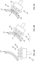
FIG. 5A, FIG. 5B, and FIG. 5C are schematic sectional illustrations of the end effector during a through thickness reinforcement process with the end effector at an angle with respect to a flat portion of the fibrous preform, in accordance with various embodiments; -
FIG. 6A, FIG. 6B, and FIG. 6C are schematic sectional illustrations of the end effector during a through thickness reinforcement process with the end effector nominally normal to a rounded portion of the fibrous preform, in accordance with various embodiments; -
FIG. 7A, FIG. 7B, and FIG. 7C are schematic sectional illustrations of the end effector during a through thickness reinforcement process with the end effector at an angle with respect to a rounded portion of the fibrous preform, in accordance with various embodiments; -
FIG. 8 is a schematic sectional illustration of an end effector having presser feet that include pivoting foot sections, in accordance with various embodiments; -
FIG. 9 is a schematic sectional illustration of an end effector having presser feet that include pivoting foot sections pivotally mounted to spherical joints, in accordance with various embodiments; -
FIG. 10 is a schematic sectional illustration of an end effector having a flexible material coupled to the ends of the presser feet, in accordance with various embodiments; -
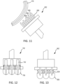
FIG. 11 is a schematic sectional illustration of an end effector having an array of retractable presser feet disposed adjacent and alternating with an array of retractable needles, in accordance with various embodiments; -
FIG. 12 is a schematic sectional illustration of an end effector having an actively controlled array of retractable presser feet, in accordance with various embodiments; -
FIG. 13 is a schematic sectional illustration of an end effector having a passively controlled array of retractable presser feet, in accordance with various embodiments; and -
FIG. 14 and FIG. 15 are a schematic sectional illustrations of end effectors having preform tensioners, in accordance with various embodiments. - The following detailed description of various embodiments herein makes reference to the accompanying drawings, which show various embodiments by way of illustration. While these various embodiments are described in sufficient detail to enable those skilled in the art to practice the disclosure, it should be understood that other embodiments may be realized and that changes may be made without departing from the scope of the disclosure. Thus, the detailed description herein is presented for purposes of illustration only and not of limitation. Furthermore, any reference to singular includes plural embodiments, and any reference to more than one component or step may include a singular embodiment or step. Also, any reference to attached, fixed, connected, or the like may include permanent, removable, temporary, partial, full or any other possible attachment option. Additionally, any reference to without contact (or similar phrases) may also include reduced contact or minimal contact. It should also be understood that unless specifically stated otherwise, references to "a," "an" or "the" may include one or more than one and that reference to an item in the singular may also include the item in the plural. Further, all ranges may include upper and lower values and all ranges and ratio limits disclosed herein may be combined.
- As used herein, the term "through thickness reinforcement" includes "needling," "stitching," and/or "tufting," in accordance with various embodiments.
- As used herein, the term "needling" includes "stitching" and/or "tufting," in accordance with various embodiments.
- With reference to
FIG. 1 , arobotic arm 100 comprising anend effector 102 is illustrated during a through thickness reinforcement process of afibrous preform 110, in accordance with various embodiments.Fibrous preform 110 may be placed over atool 115 and formed to the geometry of thetool 115. In this manner,fibrous preform 110 may be shaped into a complex contour preform (e.g., bent about one or more axes).Robotic arm 100 may be configured to move theend effector 102 with respect to thefibrous preform 110 in a controlled manner to perform a through thickness reinforcement process, i.e. Z-needling. Z-needling refers to a process comprising penetrating a composite material (e.g., fibrous preform 110) with needles and moving (e.g., by pulling or pushing) fibers from the in-plane direction and forcing them into the Z direction, where the "Z direction" as used herein refers to a direction perpendicular to the in-plane direction. For preforms having curved surfaces, the "Z-direction" refers to the direction normal to a (local) surface of the fibrous preform at the point where the preform is being needled (i.e., a direction normal to the tangent plane to the surface at the point of needling). In general, the through thickness reinforcement process has the effect of interlocking individual fabric layers together. Thus, after through thickness reinforcement, the fibrous material has fibers extending in three different directions (i.e., in the X and Y directions in the plane of the fibrous layers and the Z direction perpendicular to the fibrous layers). It should be appreciated that due to the complex contours of thefibrous preform 110, the X, Y, and Z directions vary depending on the particular location of thefibrous preform 110. - With reference to
FIG. 2 , a view of the face ofend effector 102 is illustrated, in accordance with various embodiments.End effector 102 may comprise a head orbody 104, a plurality of presser feet 106 (e.g.,first presser foot 106a,second presser foot 106b, etc.), and a plurality of needles 108 (e.g.,first needle 108a,second needle 108b, etc.).Body 104 may be made from a metal material, a composite material, or a plastic material.Body 104 may house various components for actuatingpresser feet 106 and/or needles 108.Presser feet 106 may be moveable with respect tobody 104.Presser feet 106 may be moveable with respect to needles 108.Needles 108 may be moveable with respect tobody 104.Needles 108 may be moveable with respect topresser feet 106. Aface 105 of the body may be flat or planar. Face 105 may face the fibrous preform during the through thickness reinforcement process. In various embodiments,presser feet 106 andneedles 108 extend fromface 105. - In various embodiments, each
presser foot 106 comprises a cylindrical body with a hemispherical-shaped end; thoughother presser foot 106 shapes and/or designs are contemplated herein. Eachpresser foot 106 may be made from a metal material, a rubber material, or a plastic material. The material ofpresser foot 106 may be selected based on the desired pressure exerted ontofibrous preform 110, among other factors. - In various embodiments, each
needle 108 may be made from a metal material or a polymer material or a ceramic material or combinations thereof. For example, the needle may be a metal material with a polymer coating or it may be a metal material with a ceramic coating. The material and coating system ofneedle 108 may be selected depending on the material offibrous preform 110, among other factors. - With reference to
FIG. 3 ,end effector 102 is illustrated during a through thickness reinforcement process offibrous preform 110.Fibrous preform 110 may comprise afirst layer 112 and asecond layer 114.First layer 112 may be a top layer. Each layer of material may share a common (e.g., the same) construction and/or material makeup. Each layer of material, for example, may be formed by a sheet / layer of fibrous material; e.g., woven carbon fiber, woven oxidized polyacrylonitrile (PAN) fibers, non-crimp fabric, etc. One or more or all of the layers of material may each be impregnated with a polymer matrix; e.g., thermoset material or thermoplastic material. One or more or all of the layers of material may alternatively each be unimpregnated (e.g., only include the fibrous material) where, for example, the preform material is impregnated subsequent to formation of the composite structure. The method of the present disclosure, however, is not limited to such exemplary layer materials. -
End effector 102 may be moved (e.g., via robotic arm 100) with respect tofibrous preform 110. With theend effector 102 in the desired position, one or more needles may be actuated to penetratefibrous preform 110, thereby moving one ormore fibers 113 fromfirst layer 112 intosecond layer 114 and interlockingfirst layer 112 withsecond layer 114. For example,needle 108a is illustrated inFIG. 3 moving from a non-penetrating position to a penetrating position (also referred to herein as a retracted position (seeneedle 108b) and an extended position (seeneedle 108a), respectively). In this regard, needles 108 may be referred to herein as articulating needles.Needle 108b may be similarly operated.Needles control unit 250 ofFIG. 5B and FIG. 5C ) to puncture the plies offibrous preform 110 to a desired depth and/or a desired needling density (e.g.,various needles 108 may be commanded not to penetrate the fibrous preform to vary a needling density (i.e., number of needles per unit area)). Theneedles end effector 102 may be rotated to appropriate angles to needle plies at different desired angles (e.g., seeFIG. 4A through FIG. 7C ,FIG. 14, and FIG. 15 ). -
FIG. 3 illustratespresser foot 106a in a retracted position andpresser foot 106b in an extended position, whereby thepresser feet 106. In this regard,presser feet 106 may be referred to herein as articulating presser feet. - With reference to
FIG. 4A, FIG. 4B, and FIG. 4C , anend effector 202 is illustrated during a through thickness reinforcement process offibrous preform 210, in accordance with various embodiments.End effector 202 may be similar to end effector 102 (seeFIG. 1 ) in various embodiments.FIG. 4A illustratesend effector 202 moved with respect tofibrous preform 210. For example,end effector 202 may be oriented at a desired angle with respect tofibrous preform 210.End effector 202 may be moved towardfibrous preform 210 until one ormore presser feet 206 contactfibrous preform 210. For example,presser feet 206 may exert a desired pressure onfibrous preform 210 to securefibrous preform 210 during the through thickness reinforcement process. - Each
needle 208 may be actuated independently so as to independently control a penetrating depth of eachneedle 208. For example, afirst needle 208a may actuated to penetrate a first predetermined number of layers offibrous preform 210, such as three layers for example, asecond needle 208b may actuated to penetrate a second predetermined number of layers offibrous preform 210, such as six layers for example, and athird needle 208c may actuated to penetrate a third predetermined number of layers offibrous preform 210, such as two layers for example. Although penetration of three, six, and two layers is provided as an example, any number of layers offibrous preform 210 may be penetrated byneedles 208 as desired depending on the desired amount of interlocking of adjacent layers. In this regard,first needle 208a may be actuated to penetrate a first number of layers of the fibrous preform and thesecond needle 208b may be simultaneously, or nearly simultaneously, actuated to penetrate a second number of layers of thefibrous preform 210, wherein the first number of layers is different from the second number of layers. Stated differently,first needle 208a may penetrate thefibrous preform 210 at a first depth andsecond needle 208b may penetrate thefibrous preform 210 at a second depth, different from the first depth. For example, one or more layers be omitted from the through thickness reinforcement process to allow for said layer(s) to move with respect to one another during the forming process to avoid wrinkling. In various embodiments, one or more layers may be omitted from the through thickness reinforcement process depending on the desired interlaminar preform mechanical properties, through thickness thermal conductivity, and/or other fiber dominated properties. Moreover, by independently controlling each needle, the frequency of needling may be varied as desired. Having discussed the independent control of theneedles 208, thepresser feet 206 may be similarly independently controlled. - With reference to
FIG. 5A, FIG. 5B, and FIG. 5C ,end effector 202 is illustrated during a through thickness reinforcement process offibrous preform 210, in accordance with various embodiments.FIG. 5A illustratesend effector 202 moved with respect tofibrous preform 210.FIG. 5B illustratesend effector 202 oriented at a desired angle α with respect tofibrous preform 210. In various embodiments, angle α is an angle of the centerline of aneedle 208 with respect to the fibrous preform. Angle α may be between twenty degrees and ninety degrees in accordance with various embodiments, between thirty degrees and eighty degrees in accordance with various embodiments, or between twenty five degrees and eighty degrees in accordance with various embodiments.End effector 202 may be moved towardfibrous preform 210 until one ormore presser feet 206 contactfibrous preform 210. For example,presser feet 206 may exert a desired pressure onfibrous preform 210 to securefibrous preform 210 during the through thickness reinforcement process. - In various embodiments, the
end effector 202 further includes acontrol unit 250, which includes one or more controllers (e.g., processors) and one or more tangible, non-transitory memories capable of implementing digital or programmatic logic. In various embodiments, for example, the one or more controllers are one or more of a general purpose processor, digital signal processor (DSP), application specific integrated circuit (ASIC), field programmable gate array (FPGA), or other programmable logic device, discrete gate, transistor logic, or discrete hardware components, or any various combinations thereof or the like. In various embodiments, thecontrol unit 250 controls, at least various parts of, and operation of various components of, theend effector 202. For example, thecontrol unit 250 may control a position ofend effector 202 with respect tofibrous preform 210, the position of presser feet 206 (e.g., viaactuators actuators sensors - In various embodiments,
end effector 202 further includes a touch or pressure sensor for eachpresser foot 206. For example,first presser foot 206a may comprise afirst sensor 220a,second presser foot 206b may comprise asecond sensor 220b, andthird presser foot 206c may comprise athird sensor 220c. In various embodiments, the robotic arm moves theend effector 202 toward thefibrous preform 210 until at least one sensor (e.g.,sensor 220a) detects thatpresser foot 206a has contactedfibrous preform 210. In various embodiments,control unit 250 detects (viasensor 220a) thatpresser foot 206a has contactedfibrous preform 210 and is exerting a predetermined force or pressure on thefibrous preform 210, which may ensure thatpresser foot 206a secures thefibrous preform 210 during the through thickness reinforcement process. For example, the robotic arm may monitor the pressure feedback signal fromsensor 220a and continue to press thepresser foot 206a intofibrous preform 210 until the pressure feedback signal indicates thatpresser foot 206a is exerting a pressure greater than or equal to a predetermined pressure threshold. - In various embodiments, once at least one
presser foot 206a contacts thefibrous preform 210,end effector 202 may be actuated to extendpresser foot 206b andpresser foot 206c untilcontrol unit 250 detects (viasensors presser feet presser feet sensor FIG. 5B -may comprise a touch sensors and/or a pressure sensor. In various embodiments,sensors - In various embodiments,
end effector 202 further includes an actuator for eachpresser foot 206. For example, eachpresser feet respective presser foot Actuators FIG. 5B -may be linear actuators or rotary actuators.Actuators - In various embodiments,
control unit 250 receives feedback fromsensors presser feet 206. For example,presser foot 206a may be extended until a pressure feedback signal received from the associatedsensor 220a indicates that thepresser foot 206a is exerting a predetermined pressure on thefibrous preform 210. -
FIG. 5C illustrates theneedles 208 in extended positions during the through thickness reinforcement process. In various embodiments,end effector 202 further includes an actuator for eachneedle 208. In various embodiments, each actuator may actuate a single needle or a zone of needles (e.g., a row of needles or a column of needles in accordance with various embodiments).Needles 208 may be actuated independent of the position of thepresser feet 206. In the illustrated embodiments,needles actuators respective needle - In various embodiments,
control unit 250 may monitor pressure exerted by theneedles 208 to alert for needle breaking and/or proper loading of fibers of thefibrous preform 210. - With reference to
FIG. 6A, FIG. 6B, and FIG. 6C ,end effector 202 may be particularly useful for portions offibrous preform 210 which are rounded or have complex contours due to the ability of thepresser feet 206 to conform to a curved surface of thefibrous preform 210. In the illustrated embodiment, and with particular focus onFIG. 6B ,end effector 202 may be oriented nominally normal to thesurface 211 of thefibrous preform 210. In various embodiments, a centrally locatedpresser foot 206b may first contact thesurface 211 and the surroundingpresser feet surface 211 to provide uniform pressure on the fibrous preform during the through thickness reinforcement process (seeFIG. 6C ); though in various embodiments a non-centrally located presser foot may first contact thefibrous preform 210 and centrally located presser feet may be actuated to contact thefibrous preform 210. - With particular focus on
FIG. 6C , needles 208 and/orpresser feet 206 may be configured to articulate (e.g., pivot) to maintainneedles 208 and/orpresser feet 206 nominally perpendicular to thesurface 211 of thefibrous preform 210. For example, needles 208 and/orpresser feet 206 may be mounted to a pivot, such as a ball joint or the like, to accommodate rotation of theneedles 208 and/orpresser feet 206 with respect tobody 204 ofend effector 202. - With reference to
FIG. 7A, FIG. 7B, and FIG. 7C , a through thickness reinforcement process usingend effector 202 is illustrated at a curved portion offibrous preform 210 similar toFIG. 6A through FIG. 6C , except thatend effector 202 is oriented at an angle with respect to thesurface 211 of thefibrous preform 210. In this regard, needles 208 may penetrate the plies of thefibrous preform 210 at a non-orthogonal angle during the through thickness reinforcement process. - With reference to
FIG. 8 , anend effector 302 is illustrated, in accordance with various embodiments.End effector 302 may be similar to end effector 102 (seeFIG. 1 ) in various embodiments.End effector 302 comprises a plurality ofneedles 308 and a plurality of pivotingpresser feet 306, in accordance with various embodiments. Each pivotingpresser foot 306 may comprise asupport leg 326 mounted tobody 304 and a pivotingfoot section 328 pivotally mounted to supportleg 326 via apivot 330. In this manner, pivotingfoot section 328 may pivot to apply uniform pressure on the fibrous preform during the through thickness reinforcement process. In various embodiments,needle 308 extends through a portion of pivotingfoot section 328. - With reference to
FIG. 9 , anend effector 402 is illustrated, in accordance with various embodiments.End effector 402 may be similar to end effector 102 (seeFIG. 1 ) in various embodiments.End effector 402 comprises a plurality ofneedles 408 and a plurality of pivotingpresser feet 406, in accordance with various embodiments. Each pivotingpresser foot 406 may comprise a spherical joint 426 mounted to body 404 and a pivotingfoot section 428 pivotally mounted to spherical joint 426. In this manner, pivotingfoot section 428 may pivot to apply uniform pressure on the fibrous preform during the through thickness reinforcement process. Spherical joint 426 may accommodate multi-axial rotation of pivotingfoot section 428. -
Needle 408 may extend through spherical joint 426.Needle 408 may extend through pivotingfoot section 428. In this regard, pivotingfoot section 428 may comprise anaperture 432 extending therethrough.Aperture 432 may be tapered to accommodate needle 408 (i.e., provide clearance for needle 408) as pivotingfoot section 428 pivots about spherical joint 426. Aspring member 434 may bias pivotingfoot section 428 to a centered position (e.g., wherein the central axis of pivotingfoot section 428 is generally coaxial with the central axis of needle 408).Spring member 434 may be tailored to provide a desired amount of pressure on the fibrous preform during the through thickness reinforcement process.Needle 408 and spherical joint 426 may extend at least partially throughspring member 434. In various embodiments,spring member 434 is a coil spring. It is further contemplated thatspring member 434 may be replaced with a solid link that is mechanically or electrically controlled to articulate pivotingfoot section 428. - With reference to
FIG. 10 , anend effector 502 is illustrated, in accordance with various embodiments.End effector 502 may be similar to end effector 102 (seeFIG. 1 ) in various embodiments.End effector 502 may be similar toend effector 402 except thatend effector 502 further includes a conformable,flexible material 536 extending between and to adjacentpivoting foot sections 428 to create a contiguous or discontinuous surface for uniform compression of the fibrous preform during the through thickness reinforcement process. In this manner,flexible material 536 may be provided at the ends of the pivotingfoot sections 428 such that theflexible material 536 contacts the fibrous preform during the needling process. In various embodiments,flexible material 536 comprises a flexible material such as silicone or rubber, among others. - With reference to
FIG. 11 , anend effector 602 is illustrated having an array ofretractable presser feet 606 disposed adjacent and alternating with an array ofretractable needles 608. In this manner, although various embodiments of the present disclosure are illustrated with needles coaxially aligned with (e.g., extending through) corresponding presser feet, it is further contemplated that theneedles 608 be disposed adjacent to thepresser feet 606. Thepresser feet 606 may be programmed to conform and compact the surface of thefibrous preform 210. Theneedles 608 may be programmed to penetrate thefibrous preform 210 to a desired depth. - With reference to
FIG. 12 , anend effector 702 is illustrated having an actively controlled array ofretractable presser feet 706. In this manner,actuators 722 may be provided for controlling a position of theretractable presser feet 706. - With reference to
FIG. 13 , anend effector 802 is illustrated having a passively controlled array ofretractable presser feet 806. In this manner, tunedspring members 834 may be provided for biasingpresser feet 806 toward extended positions. - With reference to
FIG. 14 and FIG. 15 ,end effectors preform tensioners tensioners tensioners leaf springs rollers tensioners needles Preform tensioners rollers leaf springs - Systems and methods of the present disclosure include a tool for producing composite preforms with tailored in-plane and interlaminar properties. Systems and methods of the present disclosure enable the ability to needle on a complex contour preform. Systems and methods of the present disclosure allow for precisely controlling and programing needling location, angle, depth, and areal density. Systems and methods of the present disclosure allow spatially varying the needling parameters to vary interlaminar versus in-plane properties based on the desired application. Systems and methods of the present disclosure enable fabrication of 2.5D and 3D complex contour composite preforms for aerospace structures. Systems and methods of the present lend themselves to fully automated fabrication to reduce costs, improve reproducibility, and scale to production rates.
- Benefits, other advantages, and solutions to problems have been described herein with regard to specific embodiments. Furthermore, the connecting lines shown in the various figures contained herein are intended to represent exemplary functional relationships and/or physical couplings between the various elements. It should be noted that many alternative or additional functional relationships or physical connections may be present in a practical system. However, the benefits, advantages, solutions to problems, and any elements that may cause any benefit, advantage, or solution to occur or become more pronounced are not to be construed as critical, required, or essential features or elements of the disclosure. The scope of the disclosure is accordingly to be limited by nothing other than the appended claims, in which reference to an element in the singular is not intended to mean "one and only one" unless explicitly so stated, but rather "one or more." Moreover, where a phrase similar to "at least one of A, B, or C" is used in the claims, it is intended that the phrase be interpreted to mean that A alone may be present in an embodiment, B alone may be present in an embodiment, C alone may be present in an embodiment, or that any combination of the elements A, Band C may be present in a single embodiment; for example, A and B, A and C, B and C, or A and B and C. Different cross-hatching is used throughout the figures to denote different parts but not necessarily to denote the same or different materials.
- Systems, methods and apparatus are provided herein. In the detailed description herein, references to "one embodiment," "an embodiment," "various embodiments," etc., indicate that the embodiment described may include a particular feature, structure, or characteristic, but every embodiment may not necessarily include the particular feature, structure, or characteristic. Moreover, such phrases are not necessarily referring to the same embodiment. Further, when a particular feature, structure, or characteristic is described in connection with an embodiment, it is submitted that it is within the knowledge of one skilled in the art to affect such feature, structure, or characteristic in connection with other embodiments whether or not explicitly described. After reading the description, it will be apparent to one skilled in the relevant art(s) how to implement the disclosure in alternative embodiments.
- Numbers, percentages, or other values stated herein are intended to include that value, and also other values that are about or approximately equal to the stated value, as would be appreciated by one of ordinary skill in the art encompassed by various embodiments of the present disclosure. A stated value should therefore be interpreted broadly enough to encompass values that are at least close enough to the stated value to perform a desired function or achieve a desired result. The stated values include at least the variation to be expected in a suitable industrial process, and may include values that are within 10%, within 5%, within 1%, within 0.1%, or within 0.01% of a stated value. Additionally, the terms "substantially," "about" or "approximately" as used herein represent an amount close to the stated amount that still performs a desired function or achieves a desired result. For example, the term "substantially," "about" or "approximately" may refer to an amount that is within 10% of, within 5% of, within 1% of, within 0.1 % of, and within 0.01% of a stated amount or value.
- Furthermore, no element, component, or method step in the present disclosure is intended to be dedicated to the public regardless of whether the element, component, or method step is explicitly recited in the claims. No claim element herein is intended to invoke 35 U.S.C. 112(f) unless the element is expressly recited using the phrase "means for." As used herein, the terms "comprises," "comprising," or any other variation thereof, are intended to cover a non-exclusive inclusion, such that a process, method, article, or apparatus that comprises a list of elements does not include only those elements but may include other elements not expressly listed or inherent to such process, method, article, or apparatus.
- Finally, it should be understood that any of the above described concepts can be used alone or in combination with any or all of the other above described concepts. Although various embodiments have been disclosed and described, one of ordinary skill in this art would recognize that certain modifications would come within the scope of this disclosure. Accordingly, the description is not intended to be exhaustive or to limit the principles described or illustrated herein to any precise form. Many modifications and variations are possible in light of the above teaching.
Claims (15)
- An end effector for through thickness reinforcement of a fibrous preform, the end effector comprising:a body;a first presser foot mounted to the body and moveable with respect to the body; anda first needle mounted to the body and moveable with respect to the body;wherein the first needle is configured to move between a first extended position and a first retracted position.
- The end effector of claim 1, wherein the first presser foot is configured to move between a second extended position and a second retracted position.
- The end effector of claim 2, further comprising a second presser foot, wherein the first presser foot is configured to articulate independent of the second presser foot.
- The end effector of claim 2 or 3, further comprising an actuator for moving the first presser foot between the second extended position and the second retracted position.
- The end effector of any preceding claim, wherein the first presser foot is moveable with respect to the first needle.
- The end effector of any preceding claim, further comprisinga second needle; anda second presser foot;wherein the first needle extends through the first presser foot and the second needle extends through the second presser foot.
- The end effector of any preceding claim, wherein the first presser foot comprises a pivoting foot section pivotally mounted to a spherical joint.
- The end effector of claim 7, further comprising a flexible material provided at an end of the pivoting foot section, wherein the flexible material extends between adjacent pivoting foot sections.
- The end effector of any preceding claim,further comprising a spring member configured to bias at the first presser foot; and/orfurther comprising an actuator for moving the first needle between the first extended position and the first retracted position.
- The end effector of any preceding claim, further comprising a preform tensioner configured to contact the fibrous preform to apply tension to the fibrous preform while the needle moves between the first extended position to the first retracted position.
- A method for performing a process of through thickness reinforcement in a fibrous preform, the method comprising:moving an end effector with respect to the fibrous preform;moving the end effector toward the fibrous preform until a first presser foot of the end effector contacts the fibrous preform;moving a first needle of the end effector from a first retracted position to a first extended position;penetrating the fibrous preform with the first needle in response to the first needle moving from the first retracted position to the first extended position; andmoving at least a portion of a fiber from a first layer of the fibrous preform into a second layer of the fibrous preform in response to the first needle penetrating the fibrous preform.
- The method of claim 11,
further comprising:receiving, by a control unit, a feedback signal from a sensor indicating a pressure exerted by the first presser foot onto the fibrous preform; and/orfurther comprising:orienting the first needle at a non-orthogonal angle with respect to the fibrous preform; andmoving a second presser foot of the end effector from a second retracted position to a second extended position; and/orfurther comprising:
receiving, by a control unit, a feedback signal from a sensor indicating a pressure exerted by the first needle onto the fibrous preform. - A method for performing a needling process on a fibrous preform, the method comprising:moving an end effector with respect to the fibrous preform;moving the end effector toward the fibrous preform until a first presser foot of the end effector contacts the fibrous preform;receiving a first pressure signal from a first sensor indicating a first pressure applied by the first presser foot onto the fibrous preform;moving a second presser foot of the end effector from a first retracted position to a first extended position;receiving a second pressure signal from a second sensor indicating a second pressure applied by the second presser foot onto the fibrous preform;moving a first needle of the end effector from a second retracted position to a second extended position;moving a second needle of the end effector from a third retracted position to a third extended position;penetrating the fibrous preform with the first needle in response to the first needle moving from the second retracted position to the second extended position;penetrating the fibrous preform with the second needle in response to the second needle moving from the third retracted position to the third extended position;moving at least a portion of a first fiber from a first layer of the fibrous preform into a second layer of the fibrous preform in response to the first needle penetrating the fibrous preform; andmoving at least a portion of a second fiber from the first layer of the fibrous preform into the second layer of the fibrous preform in response to the second needle penetrating the fibrous preform.
- The method of claim 13, further comprising:moving the end effector toward the fibrous preform until the first pressure signal indicates the first pressure applied by the first presser foot is equal to or greater than a predetermined pressure threshold,optionally, further comprising:
continuing to extend the second presser foot until the second pressure signal indicates the second pressure applied by the second presser foot is equal to or greater than the predetermined pressure threshold. - The method of claim 13 or 14, further comprising:pivoting the first presser foot in response to the first presser foot contacting the fibrous preform; and/orfurther comprising:penetrating the fibrous preform at a first depth in response to moving the first needle to the second extended position; andpenetrating the fibrous preform at a second depth in response to moving the second needle of the end effector to the third extended position;wherein the first depth is different from the second depth.
Applications Claiming Priority (1)
| Application Number | Priority Date | Filing Date | Title |
|---|---|---|---|
| US17/978,104 US12404616B2 (en) | 2022-10-31 | 2022-10-31 | Systems and methods for robotic arm end effector for tailored through thickness reinforcement |
Publications (2)
| Publication Number | Publication Date |
|---|---|
| EP4371746A2 true EP4371746A2 (en) | 2024-05-22 |
| EP4371746A3 EP4371746A3 (en) | 2024-08-07 |
Family
ID=88505130
Family Applications (1)
| Application Number | Title | Priority Date | Filing Date |
|---|---|---|---|
| EP23204626.8A Withdrawn EP4371746A3 (en) | 2022-10-31 | 2023-10-19 | Systems and methods for robotic arm end effector for tailored through thickness reinforcement |
Country Status (2)
| Country | Link |
|---|---|
| US (1) | US12404616B2 (en) |
| EP (1) | EP4371746A3 (en) |
Families Citing this family (3)
| Publication number | Priority date | Publication date | Assignee | Title |
|---|---|---|---|---|
| EP4534747B1 (en) * | 2022-03-14 | 2026-05-13 | Arianegroup Sas | Needling system for manufacturing a textile preform |
| US12576542B2 (en) * | 2022-07-05 | 2026-03-17 | Lamus Enterprises Inc. | Helical pin gripper |
| US12460331B1 (en) * | 2024-11-13 | 2025-11-04 | Q-Carbon Material Co., Ltd. | Right-angle needle-punching mechanisms and needle-punching devices |
Family Cites Families (75)
| Publication number | Priority date | Publication date | Assignee | Title |
|---|---|---|---|---|
| US1686439A (en) | 1923-03-07 | 1928-10-02 | Nicholas W Mathey | Blower attachment for machines |
| US1623075A (en) | 1924-06-30 | 1927-04-05 | Chester L Thomas | Presser foot |
| US2601432A (en) * | 1949-11-12 | 1952-06-24 | American Hair & Felt Company | Felt punching machine |
| US2556406A (en) | 1950-01-25 | 1951-06-12 | Wapner Morris | Presser foot needle guard for sewing machines |
| US2690149A (en) | 1952-07-05 | 1954-09-28 | Coats & Clark | Needle cooler |
| US3022813A (en) * | 1957-07-25 | 1962-02-27 | Glover Benjamin Marshall | Method of making bonded non-woven fabric from textile fibers |
| US2896303A (en) * | 1958-04-16 | 1959-07-28 | Hunter James Machine Co | Needle loom |
| US3404646A (en) * | 1965-08-24 | 1968-10-08 | Frederic P Worthen | Method and apparatus for feeding textile materials in a sewing machine |
| US3729785A (en) | 1967-04-04 | 1973-05-01 | Sommer Sa Soc | Textile, web needling device |
| US3611958A (en) | 1969-08-05 | 1971-10-12 | Collins & Aikman Corp | Apparatus for the manufacture of tufted fabrics |
| US3605223A (en) | 1969-11-26 | 1971-09-20 | Richard Dilo | Apparatus for felting non-woven webs |
| GB1422546A (en) | 1973-04-06 | 1976-01-28 | Weldstow Ltd | Needle looms |
| IT983801B (en) | 1973-04-12 | 1974-11-11 | Virginio Rimoldi E C Spa | UNIVERSAL SUPPORT FOR NEEDLE COOLER UNIT OF A SEWING MACHINE |
| AT326928B (en) * | 1973-09-18 | 1976-01-12 | Fehrer Ernst Gmbh | NEEDLE MACHINE FOR FIBER FIBER FIBER |
| US4353158A (en) * | 1977-12-16 | 1982-10-12 | I.W.S. Nominee Company Limited | Method for converting a lockstitch sewing machine to a machine for decorating fabrics |
| US4369723A (en) | 1978-10-26 | 1983-01-25 | Opelika Manufacturing Corporation | Needle lubricator system |
| US4305339A (en) | 1979-09-28 | 1981-12-15 | Vortec Corporation | Vortex tube assembly for cooling sewing machine needle |
| US4777706A (en) * | 1987-09-14 | 1988-10-18 | Morrison Berkshire, Inc. | Apparatus for manufacturing endless needled paper machine felts |
| DE3824341A1 (en) | 1988-07-18 | 1990-01-25 | Dilo Kg Maschf Oskar | DEVICE ON NEEDLE MACHINES FOR THE PRODUCTION OF NEEDLE FELT COVERS OD. DGL. |
| EP0484391B1 (en) | 1989-07-25 | 1995-09-20 | Dunlop Limited | Manufacture of carbon fibre preform |
| AT392984B (en) | 1990-03-20 | 1991-07-25 | Fehrer Textilmasch | NEEDLE MACHINE |
| FR2669941B1 (en) | 1990-12-03 | 1993-03-19 | Europ Propulsion | INSTALLATION FOR PRODUCING NEEDLE FIBROUS PREFORMS FOR THE MANUFACTURE OF PARTS MADE OF COMPOSITE MATERIAL. |
| US5564355A (en) | 1992-01-30 | 1996-10-15 | Mim Industries, Inc. | Rotatable presser foot for use in a sewing machine |
| AT400043B (en) * | 1994-03-23 | 1995-09-25 | Fehrer Ernst | DEVICE FOR NEEDING A FLEECE |
| FR2718759B1 (en) * | 1994-04-18 | 1996-06-14 | Aerospatiale | Stitching head and machine for producing a plate-shaped reinforcement for a piece of composite material. |
| AT400852B (en) | 1994-05-02 | 1996-04-25 | Fehrer Textilmasch | DEVICE FOR NEEDING A CIRCULAR, IN PARTICULAR CIRCULAR FIBER PAD |
| US5800672A (en) | 1994-06-07 | 1998-09-01 | Aztex, Inc. | Ultrasonic fastening system and method |
| US6405417B1 (en) | 1994-07-25 | 2002-06-18 | Goodrich Corporation | Process for forming fibrous structures with predetermined Z-fiber distributions |
| AT402205B (en) | 1995-10-18 | 1997-03-25 | Fehrer Textilmasch | DEVICE FOR NEEDING A FLEECE |
| DE19702692A1 (en) | 1996-02-19 | 1997-11-06 | Fehrer Ernst | Method and device for needling a nonwoven web |
| DE19755449A1 (en) * | 1996-12-23 | 1998-06-25 | Fehrer Ernst | Method and device for needling a nonwoven web |
| DE19819733A1 (en) | 1997-05-15 | 1998-11-19 | Fehrer Ernst | Device for needling a fleece |
| DE19730532A1 (en) * | 1997-07-16 | 1999-01-21 | Dilo Kg Maschf Oskar | Needle machine |
| DE19918169A1 (en) * | 1999-04-21 | 2000-10-26 | Zsk Stickmasch Gmbh | Presser foot on sewing or embroidery machine has interceptor to limit pressure with adjustment for distance relative to needle plate |
| FR2794138B1 (en) | 1999-05-26 | 2001-07-27 | Dewavrin Fils Et Cie A | DEVICE FOR DRAWING WIRES FORMED FROM TEXTILE FIBERS |
| US6233797B1 (en) | 1999-07-13 | 2001-05-22 | Groz Beckert Kg | Felt needle |
| FR2807354B1 (en) * | 2000-04-11 | 2002-07-12 | Asselin | ASSEMBLY AND DISASSEMBLY DEVICE FOR A MACHINE PART, AND NEEDLE THUS EQUIPPED. |
| FR2825382B1 (en) * | 2001-06-05 | 2003-09-12 | Messier Bugatti | METHOD FOR REAL-TIME CHECKING THE NEEDLE OF FIBROUS STRUCTURES AND NEEDLE DEVICE FOR ITS IMPLEMENTATION |
| AT409868B (en) * | 2001-06-12 | 2002-12-27 | Fehrer Textilmasch | DEVICE FOR NEEDING A FLEECE |
| US6374469B1 (en) * | 2001-06-13 | 2002-04-23 | Messier-Bugatti | Needling machine provided with a device for measuring penetration |
| FR2833204B1 (en) | 2001-12-11 | 2004-05-28 | Snecma | REALIZATION OF NEEDLE FIBROUS PREFORM FOR MANUFACTURING A PART OF COMPOSITE MATERIAL |
| US20030209179A1 (en) | 2002-05-07 | 2003-11-13 | Michelle Scordos | Foot for a quilting machine |
| FR2842835B1 (en) | 2002-07-26 | 2005-01-14 | Asselin | METHOD FOR LIMITING THE ENCRASSMENT OF A NEEDLEFILLER BY FLYING FIBERS AND A NEEDLEFOLDER USING SAID METHOD |
| US20070149080A1 (en) | 2004-03-30 | 2007-06-28 | Nobuo Asahara | Preform, frp, and processes for producing these |
| KR100733610B1 (en) | 2005-05-19 | 2007-06-28 | 주식회사유풍 | Presser foot and sewing machine using the same |
| US7497001B2 (en) | 2005-06-22 | 2009-03-03 | Northrop Grumman Corporation | Technique for predicting over insertions for partial grids and defective Z-pins |
| FR2924426B1 (en) | 2007-11-30 | 2011-06-03 | Messier Bugatti | PROCESS FOR MANUFACTURING COMPOSITE MATERIAL PARTS WITH CARBON FIBER REINFORCEMENT |
| JP4623142B2 (en) * | 2008-06-05 | 2011-02-02 | ブラザー工業株式会社 | sewing machine |
| JP5318547B2 (en) * | 2008-12-04 | 2013-10-16 | Juki株式会社 | sewing machine |
| US20120153528A1 (en) | 2010-12-17 | 2012-06-21 | Honeywell International Inc. | Apparatus for carbon fiber processing and pitch densification |
| WO2012107486A1 (en) * | 2011-02-08 | 2012-08-16 | Hi Tech Textile Holding Gmbh | Method and device for strengthening a continuously fed material web |
| JP2013202145A (en) | 2012-03-28 | 2013-10-07 | Brother Ind Ltd | sewing machine |
| US8991020B2 (en) * | 2012-04-03 | 2015-03-31 | Simplicity Pattern Co. Inc. | Hand held felting machine |
| JP6129849B2 (en) | 2012-08-29 | 2017-05-17 | エヌエスディ株式会社 | Needle bar and sewing machine |
| DE202013105848U1 (en) | 2013-12-20 | 2015-03-24 | Rehau Ag + Co. | Device for gripping a flat semifinished product and transport device |
| JP6552233B2 (en) * | 2015-03-20 | 2019-07-31 | 蛇の目ミシン工業株式会社 | sewing machine |
| JP6861934B2 (en) * | 2016-04-05 | 2021-04-21 | ヤマトミシン製造株式会社 | Sewing machine with automatic stop device for detecting the end of sewing |
| CN105755679B (en) * | 2016-04-25 | 2017-10-10 | 天津工大航泰复合材料有限公司 | A kind of portable pneumatic acupuncture rifle |
| US10448706B2 (en) | 2016-10-18 | 2019-10-22 | Nike, Inc. | Systems and methods for manufacturing footwear with felting |
| FR3064284B1 (en) * | 2017-03-27 | 2019-04-19 | Airbus Safran Launchers Sas | INSTALLATION AND METHOD FOR NEEDLEING A FIBROUS PREFORM WITH CONTROL OF CONTACT PRESSURE OF THE DEBOUREUR |
| WO2019107579A1 (en) | 2017-11-28 | 2019-06-06 | 주식회사 하이인텍 | Fiber stacking apparatus and method for manufacturing direct preform |
| CN108103671A (en) | 2018-02-01 | 2018-06-01 | 天津工业大学 | A kind of robot acupuncture apparatus based on servo pin tartar's unit |
| CN108789447B (en) | 2018-07-19 | 2023-12-19 | 常州善巧复合材料科技有限公司 | Mute needling robot and constant arc length linkage control method thereof |
| KR101935743B1 (en) * | 2018-08-10 | 2019-01-04 | 박진성 | Non-woven needle punching machine that can uniformly punch |
| CN209779164U (en) | 2018-12-19 | 2019-12-13 | 河南凯辉实业有限公司 | Environment-friendly needle machine for processing biomass fiber products |
| US11008684B2 (en) * | 2019-05-06 | 2021-05-18 | Handi Quilter, Inc. | Felting assembly for a quilting machine |
| CN110219097A (en) | 2019-06-13 | 2019-09-10 | 合肥汇之新机械科技有限公司 | A kind of weaving automatically cleaning needing machine |
| CN213951536U (en) * | 2020-08-21 | 2021-08-13 | 保山隆基硅材料有限公司 | Acupuncture device |
| CN112318499A (en) | 2020-10-16 | 2021-02-05 | 西安工程大学 | Special-shaped prefabricated body robot needling forming path planning method |
| US11701816B2 (en) | 2020-12-15 | 2023-07-18 | Northrop Grumman Systems Corporation | Process for reinforcing continuous fiber additively manufactured laminates |
| FR3126715B1 (en) | 2021-09-06 | 2025-06-06 | Andritz Asselin Thibeau | Installation forming a needling machine for needling a sheet or a veil of fibers, in particular non-woven |
| CN114474958B (en) | 2022-02-14 | 2023-03-24 | 宜兴市飞舟高新科技材料有限公司 | Forming process and forming device of carbon fiber preform |
| CN114703605B (en) | 2022-04-07 | 2022-11-11 | 浙江星辉新材料科技有限公司 | A kind of linkage needle punch forming equipment for carbon fiber |
| CN115094575B (en) * | 2022-07-11 | 2023-10-03 | 天津工业大学 | A hybrid switching dual-station acupuncture robot |
| US12297573B2 (en) | 2023-05-12 | 2025-05-13 | Rohr, Inc. | Systems and methods for through thickness reinforcement using roll-to-roll veil cloth |
-
2022
- 2022-10-31 US US17/978,104 patent/US12404616B2/en active Active
-
2023
- 2023-10-19 EP EP23204626.8A patent/EP4371746A3/en not_active Withdrawn
Also Published As
| Publication number | Publication date |
|---|---|
| EP4371746A3 (en) | 2024-08-07 |
| US20240141571A1 (en) | 2024-05-02 |
| US12404616B2 (en) | 2025-09-02 |
Similar Documents
| Publication | Publication Date | Title |
|---|---|---|
| US12404616B2 (en) | Systems and methods for robotic arm end effector for tailored through thickness reinforcement | |
| JP4874335B2 (en) | Apparatus for producing a fiber structure preform having a desired surface shape by a TFP process | |
| CA2895564C (en) | Fabric handling apparatus | |
| EP4375038A1 (en) | Methods for selective needling of fibrous preforms for shape-forming | |
| US5829373A (en) | Blind stitching apparatus and composite material manufacturing methods | |
| CN105916787B (en) | Fabric positioning device | |
| CA2056769C (en) | An installation for making needled fiber preforms for use in manufacturing parts made of composite material | |
| JP2009502548A (en) | Method for producing a single-layer or multi-layer fiber preform by the TFP method | |
| EP2903802A1 (en) | Method of composite tape lamination over convex radii | |
| GB2635039A (en) | Forming a curvature into a charge | |
| EP4261022A1 (en) | Apparatus, system and method for applying composite layups | |
| EP3434436B1 (en) | Device and method for producing a curved fibre preform from a bi- or multidirectional fibre semi-finished product | |
| US12539685B2 (en) | Composite structures, forming apparatuses and related systems and methods | |
| US12428764B2 (en) | Systems and methods for non-linear through thickness reinforcement | |
| US20200368946A1 (en) | Conformable apparatus, systems and methods for treating a composite material | |
| EP4361330B1 (en) | Systems and methods for self-cleaning needles for through thickness reinforcement of resin-infused fabrics | |
| JP2003201644A (en) | Method for making multidirectional textile preform, device for practicing the method and preform thus obtained | |
| US20230166462A1 (en) | Method for manufacturing a three-dimensional preform | |
| CN115923184A (en) | Composite forming apparatus, method and system |
Legal Events
| Date | Code | Title | Description |
|---|---|---|---|
| PUAI | Public reference made under article 153(3) epc to a published international application that has entered the european phase |
Free format text: ORIGINAL CODE: 0009012 |
|
| STAA | Information on the status of an ep patent application or granted ep patent |
Free format text: STATUS: THE APPLICATION HAS BEEN PUBLISHED |
|
| AK | Designated contracting states |
Kind code of ref document: A2 Designated state(s): AL AT BE BG CH CY CZ DE DK EE ES FI FR GB GR HR HU IE IS IT LI LT LU LV MC ME MK MT NL NO PL PT RO RS SE SI SK SM TR |
|
| PUAL | Search report despatched |
Free format text: ORIGINAL CODE: 0009013 |
|
| AK | Designated contracting states |
Kind code of ref document: A3 Designated state(s): AL AT BE BG CH CY CZ DE DK EE ES FI FR GB GR HR HU IE IS IT LI LT LU LV MC ME MK MT NL NO PL PT RO RS SE SI SK SM TR |
|
| RIC1 | Information provided on ipc code assigned before grant |
Ipc: D04H 18/02 20120101ALN20240702BHEP Ipc: B25J 15/00 20060101ALI20240702BHEP Ipc: B32B 7/09 20190101ALI20240702BHEP Ipc: B29C 70/38 20060101ALI20240702BHEP Ipc: B29C 65/56 20060101ALI20240702BHEP Ipc: B29C 70/24 20060101AFI20240702BHEP |
|
| STAA | Information on the status of an ep patent application or granted ep patent |
Free format text: STATUS: REQUEST FOR EXAMINATION WAS MADE |
|
| 17P | Request for examination filed |
Effective date: 20250129 |
|
| STAA | Information on the status of an ep patent application or granted ep patent |
Free format text: STATUS: THE APPLICATION HAS BEEN WITHDRAWN |
|
| 18W | Application withdrawn |
Effective date: 20260106 |