EP4371730A1 - Mold clamping device and injection molding machine - Google Patents
Mold clamping device and injection molding machine Download PDFInfo
- Publication number
- EP4371730A1 EP4371730A1 EP22841848.9A EP22841848A EP4371730A1 EP 4371730 A1 EP4371730 A1 EP 4371730A1 EP 22841848 A EP22841848 A EP 22841848A EP 4371730 A1 EP4371730 A1 EP 4371730A1
- Authority
- EP
- European Patent Office
- Prior art keywords
- platen
- rotary
- bearing structure
- mold clamping
- extrusion device
- Prior art date
- Legal status (The legal status is an assumption and is not a legal conclusion. Google has not performed a legal analysis and makes no representation as to the accuracy of the status listed.)
- Pending
Links
Images



Classifications
-
- B—PERFORMING OPERATIONS; TRANSPORTING
- B29—WORKING OF PLASTICS; WORKING OF SUBSTANCES IN A PLASTIC STATE IN GENERAL
- B29C—SHAPING OR JOINING OF PLASTICS; SHAPING OF MATERIAL IN A PLASTIC STATE, NOT OTHERWISE PROVIDED FOR; AFTER-TREATMENT OF THE SHAPED PRODUCTS, e.g. REPAIRING
- B29C45/00—Injection moulding, i.e. forcing the required volume of moulding material through a nozzle into a closed mould; Apparatus therefor
- B29C45/17—Component parts, details or accessories; Auxiliary operations
- B29C45/40—Removing or ejecting moulded articles
- B29C45/4005—Ejector constructions; Ejector operating mechanisms
-
- B—PERFORMING OPERATIONS; TRANSPORTING
- B29—WORKING OF PLASTICS; WORKING OF SUBSTANCES IN A PLASTIC STATE IN GENERAL
- B29C—SHAPING OR JOINING OF PLASTICS; SHAPING OF MATERIAL IN A PLASTIC STATE, NOT OTHERWISE PROVIDED FOR; AFTER-TREATMENT OF THE SHAPED PRODUCTS, e.g. REPAIRING
- B29C45/00—Injection moulding, i.e. forcing the required volume of moulding material through a nozzle into a closed mould; Apparatus therefor
- B29C45/03—Injection moulding apparatus
- B29C45/04—Injection moulding apparatus using movable moulds or mould halves
- B29C45/0441—Injection moulding apparatus using movable moulds or mould halves involving a rotational movement
-
- B—PERFORMING OPERATIONS; TRANSPORTING
- B29—WORKING OF PLASTICS; WORKING OF SUBSTANCES IN A PLASTIC STATE IN GENERAL
- B29C—SHAPING OR JOINING OF PLASTICS; SHAPING OF MATERIAL IN A PLASTIC STATE, NOT OTHERWISE PROVIDED FOR; AFTER-TREATMENT OF THE SHAPED PRODUCTS, e.g. REPAIRING
- B29C45/00—Injection moulding, i.e. forcing the required volume of moulding material through a nozzle into a closed mould; Apparatus therefor
- B29C45/17—Component parts, details or accessories; Auxiliary operations
- B29C45/64—Mould opening, closing or clamping devices
-
- B—PERFORMING OPERATIONS; TRANSPORTING
- B29—WORKING OF PLASTICS; WORKING OF SUBSTANCES IN A PLASTIC STATE IN GENERAL
- B29C—SHAPING OR JOINING OF PLASTICS; SHAPING OF MATERIAL IN A PLASTIC STATE, NOT OTHERWISE PROVIDED FOR; AFTER-TREATMENT OF THE SHAPED PRODUCTS, e.g. REPAIRING
- B29C33/00—Moulds or cores; Details thereof or accessories therefor
- B29C33/20—Opening, closing or clamping
- B29C33/22—Opening, closing or clamping by rectilinear movement
-
- B—PERFORMING OPERATIONS; TRANSPORTING
- B29—WORKING OF PLASTICS; WORKING OF SUBSTANCES IN A PLASTIC STATE IN GENERAL
- B29C—SHAPING OR JOINING OF PLASTICS; SHAPING OF MATERIAL IN A PLASTIC STATE, NOT OTHERWISE PROVIDED FOR; AFTER-TREATMENT OF THE SHAPED PRODUCTS, e.g. REPAIRING
- B29C33/00—Moulds or cores; Details thereof or accessories therefor
- B29C33/44—Moulds or cores; Details thereof or accessories therefor with means for, or specially constructed to facilitate, the removal of articles, e.g. of undercut articles
Definitions
- the present invention relates to a mold clamping device including a rotary platen that rotates a mold and an extrusion device that extrudes a molded article, and an injection molding machine.
- a mold clamping device provided in an injection molding machine includes a fixed platen and a movable platen that is opened and closed with respect to the fixed platen.
- the rotary platen is provided on one surface of the movable platen, and a plurality of molds, that is, rotary-side molds are attached to the rotary platen.
- a rotation position of the rotary platen is changed and the molds are clamped, another rotary-side mold is clamped with the fixed-side mold.
- Patent Literature 1 JP2009-45939A
- the rotary platen includes a rotary shaft.
- the rotary shaft is inserted into a through hole formed at the center of the movable platen.
- the rotary platen is provided on the one surface of the movable platen, while a drive mechanism for driving the rotary platen is provided on the other surface of the movable platen.
- the drive mechanism rotates the rotary shaft to rotate the rotary platen.
- the mold clamping device includes an extrusion device to extrude a finished molded article.
- the extrusion device is provided on the movable platen.
- the extrusion device is configured such that one or a plurality of ejector rods protrude from rod holes passing through the movable platen.
- the rotary platen is provided on the movable platen
- the rotary shaft of the rotary platen is provided at the center of the movable platen.
- the ejector rod cannot protrude from the vicinity of the center of the movable platen, that is, from the vicinity of the center of the rotary platen. That is, there is a problem that a protruding position of the ejector rod is restricted.
- an object of the present disclosure is to provide a mold clamping device in which a rotary platen is provided and an ejector rod can protrude from any arbitrary location.
- a rotary platen and an extrusion device are provided to one platen of a fixed platen and a movable platen.
- the rotary platen is provided to the one platen at a side of a surface facing the other platen, and the extrusion device is provided on an opposite surface thereof.
- a bearing structure is provided between the rotary platen and the one platen. The bearing structure is configured to bear the rotary platen at a position away from a rotation center in a radial direction.
- An ejector rod is provided radially inward than the bearing structure.
- the one platen is the movable platen, and the other platen is the fixed platen.
- an injection molding machine 1 includes a mold clamping device 2 configured to clamp a mold, an injection device 3 configured to melt and inject an injection material, a rotary platen 4 provided on the mold clamping device 2, and an extrusion device 10 for extruding a molded article.
- the mold clamping device 2 includes a fixed platen 5 fixed on a bed B, a mold clamping housing 6 that slides on the bed B, and a movable platen 7 that also slides on the bed B.
- the fixed platen 5 and the mold clamping housing 6 are coupled by a plurality of, for example, four tie bars 9, 9 ...
- the movable platen 7 is slidable between the fixed platen 5 and the mold clamping housing 6.
- a mold clamping mechanism 11 is provided between the mold clamping housing 6 and the movable platen 7.
- the mold clamping mechanism 11 may be implemented by a direct pressure type mold clamping mechanism, that is, a mold clamping cylinder. In the present illustrative embodiment, the mold clamping mechanism 11 is implemented by a toggle mechanism.
- the rotary platen 4 according to the present illustrative embodiment is provided on the movable platen 7.
- the fixed platen 5 is provided with a fixed-side mold 13.
- the rotary platen 4 is provided with two rotary-side molds 14, 14.
- the two rotary-side molds 14, 14 attached to the rotary platen 4 are provided on a front side and a back side of the paper surface, and are shown in an overlapping manner.
- One of the two rotary-side molds 14, 14 is aligned with the fixed-side mold 13 according to a rotation position of the rotary platen 4.
- the fixed-side mold 13 and one rotary-side mold 14 aligned therewith are opened and closed.
- the extrusion device 10 is also provided on the movable platen 7. Specifically, the extrusion device 10 is provided on the movable platen 7 not on the surface where the rotary platen 4 is provided but on a surface opposite thereto. The extrusion device 10 extrudes a molded article formed in the rotary-side molds 14, 14.
- the injection device 3 includes a heating cylinder 16, a screw 17 inserted in the heating cylinder 16, and a screw driving device 18 configured to drive the screw 17.
- a hopper 20 is provided in the vicinity of a rear end portion of the heating cylinder 16.
- An injection nozzle 22 is provided at a tip end of the heating cylinder 16.
- the rotary platen 4 is provided on the movable platen 7 as described above.
- FIG. 2 shows the rotary platen 4 and the movable platen 7 when viewed from a direction perpendicular to the rotary platen 4.
- the rotary platen 4 rotates smoothly with respect to the movable platen 7.
- a rotary platen driving mechanism 25 is provided above the movable platen 7.
- a pulley 24 having a diameter slightly larger than that of the rotary platen 4 is fixed to the rotary platen 4.
- a belt 26 is wound around the pulley 24 and the rotary platen driving mechanism 25. When the rotary platen driving mechanism 25 is driven, the pulley 24 and the rotary platen 4 rotate integrally.
- a friction reducing plate-form member is provided on a surface of either one of the rotary platen and the one platen provided with the rotary platen facing the other.
- the movable platen 7 is formed with a protrusion 28 that rises in a cylindrical shape at a central portion thereof.
- the protrusion 28 is formed on a surface of the movable platen 7 closer to the fixed platen 5 (see FIG. 1 ).
- the friction reducing plate-form member is provided on an upper surface of the protrusion 28.
- the friction reducing plate-form member is made of a wear plate 30 formed by sintering a solid lubricant mainly composed of graphite uniformly dispersed in an alloy.
- a diameter of the protrusion 28 is smaller than a diameter of the rotary platen 4, but is sufficiently large in the movable platen 7, and the protrusion 28 largely occupies a central portion of the movable platen 7. Further, an area of the wear plate 30 also increases.
- the rotary platen 4 is slightly elastically deformed by a mold clamping force received from the rotary-side mold 14, and comes into close contact with the wear plate 30. Since the protrusion 28 and the wear plate 30 have a sufficiently large area, the mold clamping force appropriately acts on the movable platen 7.
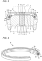
- the rotary platen 4 is formed with a circular recess 32 on a side facing the movable platen 7 as shown in FIG. 3 .
- the protrusion 28 of the movable platen 7 is accommodated in the recess 32.
- a flange portion 35 is formed on a circumferential portion of the rotary platen 4.
- a slightly raised base portion 33 is formed on a surface of the recess 32, that is, on a surface of the rotary platen 4 that faces the wear plate 30.
- a slight gap is secured between the base portion 33 and the wear plate 30 so as not to come into contact with each other when the rotary platen 4 rotates.
- the rotary platen 4 is slightly elastically deformed by the mold clamping force received from the rotary-side mold 14, and the base portion 33 and the wear plate 30 are brought into close contact with each other. That is, it is described above that the rotary platen 4 comes into close contact with the wear plate 30 during mold clamping, and the rotary platen 4 comes into close contact with the wear plate 30 at the base portion 33.
- a cylindrical protrusion is fixedly installed to the one platen, to which the rotary platen is provided, on the surface facing the other platen, a circular recess for accommodating the protrusion is formed on a surface of the rotary platen which faces the one platen, and the bearing structure connects the one platen and the rotary platen to each other in a circumferential portion of the protrusion and a circumferential portion of the recess.
- the rotary platen 4 is rotatably supported by a bearing structure 36 on the flange portion 35 thereof with respect to the cylindrical protrusion 28 of the movable platen 7. That is, the bearing structure 36 is provided not in the vicinity of the center but on a peripheral portion of the rotary platen 4. In other words, the bearing structure 36 bears the rotary platen 4 with respect to the movable platen 7 at a position away from a rotation center of the rotary platen 4 in a radial direction. Therefore, as will be explained later, there are no restrictions on the arrangement of ejector rods 37, 37, ...
- the bearing structure is a cross roller ring including an inner ring, an outer ring that is rotatable relative to the inner ring, and a plurality of rollers provided between the inner ring and the outer ring.
- the bearing structure 36 is implemented by a cross roller ring 36 shown in FIG. 4 .
- the cross roller ring 36 is a bearing component having a special shape.
- the cross roller ring 36 has a ring shape as a whole.
- the cross roller ring 36 includes an outer ring 36a, a pair of inner rings 36b, 36b, and a large number of rollers 36c, 36c, ... interposed therebetween.
- the rollers 36c, 36c, ... have a cylindrical shape and roll between the outer ring 36a and the pair of inner rings 36b, 36b. Therefore, in the cross roller ring 36, the pair of inner rings 36b, 36b rotate smoothly relative to the outer ring 36a.
- the cross roller ring 36 is provided on an outer periphery of the protrusion 28 of the movable platen 7.
- the pair of inner rings 36b, 36b are fixed by the pressing member 38.
- the outer ring 36a of the cross roller ring 36 is provided on the circumferential portion of the rotary platen 4. That is, the pulley 24 having a large diameter is provided on the flange portion 35 of the rotary platen 4.
- the outer ring 36a is fixed by the flange portion 35 and the pulley 24. As a result, the rotary platen 4 can smoothly rotate relative to the movable platen 7.
- the extrusion device is provided to the one platen to which the rotary platen is provided on a surface opposite to the surface facing the other platen, radially inward than the bearing structure.
- the extrusion device 10 is provided on the surface of the movable platen 7 that is opposite to the surface to which the rotary platen 4 is provided. More specifically, the extrusion device 10 is provided at the central portion of the movable platen 7. This is because the rotary platen driving mechanism 25 (see FIGS. 1 and 2 ) for driving the rotary platen 4 does not interfere with the arrangement of the extrusion device 10.
- the extrusion device 10 includes the plurality of ejector rods 37, 37, ...
- the movable platen 7 has ejector rod holes 31, 31, ...
- the rotary platen 4 also has ejector rod holes 34, 34, ...
- the ejector rods 37, 37, ... are inserted into the ejector rod holes 31, 31, ...
- the rotary platen 4 is at an appropriate rotation position, the ejector rod holes 31, 31, ... are aligned with the ejector rod holes 34, 34, ...
- the ejector rods 37, 37, ... protrude from the extrusion device 10, the molded article is extruded from the rotary-side mold 14.
- all of the ejector rods 37, 37, ... protrude radially inward than the bearing structure 36 in the movable platen 7 as indicated by reference numeral 41.
- the bearing structure 36 bearing the rotary platen 4 is provided on the circumferential portion of the rotary platen 4, so that the bearing structure 36 does not interfere with the arrangement of the ejector rods 37, 37, ... and there are no restrictions on the arrangement.
- one of the ejector rods 37, 37, ... is provided at the rotation center of the rotary platen 4 as indicated by reference numeral 40 in FIG. 3 .
- a movable platen 72 including a related-art rotary platen 71 is shown in FIG. 5 .
- a rotary shaft 74 is fixed to the center of the related-art rotary platen 71.
- a through hole 75 is formed in the center of the movable platen 72, and the rotary shaft 74 is inserted into the through hole 75 via bearings 77 and 77. That is, the bearings 77 and 77 serve as bearing structures for rotatably bearing the rotary platen 71.
- a drive mechanism 78 is provided at the center of a back surface of the movable platen 72, and rotates the rotary platen 71 is via the rotary shaft 74.
- the rotary platen 71 is pressed by a pressing member 81 provided on a front surface of the movable platen 72 so as not to be released when the mold is opened.
- the drive mechanism 78 of the rotary platen 71 is disposed at the center as described above. Therefore, an extrusion device 83 needs to be placed on the back surface of the movable platen 72, avoiding the drive mechanism 78. Since the extrusion device 83 cannot be disposed in the center in this way, there is a restriction on the arrangement of an ejector rod 84. Further, since the rotary shaft 74 of the rotary platen 71 is provided at the center of the movable platen 72, the extrusion device 83 cannot protrude from a rotation center of the rotary platen 71.
- a second extrusion device 83' may be provided.
- a degree of freedom in arrangement of ejector rods 84 and 84' is slightly increased.
- the cost increases.
- FIG. 6 shows a movable platen 7', a rotary platen 4', and the extrusion device 10 according to a second illustrative embodiment.
- Components and members similar to those of the rotary platen 4 and the movable platen 7 according to the first illustrative embodiment are denoted by the same reference numerals, and description thereof is omitted.
- a step portion 42 is formed around a cylindrical protrusion 28' on the movable platen 7'.
- the step portion 42 is provided with wear plates 43 and 43.
- a slide portion 45 having a donut shape is formed around the circular recess 32 on the rotary platen 4'.
- the slide portion 45 slides on the wear plates 43 and 43 of the step portion 42. That is, a bearing structure 36' connecting the rotary platen 4' and the movable platen 7' in the second illustrative embodiment is a sliding bearing including the step portion 42, the wear plates 43 and 43, and the slide portion 45.
- the bearing structure 36' is also provided on the rotary platen 4' at a circumferential portion away from a rotation center in a radial direction. Therefore, there are no restrictions on the arrangement of the ejector rods 37, 37, ..., and all of the ejector rods 37, 37, ... protrude radially inward than the bearing structure 36'.
- a collar portion 47 is formed in the step portion 42 formed in the movable platen 7'.
- the rotary platen 4' and the pulley 24 sandwich the collar portion 47. Accordingly, the rotary platen 4' does not separate from the movable platen 7' when the mold is opened.
- FIG. 7 shows a movable platen 7", a rotary platen 4", and an extrusion device 10" according to a third illustrative embodiment.
- Components and members similar to those of the rotary platen 4, the movable platen 7, and the extrusion device 10 according to the first illustrative embodiment are denoted by the same reference numerals, and description thereof is omitted.
- the rotary platen 4" includes a rotary shaft 51, similar to the related-art rotary platen 71 (see FIG. 5 ).
- the rotary shaft 51 is formed in a hollow shape.
- a through hole 52 is formed in the center of the movable platen 7", and the rotary shaft 51 of the rotary platen 4" is inserted into the through hole 52.
- the rotary shaft 51 is rotatably supported in the through hole 52 via bearings 54, 54. That is, the bearings 54 and 54 constitute a bearing structure 36" for bearing the rotary platen 4".
- a hollow hole of the rotary shaft 51 is a rod hole 55, so that one ejector rod 37 protrudes.
- the rod hole 55 is provided at a rotation center of the rotary platen 4". It can then be said that the bearing structure 36" is bearing at a position away from the rotation center in a radial direction.
- an outer periphery of the rotary platen 4" is pressed by a pressing member 56.
- a wear plate 57 is provided on the movable platen 7", and the rotary platen 4" slides smoothly on the wear plate 57.
- the rotary shaft 51 that is, the rotary platen 4" is rotated by a drive mechanism 62 that includes a servo motor 58, pulleys 59 and 59, and a timing belt 60.
- the extrusion device 10" is provided on the movable platen 7" so as to cover the drive mechanism 62.
- the extrusion device 10" includes a plurality of ejector rods 37, 64, and 64.
- One ejector rod 37 passes through the rod hole 55 and protrudes from the rotation center of the rotary platen 4". That is, the ejector rod 37 protrudes radially inward than the bearing structure 36".
- Other ejector rods 64 and 64 are arranged radially outward than the bearing structure 36". In the third illustrative embodiment, it can also be said that there is no restriction on the arrangement of the ejector rods 37, 64, and 64.
- the rotary platens 4, 4', ... and the extrusion devices 10, 10" are described as being provided on the movable platens 7, 7', ...
- the rotary platens 4, 4', ... and the extrusion devices 10, 10" may be provided on another platen.
- the rotary platens 4, 4', ... and the extrusion devices 10, 10" may be provided on the fixed platen 5. That is, the rotary platens 4, 4', ... are rotated relative to the fixed platen 5.
- the wear plate 30 and the base portion 33 are not in contact with each other at the time of rotation, and are in close contact with each other at the time of mold clamping.
- the wear plate 30 and the base portion 33 may slide at the time of rotation.
- the wear plate 30 is not an essential member, and the formation of the base portion 33 is also not essential.
Landscapes
- Engineering & Computer Science (AREA)
- Manufacturing & Machinery (AREA)
- Mechanical Engineering (AREA)
- Moulds For Moulding Plastics Or The Like (AREA)
- Injection Moulding Of Plastics Or The Like (AREA)
Abstract
Description
- The present invention relates to a mold clamping device including a rotary platen that rotates a mold and an extrusion device that extrudes a molded article, and an injection molding machine.
- A mold clamping device provided in an injection molding machine includes a fixed platen and a movable platen that is opened and closed with respect to the fixed platen. In an injection molding machine provided with a rotary platen for rotating a mold, for example, as described in
Patent Literature 1, the rotary platen is provided on one surface of the movable platen, and a plurality of molds, that is, rotary-side molds are attached to the rotary platen. When the molds are clamped, one of the plurality of rotary-side molds is clamped with a fixed-side mold attached to the fixed platen. When a rotation position of the rotary platen is changed and the molds are clamped, another rotary-side mold is clamped with the fixed-side mold. - Patent Literature 1:
JP2009-45939A - The rotary platen includes a rotary shaft. The rotary shaft is inserted into a through hole formed at the center of the movable platen. As described above, the rotary platen is provided on the one surface of the movable platen, while a drive mechanism for driving the rotary platen is provided on the other surface of the movable platen. The drive mechanism rotates the rotary shaft to rotate the rotary platen.
- The mold clamping device includes an extrusion device to extrude a finished molded article. The extrusion device is provided on the movable platen. The extrusion device is configured such that one or a plurality of ejector rods protrude from rod holes passing through the movable platen. In the case where the rotary platen is provided on the movable platen, the rotary shaft of the rotary platen is provided at the center of the movable platen. As a result, the ejector rod cannot protrude from the vicinity of the center of the movable platen, that is, from the vicinity of the center of the rotary platen. That is, there is a problem that a protruding position of the ejector rod is restricted.
- In view of the above problems, an object of the present disclosure is to provide a mold clamping device in which a rotary platen is provided and an ejector rod can protrude from any arbitrary location.
- Other problems and novel features will become apparent from description of the present description and the accompanying drawings.
- The present inventors have found that the above problems can be solved by adopting the following configurations. That is, a rotary platen and an extrusion device are provided to one platen of a fixed platen and a movable platen. The rotary platen is provided to the one platen at a side of a surface facing the other platen, and the extrusion device is provided on an opposite surface thereof. A bearing structure is provided between the rotary platen and the one platen. The bearing structure is configured to bear the rotary platen at a position away from a rotation center in a radial direction. An ejector rod is provided radially inward than the bearing structure.
- A solution to the above problem is as follows.
- <1> A mold clamping device including:
- a fixed platen;
- a movable platen configured to move closer toward or away from the fixed platen;
- a rotary platen provided on one platen of the fixed platen and the movable platen, a mold being attachable to the rotary platen; and
- an extrusion device provided on the one platen and configured to extrude a molded article from the mold,
- in which the rotary platen is disposed at a side of a surface of the one platen facing the other platen to face the one platen, the rotary platen being provided to be rotatable via a bearing structure,
- in which the extrusion device is disposed on a surface of the one platen opposite to the surface facing the other platen,
- in which the bearing structure is configured to bear the rotary platen at a position away from a rotation center in a radial direction, and
- in which the extrusion device is provided with an ejector rod that protrudes radially inward than the bearing structure.
- <2> The mold clamping device according to <1>,
- in which a cylindrical protrusion is fixedly installed on the surface of the one platen facing the other platen,
- in which a circular recess for accommodating the protrusion is formed on a surface of the rotary platen facing the one platen, and
- in which the bearing structure connects the one platen and the rotary platen to each other in a circumferential portion of the protrusion and a circumferential portion of the recess.
- <3> The mold clamping device according to <1> or <2>, in which the extrusion device is provided to the one platen on the surface opposite to the surface facing the other platen, radially inward than the bearing structure.
- <4> The mold clamping device according to <3>, in which all ejector rods of the extrusion device protrude radially inward than the bearing structure.
- <5> The mold clamping device according to any one of <1> to <4>, in which the bearing structure is a cross roller ring, the cross roller ring including: an inner ring; an outer ring that is rotatable relative to the inner ring; and a plurality of rollers that are provided between the inner ring and the outer ring.
- <6> The mold clamping device according to any one of <1> to <5>, in which a friction reducing plate-form member is provided on a surface of either the rotary platen or the one platen, which surface faces the other.
- <7> The mold clamping device according to any one of <1> to <6>, in which the one platen is the movable platen, and the other platen is the fixed platen.
- <8> An injection molding machine including:
- a mold clamping device configured to clamp a mold; and
- an injection device configured to inject an injection material,
- in which the mold clamping device includes:
- a fixed platen;
- a movable platen configured to move closer toward or away from the fixed platen;
- a rotary platen provided on one platen of the fixed platen and the movable platen, a mold being attachable to the rotary platen; and
- an extrusion device provided on the one platen and configured to extrude a molded article from the mold,
- in which the rotary platen is disposed at a side of a surface of the one platen facing the other platen to face the one platen, the rotary platen being provided to be rotatable via a bearing structure,
- in which the extrusion device is disposed on a surface of the one platen opposite to the surface facing the other platen,
- in which the bearing structure is configured to bear the rotary platen at a position away from a rotation center in a radial direction, and
- in which the extrusion device is provided with an ejector rod that protrudes radially inward than the bearing structure.
- <9> The injection molding machine according to <8>,
- in which a cylindrical protrusion is fixedly installed on the surface of the one platen facing the other platen,
- in which a circular recess for accommodating the protrusion is formed on a surface of the rotary platen facing the one platen, and
- in which the bearing structure connects the one platen and the rotary platen to each other in a circumferential portion of the protrusion and a circumferential portion of the recess.
- <10> The injection molding machine according to <8> or <9>, in which the extrusion device is provided to the one platen on the surface opposite to the surface facing the other platen, radially inward than the bearing structure.
- <11> The injection molding machine according to <10>, in which all ejector rods of the extrusion device protrude radially inward than the bearing structure.
- <12> The injection molding machine according to any one of <8> to <11>, in which the bearing structure is a cross roller ring including: an inner ring; an outer ring that is rotatable relative to the inner ring; and a plurality of rollers that are provided between the inner ring and the outer ring.
- <13> The injection molding machine according to any one of <8> to <12>, in which a friction reducing plate-form member is provided on a surface of either the rotary platen or the one platen, which faces the other.
- <14> The injection molding machine according to any one of <8> to <13>, in which the one platen is the movable platen, and the other platen is the fixed platen.
- According to the present disclosure, it is possible to provide a mold clamping device in which a protruding position of an ejector rod is not restricted, and an injection molding machine.
-
- [
FIG. 1] FIG. 1 is a side view of an injection molding machine according to the present illustrative embodiment. - [
FIG. 2] FIG. 2 is a front view showing a rotary platen and a part of a mold clamping device according to the present illustrative embodiment. - [
FIG. 3] FIG. 3 is a side sectional view showing a movable platen, the rotary platen, and an extrusion device according to the present illustrative embodiment. - [
FIG. 4] FIG. 4 is a perspective view showing a cross roller ring provided on the rotary platen according to the present illustrative embodiment in a partial cross section. - [
FIG. 5] FIG. 5 is a side sectional view showing a movable platen, a rotary platen, and an extrusion device in the related art. - [
FIG. 6] FIG. 6 is a side sectional view showing a movable platen, a rotary platen, and an extrusion device according to a second illustrative embodiment. - [
FIG. 7] FIG. 7 is a side sectional view showing a movable platen, a rotary platen, and an extrusion device according to a third illustrative embodiment. - Hereinafter, specific illustrative embodiments will be described in detail with reference to the drawings. However, the present invention is not limited to the following illustrative embodiments. In order to clarify the description, the following description and the drawings are simplified as appropriate. In the drawings, the same elements are denoted by the same reference numerals, and repeated description thereof is omitted as necessary. In addition, hatching may be omitted to avoid complicating the drawings.
- The present illustrative embodiment will be described.
- A mold clamping device according to an illustrative embodiment of the present invention includes:
- a fixed platen;
- a movable platen configured to move closer toward or away from the fixed platen;
- a rotary platen provided on one platen of the fixed platen and the movable platen, a mold being attachable to the rotary platen; and
- an extrusion device provided on the one platen and configured to extrude a molded article from the mold,
- in which the rotary platen is disposed at a side of a surface of the one platen facing the other platen to face the one platen, the rotary platen being provided to be rotatable via a bearing structure,
- in which the extrusion device is disposed on a surface of the one platen opposite to the surface facing the other platen,
- in which the bearing structure is configured to bear the rotary platen at a position away from a rotation center in a radial direction, and
- in which the extrusion device is provided with an ejector rod that protrudes radially inward than the bearing structure.
- An injection molding machine according to an illustrative embodiment of the present invention includes:
- a mold clamping device configured to clamp a mold; and
- an injection device configured to inject an injection material,
- in which the mold clamping device includes:
- a fixed platen;
- a movable platen configured to move closer toward or away from the fixed platen;
- a rotary platen provided on one platen of the fixed platen and the movable platen, a mold being attachable to the rotary platen; and
- an extrusion device provided on the one platen and configured to extrude a molded article from the mold,
- in which the rotary platen is disposed at a side of a surface of the one platen facing the other platen to face the one platen, the rotary platen being provided to be rotatable via a bearing structure,
- in which the extrusion device is disposed on a surface of the one platen opposite to the surface facing the other platen,
- in which the bearing structure is configured to bear the rotary platen at a position away from a rotation center in a radial direction, and
- in which the extrusion device is provided with an ejector rod that protrudes radially inward than the bearing structure.
- In an illustrative embodiment of the present invention, it is preferable that the one platen is the movable platen, and the other platen is the fixed platen.
- As shown in
FIG. 1 , aninjection molding machine 1 according to the present illustrative embodiment includes amold clamping device 2 configured to clamp a mold, aninjection device 3 configured to melt and inject an injection material, arotary platen 4 provided on themold clamping device 2, and anextrusion device 10 for extruding a molded article. - The
mold clamping device 2 includes a fixedplaten 5 fixed on a bed B, amold clamping housing 6 that slides on the bed B, and amovable platen 7 that also slides on the bed B. The fixedplaten 5 and themold clamping housing 6 are coupled by a plurality of, for example, fourtie bars movable platen 7 is slidable between the fixedplaten 5 and themold clamping housing 6. Amold clamping mechanism 11 is provided between themold clamping housing 6 and themovable platen 7. Themold clamping mechanism 11 may be implemented by a direct pressure type mold clamping mechanism, that is, a mold clamping cylinder. In the present illustrative embodiment, themold clamping mechanism 11 is implemented by a toggle mechanism. - As will be described in detail later, the
rotary platen 4 according to the present illustrative embodiment is provided on themovable platen 7. The fixedplaten 5 is provided with a fixed-side mold 13. Therotary platen 4 is provided with two rotary-side molds FIG. 1 , the two rotary-side molds rotary platen 4 are provided on a front side and a back side of the paper surface, and are shown in an overlapping manner. One of the two rotary-side molds side mold 13 according to a rotation position of therotary platen 4. When themold clamping mechanism 11 is driven, the fixed-side mold 13 and one rotary-side mold 14 aligned therewith are opened and closed. - Similarly, as will be described in detail later, the
extrusion device 10 is also provided on themovable platen 7. Specifically, theextrusion device 10 is provided on themovable platen 7 not on the surface where therotary platen 4 is provided but on a surface opposite thereto. Theextrusion device 10 extrudes a molded article formed in the rotary-side molds - The
injection device 3 includes aheating cylinder 16, ascrew 17 inserted in theheating cylinder 16, and ascrew driving device 18 configured to drive thescrew 17. Ahopper 20 is provided in the vicinity of a rear end portion of theheating cylinder 16. Aninjection nozzle 22 is provided at a tip end of theheating cylinder 16. - The
rotary platen 4 is provided on themovable platen 7 as described above.FIG. 2 shows therotary platen 4 and themovable platen 7 when viewed from a direction perpendicular to therotary platen 4. Therotary platen 4 rotates smoothly with respect to themovable platen 7. A rotaryplaten driving mechanism 25 is provided above themovable platen 7. Apulley 24 having a diameter slightly larger than that of therotary platen 4 is fixed to therotary platen 4. As shown inFIGS. 1 and 2 , abelt 26 is wound around thepulley 24 and the rotaryplaten driving mechanism 25. When the rotaryplaten driving mechanism 25 is driven, thepulley 24 and therotary platen 4 rotate integrally. - In the illustrative embodiment of the present invention, it is preferable that a friction reducing plate-form member is provided on a surface of either one of the rotary platen and the one platen provided with the rotary platen facing the other.
- As shown in
FIG. 3 , themovable platen 7 is formed with aprotrusion 28 that rises in a cylindrical shape at a central portion thereof. Theprotrusion 28 is formed on a surface of themovable platen 7 closer to the fixed platen 5 (seeFIG. 1 ). The friction reducing plate-form member is provided on an upper surface of theprotrusion 28. In the present illustrative embodiment, the friction reducing plate-form member is made of awear plate 30 formed by sintering a solid lubricant mainly composed of graphite uniformly dispersed in an alloy. - A diameter of the
protrusion 28 is smaller than a diameter of therotary platen 4, but is sufficiently large in themovable platen 7, and theprotrusion 28 largely occupies a central portion of themovable platen 7. Further, an area of thewear plate 30 also increases. At the time of mold clamping, therotary platen 4 is slightly elastically deformed by a mold clamping force received from the rotary-side mold 14, and comes into close contact with thewear plate 30. Since theprotrusion 28 and thewear plate 30 have a sufficiently large area, the mold clamping force appropriately acts on themovable platen 7. - With respect to such a
movable platen 7, therotary platen 4 is formed with acircular recess 32 on a side facing themovable platen 7 as shown inFIG. 3 . Theprotrusion 28 of themovable platen 7 is accommodated in therecess 32. By forming such arecess 32, aflange portion 35 is formed on a circumferential portion of therotary platen 4. - A slightly raised
base portion 33 is formed on a surface of therecess 32, that is, on a surface of therotary platen 4 that faces thewear plate 30. A slight gap is secured between thebase portion 33 and thewear plate 30 so as not to come into contact with each other when therotary platen 4 rotates. However, at the time of mold clamping, therotary platen 4 is slightly elastically deformed by the mold clamping force received from the rotary-side mold 14, and thebase portion 33 and thewear plate 30 are brought into close contact with each other. That is, it is described above that therotary platen 4 comes into close contact with thewear plate 30 during mold clamping, and therotary platen 4 comes into close contact with thewear plate 30 at thebase portion 33. - In the illustrative embodiment of the present invention, it is preferable that a cylindrical protrusion is fixedly installed to the one platen, to which the rotary platen is provided, on the surface facing the other platen, a circular recess for accommodating the protrusion is formed on a surface of the rotary platen which faces the one platen, and the bearing structure connects the one platen and the rotary platen to each other in a circumferential portion of the protrusion and a circumferential portion of the recess.
- The
rotary platen 4 according to the present illustrative embodiment is rotatably supported by a bearingstructure 36 on theflange portion 35 thereof with respect to thecylindrical protrusion 28 of themovable platen 7. That is, the bearingstructure 36 is provided not in the vicinity of the center but on a peripheral portion of therotary platen 4. In other words, the bearingstructure 36 bears therotary platen 4 with respect to themovable platen 7 at a position away from a rotation center of therotary platen 4 in a radial direction. Therefore, as will be explained later, there are no restrictions on the arrangement ofejector rods - In the illustrative embodiment of the present invention, it is preferable that the bearing structure is a cross roller ring including an inner ring, an outer ring that is rotatable relative to the inner ring, and a plurality of rollers provided between the inner ring and the outer ring.
- In the present illustrative embodiment, the bearing
structure 36 is implemented by across roller ring 36 shown inFIG. 4 . Thecross roller ring 36 is a bearing component having a special shape. Thecross roller ring 36 has a ring shape as a whole. Thecross roller ring 36 includes anouter ring 36a, a pair ofinner rings rollers rollers outer ring 36a and the pair ofinner rings cross roller ring 36, the pair ofinner rings outer ring 36a. - As shown in
FIG. 3 , thecross roller ring 36 is provided on an outer periphery of theprotrusion 28 of themovable platen 7. The pair ofinner rings outer ring 36a of thecross roller ring 36 is provided on the circumferential portion of therotary platen 4. That is, thepulley 24 having a large diameter is provided on theflange portion 35 of therotary platen 4. Theouter ring 36a is fixed by theflange portion 35 and thepulley 24. As a result, therotary platen 4 can smoothly rotate relative to themovable platen 7. - In the illustrative embodiment of the present invention, it is preferable that the extrusion device is provided to the one platen to which the rotary platen is provided on a surface opposite to the surface facing the other platen, radially inward than the bearing structure.
- As shown in
FIG. 3 , theextrusion device 10 is provided on the surface of themovable platen 7 that is opposite to the surface to which therotary platen 4 is provided. More specifically, theextrusion device 10 is provided at the central portion of themovable platen 7. This is because the rotary platen driving mechanism 25 (seeFIGS. 1 and 2 ) for driving therotary platen 4 does not interfere with the arrangement of theextrusion device 10. - The
extrusion device 10 includes the plurality ofejector rods movable platen 7 has ejector rod holes 31, 31, ... Therotary platen 4 also has ejector rod holes 34, 34, ... Theejector rods rotary platen 4 is at an appropriate rotation position, the ejector rod holes 31, 31, ... are aligned with the ejector rod holes 34, 34, ... When theejector rods extrusion device 10, the molded article is extruded from the rotary-side mold 14. - In the illustrative embodiment of the present invention, it is preferable that all ejector rods of the extrusion device protrude radially inward than the bearing structure.
- In the present illustrative embodiment, all of the
ejector rods structure 36 in themovable platen 7 as indicated byreference numeral 41. As described above, in the present illustrative embodiment, the bearingstructure 36 bearing therotary platen 4 is provided on the circumferential portion of therotary platen 4, so that the bearingstructure 36 does not interfere with the arrangement of theejector rods ejector rods rotary platen 4 as indicated byreference numeral 40 inFIG. 3 . - A
movable platen 72 including a related-art rotary platen 71 is shown inFIG. 5 . Arotary shaft 74 is fixed to the center of the related-art rotary platen 71. A throughhole 75 is formed in the center of themovable platen 72, and therotary shaft 74 is inserted into the throughhole 75 viabearings bearings rotary platen 71. - A
drive mechanism 78 is provided at the center of a back surface of themovable platen 72, and rotates therotary platen 71 is via therotary shaft 74. Therotary platen 71 is pressed by a pressingmember 81 provided on a front surface of themovable platen 72 so as not to be released when the mold is opened. - In the
movable platen 72 having the related-art rotary platen 71, thedrive mechanism 78 of therotary platen 71 is disposed at the center as described above. Therefore, anextrusion device 83 needs to be placed on the back surface of themovable platen 72, avoiding thedrive mechanism 78. Since theextrusion device 83 cannot be disposed in the center in this way, there is a restriction on the arrangement of anejector rod 84. Further, since therotary shaft 74 of therotary platen 71 is provided at the center of themovable platen 72, theextrusion device 83 cannot protrude from a rotation center of therotary platen 71. As indicated by a two-dot chain line, a second extrusion device 83' may be provided. In this case, a degree of freedom in arrangement ofejector rods 84 and 84' is slightly increased. However, if a plurality ofextrusion devices 83 and 83' are provided, the cost increases. - In the
movable platen 7 including the rotary platen 4 (seeFIG. 3 ) according to the present illustrative embodiment, there are no restrictions on the arrangement of theejector rods - The present illustrative embodiment can be variously modified.
FIG. 6 shows a movable platen 7', a rotary platen 4', and theextrusion device 10 according to a second illustrative embodiment. Components and members similar to those of therotary platen 4 and themovable platen 7 according to the first illustrative embodiment are denoted by the same reference numerals, and description thereof is omitted. - In the second illustrative embodiment, a
step portion 42 is formed around a cylindrical protrusion 28' on the movable platen 7'. Thestep portion 42 is provided withwear plates slide portion 45 having a donut shape is formed around thecircular recess 32 on the rotary platen 4'. Theslide portion 45 slides on thewear plates step portion 42. That is, a bearing structure 36' connecting the rotary platen 4' and the movable platen 7' in the second illustrative embodiment is a sliding bearing including thestep portion 42, thewear plates slide portion 45. The bearing structure 36' is also provided on the rotary platen 4' at a circumferential portion away from a rotation center in a radial direction. Therefore, there are no restrictions on the arrangement of theejector rods ejector rods - In the second illustrative embodiment, a
collar portion 47 is formed in thestep portion 42 formed in the movable platen 7'. The rotary platen 4' and thepulley 24 sandwich thecollar portion 47. Accordingly, the rotary platen 4' does not separate from the movable platen 7' when the mold is opened. -
FIG. 7 shows amovable platen 7", arotary platen 4", and anextrusion device 10" according to a third illustrative embodiment. Components and members similar to those of therotary platen 4, themovable platen 7, and theextrusion device 10 according to the first illustrative embodiment are denoted by the same reference numerals, and description thereof is omitted. - In the third illustrative embodiment, the
rotary platen 4" includes arotary shaft 51, similar to the related-art rotary platen 71 (seeFIG. 5 ). However, therotary shaft 51 is formed in a hollow shape. A throughhole 52 is formed in the center of themovable platen 7", and therotary shaft 51 of therotary platen 4" is inserted into the throughhole 52. Therotary shaft 51 is rotatably supported in the throughhole 52 viabearings bearings structure 36" for bearing therotary platen 4". As will be described later, a hollow hole of therotary shaft 51 is arod hole 55, so that oneejector rod 37 protrudes. Therod hole 55 is provided at a rotation center of therotary platen 4". It can then be said that the bearingstructure 36" is bearing at a position away from the rotation center in a radial direction. - In the third illustrative embodiment, an outer periphery of the
rotary platen 4" is pressed by a pressingmember 56. Awear plate 57 is provided on themovable platen 7", and therotary platen 4" slides smoothly on thewear plate 57. In this illustrative embodiment, therotary shaft 51, that is, therotary platen 4" is rotated by adrive mechanism 62 that includes aservo motor 58, pulleys 59 and 59, and atiming belt 60. - In the third illustrative embodiment, the
extrusion device 10" is provided on themovable platen 7" so as to cover thedrive mechanism 62. Theextrusion device 10" includes a plurality ofejector rods ejector rod 37 passes through therod hole 55 and protrudes from the rotation center of therotary platen 4". That is, theejector rod 37 protrudes radially inward than the bearingstructure 36".Other ejector rods structure 36". In the third illustrative embodiment, it can also be said that there is no restriction on the arrangement of theejector rods - The illustrative embodiments can be further modified in various ways. In the first to third illustrative embodiments, the
rotary platens 4, 4', ... and theextrusion devices movable platens 7, 7', ... However, therotary platens 4, 4', ... and theextrusion devices rotary platens 4, 4', ... and theextrusion devices platen 5. That is, therotary platens 4, 4', ... are rotated relative to the fixedplaten 5. - Further, modifications of the
wear plate 30 and the like are also possible. In the rotary platen 4 (seeFIG. 3 ) according to the present illustrative embodiment, it has been described that thewear plate 30 and thebase portion 33 are not in contact with each other at the time of rotation, and are in close contact with each other at the time of mold clamping. However, thewear plate 30 and thebase portion 33 may slide at the time of rotation. Further, thewear plate 30 is not an essential member, and the formation of thebase portion 33 is also not essential. - Although the invention made by the present inventors is specifically described based on the illustrative embodiments, it is needless to say that the present invention is not limited to the illustrative embodiments described above, and various modifications can be made without departing from the scope of the invention. The plurality of examples described above may be appropriately combined.
- According to the present disclosure, it is possible to provide a mold clamping device in which a protruding position of an ejector rod is not restricted, and an injection molding machine.
- Although the present invention has been described in detail with reference to a specific illustrative embodiment, it will be apparent to those skilled in the art that various changes and modifications can be made without departing from the spirit and scope of the present invention.
- The present application is based on
Japanese Patent Application No. 2021-117659 filed on July 16, 2021 -
- 1
- Injection molding machine
- 2
- Mold clamping device
- 3
- Injection device
- 4
- Rotary platen
- 5
- Fixed platen
- 6
- Mold clamping housing
- 7
- Movable platen
- 9
- Tie bar
- 10
- Extrusion device
- 11
- Mold clamping mechanism
- 13
- Fixed-side mold
- 14
- Rotary-side mold
- 16
- Heating cylinder
- 17
- Screw
- 18
- Screw driving device
- 20
- Hopper
- 22
- Inj ection nozzle
- 24
- Pulley
- 25
- Rotary platen driving mechanism
- 26
- Belt
- 28
- Protrusion
- 30
- Wear plate
- 36a
- Outer ring
- 36b
- Inner ring
- 36c
- Roller
- 31
- Ejector rod hole
- 32
- Recess
- 33
- Base portion
- 34
- Ejector rod hole
- 35
- Flange portion
- 36
- Cross roller ring, bearing structure
- 37
- Ejector rod
- 38
- Pressing member
- 42
- Step portion
- 43
- Wear plate
- 45
- Slide portion
- 47
- Collar portion
- 51
- Rotary shaft
- 52
- Through hole
- 54
- Bearing
- 55
- Rod hole
- 56
- Pressing member
- 57
- Wear plate
- 58
- Servo motor
- 59
- Pulley
- 60
- Timing belt
- 62
- Drive mechanism
- 64
- Ejector rod
- B
- Bed
- 71
- Rotary platen
- 72
- Movable platen
- 74
- Rotary shaft
- 75
- Through hole
- 77
- Bearing
- 78
- Drive mechanism
- 81
- Pressing member
- 83, 83'
- Extrusion device
- 84, 84'
- Ejector rod
Claims (14)
- A mold clamping device comprising:a fixed platen;a movable platen configured to move closer toward or away from the fixed platen;a rotary platen provided on one platen of the fixed platen and the movable platen, a mold being attachable to the rotary platen; andan extrusion device provided on the one platen and configured to extrude a molded article from the mold,wherein the rotary platen is disposed at a side of a surface of the one platen facing the other platen to face the one platen, the rotary platen being provided to be rotatable via a bearing structure,wherein the extrusion device is disposed on a surface of the one platen opposite to the surface facing the other platen,wherein the bearing structure is configured to bear the rotary platen at a position away from a rotation center in a radial direction, andwherein the extrusion device is provided with an ejector rod that protrudes radially inward than the bearing structure.
- The mold clamping device according to claim 1,wherein a cylindrical protrusion is fixedly installed on the surface of the one platen facing the other platen,wherein a circular recess for accommodating the protrusion is formed on a surface of the rotary platen facing the one platen, andwherein the bearing structure connects the one platen and the rotary platen to each other in a circumferential portion of the protrusion and a circumferential portion of the recess.
- The mold clamping device according to claim 1 or 2, wherein the extrusion device is provided to the one platen on the surface opposite to the surface facing the other platen, radially inward than the bearing structure.
- The mold clamping device according to claim 3, wherein all ejector rods of the extrusion device protrude radially inward than the bearing structure.
- The mold clamping device according to any one of claims 1 to 4, wherein the bearing structure is a cross roller ring, the cross roller ring including: an inner ring; an outer ring that is rotatable relative to the inner ring; and a plurality of rollers that are provided between the inner ring and the outer ring.
- The mold clamping device according to any one of claims 1 to 5, wherein a friction reducing plate-form member is provided on a surface of either the rotary platen or the one platen, which surface faces the other.
- The mold clamping device according to any one of claims 1 to 6, wherein the one platen is the movable platen, and the other platen is the fixed platen.
- An injection molding machine comprising:a mold clamping device configured to clamp a mold; andan injection device configured to inject an injection material,wherein the mold clamping device comprises:a fixed platen;a movable platen configured to move closer toward or away from the fixed platen;a rotary platen provided on one platen of the fixed platen and the movable platen, a mold being attachable to the rotary platen; andan extrusion device provided on the one platen and configured to extrude a molded article from the mold,wherein the rotary platen is disposed at a side of a surface of the one platen facing the other platen to face the one platen, the rotary platen being provided to be rotatable via a bearing structure,wherein the extrusion device is disposed on a surface of the one platen opposite to the surface facing the other platen,wherein the bearing structure is configured to bear the rotary platen at a position away from a rotation center in a radial direction, andwherein the extrusion device is provided with an ejector rod that protrudes radially inward than the bearing structure.
- The injection molding machine according to claim 8,wherein a cylindrical protrusion is fixedly installed on the surface of the one platen facing the other platen,wherein a circular recess for accommodating the protrusion is formed on a surface of the rotary platen facing the one platen, andwherein the bearing structure connects the one platen and the rotary platen to each other in a circumferential portion of the protrusion and a circumferential portion of the recess.
- The injection molding machine according to claim 8 or 9, wherein the extrusion device is provided to the one platen on the surface opposite to the surface facing the other platen, radially inward than the bearing structure.
- The injection molding machine according to claim 10, wherein all ejector rods of the extrusion device protrude radially inward than the bearing structure.
- The injection molding machine according to any one of claims 8 to 11, wherein the bearing structure is a cross roller ring including: an inner ring; an outer ring that is rotatable relative to the inner ring; and a plurality of rollers that are provided between the inner ring and the outer ring.
- The injection molding machine according to any one of claims 8 to 12, wherein a friction reducing plate-form member is provided on a surface of either the rotary platen or the one platen, which faces the other.
- The injection molding machine according to any one of claims 8 to 13, wherein the one platen is the movable platen, and the other platen is the fixed platen.
Applications Claiming Priority (2)
| Application Number | Priority Date | Filing Date | Title |
|---|---|---|---|
| JP2021117659A JP7589115B2 (en) | 2021-07-16 | 2021-07-16 | Mold clamping device and injection molding machine |
| PCT/JP2022/023551 WO2023286504A1 (en) | 2021-07-16 | 2022-06-10 | Mold clamping device and injection molding machine |
Publications (2)
| Publication Number | Publication Date |
|---|---|
| EP4371730A1 true EP4371730A1 (en) | 2024-05-22 |
| EP4371730A4 EP4371730A4 (en) | 2024-11-13 |
Family
ID=84919221
Family Applications (1)
| Application Number | Title | Priority Date | Filing Date |
|---|---|---|---|
| EP22841848.9A Pending EP4371730A4 (en) | 2021-07-16 | 2022-06-10 | MOLD CLAMPING DEVICE AND INJECTION MOLDING MACHINE |
Country Status (5)
| Country | Link |
|---|---|
| US (1) | US20240316848A1 (en) |
| EP (1) | EP4371730A4 (en) |
| JP (1) | JP7589115B2 (en) |
| CN (1) | CN117751032A (en) |
| WO (1) | WO2023286504A1 (en) |
Family Cites Families (8)
| Publication number | Priority date | Publication date | Assignee | Title |
|---|---|---|---|---|
| US6012914A (en) | 1998-05-12 | 2000-01-11 | Loulourgas; Demetre | Multi-color injection mold rotation apparatus |
| US7191684B2 (en) | 2000-09-14 | 2007-03-20 | Elder Jack E | Mechanism and method for rotating a machine tool element |
| JP5105612B2 (en) | 2008-07-22 | 2012-12-26 | 株式会社名機製作所 | Ejector device and ejector device connection method |
| JP4641556B2 (en) | 2008-10-03 | 2011-03-02 | 日精樹脂工業株式会社 | Toggle mold clamping device for injection molding machine |
| JP5855982B2 (en) | 2012-03-09 | 2016-02-09 | 住友重機械工業株式会社 | Injection molding machine |
| JP6949890B2 (en) | 2019-02-06 | 2021-10-13 | ファナック株式会社 | Ejector mechanism of injection molding machine |
| JP7309587B2 (en) | 2019-11-29 | 2023-07-18 | 住友重機械工業株式会社 | Injection molding machine |
| JP7472506B2 (en) | 2020-01-24 | 2024-04-23 | Toppanホールディングス株式会社 | Identification device, identification method, and program |
-
2021
- 2021-07-16 JP JP2021117659A patent/JP7589115B2/en active Active
-
2022
- 2022-06-10 WO PCT/JP2022/023551 patent/WO2023286504A1/en not_active Ceased
- 2022-06-10 EP EP22841848.9A patent/EP4371730A4/en active Pending
- 2022-06-10 US US18/578,109 patent/US20240316848A1/en active Pending
- 2022-06-10 CN CN202280049008.XA patent/CN117751032A/en active Pending
Also Published As
| Publication number | Publication date |
|---|---|
| US20240316848A1 (en) | 2024-09-26 |
| EP4371730A4 (en) | 2024-11-13 |
| CN117751032A (en) | 2024-03-22 |
| WO2023286504A1 (en) | 2023-01-19 |
| JP2023013459A (en) | 2023-01-26 |
| JP7589115B2 (en) | 2024-11-25 |
Similar Documents
| Publication | Publication Date | Title |
|---|---|---|
| US3790328A (en) | Apparatus for feeding elastic melt extruders | |
| US20240316848A1 (en) | Mold clamping device and injection molding machine | |
| EP4371724A1 (en) | Mold clamping device and injection molding machine | |
| EP4371728A1 (en) | Rotary platen, mold clamping device, and injection molding machine | |
| JP4682483B2 (en) | Injection molding equipment | |
| US12629873B2 (en) | Mold clamping device and injection molding machine | |
| CN116141583A (en) | A multi-color multi-station mold | |
| US12589537B2 (en) | Mold clamping device and injection molding machine | |
| US20240278465A1 (en) | Position determining mechanism for rotary platen, mold clamping device, and injection molding machine | |
| JPH07285146A (en) | Rotary injection molding machine | |
| JP7822250B2 (en) | Mold clamping device and injection molding machine | |
| KR102435415B1 (en) | double injection mold improving rotation structure | |
| US5479305A (en) | Technical device particularly an electromechanical deck for moving information carriers having a movable plastic element | |
| US4083568A (en) | Injection mold | |
| JP2019093645A (en) | Manufacturing method of hollow disk-like thrust washer | |
| US3280239A (en) | Elastic melt extruder and method of extrusion | |
| JP7603364B2 (en) | Ball screw mechanism, mold clamping device, and injection molding machine | |
| CN222538225U (en) | Injection molding machine tailboard roller mechanism and connection structure thereof with tailboard | |
| EP1731287A1 (en) | Disc molding die, mirror-surface plate and molded object | |
| JP2000167887A (en) | Molded product releasing mechanism for injection molding machine | |
| US11117298B2 (en) | Ejector mechanism of injection molding machine | |
| SU1766695A1 (en) | Bearing separator casting mould | |
| JP2007100905A (en) | Self-aligning slide bearing and its outer ring manufacturing method | |
| JP4622322B2 (en) | Ring-shaped resin parts | |
| JP3077411B2 (en) | Resin molding method and resin molding die for thin substrate |
Legal Events
| Date | Code | Title | Description |
|---|---|---|---|
| STAA | Information on the status of an ep patent application or granted ep patent |
Free format text: STATUS: THE INTERNATIONAL PUBLICATION HAS BEEN MADE |
|
| PUAI | Public reference made under article 153(3) epc to a published international application that has entered the european phase |
Free format text: ORIGINAL CODE: 0009012 |
|
| STAA | Information on the status of an ep patent application or granted ep patent |
Free format text: STATUS: REQUEST FOR EXAMINATION WAS MADE |
|
| 17P | Request for examination filed |
Effective date: 20240116 |
|
| AK | Designated contracting states |
Kind code of ref document: A1 Designated state(s): AL AT BE BG CH CY CZ DE DK EE ES FI FR GB GR HR HU IE IS IT LI LT LU LV MC MK MT NL NO PL PT RO RS SE SI SK SM TR |
|
| DAV | Request for validation of the european patent (deleted) | ||
| DAX | Request for extension of the european patent (deleted) | ||
| A4 | Supplementary search report drawn up and despatched |
Effective date: 20241010 |
|
| RIC1 | Information provided on ipc code assigned before grant |
Ipc: B29C 45/04 20060101ALI20241004BHEP Ipc: B29C 33/44 20060101ALI20241004BHEP Ipc: B29C 33/22 20060101ALI20241004BHEP Ipc: B29C 45/64 20060101ALI20241004BHEP Ipc: B29C 45/40 20060101ALI20241004BHEP Ipc: B29C 45/17 20060101ALI20241004BHEP Ipc: B29C 45/16 20060101AFI20241004BHEP |
|
| STAA | Information on the status of an ep patent application or granted ep patent |
Free format text: STATUS: EXAMINATION IS IN PROGRESS |
|
| 17Q | First examination report despatched |
Effective date: 20251010 |