EP4371704A1 - System and method for controlling a treatment process - Google Patents
System and method for controlling a treatment process Download PDFInfo
- Publication number
- EP4371704A1 EP4371704A1 EP23203961.0A EP23203961A EP4371704A1 EP 4371704 A1 EP4371704 A1 EP 4371704A1 EP 23203961 A EP23203961 A EP 23203961A EP 4371704 A1 EP4371704 A1 EP 4371704A1
- Authority
- EP
- European Patent Office
- Prior art keywords
- treatment
- trough
- treatment apparatus
- sensor devices
- component
- Prior art date
- Legal status (The legal status is an assumption and is not a legal conclusion. Google has not performed a legal analysis and makes no representation as to the accuracy of the status listed.)
- Pending
Links
- 238000000034 method Methods 0.000 title claims abstract description 269
- 230000008569 process Effects 0.000 title claims abstract description 227
- 230000007246 mechanism Effects 0.000 claims description 22
- 238000012360 testing method Methods 0.000 claims description 15
- 230000005684 electric field Effects 0.000 claims description 14
- 230000008859 change Effects 0.000 claims description 7
- 238000012544 monitoring process Methods 0.000 abstract description 4
- 229910052751 metal Inorganic materials 0.000 description 14
- 239000002184 metal Substances 0.000 description 14
- 239000000463 material Substances 0.000 description 13
- 238000005480 shot peening Methods 0.000 description 12
- 238000005498 polishing Methods 0.000 description 9
- 239000002131 composite material Substances 0.000 description 7
- 230000003746 surface roughness Effects 0.000 description 6
- 238000004891 communication Methods 0.000 description 5
- 229920002635 polyurethane Polymers 0.000 description 4
- 239000004814 polyurethane Substances 0.000 description 4
- 238000004886 process control Methods 0.000 description 4
- 229910000831 Steel Inorganic materials 0.000 description 3
- 238000009826 distribution Methods 0.000 description 3
- 239000008188 pellet Substances 0.000 description 3
- 239000010959 steel Substances 0.000 description 3
- 230000001133 acceleration Effects 0.000 description 2
- 239000000956 alloy Substances 0.000 description 2
- 229910045601 alloy Inorganic materials 0.000 description 2
- 230000008901 benefit Effects 0.000 description 2
- 239000000919 ceramic Substances 0.000 description 2
- 238000007796 conventional method Methods 0.000 description 2
- 238000013500 data storage Methods 0.000 description 2
- 238000010586 diagram Methods 0.000 description 2
- 238000004519 manufacturing process Methods 0.000 description 2
- 239000004033 plastic Substances 0.000 description 2
- 229920003023 plastic Polymers 0.000 description 2
- 238000007517 polishing process Methods 0.000 description 2
- 238000012545 processing Methods 0.000 description 2
- 238000011002 quantification Methods 0.000 description 2
- 238000012546 transfer Methods 0.000 description 2
- 239000000654 additive Substances 0.000 description 1
- 230000000996 additive effect Effects 0.000 description 1
- 239000004411 aluminium Substances 0.000 description 1
- 229910052782 aluminium Inorganic materials 0.000 description 1
- XAGFODPZIPBFFR-UHFFFAOYSA-N aluminium Chemical compound [Al] XAGFODPZIPBFFR-UHFFFAOYSA-N 0.000 description 1
- 230000015556 catabolic process Effects 0.000 description 1
- 238000006243 chemical reaction Methods 0.000 description 1
- 230000006835 compression Effects 0.000 description 1
- 238000007906 compression Methods 0.000 description 1
- 238000010276 construction Methods 0.000 description 1
- 239000004035 construction material Substances 0.000 description 1
- 238000006731 degradation reaction Methods 0.000 description 1
- -1 e.g. Substances 0.000 description 1
- 230000008030 elimination Effects 0.000 description 1
- 238000003379 elimination reaction Methods 0.000 description 1
- 230000007717 exclusion Effects 0.000 description 1
- 239000012530 fluid Substances 0.000 description 1
- 230000002068 genetic effect Effects 0.000 description 1
- 239000011521 glass Substances 0.000 description 1
- 238000010801 machine learning Methods 0.000 description 1
- 230000000873 masking effect Effects 0.000 description 1
- 238000005457 optimization Methods 0.000 description 1
- 239000002245 particle Substances 0.000 description 1
- 230000000737 periodic effect Effects 0.000 description 1
- 230000008439 repair process Effects 0.000 description 1
- 238000011160 research Methods 0.000 description 1
- 238000005482 strain hardening Methods 0.000 description 1
- 239000000126 substance Substances 0.000 description 1
Images




Classifications
-
- B—PERFORMING OPERATIONS; TRANSPORTING
- B24—GRINDING; POLISHING
- B24B—MACHINES, DEVICES, OR PROCESSES FOR GRINDING OR POLISHING; DRESSING OR CONDITIONING OF ABRADING SURFACES; FEEDING OF GRINDING, POLISHING, OR LAPPING AGENTS
- B24B31/00—Machines or devices designed for polishing or abrading surfaces on work by means of tumbling apparatus or other apparatus in which the work and/or the abrasive material is loose; Accessories therefor
- B24B31/06—Machines or devices designed for polishing or abrading surfaces on work by means of tumbling apparatus or other apparatus in which the work and/or the abrasive material is loose; Accessories therefor involving oscillating or vibrating containers
- B24B31/064—Machines or devices designed for polishing or abrading surfaces on work by means of tumbling apparatus or other apparatus in which the work and/or the abrasive material is loose; Accessories therefor involving oscillating or vibrating containers the workpieces being fitted on a support
-
- B—PERFORMING OPERATIONS; TRANSPORTING
- B24—GRINDING; POLISHING
- B24B—MACHINES, DEVICES, OR PROCESSES FOR GRINDING OR POLISHING; DRESSING OR CONDITIONING OF ABRADING SURFACES; FEEDING OF GRINDING, POLISHING, OR LAPPING AGENTS
- B24B31/00—Machines or devices designed for polishing or abrading surfaces on work by means of tumbling apparatus or other apparatus in which the work and/or the abrasive material is loose; Accessories therefor
- B24B31/06—Machines or devices designed for polishing or abrading surfaces on work by means of tumbling apparatus or other apparatus in which the work and/or the abrasive material is loose; Accessories therefor involving oscillating or vibrating containers
-
- B—PERFORMING OPERATIONS; TRANSPORTING
- B24—GRINDING; POLISHING
- B24B—MACHINES, DEVICES, OR PROCESSES FOR GRINDING OR POLISHING; DRESSING OR CONDITIONING OF ABRADING SURFACES; FEEDING OF GRINDING, POLISHING, OR LAPPING AGENTS
- B24B31/00—Machines or devices designed for polishing or abrading surfaces on work by means of tumbling apparatus or other apparatus in which the work and/or the abrasive material is loose; Accessories therefor
- B24B31/12—Accessories; Protective equipment or safety devices; Installations for exhaustion of dust or for sound absorption specially adapted for machines covered by group B24B31/00
-
- B—PERFORMING OPERATIONS; TRANSPORTING
- B24—GRINDING; POLISHING
- B24B—MACHINES, DEVICES, OR PROCESSES FOR GRINDING OR POLISHING; DRESSING OR CONDITIONING OF ABRADING SURFACES; FEEDING OF GRINDING, POLISHING, OR LAPPING AGENTS
- B24B49/00—Measuring or gauging equipment for controlling the feed movement of the grinding tool or work; Arrangements of indicating or measuring equipment, e.g. for indicating the start of the grinding operation
Definitions
- the present invention relates to a system and a method for controlling a treatment process that modifies surface properties of a component.
- Mechanical articles typically degrade in various ways over time especially when operated for long durations of time in extremes of temperature. The degradation often primarily or at least initially tends to occur at one or more surfaces of the articles concerned. It is known in the aerospace industry to treat the surface of components, especially gas turbine components, such as compressor blades, turbine blades, and bladed integrated disks, in order to modify/enhance the performance/life and/or appearance of those components.
- gas turbine components such as compressor blades, turbine blades, and bladed integrated disks
- Vibropolishing aka ball pressure polishing, is a polishing method that involves placing an article in a container of specially shaped pellets and vibrating the container so that the pellets rub against the article to deburr, radius, descale, burnish, clean, and/or brighten its surface. While vibropolishing is useful for improving the surface roughness of aerospace components it can undesirably remove material and detrimentally affect aerofoil geometries.
- peening The process of working on a metal surface to improve its material properties is known as peening. Certain types of peening reflect the manner in which the metal surface is worked upon. Peening is not restricted to metal surfaces. It is, for example, possible to peen composite materials. Shot peening is a cold working process that involves striking the surface of a metal or a composite with a shot with sufficient force to produce a compressive residual stress layer by plastic deformation. The shot can, for example, be in the form of round metallic, glass, or ceramic particles. The process is intended to modify the mechanical properties of the metal or the composite without removing any appreciable material. It is known to use shot peening to strengthen car crankshafts and connecting rods. While shot peening is useful for providing desired compressive residual stresses in aerospace components, it typically undesirably increases surface roughness.
- Vibropeening is a process that combines vibratory polishing and shot peening to a single polishing process in a vibratory bowl/trough. Also known as ball polishing, it is known to be useful for improving the appearance of car wheels, various types of furniture, and cutlery.
- the present invention provides a method and a system for controlling a treatment process that modifies surface properties of a component that addresses the shortcomings of conventional polishing and peening methods, or at least provides a useful alternative to the same.
- a system for controlling a treatment process that modifies surface properties of a component includes a treatment apparatus for carrying out the treatment process.
- the treatment apparatus includes a vibratory trough for receiving and retaining treatment media.
- the treatment apparatus further includes a component support fixedly attached to the vibratory trough.
- the component support supports the component within the vibratory trough.
- the treatment apparatus further includes at least one trough vibrating mechanism that causes the vibratory trough to vibrate.
- the system further includes a plurality of sensor devices respectively and fixedly disposed at a plurality of heights relative to the vibratory trough.
- the plurality of sensor devices is configured to respectively measure a plurality of movement/vibration parameters of the treatment media at the plurality of heights and generate a plurality of movement/vibration signals corresponding to the plurality of movement/vibration parameters.
- the vibration parameters may be defined by the oscillating, reciprocating, or any other periodic motion of a rigid or elastic body or medium forced from a position or state of equilibrium.
- the movement may be timely adjusted according to requirements, for e.g., primarily introduce high residual compressive stresses by other parameters and secondary treatment to smoothen the surface roughness which might both not be periodically.
- the system further includes a central controller communicably coupled to each of the plurality of sensor devices.
- the central controller is configured to receive the plurality of movement signals from the plurality of sensor devices.
- the central controller is further configured to determine a plurality of process variables corresponding to the plurality of movement signals.
- the central controller is further configured to control the treatment apparatus based at least on the plurality of process variables.
- the central controller controls the treatment apparatus based at least on the plurality of process variables, such as a value of an energy/impulse, a coverage, and/or an intensity at respective heights relative to the vibratory trough.
- the central controller communicably coupled to the plurality of sensor devices fixedly disposed at the plurality of heights relative to the vibratory trough may enable the system of the present invention to monitor the plurality of movement signals and the plurality of process variables.
- the system of the present invention may be used to obtain a desired parameter of the treatment process (i.e., vibropeening) for a specific aerospace component according to the drawing requirement.
- the system of the present invention may provide uniform residual stress distribution and material properties across the component during the treatment process (i.e., vibropeening). This may improve fatigue life and/or performance of the component. This is particularly important when the component is large in size. Further, unlike conventional techniques where the component may have to be scrapped if there is any error in obtaining the drawing requirement (e.g., Almen intensity), the system of the present invention may enable monitoring the vibropeening at specific heights and accordingly controlling the vibropeening of the component. As a result, a likelihood of scrapping the component after the treatment process of the component may be reduced by the system of the present invention. Therefore, the central controller and the plurality of sensor devices may validate a process control method and/or mechanism of the treatment process for the component.
- the system of the present invention may substantially reduce human intervention because of continuous determination of the plurality of process variables corresponding to the plurality of movement signals and subsequently controlling the treatment apparatus based at least on the plurality of process variables.
- the system of the present invention may enable the vibropeening which is relatively faster with less intensive manual labour which may significantly reduce developmental time and cost for research. This will enable faster optimization of the process to meet a specific drawing requirement for any given component/geometry at a specific location.
- Such a method also could be used for locally optimizing vibropeening for specific repair process through various fixturing/masking steps.
- the system of the present invention may be used for vibropeening of rotationally symmetric as well as asymmetric components.
- the system further includes a display device communicably coupled to the central controller.
- the display device is configured to display the plurality of process variables.
- the display device may display intensity of the treatment process.
- an operator may also adjust or control the treatment apparatus based on the plurality of process variables displayed on the display device.
- the display device may be a monitor or a screen.
- the component support includes a support fixture and a support shaft attached to the support fixture.
- the support fixture fixedly attaches the support shaft to the vibratory trough and the support shaft removably mounts the component within the vibratory trough.
- Each of the plurality of sensor devices is fixedly attached to the support fixture.
- the support shaft may be mounted using a bearing assembly.
- the support shaft may be a substantially hollow shaft that spans across each end of the vibratory trough.
- the support shaft may be removably locatable within the vibratory trough and shaped to support the component to be treated in the treatment apparatus.
- the system further includes a frame fixedly attached to the vibratory trough.
- the frame further includes one or more vertical hangers.
- Each of the plurality of sensor devices is fixedly attached to the one or more vertical hangers of the frame.
- the frame may also include a plurality of holders attached to the one or more vertical hangers and configured to receive the respective plurality of sensor devices.
- the one or more vertical hangers may allow mounting of the plurality of sensor devices at the respective plurality of heights relative to the vibratory trough.
- each of the one or more vertical hangers extends at least partially into the treatment media.
- the plurality of sensor devices may respectively measure the plurality of movement parameters of the treatment media at the plurality of heights and generate the plurality of movement signals corresponding to the plurality of movement parameters.
- the central controller is further configured to receive a predetermined process parameter for the treatment process.
- the central controller is further configured to determine a measured process parameter based on the plurality of process variables.
- the central controller is further configured to control the treatment apparatus based on the predetermined process parameter and the measured process parameter, such that a difference between the predetermined process parameter and the measured process parameter is reduced.
- a desirable intensity and/or energy of the treatment process i.e., vibropeening
- the measured process parameter may be an overall intensity of the treatment process.
- the predetermined process parameter may be the drawing requirement.
- the central controller is further configured to, prior to receiving the plurality of movement signals from the plurality of sensor devices, determine a plurality of predicted process variables corresponding to the plurality of heights of the vibratory trough.
- the central controller is further configured to control the treatment apparatus based on the plurality of predicted process variables and the plurality of process variables, such that a difference between each of the plurality of process variables and a corresponding predicted process variable from the plurality of predicted process variables is reduced.
- a desirable value of intensity and/or energy of the treatment process i.e., vibropeening
- the plurality of predicted process variables may be predicted intensities of the treatment process at the plurality of heights.
- the central controller is further configured to control the at least one trough vibrating mechanism of the treatment apparatus based on the plurality of process variables. Therefore, the central controller may adjust the vibration of the vibratory trough based on the plurality of process variables, such as a value of an energy, a coverage, and/ or an intensity of the treatment process.
- the treatment apparatus further includes at least one trough wall provided in the vibratory trough and configured to adjust a height, a volume, and/or a mass of the treatment media in the vibratory trough.
- the central controller is further configured to control the at least one trough wall of the treatment apparatus based on the plurality of process variables. By adjusting the height, the volume, and/or the mass of the treatment media in the vibratory trough, various characteristics and the overall intensity of the treatment process may be varied as per desirable application attributes.
- the trough wall may include a slot to receive the support shaft at various heights depending on application requirements.
- the treatment apparatus further includes a drive arrangement configured to rotate the component relative to the treatment media.
- the central controller is further configured to control the drive arrangement of the treatment apparatus based on the plurality of process variables.
- the drive arrangement may include a motor, a timing belt, and a gearbox with a variable gear ratio.
- the central controller may adjust a speed of the motor based on the plurality of process variables in order to control the coverage and uniformity of the treatment process (i.e., vibropeening).
- the treatment apparatus further includes a treatment media inlet for controllably supplying the treatment media into the vibratory trough and a treatment media outlet for controllably emptying the treatment media from the vibratory trough.
- the central controller is further configured to control the treatment media inlet and/or the treatment media outlet of the treatment apparatus based on the plurality of process variables.
- the treatment media inlet may be an inlet valve and the treatment media outlet may be an outlet valve.
- the treatment media inlet and the treatment media outlet may also be used to keep a desirable volume, height, and/or mass of the treatment media in the vibratory trough.
- each of the plurality of sensor devices includes at least two fixed electrodes for generating an electric field. An electric parameter is applied across the at least two fixed electrodes to induce the electric field between the at least two fixed electrodes.
- Each of the plurality of sensor devices further includes at least one movable electrode disposed between the at least two fixed electrodes. Upon vibration of the vibratory trough, the at least one movable electrode moves causing the electric field between the at least two fixed electrodes to change.
- Each of the plurality of sensor devices further includes an electric circuit electrically coupled to the at least two fixed electrodes and the at least one movable electrode. The electric circuit is configured to measure the corresponding movement parameter based on the change in the electric field between the at least two fixed electrodes.
- Each of the plurality of sensor devices further includes a processor communicably coupled to the electric circuit.
- the processor is configured to generate the corresponding movement signal based on the corresponding movement parameter.
- the processor is further configured to transmit the corresponding movement signal to the central controller. Therefore, the plurality of sensor devices generates the plurality of movement signals corresponding to the plurality of movement parameters.
- the electric circuit measures the corresponding movement parameter (e.g., acceleration of the treatment media in the vibratory trough) based on the change in the electric field between the at least two fixed electrodes.
- each of the plurality of sensor devices further includes a casing.
- the casing includes one or more provisions for removably attaching a test strip to the casing.
- the test strip may be an Almen test strip that is used to quantify the intensity of the treatment process (i.e., vibropeening).
- the test strip may be a metal/alloy strip of a predetermined thickness to monitor the intensity of the treatment process being induced on the component.
- a method for controlling a treatment process that modifies surface properties of a component includes providing a treatment apparatus for carrying out the treatment process.
- the treatment apparatus includes a vibratory trough for receiving and retaining treatment media.
- the treatment apparatus further includes a component support fixedly attached to the vibratory trough.
- the component support supports the component within the vibratory trough.
- the treatment apparatus further includes at least one trough vibrating mechanism that causes the vibratory trough to vibrate.
- the method further includes providing a plurality of sensor devices respectively and fixedly disposed at a plurality of heights relative to the vibratory trough.
- the plurality of sensor devices is configured to respectively measure a plurality of movement/vibration parameters of the treatment media at the plurality of heights and generate a plurality of movement/vibration signals corresponding to the plurality of movement parameters.
- the method further includes receiving the plurality of movement signals from the plurality of sensor devices.
- the method further includes determining a plurality of process variables corresponding to the plurality of movement signals.
- the method further includes controlling the treatment apparatus based at least on the plurality of process variables.
- the method further includes receiving a predetermined process parameter of the treatment process.
- the method further includes determining a measured process parameter based on the plurality of process variables.
- Controlling the treatment apparatus further includes controlling the treatment apparatus based on the predetermined process parameter and the measured process parameter, such that a difference between the predetermined process parameter and the measured process parameter is reduced.
- the method further includes, prior to receiving the plurality of movement signals from the plurality of sensor devices, determining a plurality of predicted process variables corresponding to the plurality of heights of the vibratory trough.
- Controlling the treatment apparatus further includes controlling the treatment apparatus based on the plurality of predicted process variables and the plurality of process variables, such that a difference between each of the plurality of process variables and a corresponding predicted process variable from the plurality of predicted process variables is reduced.
- controlling the treatment apparatus further includes controlling the at least one trough vibrating mechanism based on the plurality of process variables.
- controlling the treatment apparatus further includes adjusting a height, a volume, and/or a mass of the treatment media in the vibratory trough based on the plurality of process variables.
- controlling the treatment apparatus further includes controlling a rotation of the component relative to the treatment media based on the plurality of process variables.
- controlling the treatment apparatus further includes controllably supplying the treatment media into the vibratory trough and/or controllably emptying of the treatment media from the vibratory trough based on the plurality of process variables.
- the component is a gas turbine engine component.
- the gas turbine engine component is a bladed disk drum, compressor airfoils made of conventional/ additive manufacture methods or a fan blade.
- shot peening is a method of modifying the mechanical properties of an article that involves striking the surface of the article, typically made of metal or composite, with shot with sufficient force to produce a compressive residual stress layer in the article by plastic deformation. The method tends to result in the article having a rough surface.
- vibration finishing is a method for polishing the surface of an article, typically made of metal or composite, which involves vibrating the article amongst certain specially shaped pellets to decrease the surface roughness of the article.
- Shot peened articles are often vibrofinished to reduce their surface roughness, with the vibrofinishing typically removing some material from the article but typically not affecting the residual stress created during the shot peening process. It is typically advisable to minimise any vibropolishing in order to minimise the removal of material. Indeed excessive vibropolishing shot peened articles can remove the compressive residual stress layer formed by the shot peening.
- Vibropeening is a method of modifying the mechanical and surface properties of an article, typically made of metal of composite, that involves vibrating the article within a treatment media to polish the article, reduce its surface roughness, and to induce compressive residual stress on the article. Vibropeening tends to provide a superior surface finish to shot peening. It also tends to provide a deeper layer of compression than shot peening albeit typically providing somewhat less residual stress than shot peening.
- fatigue life means the time by which a component or material will last before completely failing because of concentrated stresses.
- Figure 1 is a schematic diagram of a system 50 for controlling a treatment process that modifies surface properties of a component 10, according to an embodiment of the present invention.
- the treatment process modifies mechanical properties of the component 10.
- the component 10 is a part of a gas turbine engine (not shown).
- the component 10 of the gas turbine engine is a bladed disk drum or a fan blade.
- the system 50 includes a treatment apparatus 100 for carrying out the treatment process.
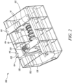
- FIG 2 is a top perspective view of the treatment apparatus 100. Some portions of the treatment apparatus 100 are shown as transparent in Figure 2 for illustrative purposes.
- the treatment apparatus 100 is used to modify the mechanical and the surface properties of the component 10 in order to prolong its useful life and/or performance.
- the treatment process for modifying the surface properties of the component 10 is vibropeening. Vibropeening is a process combining vibratory polishing and shot peening to a single polishing process in a vibratory bowl or a vibratory trough.
- the treatment apparatus 100 includes a vibratory trough 102 for receiving and retaining treatment media 12.
- the vibratory trough 102 may take a variety of forms with respect to inter alia construction, shape, and materials.
- the vibratory trough 102 has a substantially u-shaped cross-section.
- the substantially u-shaped cross-section may enable a substantially uniform flow of the treatment media 12 in a desired direction when the vibratory trough 102 is in operation. For example, this may be useful when treating pressure and suction sides of aerofoils.
- the treatment media 12 may include steel media or shot, although ceramic, metallic, polymeric, composite, or any such material of appropriate hardness, size, or shape may be used depending on the component 10 and the treatment process.
- the vibratory trough 102 may be composed of a metal, e.g., aluminium or steel, and lined with a polyurethane layer (not shown) to protect the vibratory trough 102 and avoid any chemical reaction with the construction material of the vibratory trough 102.
- the polyurethane layer may ensure a smooth flow of the treatment media 12 within the vibratory trough 102. It may also be useful to apply a layer of polyurethane to metal parts of the treatment apparatus 100 for which any polishing is not required or is undesirable. Instead of polyurethane, other materials may be used to fulfil the same or similar purpose, e.g., the vibratory trough 102 may be lined with another polymeric material.
- the treatment apparatus 100 further includes a component support 104 fixedly attached to the vibratory trough 102.
- the component support 104 may be fixedly attached to the vibratory trough 102 via fasteners, such as screws, rivets, or nut and bolts.
- the component support 104 supports the component 10 within the vibratory trough 102.
- the component support 104 is located at least partially within the vibratory trough 102.
- the component 10 is removably attached to the component support 104.
- the component support 104 may take a variety of forms so as to support the component 10 to be treated in the treatment apparatus 100.
- Figure 3A is a perspective view of the treatment apparatus 100 with some components removed.
- Figure 3B is a top view of the treatment apparatus 100 with some components removed.
- Figure 3C is a side view of the treatment apparatus 100 with some components removed.
- the component support 104 includes a support fixture 110 and a support shaft 112 attached to the support fixture 110.
- the support fixture 110 of the component support 104 is fixedly attached to the vibratory trough 102 by the fasteners.
- the support fixture 110 fixedly attaches the support shaft 112 to the vibratory trough 102 and the support shaft 112 removably mounts the component 10 within the vibratory trough 102.
- the support shaft 112 may be mounted using a bearing assembly 128 (shown in Figure 3C ).
- the support shaft 112 may be a substantially hollow shaft that spans across each end of the vibratory trough 102.
- the treatment apparatus 100 includes a pair of component supports 104 spaced apart from each other.
- the pair of component supports 104 includes respective support fixtures 110 opposing each other.
- the support shaft 112 extends at least between the support fixtures 110 of the pair of component supports 104.
- the treatment apparatus 100 further includes at least one trough wall 118 provided in the vibratory trough 102.
- the at least one trough wall 118 is configured to adjust a height, a volume, and/or a mass of the treatment media 12 in the vibratory trough 102.
- the at least one trough wall 118 includes a first trough wall 118a and an opposing second trough wall 118b provided in the vibratory trough 102.
- Each of the first and second trough walls 118a, 118b has an aperture (not shown) through which the support shaft 112 can pass.
- the first trough wall 118a is disposed proximal to one of the support fixtures 110, while the second trough wall 118b is disposed proximal to the other one of the support fixtures 110.
- the support shaft 112 passes through the component 10.
- the first trough wall 118a and the second trough wall 118b are located on the support shaft 112 on either side of the component 10 in order to support the component 10 in a desired position within the vibratory trough 102.
- the support shaft 112 may be removably locatable within the vibratory trough 102 and shaped to support the component 10 in the treatment apparatus 100.
- the component 10 includes a channel (not shown) through which the support shaft 112 may pass to support the component 10 within the vibratory trough 102 of the treatment apparatus 100.
- the support shaft 112 may include a pair of support shafts 112 and the component 10 may be supported within the vibratory trough 102 using the pair of support shafts rather than a single support shaft.
- the first trough wall 118a and the second trough wall 118b may be formed, shaped, angled and/or positioned in accordance with different application requirements.
- the treatment apparatus 100 further includes at least one trough vibrating mechanism 106 (schematically shown in Figure 1 ) that causes the vibratory trough 102 to vibrate.
- the at least one trough vibrating mechanism 106 includes suitable equipment for the vibratory trough 102 to be rocked or otherwise oscillated, as desired.
- the at least one trough vibrating mechanism 106 may include a plurality of actuators (not shown) and corresponding actuator extension rods (not shown).
- the actuator extension rods may be individually extendable, as required.
- the actuators may be powered pneumatically or hydraulically.
- the treatment apparatus 100 further includes a drive arrangement 120 configured to rotate the component 10 relative to the treatment media 12 (schematically shown in Figure 1 ).
- the drive arrangement 120 includes a motor 124, a timing belt 126 (e.g., a chain drive), and a gearbox 122 with a variable gear ratio. Therefore, the support shaft 112 is rotated by the drive arrangement 120 during the treatment process. A speed of rotation of the support shaft 112 and the component 10 may be controlled by the gearbox 122 of the drive arrangement 120 in order to control the coverage and uniformity of the treatment process (i.e., vibropeening).
- the treatment apparatus 100 further includes a treatment media inlet 130 (shown in Figure 3C ) for controllably supplying the treatment media 12 into the vibratory trough 102.
- the treatment media inlet 130 may include an inlet valve (not shown) that is in fluid communication with a reservoir (not shown) storing the treatment media 12.
- the treatment apparatus 100 further includes a treatment media outlet 132 (shown in Figure 3C ) for controllably emptying the treatment media 12 from the vibratory trough 102.
- the treatment media outlet 132 may include an outlet valve (not shown) to remove the treatment media 12 from the vibratory trough 102 after the treatment process is completed.
- the system 50 further includes a plurality of sensor devices 14 respectively and fixedly disposed at a plurality of heights relative to the vibratory trough 102. Some of the sensor devices 14 from the plurality of sensor devices 14 may be fixedly disposed at a height H1 from a base 103 of the vibratory trough 102. Some other sensor devices 14 from the plurality of sensor devices 14 may be fixedly disposed at a height H2 from the base 103 of the vibratory trough 102. Further, some other sensor devices 14 from the plurality of sensor devices 14 may be fixedly disposed at a height H3 from the base 103 of the vibratory trough 102.
- the plurality of sensor devices 14 is configured to respectively measure a plurality of movement parameters of the treatment media 12 at the plurality of heights (i.e., H1, H2, H3, and so on) and generate a plurality of movement signals 16 corresponding to the plurality of movement parameters.
- the plurality of movement parameters of the treatment media 12 may include an acceleration and/or a speed of the treatment media 12 at the plurality of heights.
- the plurality of movement parameters may be a plurality of vibration parameters. Therefore, the plurality of movement signals 16 may be a plurality of vibration signals.
- each of the plurality of sensor devices 14 is fixedly attached to the support fixture 110.
- each of the plurality of sensor devices 14 may measure a relative movement parameter of the treatment media 12 with respect to the vibratory trough 102 at a corresponding height from the plurality of heights.
- each of the plurality of sensor devices 14 may include an intensity prediction unit, a vibration monitoring sensor, an accelerometer, an ultrasonic senor, an infrared sensor, and/or any other sensor capable of measuring the plurality of movement parameters of the treatment media 12 at the plurality of heights.
- the system 50 further includes a central controller 18 communicably coupled to each of the plurality of sensor devices 14.
- the central controller 18 may be a control circuit, a computer, a microprocessor, a microcomputer, a central processing unit, or any suitable device or apparatus.
- the central controller 18 may include one or more of a digital processor, an analog processor, a digital circuit designed to process information, an analog circuit designed to process information, a state machine, and/or other mechanisms for electronically processing information.
- the central controller 18 is communicably coupled to each of the plurality of sensor devices 14 via at least one of a wired connection and a wireless connection. Functional details of the central controller 18 will be described later in the description.
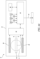
- FIG. 4A is a detailed schematic view of a sensor device 14 from the plurality of sensor devices 14.
- each of the plurality of sensor devices 14 includes a casing 42 (e.g., a metal housing).
- the casing 42 may be a cuboidal casing.
- each of the plurality of sensor devices 14 further includes at least two fixed electrodes 28 for generating an electric field F. Further, an electric parameter (e.g., an electric current, an electric voltage, etc.) is applied across the at least two fixed electrodes 28 to induce the electric field F between the at least two fixed electrodes 28.
- an electric parameter e.g., an electric current, an electric voltage, etc.
- Each of the plurality of sensor devices 14 further includes at least one movable electrode 30 disposed between the at least two fixed electrodes 28.
- the at least one movable electrode 30 moves causing the electric field F between the at least two fixed electrodes 28 to change.
- each of the plurality of sensor devices 14 further includes an electric circuit 32 electrically coupled to the at least two fixed electrodes 28 and the at least one movable electrode 30.
- the electric circuit 32 is configured to measure the corresponding movement parameter based on the change in the electric field F between the at least two fixed electrodes 28.
- each of the plurality of sensor devices 14 further includes a processor 34 communicably coupled to the electric circuit 32.
- the processor 34 is configured to generate the corresponding movement signal 16 based on the corresponding movement parameter.
- the processor 34 is further configured to transmit the corresponding movement signal 16 to the central controller 18.
- each of the plurality of sensor devices 14 further includes a data storage unit 38 configured to store the plurality of movement signals 16 and a set of instructions or a genetic algorithm that is executable by the processor 34.
- each of the plurality of sensor devices 14 further includes a communication unit 35 to transfer data in real-time to an external unit or to connect to an external digital device.
- the communication unit 35 of each of the plurality of sensor devices 14 may transfer the corresponding movement signal 16 to the central controller 18.
- the communication unit 35 may be a Wi-Fi or Bluetooth unit.
- each of the plurality of sensor devices 14 further includes a power supply circuit 36 that enables charging of a battery of the corresponding sensor device 14.
- each of the plurality of sensor devices 14 further includes a receiver 39 that may receive data from the central controller 18. In some cases, the receiver 39 may receive data (e.g., the plurality of movement parameters) from other sensors from the plurality of sensors 14. In some embodiments, each of the plurality of sensor devices 14 further includes a digital display 40. In some embodiments, the digital display 40 is communicably coupled to the processor 34 and configured to display the corresponding movement signal 16. In some embodiments, the digital display 40 is communicably coupled to the receiver 39 and configured to display one or more values corresponding to the received data to a user. The receiver 39 includes a digital display 40 to display the values corresponding to the received data. In some embodiments, each of the plurality of sensor devices 14 further includes a user input interface 41 (e.g., one or more buttons) to configure one or more settings of the sensor device 14 or the digital display 40 of the sensor device 14.
- a user input interface 41 e.g., one or more buttons
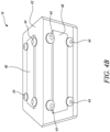
- Figure 4B is a perspective view (i.e., outer view) of a sensor device 14 from the plurality of sensor devices 14.
- the casing 42 of each of the plurality of sensor devices 14 includes one or more provisions/devices 44 for removably attaching a test strip 46 to the casing 42.
- the test strip 46 may be a metal or alloy strip of a predetermined thickness to determine an intensity of the treatment process being induced on the component 10.
- the test strip may include Almen test strip (thin strip of SAE 1070 steel) used to quantify the intensity of the vibropeening of the component 10 (shown in Figures 1 and 2 ).
- the intensity of the treatment process may correspond to an arc height of Almen test strip measured at a coverage of 98% using an Almen gauge.
- the provisions 44 may include fasteners for removably holding the test strip 46 on the casing 42.
- the provisions 44 may include mechanisms, latching mechanisms, or any other suitable attachment mechanisms capable of removably attaching the test strip 46 to the casing 42.
- the central controller 18 is configured to receive the plurality of movement signals 16 from the plurality of sensor devices 14.
- the central controller 18 is further configured to determine a plurality of process variables 20 corresponding to the plurality of movement signals 16.
- the plurality of process variables 20 may include values of energy, coverage, and intensity of the treatment process.
- the system 50 further includes a display device 108 (shown in Figure 1 ) communicably coupled to the central controller 18.
- the display device 108 is configured to display the plurality of process variables 20.
- the display device 108 may display the energy, the intensity, and/or coverage of the treatment process at the plurality of heights.
- an operator may also adjust or control the treatment apparatus 100 based on the plurality of process variables 20 displayed on the display device 108.
- the display device 108 may be a monitor or a screen.
- the central controller 18 is further configured to control the treatment apparatus 100 based at least on the plurality of process variables 20. In some embodiments, the central controller 18 is further configured to control the at least one trough vibrating mechanism 106 (shown in Figure 1 ) of the treatment apparatus 100 based on the plurality of process variables 20. In other words, the central controller 18 may control the at least one trough vibrating mechanism 106 so as to adjust the amount of vibration of the vibratory trough 102. For example, the central controller 18 may control one or more of the plurality of actuators and corresponding actuator extension rods.
- the central controller 18 is further configured to control the drive arrangement 120 (shown in Figure 2 ) of the treatment apparatus 100 based on the plurality of process variables 20. For example, according to desired application requirements, the central controller 18 may adjust a speed of rotation of the support shaft 112 and thereby, the rotation of the component 10 by controlling the gearbox 122 of the drive arrangement 120. In some embodiments, the central controller 18 is further configured to control the at least one trough wall 118 (shown in Figure 3A ) of the treatment apparatus 100 based on the plurality of process variables 20.
- the central controller 18 may adjust the height, the volume, and/or the mass of the treatment media 12 in the vibratory trough 102 by controlling the first trough wall 118a and the second trough wall 118b.
- the central controller 18 is further configured to control the treatment media inlet 130 and/or the treatment media outlet 132 (shown in Figure 3C ) of the treatment apparatus 100 based on the plurality of process variables 20 to further adjust the height, the volume and/or the mass of the treatment media 12 in the vibratory trough 102.
- the central controller 18 is further configured to receive a predetermined process parameter 22 (shown in Figure 1 ) for the treatment process.
- the predetermined process parameter 22 may be a drawing requirement of the treatment process for the component 10.
- the predetermined process parameter 22 may be manually provided by the user via one or more input devices (not shown).
- the predetermined process parameter 22 may be retrieved from a memory (not shown) communicably coupled to the central controller 18.
- the central controller 18 may include the memory.
- the memory may include an external database or a library.
- the central controller 18 is further configured to determine a measured process parameter 24 (shown in Figure 1 ) based on the plurality of process variables 20.
- the measured process parameter 24 may be an overall intensity of the treatment process which may be determined by the central controller 18 using the plurality of process variables 20 (e.g., a plurality of intensities) measured at the plurality of heights.
- the central controller 18 is further configured to control the treatment apparatus 100 based on the predetermined process parameter 22 and the measured process parameter 24, such that a difference between the predetermined process parameter 22 and the measured process parameter 24 is reduced.
- desirable intensity and/or energy e.g., the predetermined process parameter 22 of the treatment process (i.e., vibropeening) may be obtained.
- the central controller 18 is further configured to, prior to receiving the plurality of movement signals 16 from the plurality of sensor devices 14, determine a plurality of predicted process variables 26 corresponding to the plurality of heights of the vibratory trough 102.
- the plurality of predicted process variables 26 may be predicted intensities of the treatment process (i.e., vibropeening) at the plurality of heights.
- the plurality of predicted process variables 26 may be predicted based on one or more machine-learning models and/or algorithms.
- the central controller 18 is further configured to control the treatment apparatus 100 based on the plurality of predicted process variables 26 and the plurality of process variables 20, such that a difference between each of the plurality of process variables 20 and a corresponding predicted process variable 26 from the plurality of predicted process variables 26 is reduced.
- desirable value of intensity and/or energy of the treatment process i.e., vibropeening
- H1, H2, H3, and so on as shown in Figure 1 .
- the central controller 18 controls the treatment apparatus 100 based at least on the plurality of process variables 20, such as a value of the energy, the coverage, and/or the intensity at the respective heights (i.e., H1, H2, H3, and so on) relative to the vibratory trough 102.
- the central controller 18 communicably coupled to the plurality of sensor devices 14 fixedly disposed at the plurality of heights relative to the vibratory trough 102 may enable the system 50 to monitor the plurality of movement signals 16 and the plurality of process variables 20 in specific sections of the vibratory trough 102.
- the system 50 may be used to obtain a desired parameter of the treatment process (i.e., vibropeening) for a specific aerospace component according to the drawing requirement.
- the central controller 18 and the plurality of sensor devices 14 may validate a process control method and/or mechanism for the treatment process for the component 10.
- the system 50 may substantially reduce human intervention because of continuous determination of the plurality of process variables 20 corresponding to the plurality of movement signals 16 and subsequently controlling the treatment apparatus 100 based at least on the plurality of process variables 20.
- the system 50 may enable the vibropeening which is relatively faster with less intensive manual labour. Further, in the system 50, there are minimal chances of wastage of sacrificial Almen strips or scrapping of components which may not meet the drawing requirements.
- the system 50 may be used for vibropeening of rotationally symmetric as well as asymmetric components.
- Figure 5A is a perspective view of a system 50' for controlling the treatment process that modifies surface properties of the component 10, according to an embodiment of the present invention.
- the system 50' is substantially similar and functionally equivalent to the system 50 of Figure 1 , with common components being referred to by the same numerals. Some portions of the treatment apparatus 100 are shown as transparent in Figure 5A for illustrative purposes. Some of the components are not shown in Figure 5A for illustrative purposes. However, in the illustrated embodiment of Figure 5A , the system 50' further includes a frame 114 fixedly attached to the vibratory trough 102.
- Figure 5B is a perspective view of the frame 114. Functional advantages of the system 50' is the same as that of the system 50 of Figure 1 .
- the frame 114 includes one or more vertical hangers 116. Each of the one or more vertical hangers 116 extends at least partially into the treatment media 12. In the illustrated embodiment of Figures 5A and 5B , a total of four vertical hangers 116 are shown. However, in other embodiments, the frame 114 may include any number of the vertical hangers 116. Each of the plurality of sensor devices 14 is fixedly attached to the one or more vertical hangers 116 of the frame 114. In the illustrated embodiment of Figures 5A and 5B , a total of three sensor devices 14 are fixedly attached to each vertical hanger 116. In other embodiments, any number of sensor devices 14 may be fixedly attached to each vertical hanger 116, as per application requirements.
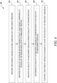
- Figure 6 is a flowchart illustrating a method 200 for controlling the treatment process that modifies the surface properties of the component 10 (shown in Figures 1 and 2 ), according to an embodiment of the present invention.
- the method 200 includes providing the treatment apparatus 100 (shown in Figures 1 and 2 ) for carrying out the treatment process.
- the method 200 includes providing the plurality of sensor devices 14 (shown in Figures 1 and 2 ) respectively and fixedly disposed at the plurality of heights (i.e., H1, H2, H3, and so on, shown in Figure 1 ) relative to the vibratory trough 102.
- the method 200 includes receiving the plurality of movement signals 16 (shown in Figure 1 ) from the plurality of sensor devices 14.
- the method 200 includes determining the plurality of process variables 20 (shown in Figure 1 ) corresponding to the plurality of movement signals 16.
- the method 200 includes controlling the treatment apparatus 100 based at least on the plurality of process variables 20.
- the central controller 18 may include a memory (not shown) storing computer executable instructions or computer code that may be executed by the central controller 18 to perform the step 210 of the method 200.
- controlling the treatment apparatus 100 further includes controlling the at least one trough vibrating mechanism 106 based on the plurality of process variables 20.
- the central controller 18 may control one or more of the plurality of actuators and the corresponding actuator extension rods of the treatment apparatus 100 based at least on the plurality of process variables 20 to adjust the amount of vibration of the vibratory trough 102.
- controlling the treatment apparatus 100 further includes adjusting the height, volume, and/or mass of the treatment media 12 in the vibratory trough 102 based on the plurality of process variables 20.
- controlling the treatment apparatus 100 further includes controlling a rotation of the component 10 relative to the treatment media 12 based on the plurality of process variables 20.
- the central controller 18 may adjust a speed of rotation of the support shaft 112 and thereby, the rotation of the component 10 by controlling the gearbox 122 of the drive arrangement 120.
- controlling the treatment apparatus 100 further includes controllably supplying the treatment media 12 into the vibratory trough 102 and/or controllably emptying of the treatment media 12 from the vibratory trough 102 based on the plurality of process variables 20.
- the central controller 18 may control the treatment media inlet 130 and/or the treatment media outlet 132 of the treatment apparatus 100 based at least on the plurality of process variables 20 to adjust the height, volume, and/or mass of the treatment media 12 in the vibratory trough 102.
- the method 200 further includes receiving the predetermined process parameter 22 (shown in Figure 1 ) of the treatment process.
- the method 200 further includes determining the measured process parameter 24 (shown in Figure 1 ) based on the plurality of process variables 20.
- controlling the treatment apparatus 100 further includes controlling the treatment apparatus 100 based on the predetermined process parameter 22 and the measured process parameter 24, such that the difference between the predetermined process parameter 22 and the measured process parameter 24 is reduced.
- the method 200 further includes, prior to receiving the plurality of movement signals 16 from the plurality of sensor devices 14, determining the plurality of predicted process variables 26 (shown in Figure 1 ) corresponding to the plurality of heights of the vibratory trough 102.
- controlling the treatment apparatus 100 further includes controlling the treatment apparatus 100 based on the plurality of predicted process variables 26 and the plurality of process variables 20, such that the difference between each of the plurality of process variables 20 and the corresponding predicted process variable 26 from the plurality of predicted process variables 26 is reduced.
Landscapes
- Engineering & Computer Science (AREA)
- Mechanical Engineering (AREA)
- Jigging Conveyors (AREA)
- Finish Polishing, Edge Sharpening, And Grinding By Specific Grinding Devices (AREA)
Abstract
Description
- The present invention relates to a system and a method for controlling a treatment process that modifies surface properties of a component.
- Mechanical articles typically degrade in various ways over time especially when operated for long durations of time in extremes of temperature. The degradation often primarily or at least initially tends to occur at one or more surfaces of the articles concerned. It is known in the aerospace industry to treat the surface of components, especially gas turbine components, such as compressor blades, turbine blades, and bladed integrated disks, in order to modify/enhance the performance/life and/or appearance of those components.
- It is well known that polishing a metal surface can improve its appearance. It involves rubbing the surface and/or applying a chemical substance to it to make the surface smooth and shiny. Vibropolishing, aka ball pressure polishing, is a polishing method that involves placing an article in a container of specially shaped pellets and vibrating the container so that the pellets rub against the article to deburr, radius, descale, burnish, clean, and/or brighten its surface. While vibropolishing is useful for improving the surface roughness of aerospace components it can undesirably remove material and detrimentally affect aerofoil geometries.
- The process of working on a metal surface to improve its material properties is known as peening. Certain types of peening reflect the manner in which the metal surface is worked upon. Peening is not restricted to metal surfaces. It is, for example, possible to peen composite materials. Shot peening is a cold working process that involves striking the surface of a metal or a composite with a shot with sufficient force to produce a compressive residual stress layer by plastic deformation. The shot can, for example, be in the form of round metallic, glass, or ceramic particles. The process is intended to modify the mechanical properties of the metal or the composite without removing any appreciable material. It is known to use shot peening to strengthen car crankshafts and connecting rods. While shot peening is useful for providing desired compressive residual stresses in aerospace components, it typically undesirably increases surface roughness.
- Vibropeening is a process that combines vibratory polishing and shot peening to a single polishing process in a vibratory bowl/trough. Also known as ball polishing, it is known to be useful for improving the appearance of car wheels, various types of furniture, and cutlery.
- Tests have shown that vibro-treating, i.e., vibropeening or vibropolishing, a component of a gas turbine engine (e.g., a bladed disk drum and a fan blade) results in a non-uniform residual stress distribution and material properties across the length due to asymmetry of the component. This may undesirably increase treatment time and process cost.
- However, currently there is no validated process control mechanism for vibropeening. This may be because vibropeening is a low energy process and may therefore take significant amount of time to perform process control checks thereby reducing the business case benefit introduced through elimination of shot peening. Further, if a drawing parameter (e.g., a process intensity) for a component is not as per drawing requirement after quantification using Almen strips, then significant time may be again required to revalidate a vibropeening setup to be deemed as fit for obtaining the drawing parameter as per the drawing requirement for the component. Further, if the drawing parameter for the component is not as per drawing requirement after quantification, the component may have to be discarded. Moreover, in conventional vibropeening techniques, human intervention is relatively high as measuring Almen intensity through saturation curves is a very labour-intensive process. Also, conventional vibropeening techniques may cause an excessive amount of cost to be spent on the sacrificial Almen strips in a production plant. Therefore, there exists a need for a system and a method that control such a treatment process in an improved/sustainable manner.
- The present invention provides a method and a system for controlling a treatment process that modifies surface properties of a component that addresses the shortcomings of conventional polishing and peening methods, or at least provides a useful alternative to the same.
- According to a first aspect there is provided a system for controlling a treatment process that modifies surface properties of a component. The system includes a treatment apparatus for carrying out the treatment process. The treatment apparatus includes a vibratory trough for receiving and retaining treatment media. The treatment apparatus further includes a component support fixedly attached to the vibratory trough. The component support supports the component within the vibratory trough. The treatment apparatus further includes at least one trough vibrating mechanism that causes the vibratory trough to vibrate. The system further includes a plurality of sensor devices respectively and fixedly disposed at a plurality of heights relative to the vibratory trough. The plurality of sensor devices is configured to respectively measure a plurality of movement/vibration parameters of the treatment media at the plurality of heights and generate a plurality of movement/vibration signals corresponding to the plurality of movement/vibration parameters. The vibration parameters may be defined by the oscillating, reciprocating, or any other periodic motion of a rigid or elastic body or medium forced from a position or state of equilibrium. The movement may be timely adjusted according to requirements, for e.g., primarily introduce high residual compressive stresses by other parameters and secondary treatment to smoothen the surface roughness which might both not be periodically. The system further includes a central controller communicably coupled to each of the plurality of sensor devices. The central controller is configured to receive the plurality of movement signals from the plurality of sensor devices. The central controller is further configured to determine a plurality of process variables corresponding to the plurality of movement signals. The central controller is further configured to control the treatment apparatus based at least on the plurality of process variables.
- The central controller controls the treatment apparatus based at least on the plurality of process variables, such as a value of an energy/impulse, a coverage, and/or an intensity at respective heights relative to the vibratory trough. The central controller communicably coupled to the plurality of sensor devices fixedly disposed at the plurality of heights relative to the vibratory trough may enable the system of the present invention to monitor the plurality of movement signals and the plurality of process variables. In other words, the system of the present invention may be used to obtain a desired parameter of the treatment process (i.e., vibropeening) for a specific aerospace component according to the drawing requirement.
- As the controller controls the treatment apparatus based at least on the plurality of process variables corresponding to the plurality of movement signals, the system of the present invention may provide uniform residual stress distribution and material properties across the component during the treatment process (i.e., vibropeening). This may improve fatigue life and/or performance of the component. This is particularly important when the component is large in size. Further, unlike conventional techniques where the component may have to be scrapped if there is any error in obtaining the drawing requirement (e.g., Almen intensity), the system of the present invention may enable monitoring the vibropeening at specific heights and accordingly controlling the vibropeening of the component. As a result, a likelihood of scrapping the component after the treatment process of the component may be reduced by the system of the present invention. Therefore, the central controller and the plurality of sensor devices may validate a process control method and/or mechanism of the treatment process for the component.
- Moreover, as compared to the conventional vibropeening techniques, the system of the present invention may substantially reduce human intervention because of continuous determination of the plurality of process variables corresponding to the plurality of movement signals and subsequently controlling the treatment apparatus based at least on the plurality of process variables. The system of the present invention may enable the vibropeening which is relatively faster with less intensive manual labour which may significantly reduce developmental time and cost for research. This will enable faster optimization of the process to meet a specific drawing requirement for any given component/geometry at a specific location. Such a method also could be used for locally optimizing vibropeening for specific repair process through various fixturing/masking steps. Further, in the proposed system, there are minimal chances of wastage of sacrificial Almen strips or scrapping of components which may not meet the drawing requirements. The system of the present invention may be used for vibropeening of rotationally symmetric as well as asymmetric components.
- In some embodiments, the system further includes a display device communicably coupled to the central controller. The display device is configured to display the plurality of process variables. The display device may display intensity of the treatment process. In some applications, an operator may also adjust or control the treatment apparatus based on the plurality of process variables displayed on the display device. The display device may be a monitor or a screen.
- In some embodiments, the component support includes a support fixture and a support shaft attached to the support fixture. The support fixture fixedly attaches the support shaft to the vibratory trough and the support shaft removably mounts the component within the vibratory trough. Each of the plurality of sensor devices is fixedly attached to the support fixture. The support shaft may be mounted using a bearing assembly. The support shaft may be a substantially hollow shaft that spans across each end of the vibratory trough. The support shaft may be removably locatable within the vibratory trough and shaped to support the component to be treated in the treatment apparatus.
- In some embodiments, the system further includes a frame fixedly attached to the vibratory trough. The frame further includes one or more vertical hangers. Each of the plurality of sensor devices is fixedly attached to the one or more vertical hangers of the frame. The frame may also include a plurality of holders attached to the one or more vertical hangers and configured to receive the respective plurality of sensor devices. The one or more vertical hangers may allow mounting of the plurality of sensor devices at the respective plurality of heights relative to the vibratory trough.
- In some embodiments, each of the one or more vertical hangers extends at least partially into the treatment media. When each of the one or more vertical hangers extends at least partially into the treatment media, the plurality of sensor devices may respectively measure the plurality of movement parameters of the treatment media at the plurality of heights and generate the plurality of movement signals corresponding to the plurality of movement parameters.
- In some embodiments, the central controller is further configured to receive a predetermined process parameter for the treatment process. The central controller is further configured to determine a measured process parameter based on the plurality of process variables. The central controller is further configured to control the treatment apparatus based on the predetermined process parameter and the measured process parameter, such that a difference between the predetermined process parameter and the measured process parameter is reduced. By reducing the difference between the predetermined process parameter and the measured process parameter, a desirable intensity and/or energy of the treatment process (i.e., vibropeening) may be obtained at the plurality of heights. The measured process parameter may be an overall intensity of the treatment process. The predetermined process parameter may be the drawing requirement.
- In some embodiments, the central controller is further configured to, prior to receiving the plurality of movement signals from the plurality of sensor devices, determine a plurality of predicted process variables corresponding to the plurality of heights of the vibratory trough. The central controller is further configured to control the treatment apparatus based on the plurality of predicted process variables and the plurality of process variables, such that a difference between each of the plurality of process variables and a corresponding predicted process variable from the plurality of predicted process variables is reduced. By reducing the difference between each of the plurality of process variables and the corresponding predicted process variable from the plurality of predicted process variables, a desirable value of intensity and/or energy of the treatment process (i.e., vibropeening) may be obtained at the plurality of heights. The plurality of predicted process variables may be predicted intensities of the treatment process at the plurality of heights.
- In some embodiments, the central controller is further configured to control the at least one trough vibrating mechanism of the treatment apparatus based on the plurality of process variables. Therefore, the central controller may adjust the vibration of the vibratory trough based on the plurality of process variables, such as a value of an energy, a coverage, and/ or an intensity of the treatment process.
- In some embodiments, the treatment apparatus further includes at least one trough wall provided in the vibratory trough and configured to adjust a height, a volume, and/or a mass of the treatment media in the vibratory trough. The central controller is further configured to control the at least one trough wall of the treatment apparatus based on the plurality of process variables. By adjusting the height, the volume, and/or the mass of the treatment media in the vibratory trough, various characteristics and the overall intensity of the treatment process may be varied as per desirable application attributes. The trough wall may include a slot to receive the support shaft at various heights depending on application requirements.
- In some embodiments, the treatment apparatus further includes a drive arrangement configured to rotate the component relative to the treatment media. The central controller is further configured to control the drive arrangement of the treatment apparatus based on the plurality of process variables. The drive arrangement may include a motor, a timing belt, and a gearbox with a variable gear ratio. The central controller may adjust a speed of the motor based on the plurality of process variables in order to control the coverage and uniformity of the treatment process (i.e., vibropeening).
- In some embodiments, the treatment apparatus further includes a treatment media inlet for controllably supplying the treatment media into the vibratory trough and a treatment media outlet for controllably emptying the treatment media from the vibratory trough. The central controller is further configured to control the treatment media inlet and/or the treatment media outlet of the treatment apparatus based on the plurality of process variables. The treatment media inlet may be an inlet valve and the treatment media outlet may be an outlet valve. The treatment media inlet and the treatment media outlet may also be used to keep a desirable volume, height, and/or mass of the treatment media in the vibratory trough.
- In some embodiments, each of the plurality of sensor devices includes at least two fixed electrodes for generating an electric field. An electric parameter is applied across the at least two fixed electrodes to induce the electric field between the at least two fixed electrodes. Each of the plurality of sensor devices further includes at least one movable electrode disposed between the at least two fixed electrodes. Upon vibration of the vibratory trough, the at least one movable electrode moves causing the electric field between the at least two fixed electrodes to change. Each of the plurality of sensor devices further includes an electric circuit electrically coupled to the at least two fixed electrodes and the at least one movable electrode. The electric circuit is configured to measure the corresponding movement parameter based on the change in the electric field between the at least two fixed electrodes. Each of the plurality of sensor devices further includes a processor communicably coupled to the electric circuit. The processor is configured to generate the corresponding movement signal based on the corresponding movement parameter. The processor is further configured to transmit the corresponding movement signal to the central controller. Therefore, the plurality of sensor devices generates the plurality of movement signals corresponding to the plurality of movement parameters. In other words, upon movement of the at least one movable electrode by vibration of the vibratory trough, the electric circuit measures the corresponding movement parameter (e.g., acceleration of the treatment media in the vibratory trough) based on the change in the electric field between the at least two fixed electrodes.
- In some embodiments, each of the plurality of sensor devices further includes a casing. The casing includes one or more provisions for removably attaching a test strip to the casing. The test strip may be an Almen test strip that is used to quantify the intensity of the treatment process (i.e., vibropeening). The test strip may be a metal/alloy strip of a predetermined thickness to monitor the intensity of the treatment process being induced on the component.
- According to a second aspect there is provided a method for controlling a treatment process that modifies surface properties of a component. The method includes providing a treatment apparatus for carrying out the treatment process. The treatment apparatus includes a vibratory trough for receiving and retaining treatment media. The treatment apparatus further includes a component support fixedly attached to the vibratory trough. The component support supports the component within the vibratory trough. The treatment apparatus further includes at least one trough vibrating mechanism that causes the vibratory trough to vibrate. The method further includes providing a plurality of sensor devices respectively and fixedly disposed at a plurality of heights relative to the vibratory trough. The plurality of sensor devices is configured to respectively measure a plurality of movement/vibration parameters of the treatment media at the plurality of heights and generate a plurality of movement/vibration signals corresponding to the plurality of movement parameters. The method further includes receiving the plurality of movement signals from the plurality of sensor devices. The method further includes determining a plurality of process variables corresponding to the plurality of movement signals. The method further includes controlling the treatment apparatus based at least on the plurality of process variables.
- In some embodiments, the method further includes receiving a predetermined process parameter of the treatment process. The method further includes determining a measured process parameter based on the plurality of process variables. Controlling the treatment apparatus further includes controlling the treatment apparatus based on the predetermined process parameter and the measured process parameter, such that a difference between the predetermined process parameter and the measured process parameter is reduced.
- In some embodiments, the method further includes, prior to receiving the plurality of movement signals from the plurality of sensor devices, determining a plurality of predicted process variables corresponding to the plurality of heights of the vibratory trough. Controlling the treatment apparatus further includes controlling the treatment apparatus based on the plurality of predicted process variables and the plurality of process variables, such that a difference between each of the plurality of process variables and a corresponding predicted process variable from the plurality of predicted process variables is reduced.
- In some embodiments, controlling the treatment apparatus further includes controlling the at least one trough vibrating mechanism based on the plurality of process variables.
- In some embodiments, controlling the treatment apparatus further includes adjusting a height, a volume, and/or a mass of the treatment media in the vibratory trough based on the plurality of process variables.
- In some embodiments, controlling the treatment apparatus further includes controlling a rotation of the component relative to the treatment media based on the plurality of process variables.
- In some embodiments, controlling the treatment apparatus further includes controllably supplying the treatment media into the vibratory trough and/or controllably emptying of the treatment media from the vibratory trough based on the plurality of process variables.
- In some embodiments, the component is a gas turbine engine component.
- In some embodiments, the gas turbine engine component is a bladed disk drum, compressor airfoils made of conventional/ additive manufacture methods or a fan blade.
- The term "shot peening", as used herein, is a method of modifying the mechanical properties of an article that involves striking the surface of the article, typically made of metal or composite, with shot with sufficient force to produce a compressive residual stress layer in the article by plastic deformation. The method tends to result in the article having a rough surface.
- The term "vibrofinishing" (aka vibratory finishing), as used herein, is a method for polishing the surface of an article, typically made of metal or composite, which involves vibrating the article amongst certain specially shaped pellets to decrease the surface roughness of the article. Shot peened articles are often vibrofinished to reduce their surface roughness, with the vibrofinishing typically removing some material from the article but typically not affecting the residual stress created during the shot peening process. It is typically advisable to minimise any vibropolishing in order to minimise the removal of material. Indeed excessive vibropolishing shot peened articles can remove the compressive residual stress layer formed by the shot peening.
- The term "vibropeening" (aka vibratory peening), as used herein, is a method of modifying the mechanical and surface properties of an article, typically made of metal of composite, that involves vibrating the article within a treatment media to polish the article, reduce its surface roughness, and to induce compressive residual stress on the article. Vibropeening tends to provide a superior surface finish to shot peening. It also tends to provide a deeper layer of compression than shot peening albeit typically providing somewhat less residual stress than shot peening.
- The term "fatigue life", as used herein, means the time by which a component or material will last before completely failing because of concentrated stresses.
- Throughout this specification and in the claims that follow, unless the context requires otherwise, the word "comprise" or variations such as "comprises" and "comprising", will be understood to imply the inclusion of a stated integer or group of integers but not the exclusion of any other stated integer or group of integers.
- The skilled person will appreciate that except where mutually exclusive, a feature or parameter described in relation to any one of the above aspects may be applied to any other aspect. Furthermore, except where mutually exclusive, any feature or parameter described herein may be applied to any aspect and/or combined with any other feature or parameter described herein.
- Embodiments will now be described by way of example only, with reference to the Figures, in which:
-
Figure 1 is a schematic diagram of a system for controlling a treatment process that modifies surface properties of a component, according to a first embodiment of the present invention; -
Figure 2 is a top perspective view of a treatment apparatus of the system ofFigure 1 ; -
Figure 3A is a perspective view of the treatment apparatus with some components removed; -
Figure 3B is a top view of the treatment apparatus; -
Figure 3C is a front view of the treatment apparatus; -
Figure 4A is a detailed schematic view of a sensor device from a plurality of sensor devices of the system ofFigure 1 ; -
Figure 4B is a perspective view of a sensor device from the plurality of sensor devices ofFigure 4A ; -
Figure 5A is a perspective view of a system for controlling a treatment process that modifies surface properties of a component, according to a second embodiment of the present invention; -
Figure 5B is a perspective view of a frame of the system ofFigure 5A ; and -
Figure 6 is a flowchart illustrating a method for controlling the treatment process that modifies the surface properties of the component. - The following table lists the reference numerals used in the drawings with the features to which they refer:
Ref no. Feature Figure 10 Component 1 2 3A 3B 3C 5A 12 Treatment media 1 14 Sensor device(s) 1 2 3A 3C 4A 4B 5A 5B 16 Movement signal(s) 1 4A 5A 18 Central controller 1 4A 5A 20 Process variables 1 5A 22 Predetermined process parameter 1 24 Measured process parameter 1 5A 26 Predicted process variables 1 5A 28 Fixed electrode(s) 4A 30 Movable electrode 4A 32 Electric circuit 4A 34 Processor 4A 35 Communication unit 4A 36 Power supply circuit 4A 38 Data storage unit 4A 39 Receiver 4A 40 Digital display 4A 41 User input interface 4A 42 Casing 4A 4B 44 Provision for removably attaching a test strip to the casing 4B 46 Test strip 4B 50 System 1 50' System 5A 100 Treatment apparatus 1 2 3A 3B 3C 5A 102 Vibratory trough 1 2 5A 103 Base 1 104 Component support 1 2 3A 3B 3C 5A 106 Trough vibrating mechanism 1 108 Display device 5A 110 Support fixture 1 2 3A 3B 3C 5A 112 Support shaft 1 2 3A 3B 3C 5A 114 Frame 5A 5B 116 Vertical hanger(s) 5A 5B 118 Trough wall 3A 118a First trough wall 3A 118b Second trough wall 3A 120 Drive arrangement 2 3A 3B 3C 5A 122 Gearbox 2 3A 3B 3C 5A 124 Motor 2 3B 3C 5A 126 Timing belt 2 3A 3C 5A 128 Bearing assembly 3C 130 Treatment media inlet 3C 132 Treatment media outlet 3C 200 Method 6 202 Step 6 204 Step 6 206 Step 6 208 Step 6 210 Step 6 F Electric field 4A H1 Height 1 H2 Height 1 H3 Height 1 - Aspects and embodiments of the present invention will now be discussed with reference to the accompanying figures. Further aspects and embodiments will be apparent to those skilled in the art.
-
Figure 1 is a schematic diagram of asystem 50 for controlling a treatment process that modifies surface properties of acomponent 10, according to an embodiment of the present invention. In some embodiments, the treatment process modifies mechanical properties of thecomponent 10. In some embodiments, thecomponent 10 is a part of a gas turbine engine (not shown). In some embodiments, thecomponent 10 of the gas turbine engine is a bladed disk drum or a fan blade. Thesystem 50 includes atreatment apparatus 100 for carrying out the treatment process. -
Figure 2 is a top perspective view of thetreatment apparatus 100. Some portions of thetreatment apparatus 100 are shown as transparent inFigure 2 for illustrative purposes. Thetreatment apparatus 100 is used to modify the mechanical and the surface properties of thecomponent 10 in order to prolong its useful life and/or performance. In some embodiments, the treatment process for modifying the surface properties of thecomponent 10 is vibropeening. Vibropeening is a process combining vibratory polishing and shot peening to a single polishing process in a vibratory bowl or a vibratory trough. - Referring to
Figures 1 and2 , thetreatment apparatus 100 includes avibratory trough 102 for receiving and retainingtreatment media 12. Thevibratory trough 102 may take a variety of forms with respect to inter alia construction, shape, and materials. In the illustrated embodiment ofFigure 2 , thevibratory trough 102 has a substantially u-shaped cross-section. The substantially u-shaped cross-section may enable a substantially uniform flow of thetreatment media 12 in a desired direction when thevibratory trough 102 is in operation. For example, this may be useful when treating pressure and suction sides of aerofoils. Thetreatment media 12 may include steel media or shot, although ceramic, metallic, polymeric, composite, or any such material of appropriate hardness, size, or shape may be used depending on thecomponent 10 and the treatment process. - In some embodiments, the
vibratory trough 102 may be composed of a metal, e.g., aluminium or steel, and lined with a polyurethane layer (not shown) to protect thevibratory trough 102 and avoid any chemical reaction with the construction material of thevibratory trough 102. The polyurethane layer may ensure a smooth flow of thetreatment media 12 within thevibratory trough 102. It may also be useful to apply a layer of polyurethane to metal parts of thetreatment apparatus 100 for which any polishing is not required or is undesirable. Instead of polyurethane, other materials may be used to fulfil the same or similar purpose, e.g., thevibratory trough 102 may be lined with another polymeric material. - The
treatment apparatus 100 further includes acomponent support 104 fixedly attached to thevibratory trough 102. In some embodiments, thecomponent support 104 may be fixedly attached to thevibratory trough 102 via fasteners, such as screws, rivets, or nut and bolts. Thecomponent support 104 supports thecomponent 10 within thevibratory trough 102. Thecomponent support 104 is located at least partially within thevibratory trough 102. Thecomponent 10 is removably attached to thecomponent support 104. Thecomponent support 104 may take a variety of forms so as to support thecomponent 10 to be treated in thetreatment apparatus 100. -
Figure 3A is a perspective view of thetreatment apparatus 100 with some components removed.Figure 3B is a top view of thetreatment apparatus 100 with some components removed.Figure 3C is a side view of thetreatment apparatus 100 with some components removed. Referring toFigures 1 to 3C , in some embodiments, thecomponent support 104 includes asupport fixture 110 and asupport shaft 112 attached to thesupport fixture 110. In some embodiments, thesupport fixture 110 of thecomponent support 104 is fixedly attached to thevibratory trough 102 by the fasteners. Thesupport fixture 110 fixedly attaches thesupport shaft 112 to thevibratory trough 102 and thesupport shaft 112 removably mounts thecomponent 10 within thevibratory trough 102. Thesupport shaft 112 may be mounted using a bearing assembly 128 (shown inFigure 3C ). In some embodiments, thesupport shaft 112 may be a substantially hollow shaft that spans across each end of thevibratory trough 102. - In the illustrated embodiment of
FIGS. 1 to 3C , thetreatment apparatus 100 includes a pair of component supports 104 spaced apart from each other. The pair of component supports 104 includesrespective support fixtures 110 opposing each other. Thesupport shaft 112 extends at least between thesupport fixtures 110 of the pair of component supports 104. - In some embodiments, the
treatment apparatus 100 further includes at least one trough wall 118 provided in thevibratory trough 102. The at least one trough wall 118 is configured to adjust a height, a volume, and/or a mass of thetreatment media 12 in thevibratory trough 102. In the illustrated embodiment ofFigure 3A , the at least one trough wall 118 includes a first trough wall 118a and an opposing second trough wall 118b provided in thevibratory trough 102. Each of the first and second trough walls 118a, 118b has an aperture (not shown) through which thesupport shaft 112 can pass. The first trough wall 118a is disposed proximal to one of thesupport fixtures 110, while the second trough wall 118b is disposed proximal to the other one of thesupport fixtures 110. During the treatment process, thesupport shaft 112 passes through thecomponent 10. Further, during the treatment process, the first trough wall 118a and the second trough wall 118b are located on thesupport shaft 112 on either side of thecomponent 10 in order to support thecomponent 10 in a desired position within thevibratory trough 102. In this way, thesupport shaft 112 may be removably locatable within thevibratory trough 102 and shaped to support thecomponent 10 in thetreatment apparatus 100. In some cases, thecomponent 10 includes a channel (not shown) through which thesupport shaft 112 may pass to support thecomponent 10 within thevibratory trough 102 of thetreatment apparatus 100. If thecomponent 10 includes a pair of recesses rather than the channel, thesupport shaft 112 may include a pair ofsupport shafts 112 and thecomponent 10 may be supported within thevibratory trough 102 using the pair of support shafts rather than a single support shaft. The first trough wall 118a and the second trough wall 118b may be formed, shaped, angled and/or positioned in accordance with different application requirements. - The
treatment apparatus 100 further includes at least one trough vibrating mechanism 106 (schematically shown inFigure 1 ) that causes thevibratory trough 102 to vibrate. The at least onetrough vibrating mechanism 106 includes suitable equipment for thevibratory trough 102 to be rocked or otherwise oscillated, as desired. In some embodiments, the at least onetrough vibrating mechanism 106 may include a plurality of actuators (not shown) and corresponding actuator extension rods (not shown). The actuator extension rods may be individually extendable, as required. The actuators may be powered pneumatically or hydraulically. - In some embodiments, the
treatment apparatus 100 further includes adrive arrangement 120 configured to rotate thecomponent 10 relative to the treatment media 12 (schematically shown inFigure 1 ). Thedrive arrangement 120 includes amotor 124, a timing belt 126 (e.g., a chain drive), and agearbox 122 with a variable gear ratio. Therefore, thesupport shaft 112 is rotated by thedrive arrangement 120 during the treatment process. A speed of rotation of thesupport shaft 112 and thecomponent 10 may be controlled by thegearbox 122 of thedrive arrangement 120 in order to control the coverage and uniformity of the treatment process (i.e., vibropeening). - In some embodiments, the
treatment apparatus 100 further includes a treatment media inlet 130 (shown inFigure 3C ) for controllably supplying thetreatment media 12 into thevibratory trough 102. In some embodiments, thetreatment media inlet 130 may include an inlet valve (not shown) that is in fluid communication with a reservoir (not shown) storing thetreatment media 12. In some embodiments, thetreatment apparatus 100 further includes a treatment media outlet 132 (shown inFigure 3C ) for controllably emptying thetreatment media 12 from thevibratory trough 102. In some embodiments, thetreatment media outlet 132 may include an outlet valve (not shown) to remove thetreatment media 12 from thevibratory trough 102 after the treatment process is completed. - The
system 50 further includes a plurality ofsensor devices 14 respectively and fixedly disposed at a plurality of heights relative to thevibratory trough 102. Some of thesensor devices 14 from the plurality ofsensor devices 14 may be fixedly disposed at a height H1 from abase 103 of thevibratory trough 102. Someother sensor devices 14 from the plurality ofsensor devices 14 may be fixedly disposed at a height H2 from thebase 103 of thevibratory trough 102. Further, someother sensor devices 14 from the plurality ofsensor devices 14 may be fixedly disposed at a height H3 from thebase 103 of thevibratory trough 102. The plurality ofsensor devices 14 is configured to respectively measure a plurality of movement parameters of thetreatment media 12 at the plurality of heights (i.e., H1, H2, H3, and so on) and generate a plurality of movement signals 16 corresponding to the plurality of movement parameters. The plurality of movement parameters of thetreatment media 12 may include an acceleration and/or a speed of thetreatment media 12 at the plurality of heights. In some embodiments, the plurality of movement parameters may be a plurality of vibration parameters. Therefore, the plurality of movement signals 16 may be a plurality of vibration signals. In some embodiments, each of the plurality ofsensor devices 14 is fixedly attached to thesupport fixture 110. Therefore, each of the plurality ofsensor devices 14 may measure a relative movement parameter of thetreatment media 12 with respect to thevibratory trough 102 at a corresponding height from the plurality of heights. In some embodiments, each of the plurality ofsensor devices 14 may include an intensity prediction unit, a vibration monitoring sensor, an accelerometer, an ultrasonic senor, an infrared sensor, and/or any other sensor capable of measuring the plurality of movement parameters of thetreatment media 12 at the plurality of heights. - The
system 50 further includes acentral controller 18 communicably coupled to each of the plurality ofsensor devices 14. Thecentral controller 18 may be a control circuit, a computer, a microprocessor, a microcomputer, a central processing unit, or any suitable device or apparatus. Thecentral controller 18 may include one or more of a digital processor, an analog processor, a digital circuit designed to process information, an analog circuit designed to process information, a state machine, and/or other mechanisms for electronically processing information. In some embodiments, thecentral controller 18 is communicably coupled to each of the plurality ofsensor devices 14 via at least one of a wired connection and a wireless connection. Functional details of thecentral controller 18 will be described later in the description. -
Figure 4A is a detailed schematic view of asensor device 14 from the plurality ofsensor devices 14. In some embodiments, each of the plurality ofsensor devices 14 includes a casing 42 (e.g., a metal housing). In some embodiments, thecasing 42 may be a cuboidal casing. In some embodiments, each of the plurality ofsensor devices 14 further includes at least twofixed electrodes 28 for generating an electric field F. Further, an electric parameter (e.g., an electric current, an electric voltage, etc.) is applied across the at least twofixed electrodes 28 to induce the electric field F between the at least twofixed electrodes 28. Each of the plurality ofsensor devices 14 further includes at least onemovable electrode 30 disposed between the at least twofixed electrodes 28. Upon vibration of the vibratory trough 102 (shown inFigure 1 ) by the at least one trough vibrating mechanism 106 (shown inFigure 1 ), the at least onemovable electrode 30 moves causing the electric field F between the at least twofixed electrodes 28 to change. - In some embodiments, each of the plurality of
sensor devices 14 further includes anelectric circuit 32 electrically coupled to the at least twofixed electrodes 28 and the at least onemovable electrode 30. Theelectric circuit 32 is configured to measure the corresponding movement parameter based on the change in the electric field F between the at least twofixed electrodes 28. In some embodiments, each of the plurality ofsensor devices 14 further includes aprocessor 34 communicably coupled to theelectric circuit 32. Theprocessor 34 is configured to generate thecorresponding movement signal 16 based on the corresponding movement parameter. Theprocessor 34 is further configured to transmit thecorresponding movement signal 16 to thecentral controller 18. - In some embodiments, each of the plurality of
sensor devices 14 further includes adata storage unit 38 configured to store the plurality of movement signals 16 and a set of instructions or a genetic algorithm that is executable by theprocessor 34. In some embodiments, each of the plurality ofsensor devices 14 further includes a communication unit 35 to transfer data in real-time to an external unit or to connect to an external digital device. For example, the communication unit 35 of each of the plurality ofsensor devices 14 may transfer thecorresponding movement signal 16 to thecentral controller 18. The communication unit 35 may be a Wi-Fi or Bluetooth unit. In some embodiments, each of the plurality ofsensor devices 14 further includes a power supply circuit 36 that enables charging of a battery of thecorresponding sensor device 14. - In some embodiments, each of the plurality of
sensor devices 14 further includes areceiver 39 that may receive data from thecentral controller 18. In some cases, thereceiver 39 may receive data (e.g., the plurality of movement parameters) from other sensors from the plurality ofsensors 14. In some embodiments, each of the plurality ofsensor devices 14 further includes adigital display 40. In some embodiments, thedigital display 40 is communicably coupled to theprocessor 34 and configured to display thecorresponding movement signal 16. In some embodiments, thedigital display 40 is communicably coupled to thereceiver 39 and configured to display one or more values corresponding to the received data to a user. Thereceiver 39 includes adigital display 40 to display the values corresponding to the received data. In some embodiments, each of the plurality ofsensor devices 14 further includes a user input interface 41 (e.g., one or more buttons) to configure one or more settings of thesensor device 14 or thedigital display 40 of thesensor device 14. -
Figure 4B is a perspective view (i.e., outer view) of asensor device 14 from the plurality ofsensor devices 14. In the illustrated embodiment ofFigure 4B , thecasing 42 of each of the plurality ofsensor devices 14 includes one or more provisions/devices 44 for removably attaching atest strip 46 to thecasing 42. Thetest strip 46 may be a metal or alloy strip of a predetermined thickness to determine an intensity of the treatment process being induced on thecomponent 10. For example, the test strip may include Almen test strip (thin strip of SAE 1070 steel) used to quantify the intensity of the vibropeening of the component 10 (shown inFigures 1 and2 ). The intensity of the treatment process may correspond to an arc height of Almen test strip measured at a coverage of 98% using an Almen gauge. In some embodiments, theprovisions 44 may include fasteners for removably holding thetest strip 46 on thecasing 42. In some other embodiments, theprovisions 44 may include mechanisms, latching mechanisms, or any other suitable attachment mechanisms capable of removably attaching thetest strip 46 to thecasing 42. - Referring to
Figures 1 to 4B , thecentral controller 18 is configured to receive the plurality of movement signals 16 from the plurality ofsensor devices 14. Thecentral controller 18 is further configured to determine a plurality ofprocess variables 20 corresponding to the plurality of movement signals 16. The plurality ofprocess variables 20 may include values of energy, coverage, and intensity of the treatment process. - In some embodiments, the
system 50 further includes a display device 108 (shown inFigure 1 ) communicably coupled to thecentral controller 18. Thedisplay device 108 is configured to display the plurality ofprocess variables 20. Thedisplay device 108 may display the energy, the intensity, and/or coverage of the treatment process at the plurality of heights. In some applications, an operator may also adjust or control thetreatment apparatus 100 based on the plurality ofprocess variables 20 displayed on thedisplay device 108. In some examples, thedisplay device 108 may be a monitor or a screen. - The
central controller 18 is further configured to control thetreatment apparatus 100 based at least on the plurality ofprocess variables 20. In some embodiments, thecentral controller 18 is further configured to control the at least one trough vibrating mechanism 106 (shown inFigure 1 ) of thetreatment apparatus 100 based on the plurality ofprocess variables 20. In other words, thecentral controller 18 may control the at least onetrough vibrating mechanism 106 so as to adjust the amount of vibration of thevibratory trough 102. For example, thecentral controller 18 may control one or more of the plurality of actuators and corresponding actuator extension rods. - In some embodiments, the
central controller 18 is further configured to control the drive arrangement 120 (shown inFigure 2 ) of thetreatment apparatus 100 based on the plurality ofprocess variables 20. For example, according to desired application requirements, thecentral controller 18 may adjust a speed of rotation of thesupport shaft 112 and thereby, the rotation of thecomponent 10 by controlling thegearbox 122 of thedrive arrangement 120. In some embodiments, thecentral controller 18 is further configured to control the at least one trough wall 118 (shown inFigure 3A ) of thetreatment apparatus 100 based on the plurality ofprocess variables 20. For example, thecentral controller 18 may adjust the height, the volume, and/or the mass of thetreatment media 12 in thevibratory trough 102 by controlling the first trough wall 118a and the second trough wall 118b. In some embodiments, thecentral controller 18 is further configured to control thetreatment media inlet 130 and/or the treatment media outlet 132 (shown inFigure 3C ) of thetreatment apparatus 100 based on the plurality ofprocess variables 20 to further adjust the height, the volume and/or the mass of thetreatment media 12 in thevibratory trough 102. - In some embodiments, the
central controller 18 is further configured to receive a predetermined process parameter 22 (shown inFigure 1 ) for the treatment process. For example, thepredetermined process parameter 22 may be a drawing requirement of the treatment process for thecomponent 10. In some examples, thepredetermined process parameter 22 may be manually provided by the user via one or more input devices (not shown). In some embodiments. Thepredetermined process parameter 22 may be retrieved from a memory (not shown) communicably coupled to thecentral controller 18. In some embodiments, thecentral controller 18 may include the memory. In some embodiments, the memory may include an external database or a library. - The
central controller 18 is further configured to determine a measured process parameter 24 (shown inFigure 1 ) based on the plurality ofprocess variables 20. For example, the measuredprocess parameter 24 may be an overall intensity of the treatment process which may be determined by thecentral controller 18 using the plurality of process variables 20 (e.g., a plurality of intensities) measured at the plurality of heights. In some embodiments, thecentral controller 18 is further configured to control thetreatment apparatus 100 based on thepredetermined process parameter 22 and the measuredprocess parameter 24, such that a difference between thepredetermined process parameter 22 and the measuredprocess parameter 24 is reduced. By reducing the difference between thepredetermined process parameter 22 and the measuredprocess parameter 24, desirable intensity and/or energy (e.g., the predetermined process parameter 22) of the treatment process (i.e., vibropeening) may be obtained. - In some embodiments, the
central controller 18 is further configured to, prior to receiving the plurality of movement signals 16 from the plurality ofsensor devices 14, determine a plurality of predictedprocess variables 26 corresponding to the plurality of heights of thevibratory trough 102. The plurality of predictedprocess variables 26 may be predicted intensities of the treatment process (i.e., vibropeening) at the plurality of heights. In some embodiments, the plurality of predictedprocess variables 26 may be predicted based on one or more machine-learning models and/or algorithms. - In some embodiments, the
central controller 18 is further configured to control thetreatment apparatus 100 based on the plurality of predictedprocess variables 26 and the plurality ofprocess variables 20, such that a difference between each of the plurality ofprocess variables 20 and a corresponding predicted process variable 26 from the plurality of predictedprocess variables 26 is reduced. By reducing the difference between each of the plurality ofprocess variables 20 and the corresponding predicted process variable 26 from the plurality of predictedprocess variables 26, desirable value of intensity and/or energy of the treatment process (i.e., vibropeening) may be obtained at the plurality of heights (i.e., H1, H2, H3, and so on, as shown inFigure 1 ). - Referring again to
Figures 1 to 4B , thecentral controller 18 controls thetreatment apparatus 100 based at least on the plurality ofprocess variables 20, such as a value of the energy, the coverage, and/or the intensity at the respective heights (i.e., H1, H2, H3, and so on) relative to thevibratory trough 102. Thecentral controller 18 communicably coupled to the plurality ofsensor devices 14 fixedly disposed at the plurality of heights relative to thevibratory trough 102 may enable thesystem 50 to monitor the plurality of movement signals 16 and the plurality ofprocess variables 20 in specific sections of thevibratory trough 102. In other words, thesystem 50 may be used to obtain a desired parameter of the treatment process (i.e., vibropeening) for a specific aerospace component according to the drawing requirement. - As the
controller 18 controls thetreatment apparatus 100 based at least on the plurality ofprocess variables 20 corresponding to the plurality of movement signals 16, thesystem 50 may provide uniform residual stress distribution and material properties across thecomponent 10 during the treatment process (i.e., vibropeening). This may improve fatigue life and/or performance of thecomponent 10. This is particularly important when thecomponent 10 is large in size. Further, unlike conventional techniques where a component (subject part) may have to be scrapped if there is any error in obtaining the drawing requirement (e.g., Almen intensity), thesystem 50 may enable monitoring the vibropeening at specific heights and accordingly controlling the vibropeening of thecomponent 10. As a result, a likelihood of scrapping thecomponent 10 after the treatment process of thecomponent 10 may be reduced by thesystem 50 of the present invention. Therefore, thecentral controller 18 and the plurality ofsensor devices 14 may validate a process control method and/or mechanism for the treatment process for thecomponent 10. - Moreover, as compared to the conventional vibropeening techniques, the
system 50 may substantially reduce human intervention because of continuous determination of the plurality ofprocess variables 20 corresponding to the plurality of movement signals 16 and subsequently controlling thetreatment apparatus 100 based at least on the plurality ofprocess variables 20. Thesystem 50 may enable the vibropeening which is relatively faster with less intensive manual labour. Further, in thesystem 50, there are minimal chances of wastage of sacrificial Almen strips or scrapping of components which may not meet the drawing requirements. Thesystem 50 may be used for vibropeening of rotationally symmetric as well as asymmetric components. -
Figure 5A is a perspective view of a system 50' for controlling the treatment process that modifies surface properties of thecomponent 10, according to an embodiment of the present invention. The system 50' is substantially similar and functionally equivalent to thesystem 50 ofFigure 1 , with common components being referred to by the same numerals. Some portions of thetreatment apparatus 100 are shown as transparent inFigure 5A for illustrative purposes. Some of the components are not shown inFigure 5A for illustrative purposes. However, in the illustrated embodiment ofFigure 5A , the system 50' further includes aframe 114 fixedly attached to thevibratory trough 102.Figure 5B is a perspective view of theframe 114. Functional advantages of the system 50' is the same as that of thesystem 50 ofFigure 1 . - Referring to
Figures 5A and5B , theframe 114 includes one or morevertical hangers 116. Each of the one or morevertical hangers 116 extends at least partially into thetreatment media 12. In the illustrated embodiment ofFigures 5A and5B , a total of fourvertical hangers 116 are shown. However, in other embodiments, theframe 114 may include any number of thevertical hangers 116. Each of the plurality ofsensor devices 14 is fixedly attached to the one or morevertical hangers 116 of theframe 114. In the illustrated embodiment ofFigures 5A and5B , a total of threesensor devices 14 are fixedly attached to eachvertical hanger 116. In other embodiments, any number ofsensor devices 14 may be fixedly attached to eachvertical hanger 116, as per application requirements. -
Figure 6 is a flowchart illustrating amethod 200 for controlling the treatment process that modifies the surface properties of the component 10 (shown inFigures 1 and2 ), according to an embodiment of the present invention. - Referring to
Figures 1 to 6 , atstep 202, themethod 200 includes providing the treatment apparatus 100 (shown inFigures 1 and2 ) for carrying out the treatment process. Atstep 204, themethod 200 includes providing the plurality of sensor devices 14 (shown inFigures 1 and2 ) respectively and fixedly disposed at the plurality of heights (i.e., H1, H2, H3, and so on, shown inFigure 1 ) relative to thevibratory trough 102. - At
step 206, themethod 200 includes receiving the plurality of movement signals 16 (shown inFigure 1 ) from the plurality ofsensor devices 14. Atstep 208, themethod 200 includes determining the plurality of process variables 20 (shown inFigure 1 ) corresponding to the plurality of movement signals 16. Atstep 210, themethod 200 includes controlling thetreatment apparatus 100 based at least on the plurality ofprocess variables 20. In some embodiments, thecentral controller 18 may include a memory (not shown) storing computer executable instructions or computer code that may be executed by thecentral controller 18 to perform thestep 210 of themethod 200. - In some embodiments, controlling the
treatment apparatus 100 further includes controlling the at least onetrough vibrating mechanism 106 based on the plurality ofprocess variables 20. For example, thecentral controller 18 may control one or more of the plurality of actuators and the corresponding actuator extension rods of thetreatment apparatus 100 based at least on the plurality ofprocess variables 20 to adjust the amount of vibration of thevibratory trough 102. In some embodiments, controlling thetreatment apparatus 100 further includes adjusting the height, volume, and/or mass of thetreatment media 12 in thevibratory trough 102 based on the plurality ofprocess variables 20. For example, thecentral controller 18 may control the first trough wall 118a and/or the second trough wall 118b of thetreatment apparatus 100 based at least on the plurality ofprocess variables 20 to adjust the height, volume, and/or mass of thetreatment media 12 in thevibratory trough 102. In some embodiments, controlling thetreatment apparatus 100 further includes controlling a rotation of thecomponent 10 relative to thetreatment media 12 based on the plurality ofprocess variables 20. For example, thecentral controller 18 may adjust a speed of rotation of thesupport shaft 112 and thereby, the rotation of thecomponent 10 by controlling thegearbox 122 of thedrive arrangement 120. In some embodiments, controlling thetreatment apparatus 100 further includes controllably supplying thetreatment media 12 into thevibratory trough 102 and/or controllably emptying of thetreatment media 12 from thevibratory trough 102 based on the plurality ofprocess variables 20. For example, thecentral controller 18 may control thetreatment media inlet 130 and/or thetreatment media outlet 132 of thetreatment apparatus 100 based at least on the plurality ofprocess variables 20 to adjust the height, volume, and/or mass of thetreatment media 12 in thevibratory trough 102. - In some embodiments, the
method 200 further includes receiving the predetermined process parameter 22 (shown inFigure 1 ) of the treatment process. Themethod 200 further includes determining the measured process parameter 24 (shown inFigure 1 ) based on the plurality ofprocess variables 20. In some embodiments, controlling thetreatment apparatus 100 further includes controlling thetreatment apparatus 100 based on thepredetermined process parameter 22 and the measuredprocess parameter 24, such that the difference between thepredetermined process parameter 22 and the measuredprocess parameter 24 is reduced. - In some embodiments, the
method 200 further includes, prior to receiving the plurality of movement signals 16 from the plurality ofsensor devices 14, determining the plurality of predicted process variables 26 (shown inFigure 1 ) corresponding to the plurality of heights of thevibratory trough 102. In some embodiments, controlling thetreatment apparatus 100 further includes controlling thetreatment apparatus 100 based on the plurality of predictedprocess variables 26 and the plurality ofprocess variables 20, such that the difference between each of the plurality ofprocess variables 20 and the corresponding predicted process variable 26 from the plurality of predictedprocess variables 26 is reduced.
Claims (15)
- A system (50, 50') for controlling a treatment process that modifies surface properties of a component (10), the system (50, 50') comprising:a treatment apparatus (100) for carrying out the treatment process, the treatment apparatus (100) comprising:a vibratory trough (102) for receiving and retaining treatment media (12);a component support (104) fixedly attached to the vibratory trough (102), wherein the component support (104) supports the component (10) within the vibratory trough (102); andat least one trough vibrating mechanism (106) that causes the vibratory trough (102) to vibrate;a plurality of sensor devices (14) respectively and fixedly disposed at a plurality of heights relative to the vibratory trough (102), wherein the plurality of sensor devices (14) is configured to respectively measure a plurality of movement parameters of the treatment media (12) at the plurality of heights and generate a plurality of movement signals (16) corresponding to the plurality of movement parameters; anda central controller (18) communicably coupled to each of the plurality of sensor devices (14), the central controller (18) configured to:receive the plurality of movement signals (16) from the plurality of sensor devices (14);determine a plurality of process variables (20) corresponding to the plurality of movement signals (16); andcontrol the treatment apparatus (100) based at least on the plurality of process variables (20).
- The system (50, 50') of claim 1, further comprising a display device (108) communicably coupled to the central controller (18), wherein the display device (108) is configured to display the plurality of process variables (20).
- The system (50) of claim 1 or 2, wherein the component support (104) comprises a support fixture (110) and a support shaft (112) attached to the support fixture (110), wherein the support fixture (110) fixedly attaches the support shaft (112) to the vibratory trough (102) and the support shaft (112) removably mounts the component (10) within the vibratory trough (102), and wherein each of the plurality of sensor devices (14) is fixedly attached to the support fixture (110).
- The system (50') of claim 1 or 2, further comprising a frame (114) fixedly attached to the vibratory trough (102), wherein the frame (114) comprises one or more vertical hangers (116), and wherein each of the plurality of sensor devices (14) is fixedly attached to the one or more vertical hangers of the frame.
- The system (50') of claim 4, wherein each of the one or more vertical hangers (116) extends at least partially into the treatment media (12).
- The system (50, 50') of any preceding claim, wherein the central controller (18) is further configured to:receive a predetermined process parameter (22) for the treatment process;determine a measured process parameter (24) based on the plurality of process variables (20); andcontrol the treatment apparatus (100) based on the predetermined process parameter (22) and the measured process parameter (24), such that a difference between the predetermined process parameter (22) and the measured process parameter (24) is reduced.
- The system (50, 50') of any preceding claim, wherein the central controller (18) is further configured to:prior to receiving the plurality of movement signals (16) from the plurality of sensor devices (14), determine a plurality of predicted process variables (26) corresponding to the plurality of heights of the vibratory trough (102); andcontrol the treatment apparatus (100) based on the plurality of predicted process variables (26) and the plurality of process variables (20), such that a difference between each of the plurality of process variables (20) and a corresponding predicted process variable (26) from the plurality of predicted process variables (26) is reduced.
- The system (50, 50') of any preceding claim, wherein the central controller (18) is further configured to control the at least one trough vibrating mechanism (106) of the treatment apparatus (100) based on the plurality of process variables (20).
- The system (50, 50') of any preceding claim, wherein the treatment apparatus (100) further comprises at least one trough wall (118) provided in the vibratory trough (102) and configured to adjust a height, a volume, and/or a mass of the treatment media (12) in the vibratory trough (102), and wherein the central controller (18) is further configured to control the at least one trough wall (118) of the treatment apparatus (100) based on the plurality of process variables (20).
- The system (50, 50') of any preceding claim, wherein the treatment apparatus (100) further comprises a drive arrangement (120) configured to rotate the component (10) relative to the treatment media (12), and wherein the central controller (18) is further configured to control the drive arrangement (120) of the treatment apparatus (100) based on the plurality of process variables (20).
- The system (50, 50') of any preceding claim, wherein the treatment apparatus (100) further comprises a treatment media inlet (130) for controllably supplying the treatment media (12) into the vibratory trough (102) and a treatment media outlet (132) for controllably emptying the treatment media (12) from the vibratory trough (102), and wherein the central controller (18) is further configured to control the treatment media inlet (130) and/or the treatment media outlet (132) of the treatment apparatus (100) based on the plurality of process variables (20).
- The system (50, 50') of any preceding claim, wherein each of the plurality of sensor devices (14) comprises:at least two fixed electrodes (28) for generating an electric field (F), wherein an electric parameter is applied across the at least two fixed electrodes (28) to induce the electric field (F) between the at least two fixed electrodes (28);at least one movable electrode (30) disposed between the at least two fixed electrodes (28), wherein upon vibration of the vibratory trough (102), the at least one movable electrode (30) moves thereby causing the electric field (F) between the at least two fixed electrodes (28) to change;an electric circuit (32) electrically coupled to the at least two fixed electrodes (28) and the at least one movable electrode (30), wherein the electric circuit (32) is configured to measure the corresponding movement parameter based on the change in the electric field (F) between the at least two fixed electrodes (28); anda processor (34) communicably coupled to the electric circuit (32), wherein the processor (34) is configured to:generate the corresponding movement signal (16) based on the corresponding movement parameter; andtransmit the corresponding movement signal (16) to the central controller (18).
- The system (50, 50') of any preceding claim, wherein each of the plurality of sensor devices (14) further comprises a casing (42), and wherein the casing (42) comprises one or more provisions (44) for removably attaching a test strip (46) to the casing (42).
- A method (200) for controlling a treatment process that modifies surface properties of a component (10), the method (200) comprising the steps of:providing a treatment apparatus (100) for carrying out the treatment process, the treatment apparatus (100) comprising:a vibratory trough (102) for receiving and retaining treatment media (12),a component support (104) fixedly attached to the vibratory trough (102), wherein the component support (104) supports the component (10) within the vibratory trough (102); andat least one trough vibrating mechanism (106) that causes the vibratory trough (102) to vibrate;providing a plurality of sensor devices (14) respectively and fixedly disposed at a plurality of heights relative to the vibratory trough (102), wherein the plurality of sensor devices (14) is configured to respectively measure a plurality of movement parameters of the treatment media (12) at the plurality of heights and generate a plurality of movement signals (16) corresponding to the plurality of movement parameters;receiving the plurality of movement signals (16) from the plurality of sensor devices (14);determining a plurality of process variables (20) corresponding to the plurality of movement signals (16); andcontrolling the treatment apparatus (100) based at least on the plurality of process variables (20).
- The method of claim 14, further comprising:receiving a predetermined process parameter (22) of the treatment process; anddetermining a measured process parameter (24) based on the plurality of process variables (20);wherein controlling the treatment apparatus (100) further comprises controlling the treatment apparatus (100) based on the predetermined process parameter (22) and the measured process parameter (24), such that a difference between the predetermined process parameter (22) and the measured process parameter (24) is reduced.
Applications Claiming Priority (1)
| Application Number | Priority Date | Filing Date | Title |
|---|---|---|---|
| GBGB2217181.3A GB202217181D0 (en) | 2022-11-17 | 2022-11-17 | System and method for controlling a treatment process |
Publications (1)
| Publication Number | Publication Date |
|---|---|
| EP4371704A1 true EP4371704A1 (en) | 2024-05-22 |
Family
ID=84889058
Family Applications (1)
| Application Number | Title | Priority Date | Filing Date |
|---|---|---|---|
| EP23203961.0A Pending EP4371704A1 (en) | 2022-11-17 | 2023-10-17 | System and method for controlling a treatment process |
Country Status (3)
| Country | Link |
|---|---|
| US (1) | US20240165767A1 (en) |
| EP (1) | EP4371704A1 (en) |
| GB (1) | GB202217181D0 (en) |
Cited By (1)
| Publication number | Priority date | Publication date | Assignee | Title |
|---|---|---|---|---|
| US12491601B2 (en) * | 2022-03-15 | 2025-12-09 | Rolls-Royce Plc | Component treatment method and apparatus |
Citations (3)
| Publication number | Priority date | Publication date | Assignee | Title |
|---|---|---|---|---|
| US20170348809A1 (en) * | 2016-06-02 | 2017-12-07 | Rolls-Royce Plc | Vibropeening system and a method of using the same |
| US20210146499A1 (en) * | 2019-11-15 | 2021-05-20 | Rösler Holding Gmbh | Vibratory Grinding Device |
| US20220226964A1 (en) * | 2021-01-21 | 2022-07-21 | RÕster Holding GmbH | Method of monitoring a vibratory grinding process |
Family Cites Families (3)
| Publication number | Priority date | Publication date | Assignee | Title |
|---|---|---|---|---|
| EP3225356B1 (en) * | 2016-04-01 | 2023-03-01 | Rolls-Royce plc | Methods of vibro-treating and vibro-treating apparatus |
| US9846099B1 (en) * | 2016-12-21 | 2017-12-19 | Shockform Aeronautique Inc. | Peening calibration unit, battery pack and system |
| US10732198B2 (en) * | 2017-08-09 | 2020-08-04 | Analog Devices, Inc. | Integrated linear and angular MEMS accelerometers |
-
2022
- 2022-11-17 GB GBGB2217181.3A patent/GB202217181D0/en not_active Ceased
-
2023
- 2023-10-17 EP EP23203961.0A patent/EP4371704A1/en active Pending
- 2023-10-18 US US18/381,348 patent/US20240165767A1/en active Pending
Patent Citations (3)
| Publication number | Priority date | Publication date | Assignee | Title |
|---|---|---|---|---|
| US20170348809A1 (en) * | 2016-06-02 | 2017-12-07 | Rolls-Royce Plc | Vibropeening system and a method of using the same |
| US20210146499A1 (en) * | 2019-11-15 | 2021-05-20 | Rösler Holding Gmbh | Vibratory Grinding Device |
| US20220226964A1 (en) * | 2021-01-21 | 2022-07-21 | RÕster Holding GmbH | Method of monitoring a vibratory grinding process |
Cited By (1)
| Publication number | Priority date | Publication date | Assignee | Title |
|---|---|---|---|---|
| US12491601B2 (en) * | 2022-03-15 | 2025-12-09 | Rolls-Royce Plc | Component treatment method and apparatus |
Also Published As
| Publication number | Publication date |
|---|---|
| US20240165767A1 (en) | 2024-05-23 |
| GB202217181D0 (en) | 2023-01-04 |
Similar Documents
| Publication | Publication Date | Title |
|---|---|---|
| JP5680636B2 (en) | Method for manufacturing forged parts by adaptive polishing | |
| Beaucamp et al. | Finishing of additively manufactured titanium alloy by shape adaptive grinding (SAG) | |
| US20240165767A1 (en) | System and method for controlling a treatment process | |
| US6261154B1 (en) | Method and apparatus for media finishing | |
| CN110527807B (en) | A Method of Numerically Controlled Progressive Strengthening of Complex Metal Surfaces | |
| CN107000155A (en) | For by the method for component shaping | |
| JP2010538842A (en) | Polishing apparatus and polishing method for work surface | |
| CN109202373A (en) | A kind of manufacturing method of fan blade bound edge | |
| AU2001250002B2 (en) | Method and apparatus for providing a residual stress distribution in the surface of a part | |
| US20140182131A1 (en) | Method of fabricating a part by forging | |
| Xiao et al. | Micro-stiffener surface characteristics with belt polishing processing for titanium alloys | |
| JP2024073875A (en) | Surface roughness estimation system and processing system | |
| JP5689974B2 (en) | Diamond cutting tool processing equipment | |
| EP4245459A1 (en) | Component treatment method and apparatus | |
| CN1744969A (en) | Model grinding processes for controlled material removal | |
| US7163434B2 (en) | Method and apparatus for generating complex shapes on cylindrical surfaces | |
| EP3225356B1 (en) | Methods of vibro-treating and vibro-treating apparatus | |
| JP2008029700A (en) | Grinder for ball member of artificial joint | |
| CN110576372A (en) | An integrated abrasive belt tool for grinding, polishing and measuring | |
| JP2000071164A (en) | Inner surface polishing method for hollow body | |
| JP7533198B2 (en) | Design Equipment | |
| Gavcar et al. | Mechanical post-processing techniques for metal additive manufacturing | |
| JP2001198830A (en) | Shot blasting apparatus | |
| Bańkowski et al. | Research on the influence of vibratory machining on titanium alloys properties | |
| JPH07256541A (en) | Polishing of workpiece having circular section |
Legal Events
| Date | Code | Title | Description |
|---|---|---|---|
| PUAI | Public reference made under article 153(3) epc to a published international application that has entered the european phase |
Free format text: ORIGINAL CODE: 0009012 |
|
| STAA | Information on the status of an ep patent application or granted ep patent |
Free format text: STATUS: THE APPLICATION HAS BEEN PUBLISHED |
|
| STAA | Information on the status of an ep patent application or granted ep patent |
Free format text: STATUS: REQUEST FOR EXAMINATION WAS MADE |
|
| AK | Designated contracting states |
Kind code of ref document: A1 Designated state(s): AL AT BE BG CH CY CZ DE DK EE ES FI FR GB GR HR HU IE IS IT LI LT LU LV MC ME MK MT NL NO PL PT RO RS SE SI SK SM TR |
|
| 17P | Request for examination filed |
Effective date: 20240508 |
|
| RBV | Designated contracting states (corrected) |
Designated state(s): AL AT BE BG CH CY CZ DE DK EE ES FI FR GB GR HR HU IE IS IT LI LT LU LV MC ME MK MT NL NO PL PT RO RS SE SI SK SM TR |