EP4371535A2 - Ocular implant - Google Patents
Ocular implant Download PDFInfo
- Publication number
- EP4371535A2 EP4371535A2 EP24166126.3A EP24166126A EP4371535A2 EP 4371535 A2 EP4371535 A2 EP 4371535A2 EP 24166126 A EP24166126 A EP 24166126A EP 4371535 A2 EP4371535 A2 EP 4371535A2
- Authority
- EP
- European Patent Office
- Prior art keywords
- cannula
- ocular implant
- implant
- canal
- schlemm
- Prior art date
- Legal status (The legal status is an assumption and is not a legal conclusion. Google has not performed a legal analysis and makes no representation as to the accuracy of the status listed.)
- Pending
Links
Images

















Classifications
-
- A—HUMAN NECESSITIES
- A61—MEDICAL OR VETERINARY SCIENCE; HYGIENE
- A61F—FILTERS IMPLANTABLE INTO BLOOD VESSELS; PROSTHESES; DEVICES PROVIDING PATENCY TO, OR PREVENTING COLLAPSING OF, TUBULAR STRUCTURES OF THE BODY, e.g. STENTS; ORTHOPAEDIC, NURSING OR CONTRACEPTIVE DEVICES; FOMENTATION; TREATMENT OR PROTECTION OF EYES OR EARS; BANDAGES, DRESSINGS OR ABSORBENT PADS; FIRST-AID KITS
- A61F9/00—Methods or devices for treatment of the eyes; Devices for putting in contact-lenses; Devices to correct squinting; Apparatus to guide the blind; Protective devices for the eyes, carried on the body or in the hand
- A61F9/0008—Introducing ophthalmic products into the ocular cavity or retaining products therein
- A61F9/0017—Introducing ophthalmic products into the ocular cavity or retaining products therein implantable in, or in contact with, the eye, e.g. ocular inserts
-
- A—HUMAN NECESSITIES
- A61—MEDICAL OR VETERINARY SCIENCE; HYGIENE
- A61F—FILTERS IMPLANTABLE INTO BLOOD VESSELS; PROSTHESES; DEVICES PROVIDING PATENCY TO, OR PREVENTING COLLAPSING OF, TUBULAR STRUCTURES OF THE BODY, e.g. STENTS; ORTHOPAEDIC, NURSING OR CONTRACEPTIVE DEVICES; FOMENTATION; TREATMENT OR PROTECTION OF EYES OR EARS; BANDAGES, DRESSINGS OR ABSORBENT PADS; FIRST-AID KITS
- A61F9/00—Methods or devices for treatment of the eyes; Devices for putting in contact-lenses; Devices to correct squinting; Apparatus to guide the blind; Protective devices for the eyes, carried on the body or in the hand
- A61F9/0008—Introducing ophthalmic products into the ocular cavity or retaining products therein
- A61F9/0026—Ophthalmic product dispenser attachments to facilitate positioning near the eye
-
- A—HUMAN NECESSITIES
- A61—MEDICAL OR VETERINARY SCIENCE; HYGIENE
- A61F—FILTERS IMPLANTABLE INTO BLOOD VESSELS; PROSTHESES; DEVICES PROVIDING PATENCY TO, OR PREVENTING COLLAPSING OF, TUBULAR STRUCTURES OF THE BODY, e.g. STENTS; ORTHOPAEDIC, NURSING OR CONTRACEPTIVE DEVICES; FOMENTATION; TREATMENT OR PROTECTION OF EYES OR EARS; BANDAGES, DRESSINGS OR ABSORBENT PADS; FIRST-AID KITS
- A61F9/00—Methods or devices for treatment of the eyes; Devices for putting in contact-lenses; Devices to correct squinting; Apparatus to guide the blind; Protective devices for the eyes, carried on the body or in the hand
- A61F9/007—Methods or devices for eye surgery
- A61F9/00781—Apparatus for modifying intraocular pressure, e.g. for glaucoma treatment
-
- A—HUMAN NECESSITIES
- A61—MEDICAL OR VETERINARY SCIENCE; HYGIENE
- A61L—METHODS OR APPARATUS FOR STERILISING MATERIALS OR OBJECTS IN GENERAL; DISINFECTION, STERILISATION OR DEODORISATION OF AIR; CHEMICAL ASPECTS OF BANDAGES, DRESSINGS, ABSORBENT PADS OR SURGICAL ARTICLES; MATERIALS FOR BANDAGES, DRESSINGS, ABSORBENT PADS OR SURGICAL ARTICLES
- A61L27/00—Materials for grafts or prostheses or for coating grafts or prostheses
- A61L27/28—Materials for coating prostheses
- A61L27/34—Macromolecular materials
-
- A—HUMAN NECESSITIES
- A61—MEDICAL OR VETERINARY SCIENCE; HYGIENE
- A61F—FILTERS IMPLANTABLE INTO BLOOD VESSELS; PROSTHESES; DEVICES PROVIDING PATENCY TO, OR PREVENTING COLLAPSING OF, TUBULAR STRUCTURES OF THE BODY, e.g. STENTS; ORTHOPAEDIC, NURSING OR CONTRACEPTIVE DEVICES; FOMENTATION; TREATMENT OR PROTECTION OF EYES OR EARS; BANDAGES, DRESSINGS OR ABSORBENT PADS; FIRST-AID KITS
- A61F2250/00—Special features of prostheses classified in groups A61F2/00 - A61F2/26 or A61F2/82 or A61F9/00 or A61F11/00 or subgroups thereof
- A61F2250/0001—Means for transferring electromagnetic energy to implants
- A61F2250/0002—Means for transferring electromagnetic energy to implants for data transfer
-
- A—HUMAN NECESSITIES
- A61—MEDICAL OR VETERINARY SCIENCE; HYGIENE
- A61F—FILTERS IMPLANTABLE INTO BLOOD VESSELS; PROSTHESES; DEVICES PROVIDING PATENCY TO, OR PREVENTING COLLAPSING OF, TUBULAR STRUCTURES OF THE BODY, e.g. STENTS; ORTHOPAEDIC, NURSING OR CONTRACEPTIVE DEVICES; FOMENTATION; TREATMENT OR PROTECTION OF EYES OR EARS; BANDAGES, DRESSINGS OR ABSORBENT PADS; FIRST-AID KITS
- A61F2250/00—Special features of prostheses classified in groups A61F2/00 - A61F2/26 or A61F2/82 or A61F9/00 or A61F11/00 or subgroups thereof
- A61F2250/0058—Additional features; Implant or prostheses properties not otherwise provided for
- A61F2250/0067—Means for introducing or releasing pharmaceutical products into the body
-
- A—HUMAN NECESSITIES
- A61—MEDICAL OR VETERINARY SCIENCE; HYGIENE
- A61F—FILTERS IMPLANTABLE INTO BLOOD VESSELS; PROSTHESES; DEVICES PROVIDING PATENCY TO, OR PREVENTING COLLAPSING OF, TUBULAR STRUCTURES OF THE BODY, e.g. STENTS; ORTHOPAEDIC, NURSING OR CONTRACEPTIVE DEVICES; FOMENTATION; TREATMENT OR PROTECTION OF EYES OR EARS; BANDAGES, DRESSINGS OR ABSORBENT PADS; FIRST-AID KITS
- A61F2250/00—Special features of prostheses classified in groups A61F2/00 - A61F2/26 or A61F2/82 or A61F9/00 or A61F11/00 or subgroups thereof
- A61F2250/0058—Additional features; Implant or prostheses properties not otherwise provided for
- A61F2250/0096—Markers and sensors for detecting a position or changes of a position of an implant, e.g. RF sensors, ultrasound markers
-
- A—HUMAN NECESSITIES
- A61—MEDICAL OR VETERINARY SCIENCE; HYGIENE
- A61L—METHODS OR APPARATUS FOR STERILISING MATERIALS OR OBJECTS IN GENERAL; DISINFECTION, STERILISATION OR DEODORISATION OF AIR; CHEMICAL ASPECTS OF BANDAGES, DRESSINGS, ABSORBENT PADS OR SURGICAL ARTICLES; MATERIALS FOR BANDAGES, DRESSINGS, ABSORBENT PADS OR SURGICAL ARTICLES
- A61L2430/00—Materials or treatment for tissue regeneration
- A61L2430/16—Materials or treatment for tissue regeneration for reconstruction of eye parts, e.g. intraocular lens, cornea
Definitions
- the present disclosure pertains generally, but not by way of limitation, to medical devices, and methods for manufacturing medical devices.
- the present invention relates generally to devices that are implanted within the eye. More particularly, the present invention relates to devices that facilitate the transfer of fluid from within one area of the eye to another area of the eye. Additionally, the present disclosure relates to systems, devices and methods for delivering ocular implants into the eye.
- glaucoma is now the leading cause of irreversible blindness worldwide and the second leading cause of blindness, behind cataract, in the world.
- NHIH National Eye Institute
- Glaucoma researchers have found a strong correlation between high intraocular pressure and glaucoma. For this reason, eye care professionals routinely screen patients for glaucoma by measuring intraocular pressure using a device known as a tonometer. Many tonometers make this measurement by blowing a sudden puff of air against the outer surface of the eye.
- the eye can be conceptualized as a ball filled with fluid.
- fluid There are two types of fluid inside the eye.
- the cavity behind the lens is filled with a viscous fluid known as vitreous humor.
- the cavity in front of the lens is filled with a fluid known as aqueous humor. Whenever a person views an object, he or she is viewing that object through both the vitreous humor and the aqueous humor.
- the cornea and the lens can include no blood vessels. Accordingly, no blood flows through the cornea and the lens to provide nutrition to these tissues and to remove wastes from these tissues. Instead, these functions are performed by the aqueous humor.
- a continuous flow of aqueous humor through the eye provides nutrition to portions of the eye (e.g., the cornea and the lens) that have no blood vessels. This flow of aqueous humor also removes waste from these tissues.
- Aqueous humor is produced by an organ known as the ciliary body.
- the ciliary body includes epithelial cells that continuously secrete aqueous humor.
- aqueous humor flows out of the anterior chamber of the eye through the trabecular meshwork and into Schlemm's canal as new aqueous humor is secreted by the epithelial cells of the ciliary body.
- the exited aqueous humor enters the episcleral venous system from Schlemm's canal and is carried along with the venous blood leaving the eye.
- shunts were implanted to direct aqueous humor from the anterior chamber to the extraocular vein (Lee and Scheppetis, "Aqueous-venous shunt and intraocular pressure," Investigative Opthalmology (February 1966)).
- Other early glaucoma treatment implants led from the anterior chamber to a sub-conjunctival bleb (e.g., U.S. Pat. No. 4,968,296 and U.S. Pat. No. 5,1 80,362 ).
- the invention provides design, material, and manufacturing method alternatives for medical devices.
- an ocular implant adapted to reside at least partially in a portion of Schlemm's canal of an eye may comprise a tubular body having an inner surface and an outer surface, the tubular body extending in a curved volume whose longitudinal axis forms an arc of a circle.
- a plurality of open areas and strut areas may be formed in the tubular body, the strut areas surrounding the plurality of open areas.
- a polymer rod may be disposed within the curved volume of the tubular body; at least one therapeutic agent may be disposed within an interstitial space of the polymer rod.
- the tubular body may have a diameter of between 0.005 inches and 0.04 inches.
- an ocular implant adapted to reside at least partially in a portion of Schlemm's canal of an eye may comprise an elongated polymeric body extending in a curved volume whose longitudinal axis forms an arc of a circle. At least one therapeutic agent may be disposed within an interstitial space of the polymeric body.
- the polymeric body may have a diameter of between 0.005 inches and 0.04 inches.
- a system may comprise a cannula defining a passageway extending from a proximal end to a distal end.
- the cannula may have a distal opening extending through a side wall and the distal end of the cannula to form a trough, a curved distal portion, a curved intermediate portion, and a proximal portion
- the system may further comprise an ocular implant including a polymeric element containing a therapeutic agent disposed within the passageway of the cannula.
- the system may further comprise a delivery tool having a distal interlocking portion engaging a complementary interlocking portion of the ocular implant.
- references in the specification to "an embodiment”, “some embodiments”, “other embodiments”, etc., indicate that the embodiment(s) described may include a particular feature, structure, or characteristic, but every embodiment may not necessarily include the particular feature, structure, or characteristic. Moreover, such phrases are not necessarily referring to the same embodiment. Further, when a particular feature, structure, or characteristic is described in connection with an embodiment, it would be within the knowledge of one skilled in the art to affect such feature, structure, or characteristic in connection with other embodiments, whether or not explicitly described, unless clearly stated to the contrary.
- Figure 1 is a stylized perspective view depicting a portion of a human eye 20.
- Eye 20 can be conceptualized as a fluid filled ball having two chambers. Sclera 22 of eye 20 surrounds a posterior chamber 24 filled with a viscous fluid known as vitreous humor.
- Cornea 26 of eye 20 encloses an anterior chamber 30 that is filled with a fluid know as aqueous humor.
- the cornea 26 meets the sclera 22 at a limbus 28 of eye 20.
- a lens 32 of eye 20 is located between anterior chamber 30 and posterior chamber 24. Lens 32 is held in place by a number of ciliary zonules 34. Whenever a person views an object, he or she is viewing that object through the cornea, the aqueous humor, and the lens of the eye.
- the cornea and the lens can include no blood vessels. Accordingly, no blood flows through the cornea and the lens to provide nutrition to these tissues and to remove wastes from these tissues. Instead, these functions are performed by the aqueous humor.
- a continuous flow of aqueous humor through the eye provides nutrition to portions of the eye (e.g., the cornea and the lens) that have no blood vessels. This flow of aqueous humor also removes waste from these tissues.
- Aqueous humor is produced by an organ known as the ciliary body.
- the ciliary body includes epithelial cells that continuously secrete aqueous humor.
- a stream of aqueous humor flows out of the eye as new aqueous humor is secreted by the epithelial cells of the ciliary body. This excess aqueous humor eventually enters the blood stream and is carried away by venous blood leaving the eye.
- aqueous humor flows out of the anterior chamber 30 through the trabecular meshwork 36 and into Schlemm's canal 38, located at the outer edge of the iris 42.
- Aqueous humor exits Schlemm's canal 38 by flowing through a number of outlets 40. After leaving Schlemm's canal 38, aqueous humor is absorbed into the venous blood stream.
- an ocular implant 100 is disposed in Schlemm's canal 38 of eye 20.
- Ocular implant 1 00 has a body 102 including a plurality of tissue supporting frames 1 04 and a plurality of spines 106.
- Body 102 also includes a first edge 120 and a second edge 122 that define a first opening 124.
- First opening 124 is formed as a slot and fluidly communicates with an elongate channel 126 defined by an inner surface 128 of body 102.
- first opening 124 is disposed on an outer side 130 of body 102. Accordingly, channel 126 opens in a radially outward direction 132 via first opening 124.
- Ocular implant 100 may be inserted into Schlemm's canal of a human eye to facilitate the flow of aqueous humor out of the anterior chamber. This flow may include axial flow along Schlemm's canal, flow from the anterior chamber into Schlemm's canal, and flow leaving Schlemm's canal via outlets communicating with Schlemm's canal.
- ocular implant 100 When in place within the eye, ocular implant 100 will support trabecular mesh tissue and Schlemm's canal tissue and will provide for improved communication between the anterior chamber and Schlemm's canal (via the trabecular meshwork) and between pockets or compartments along Schlemm's canal. As shown in Figure 1 , the implant is preferably oriented so that the first opening 124 is disposed radially outwardly within Schlemm's canal.
- FIG 2A is an enlarged perspective view showing a portion of ocular implant 100 shown in the previous figure.
- Ocular implant 100 has a body 102 that extends along a generally curved longitudinal axis 134.
- Body 102 has a plurality of tissue supporting frames 104 and a plurality of spines 106.
- these spines 106 and frames 104 are arranged in a repeating AB pattern in which each A is a tissue supporting frame and each B is a spine.
- one spine extends between each adjacent pair of frames 104
- the frames 104 of body 102 include a first frame 136 of ocular implant 100 that is disposed between a first spine 140 and a second spine 142.
- first frame 136 is formed as a first strut 144 that extends between first spine 140 and second spine 142.
- First frame 136 also includes a second strut 146 extending between first spine 140 and second spine 142.
- each strut undulates in a circumferential direction as it extends longitudinally between first spine 140 and second spine 142.
- body 102 has a longitudinal radius 150 and a lateral radius 148.
- Body 102 of ocular implant 100 includes a first edge 120 and a second edge 122 that define a first opening 124.
- First opening 124 fluidly communicates with an elongate channel 126 defined by an inner surface 128 of body 102.
- a second opening is defined by a second edge 122A of a first strut 144 and a second edge 122B of a second strut 146.
- First opening 124, second opening 138 and additional openings defined by ocular implant 100 allow aqueous humor to flow laterally across and/or laterally through ocular implant 100.
- the outer surfaces 127 of body 102 defines a volume 152.
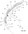
- the ocular implant 100 may further include a coating 129 disposed on the inner surfaces 128 and/or outer surfaces 127 of the implant 100, as shown in Figure 2B . While the coating 129 is illustrated on both the outer and inner surfaces 127, 128, the coating 129 may be on only one of the outer surface 127 or the inner surface 128. Further, while the coating 129 is illustrated as extending over the entirety of the outer surface and the inner surface 127, 128, in some embodiments, the coating 129 may cover only a portion of the outer and/or inner surfaces 127, 128. For example, the coating 129 may cover 10% or more, 25% or more, 50% or more, or 75% or more of the surface area of the ocular implant 100. These are just examples. In some instances, the coating129 may cover less than 10% or more than 75% of the surface area of the implant 100, as desired.
- the coating 129 may be formed of, or otherwise include, a therapeutic agent.
- the coating 129 may release the therapeutic agent.
- the coating 129 may release the therapeutic agent controllably over a period of time.
- the therapeutic agent may be applied directly to the ocular implant 100 while in other embodiments, the ocular implant may be dispersed within a matrix material.
- the therapeutic agent may be dispersed within a biocompatible or biodegradable polymeric material. The concentration of therapeutic agent within the matrix material may vary depending on the desired treatment.
- the biocompatible polymeric material used to form the bioactive agent-polymer composite layer(s) may include any polymeric material capable of forming a solidified composite layer in the presence of the bioactive material.
- the polymeric material of the present invention may be hydrophilic or hydrophobic, and is, for example, polycarboxylic acids, cellulosic polymers, including cellulose acetate and cellulose nitrate, gelatin, polyvinylpyrrolidone, cross-linked polyvinylpyrrolidone, polyanhydrides including maleic anhydride polymers, polyamides, polyvinyl alcohols, polyolefins, copolymers of vinyl monomers such as EVA, polyvinyl ethers, polyvinyl aromatics, polyethylene oxides, glycosaminoglycans, polysaccharides, polyesters including polyethylene terephthalate, polyacrylamides, polyethers, polyether sulfone, polycarbonate, polyalkylenes including polypropylene, polyethylene and
- Coatings from polymer dispersions such as polyurethane dispersions (BAYHDROL ® , etc.) and acrylic latex dispersions are also within the scope of the present invention.
- the polymer may be a protein polymer, fibrin, collagen and derivatives thereof, polysaccharides such as celluloses, starches, dextrans, alginates and derivatives of these polysaccharides, an extracellular matrix component, hyaluronic acid, or another biologic agent or a suitable mixture of any of these, for example.
- the coating 129 can include of a single polymer or copolymer. The coating 129 may also include copolymers or physical blends of any of the materials indicated above.
- the therapeutic agents utilized with the ocular implant may include one or more drugs provided below, either alone or in combination.
- the drugs utilized may also be the equivalent of, derivatives of, or analogs of one or more of the drugs provided below.
- the drugs may include but are not limited to pharmaceutical agents including anti-glaucoma medications, ocular agents, antimicrobial agents (e.g., antibiotic, antiviral, anti parasitic, antifungal agents), anti-inflammatory agents (including steroids or non-steroidal anti-inflammatory), biological agents including hormones, enzymes or enzyme-related components, antibodies or antibody-related components, oligonucleotides (including DNA, RNA, shortinterfering RNA, antisense oligonucleotides, and the like), DNA/RNA vectors, viruses (either wild type or genetically modified) or viral vectors, peptides, proteins, enzymes, extracellular matrix components, and live cells configured to produce one or more biological components.
- antimicrobial agents e.g., antibiotic, antiviral, anti parasitic, antifung
- any particular drug is not limited to its primary effect or regulatory body-approved treatment indication or manner of use.
- Drugs also include compounds or other materials that reduce or treat one or more side effects of another drug or therapeutic agent.
- the listing of any particular drug within any one therapeutic class below is only representative of one possible use of the drug and is not intended to limit the scope of its use with the ophthalmic implant system.
- the therapeutic agents may be combined with any number of excipients as is known in the art.
- excipients including, but not limited to, benzyl alcohol, ethylcellulose, methylcellulose, hydroxymethylcellulose, cetyl alcohol, croscarmellose sodium, dextrans, dextrose, fructose, gelatin, glycerin, mono glycerides, diglycerides, kaolin, calcium chloride, lactose, lactose monohydrate, maltodextrins, polysorbates, pregelatinized starch, calcium stearate, magnesium stearate, silcon dioxide, cornstarch, talc, and the like.
- the one or more excipients may be included in total amounts as low as about 1%, 5%, or 10% and in other embodiments may be included in total amounts as high as 50%, 70% or 90°%.
- drugs may include various anti-secretory agents, antimitotics and other antiproliferative agents, including among others, anti-angiogenesis agents such as angiostatin, anecortave acetate, thrombospondin, VEGF receptor tyrosine kinase inhibitors and anti-vascular endothelial growth factor (anti-VEGF) drugs such as ranibizumab (LUCENTIS ® ) and bevacizumab (AVASTIN ® ), pegaptanib (MACUGEN ® )sunitinib and sorafenib and any of a variety of known small-molecule and transcription inhibitors having anti-angiogenesis effect; classes of known ophthalmic drugs, including: glaucoma agents, such as adrenergic antagonists, including for example, beta-blocker agents such as atenolol propranolol, metipranolol, betaxolol, betaxolol hydrochloride carteolo
- drugs may also include anti-inflammatory agents including for example glucocorticoids and corticosteroids such as betamethasone, cortisone, dexamethasone, dexamethasone 21-phosphate, methylprednisolone, prednisolone 21-phosphate, prednisolone acetate, prednisolone, fluroometholone, loteprednol, medrysone, fluocinolone acetonide, triamcinolone acetonide, triamcinolone, triamcinolone acetonide, beclomethasone, budesonide, flunisolide, fluorometholone, fluticasone, hydrocortisone, hydrocortisone acetate, lotepredtiol, ritnexotone and non-steroidal anti-inflammatory agents including, for example, diclofenac, flurbiprofen, ibuprofen, bromfenac,
- olmesartan such as olmesartan; microtubule inhibitors; molecular motor (dynein and/or kinesin) inhibitors; actin cytoskeleton regulatory agents such as cyctchalasin, latrunculin, swinholide A, ethacrynic acid, H-7, and Rho-kinase (ROCK) inhibitors; remodeling inhibitors; modulators of the extracellular matrix such as tert-butylhydro-quinolone and AL-3037A; adenosine receptor agonists and/or antagonists such as dicyanopyridines, N-6- cylclophexyladenosine and (R)-phenylisopropyladenosine; serotonin agonists; hormonal agents such as estrogens, estradiol, progestational hormones, progesterone, insulin, calcitonin, parathyroid hormone, peptide and vasopressin hypothalamus releasing factor; growth
- Other therapeutic agents may include neuroprotective agents such as lubezole, nimodipine and related compounds, and including blood flow enhancers, sodium channels blockers, glutamate inhibitors such as memantine, neurotrophic factors, nitric oxide synthase inhibitors; free radical scavengers or anti-oxidants; chelating compounds; apoptosis-related protease inhibitors; compounds that reduce new protein synthesis; radiotherapeutic agents; photodynamic therapy agents; gene therapy agents; genetic modulators; and dry eye medications such as cyclosporine A, delmulcents, and sodium hyaluronate.
- neuroprotective agents such as lubezole, nimodipine and related compounds, and including blood flow enhancers, sodium channels blockers, glutamate inhibitors such as memantine, neurotrophic factors, nitric oxide synthase inhibitors; free radical scavengers or anti-oxidants; chelating compounds; apoptosis-related protease inhibitor
- Other therapeutic agents include: other beta-blocker agents such as acebutolol, atenolol, bisoprolol, carvedilol, asmolol, labetalol, nadolol, penbutolol, and pindolol; other corticosteroidal and non-steroidal anti-inflammatory agents such aspirin, betamethasone, cortisone, diflunisal, etodolac, fenoprofen, fludrocortisone, flurbiprofen, hydrocortisone, ibuprofen, indomethacine, ketoprofen, meclofenamate, mefenamic acid, meloxicam, methylprednisolone, nabumetone, naproxen, oxaprozin, prednisolone, prioxicam, salsalate, sulindac and tolmetin; COX-2 inhibitors like celecoxib, rofe
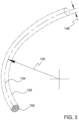
- FIG 3 is an additional perspective view showing volume 152 defined by the body of the ocular implant shown in the previous figure. With reference to Figure 3 , it will be appreciated that volume 152 extends along a generally curved longitudinal axis 134. Volume 152 has a longitudinal radius 150, a lateral radius 148, and a generally circular lateral cross section 153.
- Figure 4 is a perspective view showing a first plane 154 and a second plane 155 that both intersect ocular implant 100.
- first plane 154 is delineated with hatch marks.
- spines 106 of body 102 are generally aligned with one another and that first plane 154 intersects all spines 106 shown in Figure 4 .
- body 102 of ocular implant 100 is generally symmetric about first plane 154.
- the flexibility of body 102 is at a maximum when body 102 is bending along first plane 154, and body 102 has less flexibility when bending along a plane other than first plane 154 (e.g., a plane that intersects first plane 154).
- body 102 has a second flexibility when bending along second plane 155 that is less than the first flexibility that body 102 has when bending along first plane 154.
- the bending modulus of body 102 is at a minimum when body 102 is bent along first plane 154.
- Body 102 has a first bending modulus when bent along first plane 154 and a greater bending modulus when bent along a plane other than first plane 154 (e.g., a plane that intersects first plane 154).
- body 102 has a second bending modulus when bent along second plane 155 that is greater than the first bending modulus that body 102 has when bent along first plane 154.
- Figure 5 is an enlarged perspective view showing a portion of ocular implant 100 shown in the previous figure.
- a bending moment M is being applied to body 102 of ocular implant 100. Bending moment M acts about a first axis 156 that is generally orthogonal to first plane 154.
- a second axis 158 and a third axis 160 are also shown in Figure 5 .
- Second axis 158 is generally perpendicular to first axis 156.
- Third axis 160 is skewed relative to first axis 156.
- Body 102 of ocular implant 100 includes a first edge 120 and a second edge 123 that define a first opening 124.
- Channel 126 of ocular implant 100 fluidly communicates with first opening 124.
- a second opening 138 is defined by a second edge 122A of a first strut 144 and a second edge 122B of a second strut 146.
- First opening 124, second opening 138 and additional openings defined by ocular implant 100 allow aqueous humor to flow laterally across and/or laterally through ocular implant 100.
- ocular implant 100 has a first spine 140 and a second spine 142.
- First strut 144 and a second strut 146 form a first frame 136 of ocular implant 100 that extends between first spine 140 and second spine 142.
- each strut undulates in a circumferential direction as it extends longitudinally between first spine 140 and second spine 142.
- the flexibility of body 102 is at a maximum when body 102 is bent by a moment acting about first axis 156, and body 102 has less flexibility when bent by a moment acting about an axis other than first axis 156 (e.g., second axis 158 and third axis 160).
- the bending modulus of body 102 is at a minimum when body 102 is bent by a moment acting about first axis 156, and body 102 has a greater bending modulus when bent by a moment acting about an axis other than first axis 156 (e.g., second axis 158 and third axis 160).
- FIG 6A is an enlarged perspective view showing a portion of ocular implant 100 shown in the Figures 2 and 4 .
- the ocular implant 100 may further include an intraocular pressure sensor 180 mounted to the inner surface 128 of the ocular implant 100 adjacent to an outlet of the implant 100, as shown in Detail A. While the pressure sensor 180 is illustrated as mounted to an inner surface 1 28 of the ocular implant 100 it is contemplated that the pressure sensor 180 may be mounted within one of the openings 1 24, 138 or on an outer surface of the ocular implant 100, as desired.
- the pressure sensor 180 may continuously measure the intraocular pressure of a patient, once the ocular implant 100 has been implanted.
- the pressure sensor 180 may be a Micro-Electro-Mechanical System (MEMS) pressure sensor. While the pressure sensor 180 has been described as a MEMS pressure sensor, it is contemplated that other pressure sensors may be used in place of, or in addition to, a MEMS pressure sensor. In some instances, the pressure sensor 180 may have a width in the range of approximately 0.02 millimeters (20 micrometers) to approximately 1.0 millimeters. However, it is contemplated that the pressure sensors 180 are smaller than 20 micrometers, or larger than 1.0 millimeter. In some instances, the pressure sensor 180 may have a width dimension in the nanometer range. Further, while only a single pressure sensor 180 has been illustrated, the ocular implant 100 may include more than one pressure sensor 180, as desired.
- MEMS Micro-Electro-Mechanical System
- a first pressure sensor may be placed at a first end of the ocular implant 100 and a second pressure sensor may be placed at a second end of the ocular implant.
- the pressure sensor 180 may be provided in the channel 128 adjacent to the proximal end 101 of the implant 100, as shown in Figure 6C . It is contemplated that the pressure sensor 180 may include a protective cover to prevent the delivery device (not explicitly shown) from damaging the sensor 180 during delivery of the ocular implant 100, although this is not required.
- MEMS pressure sensors are often formed by anisotropically etching a recess into a back side of a silicon substrate die, leaving a thin flexible diaphragm 182.
- an input pressure e.g. the ocular pressure
- the diaphragm 182 deflects according to the magnitude of the input pressure, which may be detected by one or more electrical components or sense elements 186 (e.g. piezoresistors) positioned on or embedded within the diaphragm 182.
- the change in resistance of the piezoresistors 186 is reflected as a change in an output voltage signal from a resistive bridge formed at least in part by the piezoresistors.
- the diaphragm may be made thinner with the addition of support bosses, which may help increase the sensitivity of the diaphragm over a flat plate diaphragm.
- Circuit elements may be connected so that sensor elements 186 to provide some level of signal processing before providing an output signal to bond pads 188 of the pressure sensor 180.
- the signal processing may filter, amplify, linearize, calibrate and/or otherwise process the raw sensor signal produced by the sensor elements (e.g. piezoresistors 186). While the sense elements 186 have been described as piezoresistors, it is contemplated that the sense elements may be selected to provide a capacitive pressure sensor 180.
- the pressure sensor 180 may include a first substrate 185 and a second substrate 183, as shown in Figure 6B , which is a cross-section of the illustrative pressure sensor 180 taken at line B-B in Figure 6A .
- the first substrate 185 may be a layered silicon-insulator-silicon substrate or wafer formed with silicon on insulator (SOI) technology, although this is not required. It is contemplated that other substrates may be used, as desired.
- the first substrate 185 may include a first silicon layer.
- An insulating, or oxide, layer 187 may be disposed on the first silicon layer 185.
- the insulating layer 187 may be formed from silicon dioxide, silicon nitride, sapphire, and/or any other suitable insulating material. While not explicitly shown, the pressure sensor 180 may include a second silicon layer disposed on the insulating layer. In some instances, the second silicon layer may be thinned or removed such that the oxide layer 187 is exposed at the side facing away from the second substrate 183. Alternatively, and in some cases, the second silicon layer and oxide layer 187 are not provided from the start.
- the second substrate 183 may be any semi-conductor wafer (e.g. silicon or germanium) or other substrate as desired. It is contemplated that either or both the first substrate 185 or the second substrate 183 may be doped with an impurity to provide an n-type or p-type extrinsic semiconductor.
- the first substrate 185 may be an n-type substrate while the second substrate 183 may be a p-type substrate.
- the reverse configuration is also contemplated, or both substrates may be doped the same polarity.
- the first substrate 185 and/or the second substrate 183 may include an epitaxial layer.
- piezoresistors 186 may be located in or on the diaphragm 182 to measure deflection/stress of the diaphragm 182 to form a pressure sensor.
- at least one surface of the diaphragm 182 may be exposed to an input pressure.
- the diaphragm 182 may then deflect according to a magnitude of the pressure on the diaphragm 182. A deflection of the diaphragm 182 then creates changes in resistance in the piezoresistors 186.
- a change in resistance of the piezoresistors 186 may be reflected as a change in an output voltage signal of a resistive bridge that is formed at least partially by the piezoresistors 186.
- the output voltage provides a measure of the input pressure exerted on the diaphragm 182.
- the second substrate 183 may be flexible to allow the substrate 183 to be mounted flush against the inner surface 128 of the ocular implant 100.
- the second substrate 183 may have a curved outer surface (facing away from the diaphragm 182) shaped to generally correspond to the curved inner surface 128 of the ocular implant 100.
- the materials forming the pressure sensor 180 may be selected such that the pressure sensor 180 is biocompatible.
- pressure sensor 180 may take other suitable forms.
- the pressure sensor may be formed in such a way that radio waves can be used to detect changes in pressure without sensor elements incorporated into the device.
- a pressure sensor may include a flexible base substrate, a bottom inductive coil positioned on the base substrate, a layer of pressure sensitive rubber pyramids positioned over the bottom inductive coil, a top inductive coil positioned on top of the rubber pyramids, and a top substrate positioned over the top inductive coil.
- Radio waves (from an applied source) reflected by the inductive coils have a lower resonance frequency when the coils are positioned closer together.
- the frequency of the radio waves can indicate the distance between the coils which is then correlated to the pressure exerted on the device.
- the pressure sensor 180 may be further provided with an antenna or inductor 184 to allow the data from the pressure sensor 180 to be wirelessly communicated to a readout device.
- the pressure sensor 180 may use radiofrequency communication protocols, such as, but not limited to cellular communication, ZigBee ® , Bluetooth ® , WiFi ® , IrDA, dedicated short range communication (DSRC), EnOcean ® , Z-Wave, or any other suitable wireless protocols, as desired to transmit the data from the pressure sensor 180 to another device located outside the body.
- radiofrequency communication protocols such as, but not limited to cellular communication, ZigBee ® , Bluetooth ® , WiFi ® , IrDA, dedicated short range communication (DSRC), EnOcean ® , Z-Wave, or any other suitable wireless protocols, as desired to transmit the data from the pressure sensor 180 to another device located outside the body.
- the data may be transmitted to any number so suitably enabled devices, including, but not limited to, cellular phones, tablet or laptop computers, desktop computers, portable handheld devices, such a personal digital assistant (PDA), or a specially designed device, such as, but not limited to a medical device.
- PDA personal digital assistant
- the pressure data may be automatically transmitted to a physician from the remote device.
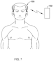
- an enabled remote device 192 may be brought within communication range of the patient's 190 eye. This may allow the enabled device 192 to receive the ocular pressure data recorded at the pressure sensor 180.
- the enabled device 192 may be configured to automatically transmit the data to a physician, for example, to a second remote device.
- an ocular implant may be provided to deliver an intraocular pressure reducing drug (or any other therapeutic agent, including, but not limited to, those described herein with respect to coating 129).
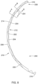
- Figure 8 is a perspective view of an illustrative implant 200 which may be used to deliver a therapeutic agent to the eye over a length of time. It is contemplated that the implant 200 may be configured to deliver the therapeutic agent at a controlled dosage or rate for a period of hours, days, weeks, or even years.
- the therapeutic agent may be delivered for a period of one to twenty years, five to fifteen years, or about 10 years.
- the implant 200 may be configured to deliver a therapeutic agent for less than a year, or more than twenty years, as desired. It is contemplated that the length of time the implant 200 is capable of delivering a therapeutic agent may depend on the size of the implant, the quantity of the therapeutic agent loaded into the stent, the delivery rate of the therapeutic agent, other biological factors dependent on the patient, and/or combinations thereof.
- the implant 200 may include a body portion 202 similar in form and function to the body 102 and frame 104 described above with respect to ocular implant 100.
- the body portion 202 may include a frame 206 having a plurality of splines 204 and a plurality of struts 208 extending between the splines 204.
- the frame 206 may include a first opening 210 (or plurality of openings) configured to be positioned in a radially outward positioned (similar to opening 124 described above).
- the frame 206 may include a second opening 212 (or plurality of openings) configured to be poisoned in a radially inward position (e.g., facing the anterior chamber 30).
- a longitudinally extending channel 220 extends from a proximal end 216 of the implant 200 to a distal end 218 of the implant 200.
- a polymer rod 214 loaded with a therapeutic agent 218 is positioned within the longitudinally extending channel 220.
- the polymer rod 214 may be formed from a biocompatible polymer such as, but not limited to polysiloxanes (e.g., silicone), polyurethane, polylactic acid (PLA), polyvinyl alcohol, poly(lactic-co-glycolic) acid (PLGA), polyethylene, polyethylene oxide, polyethylene terephthalate, or polyester, or mixtures, combinations, blends or co-polymers thereof, or the like.
- polysiloxanes e.g., silicone
- PLA polylactic acid
- PLGA poly(lactic-co-glycolic) acid
- polyethylene polyethylene oxide
- polyethylene terephthalate polyethylene terephthalate
- polyester or mixtures, combinations, blends or co-polymers thereof, or the like.
- all or a portion of the polymer rod 214 may be porous thereby allowing certain substances to permeate or diffuse through a side wall of the polymer rod 214 and into pores or interstitial spaces within the rod 214.
- the porosity (e.g., the percentage of interstitial volume to total volume) of the polymer rod 214 may be about 10% or more, about 20% or more, about 30% or more, about 40% or more, about 50% or more, about 60% or more, about 70% or more, or about 80% or more, for example.
- the polymer rod 214 may be loaded with a therapeutic agent 218 (see, for example, Figures 9A and 9B ).
- a therapeutic agent 218 see, for example, Figures 9A and 9B .
- the interstitial spaces of the polymer rod 214 may be filled with one or more therapeutic agent 218.
- the polymer rod 214 may be filled with a therapeutic agent 218 such that the rod 214 has a precise quantity of the therapeutic agent.
- the therapeutic agent 218 may diffuse through the porous sidewall of the polymer rod 214 over a predetermined period of time dictated, at least in part, by the average pore size of the porous sidewall of the rod 214.
- the rate of release of the therapeutic agent 218 may be known and dictated, at least in part, by the porosity of the rod 214.
- the porosity of the rod 214 may be chosen to controllably release the therapeutic agent 218 over a period of minutes, hours, days, weeks, months, years, etc.
- the duration of release of the therapeutic agent 218 from the rod 214 may be about 1 hour, about 2 hours, about 3 hours, about 4 hours, about 5 hours, about 6 hours, about 12 hours, about 1 day, about 2 days, about 3 days, about 4 days, about 5 days, about 6 days, about 1 week, about 2 weeks, about 3 weeks, about 1 month, about 2 months, about 3 months, about 4 months, about 5 months, about 6 months, about 7 year, about 2 years, about 5 years, about 10 years, or longer.
- the polymer rod 214 may be chosen for its porosity such that a desired rate of therapeutic agent release is provided.
- the therapeutic agent 218 and the monomer or polymer for forming the polymer rod 214 may be injected into the channel 220 as a liquid or slurry and solidified within the channel 220. It is contemplated that solidification of the polymer may include exposing the device 200 to a cross-link initiator, such as a UV light source, heat, reagents, etc. In other cases, the polymer rod 214 and therapeutic agent 218 may be formed outside of the channel 220 and is subsequently loaded into the channel 220.
- a cross-link initiator such as a UV light source, heat, reagents, etc.
- Figure 9A is a lateral cross-sectional view of ocular implant 200 taken along section line A-A shown in Figure 8 .
- Section line A-A intersects a pair of struts 208 of the frame 206 at the point where the circumferential undulation of these struts is at its maximum.
- the polymer rod 214 is positioned within the channel 220.
- a first opening 212 fluidly communicates with channel 126.
- Figure 9B is a lateral cross-sectional view of ocular implant 200 taken along section line B-B shown in the Figure 8 .
- Section line B-B intersects a spine 204 of ocular implant 200.
- the frame 206 and/or polymer rod 214 may be wrapped with a sleeve 216 to hold the rod 214 in place.
- the sleeve 216 may be a silicone sleeve, or other porous material, configured to control elution, although this is not required. It is contemplated that the sleeve 216 may have a pore size selected to control the release of the therapeutic agent 218.
- the sleeve 216 and/or frame 206 may be provided with additional openings or windows on the radially inwards surface to direct the therapeutic agent 218 towards the anterior chamber of the eye.
- the sleeve 216 if so provided, or the outer surface of the frame 206 and rod 214 may be coated with heparin or a heparin related coating to prevent the adhesion of tissue or other debris on the surface of the device 200 which may inhibit drug elution.
- the ocular implant 200 may be inserted into Schlemm's canal such that it is fixed and not free floating (as it may if placed in the anterior chamber). This may reduce the likelihood of the implant 200 damaging the cornea or other structures through movement Further, the placement of the implant 200 in Schlemm's canal may place the therapeutic agent 218 in continuous contact with the aqueous humor that reaches the implant 200 by the trabecular meshwork.
- FIG 10 is a perspective view of another illustrative implant 300 which may be used to deliver a therapeutic agent to the eye over a length of time either in addition to or in place of an ocular implant, such as implant 100, configured and positioned to facilitate the flow of aqueous humor out of the anterior chamber.
- the implant 300 may be configured to deliver the therapeutic agent at a controlled dosage or rate for a period of hours, days, weeks, or even years.
- the therapeutic agent may be delivered for a period of one to twenty years, five to fifteen years, or about 10 years.
- the implant 300 may be configured to deliver a therapeutic agent for less than a year, or more than twenty years, as desired.
- the length of time the implant 300 is capable of delivering a therapeutic agent may depend on the size of the implant, the quantity of the therapeutic agent loaded into the stent, the delivery rate of the therapeutic agent, other biological factors dependent on the patient, and/or combinations thereof.
- the implant 300 may include an elongated tubular body 302 extending from a proximal end 306 to a distal end 304.
- a lumen 308 extends from the proximal end 306 to the distal end 304.
- the distal end 304 may be tapered or pointed to facilitate advancement through the eye, although this is not required.
- the proximal end 306 may include interlocking features 314 configured to engage mating features on a delivery device, similar to that described with respect to Figures 19A and 19B .
- the elongated tubular body 302 may be curved along its longitudinal axis in a similar manner to the implant 100 described above.
- the elongated tubular body 302 may a nitinol, stainless steel, or other material, as desired.
- the elongated tubular body 302 may include a plurality of micro pores extending from an inner surface to an outer surface of the tubular body 302 (e.g., from the lumen 308 top a point exterior to the tubular body 302) to allow a therapeutic agent to pass from the lumen 308 to a point exterior to the elongated tubular body 302.
- the micro pores may be present on the radially inwards portions of the tubular member 302 to direct a therapeutic agent towards the anterior chamber of the eye. However, this is not required.
- the micro pores may be on a radially outward portion of the tubular body 302, the entire tubular body 302, a portion of a length of the tubular body 302, and/or a portion of the circumference the tubular body 302, as desired.
- a polymer rod 310 loaded with a therapeutic agent 312 is positioned within the lumen 308, as shown in Figure 11 which illustrates a lateral cross-sectional view of ocular implant 300 taken along section line A-A shown in Figure 10 .
- the polymer rod 310 may be formed from a biocompatible polymer such as, but not limited to polysiloxanes (e.g., silicone), polyurethane, polylactic acid (PLA), polyvinyl alcohol, poly(lactic-co-glycolic) acid (PLGA), polyethylene, polyethylene oxide, polyethylene terephthalate, or polyester, or mixtures, combinations, blends or co-polymers thereof, or the like.
- the polymer rod 310 may be porous thereby allowing certain substances to permeate or diffuse through a side wall of the polymer rod 310 and into pores or interstitial spaces within the rod 310.
- the porosity (e.g., the percentage of interstitial volume to total volume) of the polymer rod 310 may be about 10% or more, about 20% or more, about 30% or more, about 40% or more, about 50% or more, about 60% or more, about 70% or more, or about 80% or more, for example.
- the polymer rod 310 may be loaded with a therapeutic agent 312.
- the therapeutic agent may be an intraocular pressure reducing drug (or any other therapeutic agent, including, but not limited to, those described herein with respect to coating 129).
- the interstitial spaces of the polymer rod 310 may be filled with one or more therapeutic agent 312. It is contemplated that the polymer rod 310 may be filled with a therapeutic agent 312 such that the rod 310 has a precise quantity of the therapeutic agent.
- the therapeutic agent 312 may diffuse through the porous sidewall of the polymer rod 310 and the porous wall of the tubular body 302 over a predetermined period of time dictated, at least in part, by the average pore size of the porous sidewall of the rod 310 and/or the tubular body 302.
- the rate of release of the therapeutic agent 312 may be known and dictated, at least in part, by the porosity of the rod 310.
- the porosity of the rod 310 and/or tubular body 302 may be chosen to controllably release the therapeutic agent 312 over a period of minutes, hours, days, weeks, months, years, etc.
- the duration of release of the therapeutic agent 312 from the rod 310 may be about 1 hour, about 2 hours, about 3 hours, about 4 hours, about 5 hours, about 6 hours, about 12 hours, about 1 day, about 2 days, about 3 days, about 4 days, about 5 days, about 6 days, about 1 week, about 2 weeks, about 3 weeks, about 1 month, about 2 months, about 3 months, about 4 months, about 5 months, about 6 months, about 1 year, about 2 years, about 5 years, about 10 years, or longer.
- the polymer rod 310 and/or tubular body 302 may be chosen for its porosity such that a desired rate of therapeutic agent release is provided.
- the therapeutic agent 312 and the monomer or polymer for forming the polymer rod 310 may be injected into the lumen 308 as a liquid or slurry and solidified within the lumen 308. It is contemplated that solidification of the polymer may include exposing the device 300 to a cross-link initiator, such as a UV light source, heat, reagents, etc. In other cases, the polymer rod 310 and therapeutic agent 312 may be formed outside of the lumen 308 and is subsequently loaded into the lumen 308.
- the elongated tubular body 302 may be coated with heparin or a heparin related coating to prevent the adhesion of tissue or other debris on the surface of the implant 300 which may inhibit drug elution.
- the ocular implant 300 may be inserted into Schlemm's canal such that it is fixed and not free floating (as it may if placed in the anterior chamber). This may reduce the likelihood of the implant 300 damaging the cornea or other structures through movement. Further, the placement of the implant 300 in Schlemm's canal may place the therapeutic agent 312 in continuous contact with the aqueous humor that reaches the implant 300 by the trabecular meshwork.
- Figure 12 is a perspective view of another illustrative implant 330 which may be used to deliver a therapeutic agent to the eye over a length of time either in addition to or in place of an ocular implant, such as implant 100, configured and positioned to facilitate the flow of aqueous humor out of the anterior chamber.
- the implant 330 may be configured to deliver the therapeutic agent at a controlled dosage or rate for a period of hours, days, weeks, or even years.
- the therapeutic agent may be delivered for a period of one to twenty years, five to fifteen years, or about 10 years.
- the implant 330 may be configured to deliver a therapeutic agent for less than a year, or more than twenty years, as desired.
- the length of time the implant 330 is capable of delivering a therapeutic agent may depend on the size of the implant, the quantity of the therapeutic agent loaded into the stent, the delivery rate of the therapeutic agent, other biological factors dependent on the patient, and/or combinations thereof.
- the implant 330 may include an elongated body 332 extending from a proximal end 336 to a distal end 334.
- the proximal end 336 may include interlocking features 338 configured to engage mating features on a delivery device, similar to that described with respect to Figures 19A and 19B .
- the elongated body 332 may have a generally porous but otherwise substantially solid cross-section (see, for example, Figure 13 , which illustrates a lateral cross-sectional view of ocular implant 300 taken along section line A-A shown in Figure 12 ). In other words, the elongated body 332 may lack the elongated lumen and/or channels of other implants described herein.
- the elongated body 332 may be curved along its longitudinal axis in a similar manner to the implant 100 described above.
- the elongated body 332 may be formed from a biocompatible polymer such as, but not limited to polysiloxanes (e.g., silicone), polyurethane, polylactic acid (PLA), polyvinyl alcohol, poly(lactic-co-glycolic) acid (PLGA), polyethylene, polyethylene oxide, polyethylene terephthalate, or polyester, or mixtures, combinations, blends or co-polymers thereof, or the like.
- the polymer may be biodegradable.
- all or a portion of the elongated body 332 may be porous thereby allowing certain substances to permeate or diffuse through a side wall of the elongated body 332 and into pores or interstitial spaces within the elongated body 332.
- the porosity e.g., the percentage of interstitial volume to total volume
- the porosity of the elongated body 332 may be about 10% or more, about 20% or more, about 30% or more, about 40% or more, about 50% or more, about 60% or more, about 70% or more, or about 80% or more, for example.
- the elongated body 332 may be loaded with a therapeutic agent 340.
- the therapeutic agent may be an intraocular pressure reducing drug (or any other therapeutic agent, including, but not limited to, those described herein with respect to coating 129).
- the interstitial spaces of the elongated body 332 may be filled with one or more therapeutic agent 340. It is contemplated that the elongated body 332 may be filled with a therapeutic agent 340 such that the elongated body 332 has a precise quantity of the therapeutic agent.
- the therapeutic agent 340 may diffuse through the porous sidewall of the elongated body 332 and the porous wall of the tubular body 332 over a predetermined period of time dictated, at least in part, by the average pore size of the porous sidewall of the elongated body 332 and/or the tubular body 332.
- the rate of release of the therapeutic agent 340 may be known and dictated, at least in part, by the porosity of the elongated body 332.
- the porosity of the elongated body 332 and/or tubular body 332 may be chosen to controllably release the therapeutic agent 340 over a period of minutes, hours, days, weeks, months, years, etc.
- the duration of release of the therapeutic agent 340 from the elongated body 332 may be about 1 hour, about 2 hours, about 3 hours, about 4 hours, about 5 hours, about 6 hours, about 12 hours, about 1 day, about 2 days, about 3 days, about 4 days, about 5 days, about 6 days, about 1 week, about 2 weeks, about 3 weeks, about 1 month, about 2 months, about 3 months, about 4 months, about 5 months, about 6 months, about 1 year, about 2 years, about 5 years, about 10 years, or longer.
- the elongated body 332 and/or tubular body 332 may be chosen for its porosity such that a desired rate of therapeutic agent release is provided.
- the elongated tubular body 332 may be coated with heparin or a heparin related coating to prevent the adhesion of tissue or other debris on the surface of the implant 330 which may inhibit drug elution.
- the ocular implant 330 may be inserted into Schlemm's canal such that it is fixed and not free floating (as it may if placed in the anterior chamber). This may reduce the likelihood of the implant 330 damaging the cornea or other structures through movement. Further, the placement of the implant 400 in Schlemm's canal may place the therapeutic agent 340 in continuous contact with the aqueous humor that reaches the implant 330 by the trabecular mesh work.
- Figure 14 is a perspective view of another illustrative implant 350, which may be used to deliver a therapeutic agent to the eye over a length of time either in addition to or in place of an ocular implant, such as implant 100, configured and positioned to facilitate the flow of aqueous humor out of the anterior chamber.
- the implant 350 may be configured to deliver the therapeutic agent at a controlled dosage or rate for a period of hours, days, weeks, or even years.
- the therapeutic agent may be delivered for a period of one to twenty years, five to fifteen years, or about 10 years.
- the implant 350 may be configured to deliver a therapeutic agent for less than a year, or more than twenty years, as desired.
- the length of time the implant 350 is capable of delivering a therapeutic agent may depend on the size of the implant, the quantity of the therapeutic agent loaded into the stent, the delivery rate of the therapeutic agent, other biological factors dependent on the patient, and/or combinations thereof.
- the implant 300 may include an elongated tubular body 352 extending from a proximal end 356 to a distal end 354.
- a lumen 358 extends from the proximal end 356 to the distal end 354.
- the distal end 354 may be tapered or pointed to facilitate advancement through the eye, although this is not required.
- the proximal end 356 may include interlocking features 360 configured to engage mating features on a delivery device, similar to that described with respect to Figures 19A and 19B .
- the elongated tubular body 352 may be curved along its longitudinal axis in a similar manner to the implant 1 00 described above.
- the elongated tubular body 352 may a nitinol, stainless steel, or other material, as desired.
- a therapeutic agent 362 may be loaded within the lumen 358, as shown in Figure 15 which illustrates a lateral cross-sectional view of ocular implant 300 taken along section line A-A shown in Figure 14 .
- the therapeutic agent 362 may be an intraocular pressure reducing drug (or any other therapeutic agent, including, but not limited to, those described herein with respect to coating 129).
- the lumen 358 of the implant 350 may be filled with one or more therapeutic agents 362. It is contemplated that the lumen 358 may be filled with a therapeutic agent 362 such that the implant 350 has a precise quantity of the therapeutic agent 362.
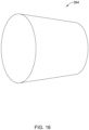
- the lumen 358 may be blocked or plugged adjacent the distal and/or proximal ends 354, 356 using a removable plug, cap, or stopper such as the plug 364 illustrated in Figure 16 .
- the plug 364 may have a tapered configuration.
- the plug 364 may have a uniform diameter from a first end to a second end thereof. It is contemplated that the plug 364 may form a friction fit within the lumen 358 to substantially block the flow of therapeutic agent from the lumen 358 of the implant 350.
- the plug 364 may formed, at least in part, from a polymer configured to limit or control diffusion of the therapeutic agent 362.
- the plug 364 may be formed from a biocompatible polymer such as, but not limited to polysiloxanes (e.g., silicone), polyurethane, polylactic acid (PLA), polyvinyl alcohol, poly(lactic-co-glycolic) acid (PLGA), polyethylene, polyethylene oxide, polyethylene terephthalate, or polyester, or mixtures, combinations, blends or co-polymers thereof, or the like.
- the polymer may be biodegradable.
- all or a portion of the plug 364 may be porous thereby allowing certain substances to permeate or diffuse through the plug 364.
- the porosity (e.g., the percentage of interstitial volume to total volume) of the plug 364 may be about 10% or more, about 20% or more, about 30% or more, about 40% or more, about 50% or more, about 60% or more, about 70% or more, or about 80% or more, for example.
- the polymer may be injected into a metal cap or frame.
- the plug 356 may be formed entirely from the polymeric material. It is contemplated that in some cases, the body 352 of the implant 302 may also be porous, as described herein, to further control diffusion of the therapeutic agent 362.
- the therapeutic agent 362 may diffuse through the porous plug 364 over a predetermined period of time dictated, at least in part, by the average pore size of the plug 364.
- the rate of release of the therapeutic agent 362 may be known and dictated, at least in part, by the porosity of the plug 364.
- the porosity of the plug 364 may be chosen to controllably release the therapeutic agent 362 over a period of minutes, hours, days, weeks, months, years, etc.
- the duration of release of the therapeutic agent 362 from the implant 350 may be about 1 hour, about 2 hours, about 3 hours, about 4 hours, about 5 hours, about 6 hours, about 12 hours, about 1 day, about 2 days, about 3 days, about 4 days, about 5 days, about 6 days, about 1 week, about 2 weeks, about 3 weeks, about 1 month, about 2 months, about 3 months, about 4 months, about 5 months, about 6 months, about 1 year, about 2 years, about 5 years, about 10 years, or longer.
- the polymer rod 310 and/or tubular body 352 may be chosen for its porosity such that a desired rate of therapeutic agent release is provided.
- the elongated tubular body 352 may be coated with heparin or a heparin related coating to prevent the adhesion of tissue or other debris on the surface of the implant 300 which may inhibit drug elution.
- the ocular implant 350 may be inserted into Schlemm's canal such that it is fixed and not free floating (as it may if placed in the anterior chamber). This may reduce the likelihood of the implant 350 damaging the cornea or other structures through movement. Further, the placement of the implant 350 in Schlemin's canal may place the therapeutic agent 362 in continuous contact with the aqueous humor that reaches the implant 350 by the trabecular meshwork.
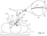
- Figure 17 is a stylized representation of a medical procedure in accordance with this detailed description.
- a physician is treating an eye 400 of a patient P.
- the physician is holding a hand piece of a delivery system 450 in his or her right hand RH.
- the physician's left hand (not shown) may be used to hold the handle H of a gonio lens 402.
- some physicians may prefer holding the delivery system hand piece in the left hand and the gonio lens handle H in the right hand RH.
- Further details of ocular implant delivery systems may be found in U.S. Application No. 11/943,289, filed November 20, 2007 , now U.S. Patent No. 8,512,404 , the disclosure of which is incorporated herein by reference.
- the physician may view the interior of the anterior chamber using gonio lens 402 and a microscope 404.
- Detail A of Figure 17 is a stylized simulation of the image viewed by the physician.
- a distal portion of a cannula 452 is visible in Detail A.
- a shadow-like line indicates the location of Schlemm's canal SC which is lying under various tissues (e.g., the trabecular meshwork) that surround the anterior chamber.
- a distal opening 454 of cannula 452 is positioned near Schlemm's canal SC of eye 400.
- Methods in accordance with this detailed description may include the step of advancing the distal end of cannula 452 through the cornea of eye 400 so that a distal portion of cannula 452 is disposed in the anterior chamber of the eye.
- Cannula 452 may then be used to access Schlemm's canal of the eye, for example, by piercing the wall of Schlemm's canal with the distal end of cannula 452.
- Distal opening 454 of cannula 452 may be placed in fluid communication with a lumen defined by Schlemm's canal.
- the ocular implant may be advanced out of distal opening 454 and into Schlemm's canal. Insertion of the ocular implant into Schlemm's canal may facilitate the flow of aqueous humor out of the anterior chamber of the eye.
- Figure 18 is an enlarged perspective view further illustrating delivery system 450 and eye 400 shown in the previous figure.
- cannula 452 of delivery system 450 is shown extending through a cornea 426 of eye 400.
- a distal portion of cannula 452 is disposed inside the anterior chamber defined by cornea 426 of eye 400.
- cannula 452 is configured so that a distal opening 454 of cannula 452 can be placed in fluid communication with Schlemm's canal.
- an ocular implant is disposed in a passageway defined by cannula 452.
- Delivery system 450 includes a mechanism that is capable of advancing and retracting the ocular implant along the length of cannula 452.
- the ocular implant may be placed in Schlemm's canal of eye 400 by advancing the ocular implant through the distal opening of cannula 452 while the distal opening is in fluid communication with Schlemm's canal.
- FIG 19A is a perspective view showing a delivery system 500 including an ocular implant 550 and a cannula 508 defining a passageway that is dimensioned to slidingly receive ocular implant 550.
- Delivery system 500 may be used to advance ocular implant 550 into a target location in the eye of a patient. Examples of target locations that may be suitable in some applications include areas in and around Schlemm's canal, the trabecular meshwork, the suprachoroidal space, and the anterior chamber of the eye.
- Figure 19B is an enlarged detail view further illustrating ocular implant 550 and cannula 508 of delivery system 500.
- Delivery system 500 of Figure 19A is capable of controlling the advancement and retraction of ocular implant 550 within cannula 508.
- Ocular implant 550 may be placed in a target location (e.g., Schlemm's canal) by advancing the ocular implant through a distal opening 532 of cannula 508 while the distal opening is in fluid communication with Schlemm's canal.
- a target location e.g., Schlemm's canal
- ocular implant 550 has been advanced through distal opening 532 of cannula 508 for purposes of illustration.
- Delivery system 500 of Figure 19A includes a housing 502, a sleeve 504, and an end cap 510.
- a tracking wheel 506 extends through a wall of housing 502 in Figure 19A .
- Tracking wheel 506 is part of a mechanism that is capable of advancing and retracting a delivery tool 552 of delivery system 500.
- the delivery tool 552 extends through a distal opening of cannula 508 of Figure 19B .
- Rotating the tracking wheel will cause delivery tool 552 to move in an axial direction along a passageway defined by cannula 508.
- the axial direction may be in a distal direction D or a proximal direction P.
- the delivery tool 552 and the mechanism for moving the delivery tool 552 are described in commonly assigned application serial number 62/024,295, which is herein incorporated by reference.
- housing 502 is configured to be gripped with one hand while providing control over the axial advancement and retraction of ocular implant via tracking wheel 506.
- the housing of delivery system 500 results in an advantageous ergonomic relationship of the fingers relative to the hand. This design provides a configuration that will allow a user, such as a physician, to stabilize the device using part of the hand, while leaving the middle or index finger free move independently from the remainder of the hand. The middle or index finger is free to move independently to rotate the wheel for advancing and/or retract the ocular implant.
- Figure 19B is an enlarged detail view further illustrating ocular implant 550 and a cannula 508 of delivery system 500.
- Cannula 508 comprises a generally tubular member 598 having proximal portion 540, a distal end 534, and a distal portion 544 extending between distal end 534 and proximal portion 540.
- distal portion 544 is curved.
- distal portion 544 is dimensioned and configured to be received in the anterior chamber of the eye.
- Figure 19B shows delivery tool 552 of delivery system 500 extending through distal opening 532 of cannula 508.
- Delivery tool 552 includes an interlocking portion 560 that is configured to form a connection with a complementary interlocking portion 562 of ocular implant 550, as explained in more detail below.
- rotating the tracking wheel will cause delivery tool 552 and ocular implant 550 to move along a path defined by cannula 508.
- Cannula 508 is sized and configured so that the distal end of cannula 508 can be advanced through the trabecular meshwork of the eye and into Schlemm's canal. Positioning cannula 508 in this way places distal opening 532 in fluid communication with Schlemm's canal.
- Ocular implant 550 may be placed in Schlemm's canal by advancing the ocular implant through distal opening 532 of cannula 508 while the distal opening is in fluid communication with Schlemm's canal.
- the distal portion of the cannula may include a cutting portion configured to cut through the trabecular meshwork and the wall of Schlemm's canal, such as by providing distal end 534 with a sharp edge adapted to cut through such tissue.
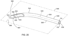
- FIG 20 is a perspective view of a cannula 508 in accordance with the present detailed description.
- Cannula 508 of Figure 20 comprises a generally tubular member 598 having a central axis 596.
- Generally tubular member 598 of Figure 20 comprises a proximal portion 540, a distal end 534, and a distal portion 544 extending between distal end 534 and proximal portion 540.
- a distal opening surface 542 surrounds a distal opening 532 extending through the distal end 534 and through a side wall of cannula 508.
- a beveled edge 565 is disposed at the distal end of distal opening surface 542, extending from the distal end 534 to a proximal extent 567 of beveled edge 565.
- Tubular member 598 defines distal opening 532, a proximal opening 536, and a passageway 538 extending between proximal opening 536 and distal opening 532.
- proximal portion 540 of cannula 508 is substantially straight, distal portion 544 of cannula 508 is curved, and central axis 596 defines a curvature plane 548.
- Curvature plane 548 may be referred to as a plane of curvature.
- Curvature plane 548 divides cannula 508 into a first portion PA and a second portion PB.
- second portion PB is substantially a mirror image of first portion PA.
- distal portion 544 is shown extending between distal end 534 and proximal portion 540 with no intervening elements.
- distal portion 544 is curved along its entire length.
- a method in accordance with this detailed description may include the step of advancing the distal end 534 of cannula 508 through the cornea of a human eye so that distal end 534 is disposed in the anterior chamber of the eye.
- Cannula 508 may then be used to access Schlemm's canal of the eye, for example, by piercing the wall of Schlemm's canal with the distal end 534 of cannula 508.
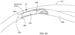
- the beveled edge 565 may be inserted into Schlemm's canal to place at least part of distal opening 532 of cannula 508 in communication with Schlemm's canal, as discussed in more detail below.
- the ocular implant may be advanced out of a distal port of the cannula and into Schlemm's canal.
- distal portion 544 of cannula 508 defines a trough 554.
- trough 554 is configured to receive the entire external cross section of an ocular implant as the ocular implant is being advanced into Schlemm's canal.
- trough 554 may have a depth dimension that is deeper than a width of the ocular implant. This cannula configuration advantageously prevents the ocular implant from intersecting the layers of the trabecular meshwork as the ocular implant is advanced into Schlemm's canal.
- Trough 554 may also be configured to allow the proximal portion of the ocular implant to be released from the delivery tool, as discussed below.
- the cannula 508 may further include a pressure sensor 580 disposed within the trough 554.
- the pressure sensor 580 may be similar in form and function to pressure sensor 180 described above. While the pressure sensor 580 is illustrated as mounted within the trough 554 of the cannula, it is contemplated that the pressure sensor 580 may be mounted at other locations within or on the cannula 508.
- the pressure sensor 580 may provide an instantaneous pressure reading during implantation of the ocular implant 550 or shortly thereafter. In some instances, the pressure reading obtained from the pressure sensor 580 on the cannula 508 can be compared to a pressure reading obtained from a pressure sensor mounted on the ocular implant 550, if so provided.
- the pressure sensor 580 may be a Micro-Electro-Mechanical System (MEMS) pressure sensor. While the pressure sensor 580 has been described as a MEMS pressure sensor, it is contemplated that other pressure sensors may be used in place of, or in addition to, a MEMS pressure sensor. Further, while only a single pressure sensor 580 has been illustrated, the cannula 508 may include more than one pressure sensor 580, as desired. MEMS pressure sensors are often formed by anisotropically etching a recess into a back side of a silicon substrate die, leaving a thin flexible diaphragm. In operation, at least one surface of the diaphragm is exposed to an input pressure (e.g. the ocular pressure).
- MEMS pressure sensors are often formed by anisotropically etching a recess into a back side of a silicon substrate die, leaving a thin flexible diaphragm. In operation, at least one surface of the diaphragm is exposed to an input pressure (e.g. the
- the diaphragm deflects according to the magnitude of the input pressure, which may be detected by one or more electrical components or sense elements (e.g. piezoresistors) positioned on or embedded within the diaphragm.
- the change in resistance of the piezoresistors is reflected as a change in an output voltage signal from a resistive bridge formed at least in part by the piezoresistors.
- the diaphragm may be made thinner with the addition of support bosses, which may help increase the sensitivity of the diaphragm over a flat plate diaphragm.
- Circuit elements may be connected so that sensor elements to provide some level of signal processing before providing an output signal to bond pads of the pressure sensor.
- the signal processing may filter, amplify, linearize, calibrate and/or otherwise process the raw sensor signal produced by the sensor elements (e.g. piezoresistors). While the sense elements have been described as piezoresistors, it is contemplated that the sense elements may be selected to provide a capacitive pressure sensor 580.
- the sensor elements e.g. piezoresistors
- the pressure sensor 580 may be further provided with an antenna or inductor to allow the data from the pressure sensor 580 to be wirelessly communicated to a readout device.
- the pressure sensor 580 may use radiofrequency communication protocols, such as, but not limited to cellular communication, ZigBee ® , Bluetooth ® , WiFi ® , IrDA, dedicated short range communication (DSRC), EnOcean ® , or any other suitable wireless protocols, as desired to transmit the data from the pressure sensor 580 to another device located outside the body.
- the data may be transmitted to any number so suitably enabled devices, including, but not limited to, cellular phones, tablet computers, computers, portable handheld devices, such a personal digital assistant (PDA), or a specially designed device. This may allow a physician, patient, or other interested party to monitor the ocular pressure without the use of a tonometer.
- PDA personal digital assistant
- Figure 21 is a perspective view of an assembly including cannula 508 shown in the previous figure.
- cannula 508 is cross-sectionally illustrated in Figure 26 .
- an ocular implant 550 can be seen resting in a passageway 538 defined by cannula 508.
- distal portion 544 of cannula 508 is curved so that central axis 596 of cannula 508 defines a curvature plane 548.
- curvature plane 548 divides cannula 508 into a first portion and a second portion PB. Only second portion PB of cannula 508 is shown in the illustrative embodiment of Figure 21 .
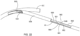
- Figure 22 is a stylized perspective view including the assembly shown in the previous figure.
- a distal portion of cannula 508 is shown extending through the wall of Schlemm's canal SC.
- the distal tip of cannula 508 may include a sharp portion configured for cutting and/or piercing the trabecular meshwork and the wall of Schlemm's canal so that the passageway defined by the cannula can be placed in fluid communication with the lumen defined by Schlemm's canal.
- ocular implant 550 With the passageway of the cannula placed in fluid communication with the lumen of Schlemm's canal, ocular implant 550 can be advanced out of the distal opening of the cannula and into Schlemm's canal.
- a distal portion of ocular implant 550 can be seen through distal opening 532 of cannula 508.
- a hypothetical witidow W is cut through the wall of cannula 508 in Figure 22 .
- An interlocking portion 560 of a delivery tool 552 and a complementary interlocking portion 562 of ocular implant 550 are visible through window W.
- interlocking portion 560 of delivery tool 552 and complementary interlocking portion 562 of ocular implant 550 are engaging each other so that a proximal end 549 of ocular implant 550 is proximal to the distal end 551 of delivery tool 552.
- Delivery tool 552 rests against the wall of cannula 508 to prevent interlocking portion 560 of delivery tool 552 and complementary interlocking portion 562 of ocular implant 550 from disengaging one another.
- delivery tool 552 and ocular implant 550 move together as the delivery tool is advanced and retracted relative to cannula 508 by the delivery system mechanism.
- Figure 23 is an enlarged perspective view showing a portion of cannula 508 shown in the previous figure.
- cannula 508 is curved to achieve substantially tangential entry into Schlemm's canal SC.
- cannula 508 is contacting an outer major wall of Schlemm's canal SC at a point of tangency PT.
- a curved distal portion of cannula 508 is dimensioned to be disposed within the anterior chamber of the eye.
- the distal tip 534 and beveled edge of the cannula 508 have been inserted into Schlemm's canal up to the proximal extent 567 of beveled edge 565.
- ocular implant 550 can be seen extending into trough 554.
- the ocular implant has a radius of curvature that is larger than the radius of curvature of the cannula. This arrangement ensures that the ocular implant will track along trough 554 as the ocular implant is urged in a distal direction by delivery system 500.
- Figure 24 is an additional perspective view showing ocular implant 550 and cannula 508 shown in the previous figure.
- ocular implant 550 has been advanced in a distal direction D while cannula 508 has remained stationary so that a distal portion of ocular implant 550 is disposed inside Schlemm's canal SC.
- Trough 554 opens into an elongate opening 532 defined by edge 542 at the distal portion of cannula 508.
- the elongate opening defined by the cannula provides direct visualization of the ocular implant as it is advanced into Schlemm's canal.
- a configuration allowing direct visualization of the ocular implant has a number of clinical advantages.
- ocular implant 550 tracks along trough 554 as it is advanced distally along cannula 508.
- the trough opening allows the physician to monitor the progress of the implant by viewing the implant structures as they advance through the trough prior to entering Schlemm's canal.
- the trough opening also allows the physician to identify the position of the proximal end of the ocular implant with respect to the incision made by the cannula to access Schlemm's canal.
- Figure 25 is an additional stylized perspective view showing ocular implant 550 and cannula 508.
- the interlocking portions 560 and 562 of the delivery tool 552 and ocular implant 550, respectively, can be seen entering the distal opening 532 defined by cannula 508.
- ocular implant 550 has been advanced in a distal direction D (relative to the embodiment shown in the previous figure) so that more of ocular implant 550 is disposed inside Schlemm's canal SC.
- Surface 561 opposite interlocking portion 560 of delivery tool 552 still rests against the inner wall of cannula 508 to keep the delivery tool interlocked with ocular implant 550.
- Figure 26 is an additional stylized perspective view showing ocular implant 550 and cannula 508.
- the ocular implant 550 and delivery tool 552 have advanced further distally so that delivery tool surface 561 and part of the reduced diameter portion 563 have now passed into opening 532, thereby permitting the delivery tool curved portion 553 to move toward its curved at-rest shape so that the delivery tool engagement surface 560 disengages and moves away from its complementary engagement surface 562 on the ocular implant 550.
- the delivery tool may be colored to provide visual differentiation from the implant.
- cannula 508 and delivery tool 552 can be withdrawn from Schlemm's canal SC leaving the ocular implant 550 in the fully deployed position shown in Figure 26 .
- the delivery tool and the cannula may be removed from the eye, leaving at least a distal portion of the ocular implant in Schlemm's canal.
- Figure 27 is a perspective view of Schlemm's canal SC after the cannula (seen in the previous figure) has been withdrawn leaving an inlet portion of ocular implant 550 in the anterior chamber of the eye and the remainder of ocular implant 550 in Schlemm's canal.
- the presence of ocular implant 550 in Schlemm's canal may facilitate the flow of aqueous humor out of the anterior chamber. This flow may include axial flow along Schlemm's canal, flow from the anterior chamber into Schlemm's canal, and flow leaving Schlemm's canal via outlets communicating with Schlemm's canal.
- ocular implant 550 When in place within the eye, ocular implant 550 will support the trabecular meshwork and Schlemm's canal tissue and will provide for improved communication between the anterior chamber and Schlemm's canal (via the trabecular meshwork) and between pockets or compartments along Schlemm's canal.
- FIG. 28A is a perspective view showing another illustrative delivery system 600 that may be used to advance ocular implant 650 into a target location in the eye of a patient through an incision location created for another procedure, such as, but not limited to cataract surgery.
- the delivery system 600 may include an ocular implant 650 and a cannula 608 defining a passageway that is dimensioned to slidingly receive ocular implant 650.
- FIG. 28B is an enlarged detail view further illustrating ocular implant 650 and cannula 608 of delivery system 600.
- Delivery system 600 of Figure 28A is capable of controlling the advancement and retraction of ocular implant 650 within cannula 608.
- Ocular implant 650 may be placed in a target location (e.g., Schlemm's canal) by advancing the ocular implant 650 through a distal opening 632 of cannula 608 while the distal opening is in fluid communication with Schlemm's canal.
- ocular implant 650 has been advanced through distal opening 632 of cannula 608 for purposes of illustration.
- Delivery system 600 of Figure 28A includes a housing 602, a sleeve 604, and an end cap 610.
- a tracking wheel 606 extends through a wall of housing 602 in Figure 28A .
- Tracking wheel 606 is part of a mechanism that is capable of advancing and retracting a delivery tool 652 of delivery system 600.
- the delivery tool 652 is slidably disposed within cannula 608 and configured to extend through a distal opening of cannula 608. Rotating the tracking wheel will cause delivery tool 652 to move in an axial direction along a passageway defined by cannula 608.
- the axial direction may be in a distal direction D or a proximal direction P.
- Delivery tool 652 may be similar in form and function to delivery tool 152.
- housing 602 is configured to be gripped with one hand while providing control over the axial advancement and retraction of ocular implant via tracking wheel 606.
- the features of housing 602 result in an advantageous ergonomic relationship of the fingers relative to the hand.
- This design provides a configuration that will allow a user, such as a physician, to stabilize the device using part of the hand, while leaving the middle or index finger free move independently from the remainder of the hand.
- the middle or index finger is free to move independently to rotate the wheel for advancing and/or retract the ocular implant.
- Figure 28B is an enlarged detail view further illustrating ocular implant 650 and a cannula 608 of delivery system 600.
- Cannula 608 comprises a generally tubular member 698 having proximal portion 640, an intermediate portion 645, a distal portion 644, and a distal end 634.
- the intermediate portion 645 may extend distally from a first point 643 distal to the proximal end 641 to a second point 647 proximal to the distal end 634.
- the distal portion 644 may extend between distally from the second point 647 to distal end 634 of cannula 608 (shown in Figure 31 ).
- both distal portion 644 and intermediate portion 645 may be curved.
- distal portion 644 may have a smaller radius of curvature, and thus a higher curvature, than the intermediate portion 645, although this is not required.
- distal portion 644 and intermediate portion 645 may be dimensioned and configured to be received in the anterior chamber of the eye.
- the ocular implant 650 may be desirable to place during another ocular procedure, such as, but not limited to cataract surgery. It is contemplated that the optimal position for an incision for cataract surgery may not be the same as the optimal position of an incision for solely placing an ocular implant, such as implant 650, into Schlemm's canal. With previous ocular implant delivery system designs, in order to allow for substantially tangential entry of the cannula into Schlemm's canal two separate incisions may be required when the implant is placed in combination with another ocular procedure. The curved configuration of both the distal portion 644 may be configured to allow for substantially tangential entry of the cannula 608 into Schlemm's canal.
- the curved configuration of the intermediate portion 645 may allow the cannula 608 to be advanced through typical incisions associated with and/or optimized for cataract surgery, such as, but not limited to, a scierocortieal tunnel incision, while still allowing for substantially tangential entry of the cannula 608 into Schlemm's canal. This may allow for two or more ocular procedures to be performed using a single incision. It is further contemplated that performing multiple procedures through a single incision may reduce patient discomfort and recovery time.
- Figure 28B shows delivery tool 652 of delivery system 600 extending through distal opening 632 of cannula 608.
- Delivery tool 652 includes an interlocking portion 660 that is configured to form a connection with a complementary interlocking portion 662 of ocular implant 650, as explained in more detail below.
- rotating the tracking wheel will cause delivery tool 652 and ocular implant 650 to move along a path defined by cannula 608.
- Cannula 608 is sized and configured so that the distal end of cannula 608 can be advanced through the trabecular meshwork of the eye and into Schlemm's canal. Positioning cannula 608 in this way places distal opening 632 in fluid communication with Schlemm's canal.
- Ocular implant 650 may be placed in Schlemm's canal by advancing the ocular implant through distal opening 632 of cannula 608 while the distal opening is in fluid communication with Schlemm's canal.
- the distal portion of the cannula 608 may include a cutting portion configured to cut through the trabecular meshwork and the wall of Schlemm's canal, such as by providing distal end 634 with a sharp edge adapted to cut through such tissue.
- Figure 29 is an enlarged perspective view further illustrating delivery system 600 shown in the previous figure and an eye 601.
- cannula 608 of delivery system 600 is shown extending through a cornea 603 of eye 601.
- a distal portion of cannula 608 is disposed inside the anterior chamber defined by cornea 603 of eye 601.
- cannula 608 is configured so that a distal opening 632 of cannula 608 can be placed in fluid communication with Schlemm's canal.
- distal portion 644 and intermediate portion 645 of cannula 608 may be dimensioned and configured such that cannula 608 may be advanced through an incision 607 created for another optical surgical procedure.
- an ocular implant is disposed in a passageway defined by cannula 608.
- Delivery system 600 includes a mechanism that is capable of advancing and retracting the ocular implant along the length of cannula 608.
- the ocular implant may be placed in Schlemm's canal of eye 601 by advancing the ocular implant through the distal opening of cannula 608 while the distal opening is in fluid communication with Schlemm's canal.
- FIG 30 is a perspective view further illustrating delivery system 600 shown in the previous figure.
- Delivery system 600 includes a delivery tool subassembly 670 and a cannula subassembly 680.
- Delivery tool subassembly 670 includes rotating rack gear 620 and a delivery tool (not shown).
- the delivery tool extends into a passageway defined by a cannula 608.
- Cannula 608 can be seen extending beyond sleeve 604 in Figure 30 .
- Cannula subassembly 680 includes cannula 608, a hub 672, and an extension tube (not shown).
- the extension tube of cannula subassembly 680 is disposed inside a lumen defined by rotating rack gear 620.
- Delivery system 600 includes a mechanism 617 that controls the movement of delivery tool subassembly 670.
- Mechanism 617 includes a number of components that are located inside housing 602, including tracking wheel 606, an idler gear 622, and the rotating rack gear 620.
- tracking wheel 606 and idler gear 622 are both rotatably supported by housing 602.
- Gear teeth on tracking wheel 606 engage gear teeth on idler gear 622, which in turn engage gear teeth on the rotating rack gear 620.
- Rotating tracking wheel 606 in a counter clockwise direction CCW causes idler gear 622 to rotate in a clockwise direction CW, which in turn causes the rotating rack gear 620 to move in a distal direction D.
- Rotating tracking wheel 606 in a clockwise direction CW causes idler gear 622 to rotate in a counter clockwise direction CCW, which in turn causes the rotating rack gear 620 to move in a proximal direction P.
- the idler gear 622 may be eliminated from the device, which would cause counterclockwise movement of the tracking wheel to move the rack gear proximally.
- a sleeve 604 is fixed to cannula subassembly 680.
- Sleeve 604 may be rotated by the user to change the orientation of cannula 608 with respect to housing 602.
- the sleeve 604 may include gripping features, such as grooves (as shown), a rubber coating, or other frictional surfaces to facilitate this use.
- gripping features such as grooves (as shown), a rubber coating, or other frictional surfaces to facilitate this use.
- correct alignment between the cannula and iris is advantageous to ensure that the core tube and/or ocular implant is advanced at the correct trajectory relative to Schlemm's canal or other anatomy in the eye into which the ocular implant is to be implanted.
- the device is configured in a manner that keeps the ocular implant aligned within the device during rotation.
- cannula subassembly 680 and delivery tool subassembly 670 may rotate in unison with sleeve 604 relative to housing 602.
- rotating rack gear 620 is configured to rotate with sleeve 604 while maintaining the ability to move axially in the distal and proximal directions before, during, and after rotation. As the rotating rack gear 620 moves distally and/or proximally, it causes corresponding movement of the delivery tool relative to cannula 608. This movement is transferred to ocular implant 650 when delivery tool 652 is coupled to ocular implant 650. Delivery tool subassembly 670 and cannula subassembly 680 engage one another in a keyed arrangement, as described in more detail below.
- This keyed arrangement causes delivery tool subassembly 670 and cannula subassembly 680 to maintain a constant rotational orientation relative to each other while, at the same time, allowing delivery tool subassembly 670 to translate in a distal direction D and a proximal direction P relative to cannula subassembly 680.
- delivery tool 652 is formed from shape memory material (such as, e.g., nitinol), and at least a portion of delivery tool 652 assumes a curved at-rest shape when no external forces are acting on it. Delivery tool 652 can be urged to assume a straightened shape, for example, by inserting delivery tool 652 through a straight portion of the passageway defined by cannula 608. When the delivery tool 652 is confined, such as within cannula 608, the interlocking portion can engage the complementary interlocking portion to join the delivery tool and ocular implant together, and allow the delivery tool and ocular implant to move together through the cannula 608, as described in more detail below.
- shape memory material such as, e.g., nitinol
- Figures 28 , 29 , and 30 illustrate more detailed views of cannula 608.
- Figure 31 is a side view of a cannula 608 in accordance with the present detailed description
- Figure 32 is an enlarged detail view of cannula 608,
- Figure 33 is an enlarged perspective view further illustrating a portion of distal portion 644 of cannula 608.
- Cannula 608 comprises a generally tubular member 698 having a central axis 696.
- tubular member 698 comprises a proximal end 641, a proximal portion 640, an intermediate portion 645, a distal portion 644, and a distal end 634.
- Cannula 608 may extend a distance D1 between proximal end 641 and distal end 634.
- Tubular member 698 may have a length along central axis 696 that is longer than distance D1 between proximal end 641 and distal end 634.
- distance D1 may be in the range of 1.50 to 3.50 inches (3.81 to 8.89 centimeters), 2.0 to 3.0 inches (5.08 to 7.62 centimeters) or around 2.50 inches (6.35 centimeters).
- cannula 608 may span any distance D1 desired.
- Proximal portion 640 may extend over a distance D2 from proximal end 641 to a point 643 distal to proximal end 641.
- Proximal portion 640 may be generally straight such that distance D2 is approximately equal to or equal to a length of proximal portion 640 measured along central axis 696.
- Distance D2 may be in the range of 1.50 to 2.50 inches (3.81 to 6.35 centimeters), 1.75 to 2.25 inches (4.652 to 5.72 centimeters), or around 2.0 inches (5.08 centimeters).
- Intermediate portion 645 may extend between first point 643 and a second point 647 located proximal to distal end 634 of cannula 608.
- Intermediate portion 645 may span a distance D3 extending from point 643and point 647.
- Distance D3 may be in the range of 0.15 to 0.50 inches (0.38 to 1.27 centimeters), 0. ⁇ ?
- Intermediate portion 645 may have a length along central axis 696 of tubular member 698 that is longer than distance D3. The difference in the length of intermediate portion 645 and the distance D3 may be determined by the degree of curvature of intermediate portion 645, as will be discussed in more detail below.
- Distal portion 644 may extend between second point 647 and distal end 634. Distal portion 644 may span a distance D4 extending from point 647 and distal end point 634.
- Distance D4 may be in the range of 0.05 to 0.30 inches (0.13 to 0.76 centimeters), 0.13 to 0.23 inches (0.33 to 0.58 centimeters), or around 0.17 inches (0.43 centimeters).
- Distal portion 644 may have a length along central axis 696 of tubular member 698 that is longer than distance D4. The difference in the length of distal portion 644 and the distance D4 may be determined by the degree of curvature of distal portion 644, as will be discussed in more detail below.
- a distal opening surface 642 surrounds a distal opening 632 extending through the distal end 634 and through a side wall of cannula 608.
- a beveled edge 665 is disposed at the distal end of distal opening surface 642, extending from the distal end 634 to a proximal extent 667 of beveled edge 665.
- Tubular member 698 defines distal opening 632, a proximal opening 636, and a passageway 638 extending between proximal opening 636 and distal opening 632.
- Proximal portion 640 of cannula 608 is substantially straight while intermediate portion 645 and distal portion 644 of cannula 608 may be curved.
- distal portion 644 is curved along its entire length and intermediate portion 645 is curved along its entire length.
- Intermediate portion 645 may define a curve having a first radius R1 measured from central axis 696 and defining a first radius of curvature.
- Distal portion 644 may define a curve having a second radius R2 and defining a second radius of curvature. The length of distal portion 644 along central axis 696 may be determined by the measure of the arc (in degrees) and the radius of the curve using Equation 1 above.
- the angle measure of distal portion 644 may be in the range of 90° to 110°, although other angles are possible. It is contemplated that the first radius R1 may be larger than the second radius R2 such that the distal portion 644 has a higher curvature than the intermediate portion 645.
- This configuration may advance the ocular implant at the correct trajectory relative to Schlemm's canal or other anatomy in the eye into which the ocular implant is to be implanted. For example, the configuration may allow the cannula 608 to be advanced through an incision generally along a major axis of the visible eye and allowing for substantially tangential entry of cannula 608 into Schlemm's canal. It is contemplated that first radius R1 and second radius R2 may be selected to facilitate delivery of implant 650 to other anatomical locations.
- Figure 31A is an additional side view and illustrates a sectioned view of the cannula shown in Figure 28 .
- cannula 608 comprises a generally tubular member 698 having a central axis 696.
- Generally tubular member 698 comprises a proximal end 641, a proximal portion 640, an intermediate portion 645, a distal portion 644, and a distal end 634.
- the central axis 696 of proximal portion 640 is tangential to the tangential line at first point 643 of intermediate portion 645.
- the tangential line at second point 647 of intermediate portion 645 is tangential to the tangential line of the second point 647 of distal portion 644.
- the tangential line at distal end 634 of distal portion 644 and the central axis 696 of proximal portion may have third radius R3, for example, having an angle approximately in the range of 90° to 165°.
- a method in accordance with this detailed description may include the step of advancing the distal end 634 of cannula 608 through the cornea of a human eye so that distal end 634 is disposed in the anterior chamber of the eye.
- Cannula 608 may then be used to access Schlemm's canal of the eye, for example, by piercing the wall of Schlemm's canal with the distal end 634 of cannula 608.
- the beveled edge 665 may be inserted into Schlemm's canal to place at least part of distal opening 632 of cannula 608 in communication with Schlemm's canal.
- cannula 608 may be advanced until the distal tip 634 and beveled edge 665 of cannula 608 have been inserted into Schlemm's canal up to the proximal extent 667 of beveled edge 665. With the passageway of the cannula 608 placed in fluid communication with the lumen of Schlemm's canal, the ocular implant may be advanced out of a distal port of the cannula 608 and into Schlemm's canal.
- distal portion 644 of cannula 608 defines a trough 654.
- trough 654 is configured to receive the entire external cross section of an ocular implant as the ocular implant is being advanced into Schlemm's canal.
- trough 654 may have a depth dimension that is deeper than a width of the ocular implant. This cannula configuration advantageously prevents the ocular implant from intersecting the layers of the trabecular meshwork as the ocular implant is advanced into Schlemm's canal.
- Trough 654 may also be configured to allow the proximal portion of the ocular implant to be released from the delivery tool in a manner similar to trough 554 described above.
- interlocking portion 660 of delivery tool 652 and complementary interlocking portion 662 of ocular implant 650 may be engaged with each other so that a proximal end of ocular implant 650 is proximal to the distal end of delivery tool 652.
- Surface 661 of delivery tool 652 rests against the wall of cannula 608 to prevent interlocking portion 660 of delivery tool 652 and complementary interlocking portion 662 of ocular implant 650 from disengaging one another.
- delivery tool 652 and ocular implant 650 move together as the delivery tool is advanced and retracted relative to cannula 608 by the delivery system mechanism.
- the ocular implant 650 has a radius of curvature that is larger than the radius of curvature of the distal portion 644 of cannula 608. This arrangement ensures that the ocular implant will track along trough 654 as the ocular implant is urged in a distal direction by delivery system 600.
- ocular implant 650 may be advanced distally while cannula 608 is held stationary.
- Elongate opening 632 may provide direct visualization of ocular implant 650 as it is advanced into Schlemm's canal.
- a configuration allowing direct visualization of the ocular implant has a number of clinical advantages.
- blood reflux may push blood into Schlemin's canal obstructing a physician's view the portion of the implant that has entered Schlemm's canal.
- Ocular implant 650 tracks along trough 654 as it is advanced distally along cannula 608.
- the trough opening allows the physician to monitor the progress of the implant by viewing the implant structures as they advance through the trough prior to entering Schlemm's canal.
- the trough opening also allows the physician to identify the position of the proximal end of the ocular implant with respect to the incision made by the cannula to access Schlemm's canal.
- Delivery tool 652 may advance ocular implant 650 distally until delivery tool surface 661 and part of the reduced diameter portion 663 have now passed into opening 632, thereby permitting the delivery tool curved portion to move toward its curved at-rest shape so that the delivery tool engagement surface 660 disengages and moves away from its complementary engagement surface 662 on the ocular implant 650.
- cannula 608 and delivery tool 652 can be withdrawn from Schlemm's canal leaving the ocular implant 650 in the fully deployed position.
- the delivery tool 652 and the cannula 608 may be removed from the eye, leaving at least a distal portion of the ocular implant 650 in Schlemm's canal.
- An inlet portion of ocular implant 650 may be positioned in the anterior chamber of the eye and the remainder of ocular implant 650 in Schlemm's canal.
- the presence of ocular implant 650 in Schlemm's canal may facilitate the flow of aqueous humor out of the anterior chamber. This flow may include axial flow along Schlemm's canal, flow from the anterior chamber into Schlemm's canal, and flow leaving Schlemm's canal via outlets communicating with Schlemm's canal.
- ocular implant 650 When in place within the eye, ocular implant 650 will support the trabecular meshwork and Schlemm's canal tissue and will provide for improved communication between the anterior chamber and Schlemm's canal (via the trabecular meshwork) and between pockets or compartments along Schlemm's canal.
- the cannula 608 may further include a pressure sensor 690 disposed within the trough 654.
- the pressure sensor 690 may be similar in form and function to pressure sensor 180 described above. While the pressure sensor 690 is illustrated as mounted within the trough 654 of the cannula, it is contemplated that the pressure sensor 690 may be mounted at other locations within or on the cannula 608.
- the pressure sensor 690 may provide an instantaneous pressure reading during implantation of the ocular implant 650 or shortly thereafter. In some instances, the pressure reading obtained from the pressure sensor 690 on the cannula 608 can be compared to a pressure reading obtained from a pressure sensor mounted on the ocular implant 650, if so provided.
- the pressure sensor 690 may be a Micro-Electro-Mechanical System (MEMS) pressure sensor. While the pressure sensor 690 has been described as a MEMS pressure sensor, it is contemplated that other pressure sensors may be used in place of, or in addition to, a MEMS pressure sensor. Further, while only a single pressure sensor 690 has been illustrated, the cannula 608 may include more than one pressure sensor 690, as desired. MEMS pressure sensors are often formed by anisotropically etching a recess into a back side of a silicon substrate die, leaving a thin flexible diaphragm. In operation, at least one surface of the diaphragm is exposed to an input pressure (e.g. the ocular pressure).
- MEMS pressure sensors are often formed by anisotropically etching a recess into a back side of a silicon substrate die, leaving a thin flexible diaphragm. In operation, at least one surface of the diaphragm is exposed to an input pressure (e.g. the
- the diaphragm deflects according to the magnitude of the input pressure, which may be detected by one or more electrical components or sense elements (e.g. piezoresistors) positioned on or embedded within the diaphragm.
- the change in resistance of the piezoresistors is reflected as a change in an output voltage signal from a resistive bridge formed at least in part by the piezoresistors.
- the diaphragm may be made thinner with the addition of support bosses, which may help increase the sensitivity of the diaphragm over a flat plate diaphragm.
- Circuit elements may be connected so that sensor elements to provide some level of signal processing before providing an output signal to bond pads of the pressure sensor.
- the signal processing may filter, amplify, linearize, calibrate and/or otherwise process the raw sensor signal produced by the sensor elements (e.g. piezoresistors). While the sense elements have been described as piezoresistors, it is contemplated that the sense elements may be selected to provide a capacitive pressure sensor 690.
- the sensor elements e.g. piezoresistors
- the pressure sensor 690 may be further provided with an antenna or inductor to allow the data from the pressure sensor 690 to be wirelessly communicated to a readout device.
- the pressure sensor 690 may use radiofrequency communication protocols, such as, but not limited to cellular communication, ZigBee ® , Bluetooth ® , WiFi ® , IrDA, dedicated short range communication (DSRC), EnOcean ® , or any other suitable wireless protocols, as desired to transmit the data from the pressure sensor 690 to another device located outside the body.
- the data may be transmitted to any number so suitably enabled devices, including, but not limited to, cellular phones, tablet computers, computers, portable handheld devices, such a personal digital assistant (PDA), or a specially designed device. This may allow a physician, patient, or other interested party to monitor the ocular pressure without the use of a tonometer.
- PDA personal digital assistant
- Components of ocular device may be made from a metal, metal alloy, polymer (some examples of which are disclosed below), a metal-polymer composite, ceramics, combinations thereof, and the like, or other suitable material.
- suitable polymers may include polytetrafluoroethylene (PTFE), ethylene tetrafluoroethylene (ETFE), fluorinated ethylene propylene (FEP), polyoxymethylene (POM, for example, DELRIN ® available from DuPont), polyether block ester, polyurethane (for example, Polyurethane 85A), polypropylene (PP), polyvinylchloride (PVC), polyether-ester (for example, ARNITEL ® available from DSM Engineering Plastics), ether or ester based copolymers (for example, utylene/poly(alkylene ether) phthalate and/or other polyester elastomers such as HYTREL ® available from DuPont), polyamide (for example, DURETHAN ® available
- suitable metals and metal alloys include stainless steel, such as 304V, 304L, and 316LV stainless steel; mild steel; nickel-titanium alloy such as linear-elastic and/or super-elastic nitinol; other nickel alloys such as nickel-chromium-molybdenum alloys (e.g., UNS: N06625 such as INCONEL ® 625, UNS: N06022 such as HASTELLOY ® C-22 ® , UNS: N10276 such as HASTELLOY ® C276 ® , other HASTELLOY ® alloys, and the like), nickel-copper alloys (e.g., UNS: N04400 such as MONEL ® 400, NICKELVAC ® 400, NICORROS ® 400, and the like), nickel-cobalt-chromium-molybdenum alloys (e.g., UNS: R30035 such as MP35-N ® and the like), nickel-co
- Linear elastic and/or non-super-elastic nitinol may be distinguished from super elastic nitinol in that the linear elastic and/or non-super-elastic nitinol does not display a substantial "superelastic plateau” or “flag region” in its stress/strain curve like super elastic nitinol does.
- linear elastic and/or non-super-elastic nitinol as recoverable strain increases, the stress continues to increase in a substantially linear, or a somewhat, but not necessarily entirely linear relationship until plastic deformation begins or at least in a relationship that is more linear that the super elastic plateau and/or flag region that may be seen with super elastic nitinol.
- linear elastic and/or non-super-elastic nitinol may also be termed "substantially" linear elastic and/or non-super-elastic nitinol.
- linear elastic and/or non-super-elastic nitinol may also be distinguishable from super elastic nitinol in that linear elastic and/or non-super-elastic nitinol may accept up to about 2-5% strain while remaining substantially elastic (e.g., before plastically deforming) whereas super elastic nitinol may accept up to about 8% strain before plastically deforming. Both of these materials can be distinguished from other linear elastic materials such as stainless steel (that can also can be distinguished based on its composition), which may accept only about 0.2 to 0.44 percent strain before plastically deforming.
- the linear elastic and/or non-super-elastic nickel-titanium alloy is an alloy that does not show any martensite/austenite phase changes that are detectable by differential scanning calorimetry (DSC) and dynamic metal thermal analysis (DMTA) analysis over a large temperature range.
- DSC differential scanning calorimetry
- DMTA dynamic metal thermal analysis
- the mechanical bending properties of such material may therefore be generally inert to the effect of temperature over this very broad range of temperature.
- the mechanical bending properties of the linear elastic and/or non-super-elastic nickel-titanium alloy at ambient or room temperature are substantially the same as the mechanical properties at body temperature, for example, in that they do not display a super-elastic plateau and/or flag region.
- the linear elastic and/or non-super-elastic nickel-titanium alloy maintains its linear elastic and/or non-super-elastic characteristics and/or properties.
- the linear elastic and/or non-super-elastic nickel-titanium alloy may be in the range of about 50 to about 60 weight percent nickel, with the remainder being essentially titanium. In some embodiments, the composition is in the range of about 54 to about 57 weight percent nickel.
- a suitable nickel-titanium alloy is FHP-NT alloy commercially available from Furukawa Techno Material Co. of Kanagawa, Japan. Some examples of nickel titanium alloys are disclosed in U.S. Patent Nos. 5,238,004 and 6,508,803 , which are incorporated herein by reference. Other suitable materials may include ULTANIUM TM (available from Neo-Metrics) and GUM METAL TM (available from Toyota).
- a superelastic alloy for example a superelastic nitinol can be used to achieve desired properties.
Landscapes
- Health & Medical Sciences (AREA)
- Ophthalmology & Optometry (AREA)
- Animal Behavior & Ethology (AREA)
- Veterinary Medicine (AREA)
- Public Health (AREA)
- General Health & Medical Sciences (AREA)
- Life Sciences & Earth Sciences (AREA)
- Vascular Medicine (AREA)
- Heart & Thoracic Surgery (AREA)
- Biomedical Technology (AREA)
- Engineering & Computer Science (AREA)
- Nuclear Medicine, Radiotherapy & Molecular Imaging (AREA)
- Surgery (AREA)
- Dermatology (AREA)
- Chemical & Material Sciences (AREA)
- Medicinal Chemistry (AREA)
- Oral & Maxillofacial Surgery (AREA)
- Transplantation (AREA)
- Epidemiology (AREA)
- Prostheses (AREA)
- Materials For Medical Uses (AREA)
Abstract
Description
- The present disclosure pertains generally, but not by way of limitation, to medical devices, and methods for manufacturing medical devices. The present invention relates generally to devices that are implanted within the eye. More particularly, the present invention relates to devices that facilitate the transfer of fluid from within one area of the eye to another area of the eye. Additionally, the present disclosure relates to systems, devices and methods for delivering ocular implants into the eye.
- According to a draft report by The National Eye Institute (NEI) at The United States National Institutes of Health (NIH), glaucoma is now the leading cause of irreversible blindness worldwide and the second leading cause of blindness, behind cataract, in the world. Thus, the NEI draft report concludes, "it is critical that significant emphasis and resources continue to be devoted to determining the pathophysiology and management of this disease." Glaucoma researchers have found a strong correlation between high intraocular pressure and glaucoma. For this reason, eye care professionals routinely screen patients for glaucoma by measuring intraocular pressure using a device known as a tonometer. Many tonometers make this measurement by blowing a sudden puff of air against the outer surface of the eye.
- The eye can be conceptualized as a ball filled with fluid. There are two types of fluid inside the eye. The cavity behind the lens is filled with a viscous fluid known as vitreous humor. The cavity in front of the lens is filled with a fluid known as aqueous humor. Whenever a person views an object, he or she is viewing that object through both the vitreous humor and the aqueous humor.
- Whenever a person views an object, he or she is also viewing that object through the cornea and the lens of the eye. In order to be transparent, the cornea and the lens can include no blood vessels. Accordingly, no blood flows through the cornea and the lens to provide nutrition to these tissues and to remove wastes from these tissues. Instead, these functions are performed by the aqueous humor. A continuous flow of aqueous humor through the eye provides nutrition to portions of the eye (e.g., the cornea and the lens) that have no blood vessels. This flow of aqueous humor also removes waste from these tissues.
- Aqueous humor is produced by an organ known as the ciliary body. The ciliary body includes epithelial cells that continuously secrete aqueous humor. In a healthy eye, aqueous humor flows out of the anterior chamber of the eye through the trabecular meshwork and into Schlemm's canal as new aqueous humor is secreted by the epithelial cells of the ciliary body. The exited aqueous humor enters the episcleral venous system from Schlemm's canal and is carried along with the venous blood leaving the eye.
- When the natural drainage mechanisms of the eye stop functioning properly, the pressure inside the eye begins to rise. Researchers have theorized prolonged exposure to high intraocular pressure causes damage to the optic nerve that transmits sensory information from the eye to the brain. This damage to the optic nerve typically results in loss of peripheral vision initially. As glaucoma progresses, more and more of the visual field is lost until the patient is completely blind.
- In addition to drug treatments, a variety of surgical treatments for glaucoma have been performed. For example, shunts were implanted to direct aqueous humor from the anterior chamber to the extraocular vein (Lee and Scheppetis, "Aqueous-venous shunt and intraocular pressure," Investigative Opthalmology (February 1966)). Other early glaucoma treatment implants led from the anterior chamber to a sub-conjunctival bleb (e.g.,
U.S. Pat. No. 4,968,296 andU.S. Pat. No. 5,1 80,362 ). Still others were shunts leading from the anterior chamber to a point just inside Schlemm's canal (Spiegel et al., "Schlemm's canal implant: a new method to lower intraocular pressure in patients with POAG?" Ophthalmic Surgery and Lasers (June 1999);U.S. Pat. No. 6,450,984 ;U.S. Pat. No. 6,450,984 ). - The invention provides design, material, and manufacturing method alternatives for medical devices.
- In a first illustrative example, an ocular implant adapted to reside at least partially in a portion of Schlemm's canal of an eye may comprise a tubular body having an inner surface and an outer surface, the tubular body extending in a curved volume whose longitudinal axis forms an arc of a circle. A plurality of open areas and strut areas may be formed in the tubular body, the strut areas surrounding the plurality of open areas. A polymer rod may be disposed within the curved volume of the tubular body; at least one therapeutic agent may be disposed within an interstitial space of the polymer rod. The tubular body may have a diameter of between 0.005 inches and 0.04 inches.
- In another illustrative example, an ocular implant adapted to reside at least partially in a portion of Schlemm's canal of an eye may comprise an elongated polymeric body extending in a curved volume whose longitudinal axis forms an arc of a circle. At least one therapeutic agent may be disposed within an interstitial space of the polymeric body. The polymeric body may have a diameter of between 0.005 inches and 0.04 inches.
- In another illustrative example, a system may comprise a cannula defining a passageway extending from a proximal end to a distal end. The cannula may have a distal opening extending through a side wall and the distal end of the cannula to form a trough, a curved distal portion, a curved intermediate portion, and a proximal portion The system may further comprise an ocular implant including a polymeric element containing a therapeutic agent disposed within the passageway of the cannula. The system may further comprise a delivery tool having a distal interlocking portion engaging a complementary interlocking portion of the ocular implant.
- The above summary of some examples and embodiments is not intended to describe each disclosed embodiment or every implementation of the present disclosure. The Brief Description of the Drawings, and Detailed Description, which follow, more particularly exemplify these embodiments, but are also intended as exemplary and not limiting.
- The disclosure may be more completely understood in consideration of the following detailed description of various embodiments in connection with the accompanying drawings, in which:
-
Figure 1 is a stylized perspective view depicting a portion of a human eye and a portion of an ocular implant disposed in Schlemm's canal. -
Figure 2A is an enlarged perspective view showing a portion of the implant ofFigure 1 . -
Figure 2B is another enlarged perspective view showing a portion of the implant ofFigure 1 including a coating. -
Figure 3 is a perspective view showing a volume defined by the body of the ocular implant ofFigures 1 and2 . -
Figure 4 is a perspective view showing a first plane intersecting the body of an ocular implant. -
Figure 5 is a perspective view showing a bending moment being applied to an ocular implant. -
Figure 6A is an enlarged perspective view of a portion of the ocular implant including a pressure sensor. -
Figure 6B is a cross-sectional view of the illustrative pressure sensor ofFigure 6A , taken at line B-B. -
Figure 6C is an enlarged perspective view of another portion of the ocular implant including a pressure sensor. -
Figure 7 is stylized view of an electronic device receiving data from an implanted ocular implant. -
Figure 8 is a side view of another illustrative ocular implant; -
Figure 9A is an enlarged cross-sectional view of the ocular implant ofFigure 8 taken along section line A-A ofFigure 8 . -
Figure 9B is an enlarged cross-sectional view of the ocular implant ofFigure 8 taken along section line B-B ofFigure 8 . -
Figure 10 is a side view of another illustrative ocular implant; -
Figure 11 is an enlarged cross-sectional view of the ocular implant ofFigure 10 taken along section line A-A ofFigure 10 . -
Figure 12 is a side view of another illustrative ocular implant; -
Figure 13 is an enlarged cross-sectional view of the ocular implant ofFigure 12 taken along section line A-A ofFigure 12 . -
Figure 14 is a side view of another illustrative ocular implant; -
Figure 15 is an enlarged cross-sectional view of the ocular implant ofFigure 14 taken along section line A-A ofFigure 14 . -
Figure 16 is an illustrative plug for use with any of the illustrative ocular implants. -
Figure 17 is a stylized representation of a medical procedure in accordance with this
DETAILED DESCRIPTION -
Figure 18 is an enlarged perspective view further illustrating the delivery system and the eye shown inFigure 17 . -
Figure 19A is a perspective view showing a delivery system including an ocular implant and a cannula defining a passageway that is dimensioned to slidingly receive the ocular implant. -
Figure 19B is an enlarged detail view further illustrating the ocular implant and the cannula 108 shown inFIG. 19A . -
Figure 20 is a perspective view of a cannula in accordance with the detailed description. -
Figure 21 is a perspective view of an assembly including the cannula shown inFigure 20 and an ocular implant that is resting in a passageway defined by the cannula. -
Figure 22 is a stylized perspective view including the assembly shown inFigure 21 . -
Figure 23 is an enlarged perspective view showing a portion of the cannula shown in the assembly ofFigure 22 . -
Figure 24 is an additional perspective view showing the ocular implant and the cannula shown in the previousFigure 23 . -
Figure 25 is an additional perspective view showing the ocular implant and the cannula shown inFigure 24 . -
Figure 26 is an additional perspective view showing the ocular implant and the cannula shown inFigures 24 and25 . -
Figure 27 is a perspective view of Schlemm's canal after the cannula shown inFigure 24 has been withdrawn leaving an inlet portion of the ocular implant in the anterior chamber of the eye and the remainder of ocular implant in Schlemm's canal. -
Figure 28A is a perspective view showing another illustrative delivery system including an ocular implant and a cannula defining a passageway that is dimensioned to slidingly receive the ocular implant. -
Figure 28B is an enlarged detail view further illustrating the ocular implant and the cannula shown inFigure 28A . -
Figure 29 is an enlarged perspective view further illustrating the delivery system shown inFigure 28 and an eye. -
Figure 30 is a perspective view further illustrating delivery system shown inFigure 28 . -
Figure 31 is a side view further illustrating the cannula shown in Figure 38. -
Figure 31A is an additional side view illustrating the cannula shown inFigure 28 . -
Figure 32 is an enlarged detail view further illustrating the cannula shown inFigure 28 . -
Figure 33 is an enlarged perspective view further illustrating the distal portion of the cannula shown inFigure 28 . - While the disclosure is amenable to various modifications and alternative forms, specifics thereof have been shown by way of example in the drawings and will be described in detail. It should be understood, however, that the intention is not to limit the invention to the particular embodiments described. On the contrary, the intention is to cover all modifications, equivalents, and alternatives falling within the spirit and scope of the disclosure.
- The following description should be read with reference to the drawings, which are not necessarily to scale, wherein like reference numerals indicate like elements throughout the several views. The detailed description and drawings are intended to illustrate but not limit the claimed invention. Those skilled in the art will recognize that the various elements described and/or shown may be arranged in various combinations and configurations without departing from the scope of the disclosure. The detailed description and drawings illustrate example embodiments of the claimed invention.
- Definitions of certain terms are provided below and shall be applied, unless a different definition is given in the claims or elsewhere in this specification.
- All numeric values are herein assumed to be modified by the term "about," whether or not explicitly indicated. The term "about" generally refers to a range of numbers that one of skill in the art would consider equivalent to the recited value (i.e., having the same or substantially the same function or result). In many instances, the terms "about" may include numbers that are rounded to the nearest significant figure. Other uses of the term "about" (i.e., in a context other than numeric values) may be assumed to have their ordinary and customary definition(s), as understood from and consistent with the context of the specification, unless otherwise specified.
- The recitation of numerical ranges by endpoints includes all numbers within that range (e.g., 1 to 5 includes 1, 1.5, 2, 2.75, 3, 3.80, 4, and 5).
- As used in this specification and the appended claims, the singular forms "a," "an," and "the" include or otherwise refer to singular as well as plural referents, unless the content clearly dictates otherwise. As used in this specification and the appended claims, the term "or" is generally employed to include "and/or," unless the content clearly dictates otherwise.
- It is noted that references in the specification to "an embodiment", "some embodiments", "other embodiments", etc., indicate that the embodiment(s) described may include a particular feature, structure, or characteristic, but every embodiment may not necessarily include the particular feature, structure, or characteristic. Moreover, such phrases are not necessarily referring to the same embodiment. Further, when a particular feature, structure, or characteristic is described in connection with an embodiment, it would be within the knowledge of one skilled in the art to affect such feature, structure, or characteristic in connection with other embodiments, whether or not explicitly described, unless clearly stated to the contrary. That is, the various individual elements described below, even if not explicitly shown in a particular combination, are nevertheless contemplated as being combinable or able to be arranged with each other to form other additional embodiments or to complement and/or enrich the described embodiment(s), as would be understood by one of ordinary skill in the art.
- The following detailed description should be read with reference to the drawings, in which similar elements in different drawings are identified with the same reference numbers. The drawings, which are not necessarily to scale, depict illustrative embodiments and are not intended to limit the scope of the disclosure.
-
Figure 1 is a stylized perspective view depicting a portion of ahuman eye 20.Eye 20 can be conceptualized as a fluid filled ball having two chambers. Sclera 22 ofeye 20 surrounds aposterior chamber 24 filled with a viscous fluid known as vitreous humor.Cornea 26 ofeye 20 encloses ananterior chamber 30 that is filled with a fluid know as aqueous humor. Thecornea 26 meets the sclera 22 at alimbus 28 ofeye 20. Alens 32 ofeye 20 is located betweenanterior chamber 30 andposterior chamber 24.Lens 32 is held in place by a number ofciliary zonules 34. Whenever a person views an object, he or she is viewing that object through the cornea, the aqueous humor, and the lens of the eye. In order to be transparent, the cornea and the lens can include no blood vessels. Accordingly, no blood flows through the cornea and the lens to provide nutrition to these tissues and to remove wastes from these tissues. Instead, these functions are performed by the aqueous humor. A continuous flow of aqueous humor through the eye provides nutrition to portions of the eye (e.g., the cornea and the lens) that have no blood vessels. This flow of aqueous humor also removes waste from these tissues. - Aqueous humor is produced by an organ known as the ciliary body. The ciliary body includes epithelial cells that continuously secrete aqueous humor. In a healthy eye, a stream of aqueous humor flows out of the eye as new aqueous humor is secreted by the epithelial cells of the ciliary body. This excess aqueous humor eventually enters the blood stream and is carried away by venous blood leaving the eye.
- In a healthy eye, aqueous humor flows out of the
anterior chamber 30 through thetrabecular meshwork 36 and into Schlemm'scanal 38, located at the outer edge of theiris 42. Aqueous humor exits Schlemm'scanal 38 by flowing through a number ofoutlets 40. After leaving Schlemm'scanal 38, aqueous humor is absorbed into the venous blood stream. - In
Figure 1 , anocular implant 100 is disposed in Schlemm'scanal 38 ofeye 20. Ocular implant 1 00 has abody 102 including a plurality of tissue supporting frames 1 04 and a plurality ofspines 106.Body 102 also includes afirst edge 120 and asecond edge 122 that define afirst opening 124.First opening 124 is formed as a slot and fluidly communicates with anelongate channel 126 defined by aninner surface 128 ofbody 102. With reference toFigure 1 , it will be appreciated thatfirst opening 124 is disposed on anouter side 130 ofbody 102. Accordingly,channel 126 opens in a radiallyoutward direction 132 viafirst opening 124. -
Ocular implant 100 may be inserted into Schlemm's canal of a human eye to facilitate the flow of aqueous humor out of the anterior chamber. This flow may include axial flow along Schlemm's canal, flow from the anterior chamber into Schlemm's canal, and flow leaving Schlemm's canal via outlets communicating with Schlemm's canal. When in place within the eye,ocular implant 100 will support trabecular mesh tissue and Schlemm's canal tissue and will provide for improved communication between the anterior chamber and Schlemm's canal (via the trabecular meshwork) and between pockets or compartments along Schlemm's canal. As shown inFigure 1 , the implant is preferably oriented so that thefirst opening 124 is disposed radially outwardly within Schlemm's canal. -
Figure 2A is an enlarged perspective view showing a portion ofocular implant 100 shown in the previous figure.Ocular implant 100 has abody 102 that extends along a generally curvedlongitudinal axis 134.Body 102 has a plurality oftissue supporting frames 104 and a plurality ofspines 106. As shown inFigure 2A , thesespines 106 and frames 104 are arranged in a repeating AB pattern in which each A is a tissue supporting frame and each B is a spine. In the embodiment ofFigure 2A , one spine extends between each adjacent pair offrames 104 - The
frames 104 ofbody 102 include afirst frame 136 ofocular implant 100 that is disposed between afirst spine 140 and asecond spine 142. In the embodiment ofFigure 2A ,first frame 136 is formed as afirst strut 144 that extends betweenfirst spine 140 andsecond spine 142.First frame 136 also includes asecond strut 146 extending betweenfirst spine 140 andsecond spine 142. In the exemplary embodiment ofFigure 2A , each strut undulates in a circumferential direction as it extends longitudinally betweenfirst spine 140 andsecond spine 142. - In the embodiment of
Figure 2A ,body 102 has alongitudinal radius 150 and alateral radius 148.Body 102 ofocular implant 100 includes afirst edge 120 and asecond edge 122 that define afirst opening 124. First opening 124 fluidly communicates with anelongate channel 126 defined by aninner surface 128 ofbody 102. A second opening is defined by asecond edge 122A of afirst strut 144 and asecond edge 122B of asecond strut 146.First opening 124,second opening 138 and additional openings defined byocular implant 100 allow aqueous humor to flow laterally across and/or laterally throughocular implant 100. Theouter surfaces 127 ofbody 102 defines avolume 152. - In some instances, the
ocular implant 100 may further include acoating 129 disposed on theinner surfaces 128 and/orouter surfaces 127 of theimplant 100, as shown inFigure 2B . While thecoating 129 is illustrated on both the outer andinner surfaces coating 129 may be on only one of theouter surface 127 or theinner surface 128. Further, while thecoating 129 is illustrated as extending over the entirety of the outer surface and theinner surface coating 129 may cover only a portion of the outer and/orinner surfaces coating 129 may cover 10% or more, 25% or more, 50% or more, or 75% or more of the surface area of theocular implant 100. These are just examples. In some instances, the coating129 may cover less than 10% or more than 75% of the surface area of theimplant 100, as desired. - The
coating 129 may be formed of, or otherwise include, a therapeutic agent. In some embodiments, thecoating 129 may release the therapeutic agent. Thecoating 129 may release the therapeutic agent controllably over a period of time. In some embodiments, the therapeutic agent may be applied directly to theocular implant 100 while in other embodiments, the ocular implant may be dispersed within a matrix material. For example, the therapeutic agent may be dispersed within a biocompatible or biodegradable polymeric material. The concentration of therapeutic agent within the matrix material may vary depending on the desired treatment. - The biocompatible polymeric material used to form the bioactive agent-polymer composite layer(s) may include any polymeric material capable of forming a solidified composite layer in the presence of the bioactive material. The polymeric material of the present invention may be hydrophilic or hydrophobic, and is, for example, polycarboxylic acids, cellulosic polymers, including cellulose acetate and cellulose nitrate, gelatin, polyvinylpyrrolidone, cross-linked polyvinylpyrrolidone, polyanhydrides including maleic anhydride polymers, polyamides, polyvinyl alcohols, polyolefins, copolymers of vinyl monomers such as EVA, polyvinyl ethers, polyvinyl aromatics, polyethylene oxides, glycosaminoglycans, polysaccharides, polyesters including polyethylene terephthalate, polyacrylamides, polyethers, polyether sulfone, polycarbonate, polyalkylenes including polypropylene, polyethylene and high molecular weight polyethylene, halogenated polyalkylenes including polytetrafluoroethylene, polyurethanes, polyorthoesters, proteins, polypeptides, silicones, siloxane polymers, polylactic acid (PLA), polyglycolic acid (PLGA), polycaprolactone, polyhydroxybutyrate valerate and blends and copolymers thereof as well as other biodegradable, bioabsorbable and biostable polymers and copolymers. Coatings from polymer dispersions such as polyurethane dispersions (BAYHDROL®, etc.) and acrylic latex dispersions are also within the scope of the present invention. The polymer may be a protein polymer, fibrin, collagen and derivatives thereof, polysaccharides such as celluloses, starches, dextrans, alginates and derivatives of these polysaccharides, an extracellular matrix component, hyaluronic acid, or another biologic agent or a suitable mixture of any of these, for example. The
coating 129 can include of a single polymer or copolymer. Thecoating 129 may also include copolymers or physical blends of any of the materials indicated above. - The therapeutic agents utilized with the ocular implant, may include one or more drugs provided below, either alone or in combination. The drugs utilized may also be the equivalent of, derivatives of, or analogs of one or more of the drugs provided below. The drugs may include but are not limited to pharmaceutical agents including anti-glaucoma medications, ocular agents, antimicrobial agents (e.g., antibiotic, antiviral, anti parasitic, antifungal agents), anti-inflammatory agents (including steroids or non-steroidal anti-inflammatory), biological agents including hormones, enzymes or enzyme-related components, antibodies or antibody-related components, oligonucleotides (including DNA, RNA, shortinterfering RNA, antisense oligonucleotides, and the like), DNA/RNA vectors, viruses (either wild type or genetically modified) or viral vectors, peptides, proteins, enzymes, extracellular matrix components, and live cells configured to produce one or more biological components. The use of any particular drug is not limited to its primary effect or regulatory body-approved treatment indication or manner of use. Drugs also include compounds or other materials that reduce or treat one or more side effects of another drug or therapeutic agent. As many drugs have more than a single mode of action, the listing of any particular drug within any one therapeutic class below is only representative of one possible use of the drug and is not intended to limit the scope of its use with the ophthalmic implant system.
- The therapeutic agents may be combined with any number of excipients as is known in the art. In addition to the biodegradable polymeric excipients discussed above, other excipients may be used, including, but not limited to, benzyl alcohol, ethylcellulose, methylcellulose, hydroxymethylcellulose, cetyl alcohol, croscarmellose sodium, dextrans, dextrose, fructose, gelatin, glycerin, mono glycerides, diglycerides, kaolin, calcium chloride, lactose, lactose monohydrate, maltodextrins, polysorbates, pregelatinized starch, calcium stearate, magnesium stearate, silcon dioxide, cornstarch, talc, and the like. The one or more excipients may be included in total amounts as low as about 1%, 5%, or 10% and in other embodiments may be included in total amounts as high as 50%, 70% or 90°%.
- Examples of drugs may include various anti-secretory agents, antimitotics and other antiproliferative agents, including among others, anti-angiogenesis agents such as angiostatin, anecortave acetate, thrombospondin, VEGF receptor tyrosine kinase inhibitors and anti-vascular endothelial growth factor (anti-VEGF) drugs such as ranibizumab (LUCENTIS®) and bevacizumab (AVASTIN®), pegaptanib (MACUGEN®)sunitinib and sorafenib and any of a variety of known small-molecule and transcription inhibitors having anti-angiogenesis effect; classes of known ophthalmic drugs, including: glaucoma agents, such as adrenergic antagonists, including for example, beta-blocker agents such as atenolol propranolol, metipranolol, betaxolol, betaxolol hydrochloride carteolol, levobetaxolol, levobunolol, levobunolol hydrochloride, timolol, timolol hemihydrate, and timolol maleate; adrenergic agonists or sympathomimetic agents such as epinephrine, dipivefrin, clonidine, aparclonidine, and brimonidine; parasympathomimetics or cholingeric agonists such as pilocarpine, carbachol, phospholine iodine, and physostigmine, salicylate, acetylcholine chloride, eserine, diisopropyl fluorophosphate, demecarium bromide); muscarinics; carbonic anhydrase inhibitor agents, including topical and/or systemic agents, for example acetozolamide, brinzolamide, dorzolamide and methazolamide, ethoxzolamide, diamox, and dichlorphenamide; mydriatic-cycloplegic agents such as atropine, cyclopentolate, succinylcholine, homatropine, phenylephrine, scopolamine and tropicamide; prostaglandins such as prostaglandin F2 alpha, antiprostaglandins, prostaglandin precursors, or prostaglandin analog agents such as bimatoprost, latanoprost, travoprost, tafluprost and unoprostone; docosanoid compounds such as unoprostone.
- Other examples of drugs may also include anti-inflammatory agents including for example glucocorticoids and corticosteroids such as betamethasone, cortisone, dexamethasone, dexamethasone 21-phosphate, methylprednisolone, prednisolone 21-phosphate, prednisolone acetate, prednisolone, fluroometholone, loteprednol, medrysone, fluocinolone acetonide, triamcinolone acetonide, triamcinolone, triamcinolone acetonide, beclomethasone, budesonide, flunisolide, fluorometholone, fluticasone, hydrocortisone, hydrocortisone acetate, lotepredtiol, ritnexotone and non-steroidal anti-inflammatory agents including, for example, diclofenac, flurbiprofen, ibuprofen, bromfenac, nepafenac, and ketorolac, salicylate, indomethacin, ibuprofen, naxopren, piroxicam, nabumetone, and aldehyde traps; anti-infective or antimicrobial agents such as antibiotics including, for example, tetracycline, chlortetracycline, bacitracin, neomycin, polymyxin, gramicidin, cephalexin, oxytetracycline, chloramphenicol, rifampicin, ciprofloxacin, tobramycin, gentamycin, erythromycin, penicillin, sulfonamides, sulfadiazine, sulfacetamide, sulfamethizole, sulfisoxazole, nitrofurazone, sodium propionate, aminoglycosides such as gentamicin and tobramycin; fluoroquinolones such as ciprofloxacin, gatifloxacin, levofloxacin, moxifloxacin, norfloxacin, ofloxacin; bacitracin, erythromycin, fusidic acid, neomycin, polymyxin B, gramicidin, trimethoprim and sulfacetamide; antifungals such as amphotericin B and miconazole; antivirals such as idoxuridine trifluorothymidine, acyclovir, gancyclovir, interferon; antimicotics; immune-modulating agents such as antiallergenics, including, for example, sodium chromoglycate, antazoline, methapyriline, chlorpheniramine, cetrizine, pyrilamine, prophenpyridamine anti-histamine agents such as azelastine, emedastine and levocabastine; immunological drugs (such as vaccines and immune stimulants); MAST cell stabilizer agents such as cromolyn sodium, ketotifen, lodoxamide, nedocrimil, olopatadine and pemirolastciliary body ablative agents, such as gentimicin and cidofovir; and other ophthalmic agents such as verteporfin, proparacaine, tetracaine, cyclosporine and pilocarpine; inhibitors of cell-surface glycoprotein receptors; decongestants such as phenylephrine, naphazoline, tetrahydrazoline; lipids or hypotensive lipids; dopaminergic agonists and/or antagonists such as quinpirole, fenoldopam, and ibopamine; vasospasm inhibitors; vasodilators; antihypertensive agents; angiotensin converting enzyme (ACE) inhibitors; angiotensin-! receptor antagonists such as olmesartan; microtubule inhibitors; molecular motor (dynein and/or kinesin) inhibitors; actin cytoskeleton regulatory agents such as cyctchalasin, latrunculin, swinholide A, ethacrynic acid, H-7, and Rho-kinase (ROCK) inhibitors; remodeling inhibitors; modulators of the extracellular matrix such as tert-butylhydro-quinolone and AL-3037A; adenosine receptor agonists and/or antagonists such as dicyanopyridines, N-6- cylclophexyladenosine and (R)-phenylisopropyladenosine; serotonin agonists; hormonal agents such as estrogens, estradiol, progestational hormones, progesterone, insulin, calcitonin, parathyroid hormone, peptide and vasopressin hypothalamus releasing factor; growth factor antagonists or growth factors, including, for example, epidermal growth factor, fibroblast growth factor, platelet derived growth factor, transforming growth factor beta., somatotrapin, fibronectin, connective tissue growth factor, bone morphogenic proteins (BMPs); cytokines such as interleukins, CD44, cochlin, and serum amyloids, such as serum amyloid A.
- Other therapeutic agents may include neuroprotective agents such as lubezole, nimodipine and related compounds, and including blood flow enhancers, sodium channels blockers, glutamate inhibitors such as memantine, neurotrophic factors, nitric oxide synthase inhibitors; free radical scavengers or anti-oxidants; chelating compounds; apoptosis-related protease inhibitors; compounds that reduce new protein synthesis; radiotherapeutic agents; photodynamic therapy agents; gene therapy agents; genetic modulators; and dry eye medications such as cyclosporine A, delmulcents, and sodium hyaluronate. Other therapeutic agents that may be used include: other beta-blocker agents such as acebutolol, atenolol, bisoprolol, carvedilol, asmolol, labetalol, nadolol, penbutolol, and pindolol; other corticosteroidal and non-steroidal anti-inflammatory agents such aspirin, betamethasone, cortisone, diflunisal, etodolac, fenoprofen, fludrocortisone, flurbiprofen, hydrocortisone, ibuprofen, indomethacine, ketoprofen, meclofenamate, mefenamic acid, meloxicam, methylprednisolone, nabumetone, naproxen, oxaprozin, prednisolone, prioxicam, salsalate, sulindac and tolmetin; COX-2 inhibitors like celecoxib, rofecoxib and Valdecoxib; other immune-modulating agents such as aldesleukin, adalimumab (HUMIRA®), azathioprine, basiliximab, daclizumab, etanercept (ENBREL®), hydroxychloroquine, infliximab (REMICADE®), leflunomide, methotrexate, mycophenolate mofetil, and sulfasalazine; other anti-histamine agents such as loratadine, desloratadine, cetirizine, diphenhydramine, chlorpheniramine, dexchlorpheniramine, clemastine, cyproheptadine, fexofenadine, hydroxyzine and promethazine; other anti-infective agents such as aminoglycosides such as amikacin and streptomycin; anti-fungal agents such as amphotericin B, caspofungin, clotrimazole, fluconazole, itraconazole, ketoconazole, voriconazole, terbinafine and nystatin; anti-malarial agents such as chloroquine, atovaquone, mefloquine, primaquine, quinidine and quinine; anti-mycobacterium agents such as ethambutol, isoniazid, pyrazinamide, rifampin and rifabutin; anti-parasitic agents such as albendazole, mebendazole, thiabendazole, metronidazole, pyrantel, atovaquone, iodoquinaol, ivermectin, paromycin, praziquantel, and trimatrexate; other anti-viral agents, including anti-CMV or anti-herpetic agents such as acyclovir, cidofovir, famciclovir, gangciclovir, valacyclovir, valganciclovir, vidarabine, trifluridine and foscamet; protease inhibitors such as ritonavir, saquinavir, lopinavir, indinavir, atazanavir, amprenavir and nelfinavir; nucleotide/nucleoside/nonnucleoside reverse transcriptase inhibitors such as abacavir, ddl, 3TC, d4T, ddC, tenofovir and emtricitabine, delavirdine, efavirenz and nevirapine; other anti-viral agents such as interferons, ribavirin and trifluridiene; other anti-bacterial agents, including cabapenems like ertapenem, imipenem and meropenem; cephalosporins such as cefadroxil, cefazolin, cefdinir, cefditoren, cephalexin, cefaclor, cefepime, cefoperazone, cefotaxime, cefotetan, cefoxitin, cefpodoxime, cefprozil, ceftaxidime, ceftibuten, ceftizoxime, ceftriaxone, cefuroxime and loracarbef; other macro 'ides and ketolides such as azithromycin, clarithromycin, dirithromycin and telithromycin; peniciiiins (with and without clavulanate) including amoxiciiiin, ampicillin, pivampicillin, dicloxacillin, nafcillin, oxacillin, piperacillin, and ticarcillin; tetracyclines such as doxycycline, minocycline and tetracycline; other anti-bacterials such as aztreonam, chloramphenicol, clindamycin, linezolid, nitrofurantoin and vancomycin; alpha blocker agents such as doxazosin, prazosin and terazosin; calcium-channel blockers such as amlodipine, bepndil, diltiazem, felodipine, isradipine, nicardipine, nifedipine, nisoldipine and verapamil; other anti-hypertensive agents such as clonidine, diazoxide, fenoldopan, hydralazine, minoxidil, nitroprusside, phenoxybenzamine, epoprostenol, tolazoline, treprostmil and nitrate-based agents; anti-coagulant agents, including heparins and heparinoids such as heparin, dalteparin, enoxaparin, tinzaparin and fondaparinux; other anti-coagulant agents such as hirudin, aprotinin, argatroban, bivalirudin, desirudin, lepirudin, warfarin and ximelagatran; anti-platelet agents such as abciximab, clopidogrel, dipyridamole, optifibatide, ticlopidine and tirofiban; prostaglandin PDE-5 inhibitors and other prostaglandin agents such as alprostadil, carboprost, sildenafil, tadalafil and vardenafil; thrombin inhibitors; antithrombogenic agents; anti-platelet aggregating agents; thrombolytic agents and/or fibrinolytic agents such as alteplase, anistreplase, reteplase, streptokinase, tenecteplase and urokinase; anti-proliferative agents such as sirolimus, tacrolimus, everolimus, zotarolimus, paclitaxel and mycophenolic acid; hormonal-related agents including levothyroxine, fluoxymestrone, methyltestosterone, nandrolone, oxandrolone, testosterone, estradiol, estrone, estropipate, clomiphene, gonadotropins, hydroxyprogesterone, levonorgestrel, medroxyprogesterone, megestrol, mifepristone, norethindrone, oxytocin, progesterone, raloxifene and tamoxifen; anti-neoplastic agents, including alkylating agents such as carmustine lomustine, melphalan, cisplatin, fluorouracil3, and procarbazine antibiotic-like agents such as bleomycin, daunorubicin, doxorubicin, idarubicin, mitomycin and plicamycin; anti proliferative agents (such as 1 ,3-cis retinoic acid, 5-fluorouracil, taxol, rapamycin, mitomycin C and cisplatin); antimetabolite agents such as cytarabine, fludarabine, hydroxyurea, mercaptopurine and 5-flurouracil (5-FU); immune modulating agents such as aldesleukin, imatinib, rituximab and tositumomab; mitotic inhibitors docetaxel, etoposide, vinblastine and vincristine; radioactive agents such as strontium-89; and other anti-neoplastic agents such as irinotecan, topotecan and mitotane.
-
Figure 3 is an additional perspectiveview showing volume 152 defined by the body of the ocular implant shown in the previous figure. With reference toFigure 3 , it will be appreciated thatvolume 152 extends along a generally curvedlongitudinal axis 134.Volume 152 has alongitudinal radius 150, alateral radius 148, and a generally circularlateral cross section 153. -
Figure 4 is a perspective view showing afirst plane 154 and asecond plane 155 that both intersectocular implant 100. InFigure 4 ,first plane 154 is delineated with hatch marks. With reference toFigure 4 , it will be appreciated thatspines 106 ofbody 102 are generally aligned with one another and thatfirst plane 154 intersects allspines 106 shown inFigure 4 . In the embodiment ofFigure 4 ,body 102 ofocular implant 100 is generally symmetric aboutfirst plane 154. - In the embodiment of
Figure 4 , the flexibility ofbody 102 is at a maximum whenbody 102 is bending alongfirst plane 154, andbody 102 has less flexibility when bending along a plane other than first plane 154 (e.g., a plane that intersects first plane 154). For example, in the embodiment shown inFigure 4 ,body 102 has a second flexibility when bending alongsecond plane 155 that is less than the first flexibility thatbody 102 has when bending alongfirst plane 154. - Stated another way, in the embodiment of
Figure 4 , the bending modulus ofbody 102 is at a minimum whenbody 102 is bent alongfirst plane 154.Body 102 has a first bending modulus when bent alongfirst plane 154 and a greater bending modulus when bent along a plane other than first plane 154 (e.g., a plane that intersects first plane 154). For example, in the embodiment shown inFigure 4 ,body 102 has a second bending modulus when bent alongsecond plane 155 that is greater than the first bending modulus thatbody 102 has when bent alongfirst plane 154. -
Figure 5 is an enlarged perspective view showing a portion ofocular implant 100 shown in the previous figure. In the exemplary embodiment ofFigure 5 , a bending moment M is being applied tobody 102 ofocular implant 100. Bending moment M acts about afirst axis 156 that is generally orthogonal tofirst plane 154. Asecond axis 158 and athird axis 160 are also shown inFigure 5 .Second axis 158 is generally perpendicular tofirst axis 156.Third axis 160 is skewed relative tofirst axis 156. - An inner surface 1 28 of
body 102 defines achannel 126.Body 102 ofocular implant 100 includes afirst edge 120 and asecond edge 123 that define afirst opening 124.Channel 126 ofocular implant 100 fluidly communicates withfirst opening 124. Asecond opening 138 is defined by asecond edge 122A of afirst strut 144 and asecond edge 122B of asecond strut 146.First opening 124,second opening 138 and additional openings defined byocular implant 100 allow aqueous humor to flow laterally across and/or laterally throughocular implant 100. - As shown in
Figure 5 ,ocular implant 100 has afirst spine 140 and asecond spine 142.First strut 144 and asecond strut 146 form afirst frame 136 ofocular implant 100 that extends betweenfirst spine 140 andsecond spine 142. In the exemplary embodiment ofFigure 5 , each strut undulates in a circumferential direction as it extends longitudinally betweenfirst spine 140 andsecond spine 142. - In the embodiment of
Figure 5 , the flexibility ofbody 102 is at a maximum whenbody 102 is bent by a moment acting aboutfirst axis 156, andbody 102 has less flexibility when bent by a moment acting about an axis other than first axis 156 (e.g.,second axis 158 and third axis 160). Stated another way, the bending modulus ofbody 102 is at a minimum whenbody 102 is bent by a moment acting aboutfirst axis 156, andbody 102 has a greater bending modulus when bent by a moment acting about an axis other than first axis 156 (e.g.,second axis 158 and third axis 160). Some illustrative ocular implants having a similar structure are described in commonly assignedU.S. Provisional Application 62/267,794 -
Figure 6A is an enlarged perspective view showing a portion ofocular implant 100 shown in theFigures 2 and4 . Theocular implant 100 may further include anintraocular pressure sensor 180 mounted to theinner surface 128 of theocular implant 100 adjacent to an outlet of theimplant 100, as shown in Detail A. While thepressure sensor 180 is illustrated as mounted to an inner surface 1 28 of theocular implant 100 it is contemplated that thepressure sensor 180 may be mounted within one of the openings 1 24, 138 or on an outer surface of theocular implant 100, as desired. Thepressure sensor 180 may continuously measure the intraocular pressure of a patient, once theocular implant 100 has been implanted. - The
pressure sensor 180 may be a Micro-Electro-Mechanical System (MEMS) pressure sensor. While thepressure sensor 180 has been described as a MEMS pressure sensor, it is contemplated that other pressure sensors may be used in place of, or in addition to, a MEMS pressure sensor. In some instances, thepressure sensor 180 may have a width in the range of approximately 0.02 millimeters (20 micrometers) to approximately 1.0 millimeters. However, it is contemplated that thepressure sensors 180 are smaller than 20 micrometers, or larger than 1.0 millimeter. In some instances, thepressure sensor 180 may have a width dimension in the nanometer range. Further, while only asingle pressure sensor 180 has been illustrated, theocular implant 100 may include more than onepressure sensor 180, as desired. For example, a first pressure sensor may be placed at a first end of theocular implant 100 and a second pressure sensor may be placed at a second end of the ocular implant. In some instances, thepressure sensor 180 may be provided in thechannel 128 adjacent to theproximal end 101 of theimplant 100, as shown inFigure 6C . It is contemplated that thepressure sensor 180 may include a protective cover to prevent the delivery device (not explicitly shown) from damaging thesensor 180 during delivery of theocular implant 100, although this is not required. - MEMS pressure sensors are often formed by anisotropically etching a recess into a back side of a silicon substrate die, leaving a thin
flexible diaphragm 182. In operation, at least one surface of thediaphragm 182 is exposed to an input pressure (e.g. the ocular pressure). Thediaphragm 182 deflects according to the magnitude of the input pressure, which may be detected by one or more electrical components or sense elements 186 (e.g. piezoresistors) positioned on or embedded within thediaphragm 182. The change in resistance of thepiezoresistors 186 is reflected as a change in an output voltage signal from a resistive bridge formed at least in part by the piezoresistors. In some cases, the diaphragm may be made thinner with the addition of support bosses, which may help increase the sensitivity of the diaphragm over a flat plate diaphragm. Circuit elements may be connected so thatsensor elements 186 to provide some level of signal processing before providing an output signal tobond pads 188 of thepressure sensor 180. The signal processing may filter, amplify, linearize, calibrate and/or otherwise process the raw sensor signal produced by the sensor elements (e.g. piezoresistors 186). While thesense elements 186 have been described as piezoresistors, it is contemplated that the sense elements may be selected to provide acapacitive pressure sensor 180. - The
pressure sensor 180 may include afirst substrate 185 and asecond substrate 183, as shown inFigure 6B , which is a cross-section of theillustrative pressure sensor 180 taken at line B-B inFigure 6A . In some instances, thefirst substrate 185 may be a layered silicon-insulator-silicon substrate or wafer formed with silicon on insulator (SOI) technology, although this is not required. It is contemplated that other substrates may be used, as desired. Thefirst substrate 185 may include a first silicon layer. An insulating, or oxide,layer 187 may be disposed on thefirst silicon layer 185. In some instances, the insulatinglayer 187 may be formed from silicon dioxide, silicon nitride, sapphire, and/or any other suitable insulating material. While not explicitly shown, thepressure sensor 180 may include a second silicon layer disposed on the insulating layer. In some instances, the second silicon layer may be thinned or removed such that theoxide layer 187 is exposed at the side facing away from thesecond substrate 183. Alternatively, and in some cases, the second silicon layer andoxide layer 187 are not provided from the start. - The
second substrate 183 may be any semi-conductor wafer (e.g. silicon or germanium) or other substrate as desired. It is contemplated that either or both thefirst substrate 185 or thesecond substrate 183 may be doped with an impurity to provide an n-type or p-type extrinsic semiconductor. For example, thefirst substrate 185 may be an n-type substrate while thesecond substrate 183 may be a p-type substrate. The reverse configuration is also contemplated, or both substrates may be doped the same polarity. In some instances, thefirst substrate 185 and/or thesecond substrate 183 may include an epitaxial layer. - A portion of the
first substrate 185, such as a portion of the first silicon layer, may be removed, leaving a thin,flexible diaphragm 182 over a cavity orrecess 181. In some cases,piezoresistors 186 may be located in or on thediaphragm 182 to measure deflection/stress of thediaphragm 182 to form a pressure sensor. During operation, at least one surface of thediaphragm 182 may be exposed to an input pressure. Thediaphragm 182 may then deflect according to a magnitude of the pressure on thediaphragm 182. A deflection of thediaphragm 182 then creates changes in resistance in thepiezoresistors 186. A change in resistance of thepiezoresistors 186 may be reflected as a change in an output voltage signal of a resistive bridge that is formed at least partially by thepiezoresistors 186. The output voltage provides a measure of the input pressure exerted on thediaphragm 182. - It is contemplated that the
second substrate 183 may be flexible to allow thesubstrate 183 to be mounted flush against theinner surface 128 of theocular implant 100. Alternatively, or additionally, thesecond substrate 183 may have a curved outer surface (facing away from the diaphragm 182) shaped to generally correspond to the curvedinner surface 128 of theocular implant 100. It is further contemplated that the materials forming thepressure sensor 180 may be selected such that thepressure sensor 180 is biocompatible. - As noted above, while the
pressure sensor 180 has been described as a MEMS pressure sensor, it is contemplated thatpressure sensor 180 may take other suitable forms. In one alternative example, the pressure sensor may be formed in such a way that radio waves can be used to detect changes in pressure without sensor elements incorporated into the device. Such a pressure sensor may include a flexible base substrate, a bottom inductive coil positioned on the base substrate, a layer of pressure sensitive rubber pyramids positioned over the bottom inductive coil, a top inductive coil positioned on top of the rubber pyramids, and a top substrate positioned over the top inductive coil. As a pressure is exerted on the sensor, the inductive coils move close together. Radio waves (from an applied source) reflected by the inductive coils have a lower resonance frequency when the coils are positioned closer together. Thus, the frequency of the radio waves can indicate the distance between the coils which is then correlated to the pressure exerted on the device. - The
pressure sensor 180 may be further provided with an antenna orinductor 184 to allow the data from thepressure sensor 180 to be wirelessly communicated to a readout device. In some instances, thepressure sensor 180 may use radiofrequency communication protocols, such as, but not limited to cellular communication, ZigBee®, Bluetooth®, WiFi®, IrDA, dedicated short range communication (DSRC), EnOcean®, Z-Wave, or any other suitable wireless protocols, as desired to transmit the data from thepressure sensor 180 to another device located outside the body. The data may be transmitted to any number so suitably enabled devices, including, but not limited to, cellular phones, tablet or laptop computers, desktop computers, portable handheld devices, such a personal digital assistant (PDA), or a specially designed device, such as, but not limited to a medical device. This may allow a physician, patient, or other interested party to monitor the ocular pressure without the use of a tonometer. In some instances, the pressure data may be automatically transmitted to a physician from the remote device. For example, as shown inFigure 7 , once theocular implant 100 with thepressure sensor 180 has been implanted, an enabledremote device 192 may be brought within communication range of the patient's 190 eye. This may allow theenabled device 192 to receive the ocular pressure data recorded at thepressure sensor 180. Theenabled device 192 may be configured to automatically transmit the data to a physician, for example, to a second remote device. - In addition to, or in place of, an ocular implant, such as
implant 100, configured and positioned to facilitate the flow of aqueous humor out of the anterior chamber, an ocular implant may be provided to deliver an intraocular pressure reducing drug (or any other therapeutic agent, including, but not limited to, those described herein with respect to coating 129).Figure 8 is a perspective view of anillustrative implant 200 which may be used to deliver a therapeutic agent to the eye over a length of time. It is contemplated that theimplant 200 may be configured to deliver the therapeutic agent at a controlled dosage or rate for a period of hours, days, weeks, or even years. In some instances, it is contemplated the therapeutic agent may be delivered for a period of one to twenty years, five to fifteen years, or about 10 years. In some instances, theimplant 200 may be configured to deliver a therapeutic agent for less than a year, or more than twenty years, as desired. It is contemplated that the length of time theimplant 200 is capable of delivering a therapeutic agent may depend on the size of the implant, the quantity of the therapeutic agent loaded into the stent, the delivery rate of the therapeutic agent, other biological factors dependent on the patient, and/or combinations thereof. - The
implant 200 may include abody portion 202 similar in form and function to thebody 102 andframe 104 described above with respect toocular implant 100. Thebody portion 202 may include aframe 206 having a plurality ofsplines 204 and a plurality ofstruts 208 extending between thesplines 204. Theframe 206 may include a first opening 210 (or plurality of openings) configured to be positioned in a radially outward positioned (similar to opening 124 described above). Theframe 206 may include a second opening 212 (or plurality of openings) configured to be poisoned in a radially inward position (e.g., facing the anterior chamber 30). Alongitudinally extending channel 220 extends from aproximal end 216 of theimplant 200 to adistal end 218 of theimplant 200. - A
polymer rod 214 loaded with atherapeutic agent 218 is positioned within thelongitudinally extending channel 220. For example, thepolymer rod 214 may be formed from a biocompatible polymer such as, but not limited to polysiloxanes (e.g., silicone), polyurethane, polylactic acid (PLA), polyvinyl alcohol, poly(lactic-co-glycolic) acid (PLGA), polyethylene, polyethylene oxide, polyethylene terephthalate, or polyester, or mixtures, combinations, blends or co-polymers thereof, or the like. In some cases, it may be desirable to use a cross-linked polymer system to avoid polymer creep, although this is not required. In some cases, all or a portion of thepolymer rod 214 may be porous thereby allowing certain substances to permeate or diffuse through a side wall of thepolymer rod 214 and into pores or interstitial spaces within therod 214. The porosity (e.g., the percentage of interstitial volume to total volume) of thepolymer rod 214 may be about 10% or more, about 20% or more, about 30% or more, about 40% or more, about 50% or more, about 60% or more, about 70% or more, or about 80% or more, for example. - The
polymer rod 214 may be loaded with a therapeutic agent 218 (see, for example,Figures 9A and 9B ). For instance, the interstitial spaces of thepolymer rod 214 may be filled with one or moretherapeutic agent 218. It is contemplated that thepolymer rod 214 may be filled with atherapeutic agent 218 such that therod 214 has a precise quantity of the therapeutic agent. Once implanted in a body, thetherapeutic agent 218 may diffuse through the porous sidewall of thepolymer rod 214 over a predetermined period of time dictated, at least in part, by the average pore size of the porous sidewall of therod 214. Thus, the rate of release of thetherapeutic agent 218 may be known and dictated, at least in part, by the porosity of therod 214. For instance, the porosity of therod 214 may be chosen to controllably release thetherapeutic agent 218 over a period of minutes, hours, days, weeks, months, years, etc. In some embodiments, the duration of release of thetherapeutic agent 218 from therod 214 may be about 1 hour, about 2 hours, about 3 hours, about 4 hours, about 5 hours, about 6 hours, about 12 hours, about 1 day, about 2 days, about 3 days, about 4 days, about 5 days, about 6 days, about 1 week, about 2 weeks, about 3 weeks, about 1 month, about 2 months, about 3 months, about 4 months, about 5 months, about 6 months, about 7 year, about 2 years, about 5 years, about 10 years, or longer. Thus, thepolymer rod 214 may be chosen for its porosity such that a desired rate of therapeutic agent release is provided. - In some instances, the
therapeutic agent 218 and the monomer or polymer for forming thepolymer rod 214 may be injected into thechannel 220 as a liquid or slurry and solidified within thechannel 220. It is contemplated that solidification of the polymer may include exposing thedevice 200 to a cross-link initiator, such as a UV light source, heat, reagents, etc. In other cases, thepolymer rod 214 andtherapeutic agent 218 may be formed outside of thechannel 220 and is subsequently loaded into thechannel 220. -
Figure 9A is a lateral cross-sectional view ofocular implant 200 taken along section line A-A shown inFigure 8 . Section line A-A intersects a pair ofstruts 208 of theframe 206 at the point where the circumferential undulation of these struts is at its maximum. Thepolymer rod 214 is positioned within thechannel 220. Afirst opening 212 fluidly communicates withchannel 126.Figure 9B is a lateral cross-sectional view ofocular implant 200 taken along section line B-B shown in theFigure 8 . Section line B-B intersects aspine 204 ofocular implant 200. In some cases, theframe 206 and/orpolymer rod 214 may be wrapped with asleeve 216 to hold therod 214 in place. Thesleeve 216 may be a silicone sleeve, or other porous material, configured to control elution, although this is not required. It is contemplated that thesleeve 216 may have a pore size selected to control the release of thetherapeutic agent 218. Thesleeve 216 and/orframe 206 may be provided with additional openings or windows on the radially inwards surface to direct thetherapeutic agent 218 towards the anterior chamber of the eye. In some cases, thesleeve 216, if so provided, or the outer surface of theframe 206 androd 214 may be coated with heparin or a heparin related coating to prevent the adhesion of tissue or other debris on the surface of thedevice 200 which may inhibit drug elution. - The
ocular implant 200 may be inserted into Schlemm's canal such that it is fixed and not free floating (as it may if placed in the anterior chamber). This may reduce the likelihood of theimplant 200 damaging the cornea or other structures through movement Further, the placement of theimplant 200 in Schlemm's canal may place thetherapeutic agent 218 in continuous contact with the aqueous humor that reaches theimplant 200 by the trabecular meshwork. -
Figure 10 is a perspective view of anotherillustrative implant 300 which may be used to deliver a therapeutic agent to the eye over a length of time either in addition to or in place of an ocular implant, such asimplant 100, configured and positioned to facilitate the flow of aqueous humor out of the anterior chamber. It is contemplated that theimplant 300 may be configured to deliver the therapeutic agent at a controlled dosage or rate for a period of hours, days, weeks, or even years. In some instances, it is contemplated the therapeutic agent may be delivered for a period of one to twenty years, five to fifteen years, or about 10 years. In some instances, theimplant 300 may be configured to deliver a therapeutic agent for less than a year, or more than twenty years, as desired. It is contemplated that the length of time theimplant 300 is capable of delivering a therapeutic agent may depend on the size of the implant, the quantity of the therapeutic agent loaded into the stent, the delivery rate of the therapeutic agent, other biological factors dependent on the patient, and/or combinations thereof. - The
implant 300 may include an elongatedtubular body 302 extending from aproximal end 306 to adistal end 304. Alumen 308 extends from theproximal end 306 to thedistal end 304. In some cases, thedistal end 304 may be tapered or pointed to facilitate advancement through the eye, although this is not required. Theproximal end 306 may include interlocking features 314 configured to engage mating features on a delivery device, similar to that described with respect toFigures 19A and 19B . The elongatedtubular body 302 may be curved along its longitudinal axis in a similar manner to theimplant 100 described above. The elongatedtubular body 302 may a nitinol, stainless steel, or other material, as desired. The elongatedtubular body 302 may include a plurality of micro pores extending from an inner surface to an outer surface of the tubular body 302 (e.g., from thelumen 308 top a point exterior to the tubular body 302) to allow a therapeutic agent to pass from thelumen 308 to a point exterior to the elongatedtubular body 302. In some cases, the micro pores may be present on the radially inwards portions of thetubular member 302 to direct a therapeutic agent towards the anterior chamber of the eye. However, this is not required. The micro pores may be on a radially outward portion of thetubular body 302, the entiretubular body 302, a portion of a length of thetubular body 302, and/or a portion of the circumference thetubular body 302, as desired. - A
polymer rod 310 loaded with atherapeutic agent 312 is positioned within thelumen 308, as shown inFigure 11 which illustrates a lateral cross-sectional view ofocular implant 300 taken along section line A-A shown inFigure 10 . Thepolymer rod 310 may be formed from a biocompatible polymer such as, but not limited to polysiloxanes (e.g., silicone), polyurethane, polylactic acid (PLA), polyvinyl alcohol, poly(lactic-co-glycolic) acid (PLGA), polyethylene, polyethylene oxide, polyethylene terephthalate, or polyester, or mixtures, combinations, blends or co-polymers thereof, or the like. In some cases, it may be desirable to use a cross-linked polymer system to avoid polymer creep, although this is not required. In some cases, all or a portion of thepolymer rod 310 may be porous thereby allowing certain substances to permeate or diffuse through a side wall of thepolymer rod 310 and into pores or interstitial spaces within therod 310. The porosity (e.g., the percentage of interstitial volume to total volume) of thepolymer rod 310 may be about 10% or more, about 20% or more, about 30% or more, about 40% or more, about 50% or more, about 60% or more, about 70% or more, or about 80% or more, for example. - The
polymer rod 310 may be loaded with atherapeutic agent 312. The therapeutic agent may be an intraocular pressure reducing drug (or any other therapeutic agent, including, but not limited to, those described herein with respect to coating 129). For instance, the interstitial spaces of thepolymer rod 310 may be filled with one or moretherapeutic agent 312. It is contemplated that thepolymer rod 310 may be filled with atherapeutic agent 312 such that therod 310 has a precise quantity of the therapeutic agent. Once implanted in a body, thetherapeutic agent 312 may diffuse through the porous sidewall of thepolymer rod 310 and the porous wall of thetubular body 302 over a predetermined period of time dictated, at least in part, by the average pore size of the porous sidewall of therod 310 and/or thetubular body 302. Thus, the rate of release of thetherapeutic agent 312 may be known and dictated, at least in part, by the porosity of therod 310. For instance, the porosity of therod 310 and/ortubular body 302 may be chosen to controllably release thetherapeutic agent 312 over a period of minutes, hours, days, weeks, months, years, etc. In some embodiments, the duration of release of thetherapeutic agent 312 from therod 310 may be about 1 hour, about 2 hours, about 3 hours, about 4 hours, about 5 hours, about 6 hours, about 12 hours, about 1 day, about 2 days, about 3 days, about 4 days, about 5 days, about 6 days, about 1 week, about 2 weeks, about 3 weeks, about 1 month, about 2 months, about 3 months, about 4 months, about 5 months, about 6 months, about 1 year, about 2 years, about 5 years, about 10 years, or longer. Thus, thepolymer rod 310 and/ortubular body 302 may be chosen for its porosity such that a desired rate of therapeutic agent release is provided. - In some instances, the
therapeutic agent 312 and the monomer or polymer for forming thepolymer rod 310 may be injected into thelumen 308 as a liquid or slurry and solidified within thelumen 308. It is contemplated that solidification of the polymer may include exposing thedevice 300 to a cross-link initiator, such as a UV light source, heat, reagents, etc. In other cases, thepolymer rod 310 andtherapeutic agent 312 may be formed outside of thelumen 308 and is subsequently loaded into thelumen 308. - In some cases, the elongated
tubular body 302 may be coated with heparin or a heparin related coating to prevent the adhesion of tissue or other debris on the surface of theimplant 300 which may inhibit drug elution. Theocular implant 300 may be inserted into Schlemm's canal such that it is fixed and not free floating (as it may if placed in the anterior chamber). This may reduce the likelihood of theimplant 300 damaging the cornea or other structures through movement. Further, the placement of theimplant 300 in Schlemm's canal may place thetherapeutic agent 312 in continuous contact with the aqueous humor that reaches theimplant 300 by the trabecular meshwork. -
Figure 12 is a perspective view of anotherillustrative implant 330 which may be used to deliver a therapeutic agent to the eye over a length of time either in addition to or in place of an ocular implant, such asimplant 100, configured and positioned to facilitate the flow of aqueous humor out of the anterior chamber. It is contemplated that theimplant 330 may be configured to deliver the therapeutic agent at a controlled dosage or rate for a period of hours, days, weeks, or even years. In some instances, it is contemplated the therapeutic agent may be delivered for a period of one to twenty years, five to fifteen years, or about 10 years. In some instances, theimplant 330 may be configured to deliver a therapeutic agent for less than a year, or more than twenty years, as desired. It is contemplated that the length of time theimplant 330 is capable of delivering a therapeutic agent may depend on the size of the implant, the quantity of the therapeutic agent loaded into the stent, the delivery rate of the therapeutic agent, other biological factors dependent on the patient, and/or combinations thereof. - The
implant 330 may include anelongated body 332 extending from aproximal end 336 to adistal end 334. Theproximal end 336 may include interlocking features 338 configured to engage mating features on a delivery device, similar to that described with respect toFigures 19A and 19B . Theelongated body 332 may have a generally porous but otherwise substantially solid cross-section (see, for example,Figure 13 , which illustrates a lateral cross-sectional view ofocular implant 300 taken along section line A-A shown inFigure 12 ). In other words, theelongated body 332 may lack the elongated lumen and/or channels of other implants described herein. Theelongated body 332 may be curved along its longitudinal axis in a similar manner to theimplant 100 described above. Theelongated body 332 may be formed from a biocompatible polymer such as, but not limited to polysiloxanes (e.g., silicone), polyurethane, polylactic acid (PLA), polyvinyl alcohol, poly(lactic-co-glycolic) acid (PLGA), polyethylene, polyethylene oxide, polyethylene terephthalate, or polyester, or mixtures, combinations, blends or co-polymers thereof, or the like. In some embodiments, the polymer may be biodegradable. In some cases, it may be desirable to use a cross-linked polymer system to avoid polymer creep, although this is not required. In some cases, all or a portion of theelongated body 332 may be porous thereby allowing certain substances to permeate or diffuse through a side wall of theelongated body 332 and into pores or interstitial spaces within theelongated body 332. The porosity (e.g., the percentage of interstitial volume to total volume) of theelongated body 332 may be about 10% or more, about 20% or more, about 30% or more, about 40% or more, about 50% or more, about 60% or more, about 70% or more, or about 80% or more, for example. - The
elongated body 332 may be loaded with atherapeutic agent 340. The therapeutic agent may be an intraocular pressure reducing drug (or any other therapeutic agent, including, but not limited to, those described herein with respect to coating 129). For instance, the interstitial spaces of theelongated body 332 may be filled with one or moretherapeutic agent 340. It is contemplated that theelongated body 332 may be filled with atherapeutic agent 340 such that theelongated body 332 has a precise quantity of the therapeutic agent. Once implanted in a body, thetherapeutic agent 340 may diffuse through the porous sidewall of theelongated body 332 and the porous wall of thetubular body 332 over a predetermined period of time dictated, at least in part, by the average pore size of the porous sidewall of theelongated body 332 and/or thetubular body 332. Thus, the rate of release of thetherapeutic agent 340 may be known and dictated, at least in part, by the porosity of theelongated body 332. For instance, the porosity of theelongated body 332 and/ortubular body 332 may be chosen to controllably release thetherapeutic agent 340 over a period of minutes, hours, days, weeks, months, years, etc. In some embodiments, the duration of release of thetherapeutic agent 340 from theelongated body 332 may be about 1 hour, about 2 hours, about 3 hours, about 4 hours, about 5 hours, about 6 hours, about 12 hours, about 1 day, about 2 days, about 3 days, about 4 days, about 5 days, about 6 days, about 1 week, about 2 weeks, about 3 weeks, about 1 month, about 2 months, about 3 months, about 4 months, about 5 months, about 6 months, about 1 year, about 2 years, about 5 years, about 10 years, or longer. Thus, theelongated body 332 and/ortubular body 332 may be chosen for its porosity such that a desired rate of therapeutic agent release is provided. - In some cases, the elongated
tubular body 332 may be coated with heparin or a heparin related coating to prevent the adhesion of tissue or other debris on the surface of theimplant 330 which may inhibit drug elution. Theocular implant 330 may be inserted into Schlemm's canal such that it is fixed and not free floating (as it may if placed in the anterior chamber). This may reduce the likelihood of theimplant 330 damaging the cornea or other structures through movement. Further, the placement of theimplant 400 in Schlemm's canal may place thetherapeutic agent 340 in continuous contact with the aqueous humor that reaches theimplant 330 by the trabecular mesh work. -
Figure 14 is a perspective view of anotherillustrative implant 350, which may be used to deliver a therapeutic agent to the eye over a length of time either in addition to or in place of an ocular implant, such asimplant 100, configured and positioned to facilitate the flow of aqueous humor out of the anterior chamber. It is contemplated that theimplant 350 may be configured to deliver the therapeutic agent at a controlled dosage or rate for a period of hours, days, weeks, or even years. In some instances, it is contemplated the therapeutic agent may be delivered for a period of one to twenty years, five to fifteen years, or about 10 years. In some instances, theimplant 350 may be configured to deliver a therapeutic agent for less than a year, or more than twenty years, as desired. It is contemplated that the length of time theimplant 350 is capable of delivering a therapeutic agent may depend on the size of the implant, the quantity of the therapeutic agent loaded into the stent, the delivery rate of the therapeutic agent, other biological factors dependent on the patient, and/or combinations thereof. - The
implant 300 may include an elongatedtubular body 352 extending from aproximal end 356 to adistal end 354. Alumen 358 extends from theproximal end 356 to thedistal end 354. In some cases, thedistal end 354 may be tapered or pointed to facilitate advancement through the eye, although this is not required. Theproximal end 356 may include interlocking features 360 configured to engage mating features on a delivery device, similar to that described with respect toFigures 19A and 19B . The elongatedtubular body 352 may be curved along its longitudinal axis in a similar manner to the implant 1 00 described above. The elongatedtubular body 352 may a nitinol, stainless steel, or other material, as desired. - A
therapeutic agent 362 may be loaded within thelumen 358, as shown inFigure 15 which illustrates a lateral cross-sectional view ofocular implant 300 taken along section line A-A shown inFigure 14 . Thetherapeutic agent 362 may be an intraocular pressure reducing drug (or any other therapeutic agent, including, but not limited to, those described herein with respect to coating 129). For instance, thelumen 358 of theimplant 350 may be filled with one or moretherapeutic agents 362. It is contemplated that thelumen 358 may be filled with atherapeutic agent 362 such that theimplant 350 has a precise quantity of thetherapeutic agent 362. - The
lumen 358 may be blocked or plugged adjacent the distal and/or proximal ends 354, 356 using a removable plug, cap, or stopper such as theplug 364 illustrated inFigure 16 . In some cases, theplug 364 may have a tapered configuration. In other embodiments, theplug 364 may have a uniform diameter from a first end to a second end thereof. It is contemplated that theplug 364 may form a friction fit within thelumen 358 to substantially block the flow of therapeutic agent from thelumen 358 of theimplant 350. Theplug 364 may formed, at least in part, from a polymer configured to limit or control diffusion of thetherapeutic agent 362. For example, theplug 364 may be formed from a biocompatible polymer such as, but not limited to polysiloxanes (e.g., silicone), polyurethane, polylactic acid (PLA), polyvinyl alcohol, poly(lactic-co-glycolic) acid (PLGA), polyethylene, polyethylene oxide, polyethylene terephthalate, or polyester, or mixtures, combinations, blends or co-polymers thereof, or the like. In some embodiments, the polymer may be biodegradable. In some cases, it may be desirable to use a cross-linked polymer system to avoid polymer creep, although this is not required. In some cases, all or a portion of theplug 364 may be porous thereby allowing certain substances to permeate or diffuse through theplug 364. The porosity (e.g., the percentage of interstitial volume to total volume) of theplug 364 may be about 10% or more, about 20% or more, about 30% or more, about 40% or more, about 50% or more, about 60% or more, about 70% or more, or about 80% or more, for example. In some cases, the polymer may be injected into a metal cap or frame. In other cases, theplug 356 may be formed entirely from the polymeric material. It is contemplated that in some cases, thebody 352 of theimplant 302 may also be porous, as described herein, to further control diffusion of thetherapeutic agent 362. - Once implanted in a body, the
therapeutic agent 362 may diffuse through theporous plug 364 over a predetermined period of time dictated, at least in part, by the average pore size of theplug 364. Thus, the rate of release of thetherapeutic agent 362 may be known and dictated, at least in part, by the porosity of theplug 364. For instance, the porosity of theplug 364 may be chosen to controllably release thetherapeutic agent 362 over a period of minutes, hours, days, weeks, months, years, etc. In some embodiments, the duration of release of thetherapeutic agent 362 from theimplant 350 may be about 1 hour, about 2 hours, about 3 hours, about 4 hours, about 5 hours, about 6 hours, about 12 hours, about 1 day, about 2 days, about 3 days, about 4 days, about 5 days, about 6 days, about 1 week, about 2 weeks, about 3 weeks, about 1 month, about 2 months, about 3 months, about 4 months, about 5 months, about 6 months, about 1 year, about 2 years, about 5 years, about 10 years, or longer. Thus, thepolymer rod 310 and/ortubular body 352 may be chosen for its porosity such that a desired rate of therapeutic agent release is provided. - In some cases, the elongated
tubular body 352 may be coated with heparin or a heparin related coating to prevent the adhesion of tissue or other debris on the surface of theimplant 300 which may inhibit drug elution. Theocular implant 350 may be inserted into Schlemm's canal such that it is fixed and not free floating (as it may if placed in the anterior chamber). This may reduce the likelihood of theimplant 350 damaging the cornea or other structures through movement. Further, the placement of theimplant 350 in Schlemin's canal may place thetherapeutic agent 362 in continuous contact with the aqueous humor that reaches theimplant 350 by the trabecular meshwork. -
Figure 17 is a stylized representation of a medical procedure in accordance with this detailed description. In the procedure ofFigure 17 , a physician is treating aneye 400 of a patient P. In the procedure ofFigure 17 , the physician is holding a hand piece of adelivery system 450 in his or her right hand RH. The physician's left hand (not shown) may be used to hold the handle H of agonio lens 402. Alternatively, some physicians may prefer holding the delivery system hand piece in the left hand and the gonio lens handle H in the right hand RH. Further details of ocular implant delivery systems may be found inU.S. Application No. 11/943,289, filed November 20, 2007 U.S. Patent No. 8,512,404 , the disclosure of which is incorporated herein by reference. - During the procedure illustrated in
Figure 17 , the physician may view the interior of the anterior chamber usinggonio lens 402 and amicroscope 404. Detail A ofFigure 17 is a stylized simulation of the image viewed by the physician. A distal portion of acannula 452 is visible in Detail A. A shadow-like line indicates the location of Schlemm's canal SC which is lying under various tissues (e.g., the trabecular meshwork) that surround the anterior chamber. Adistal opening 454 ofcannula 452 is positioned near Schlemm's canal SC ofeye 400. - Methods in accordance with this detailed description may include the step of advancing the distal end of
cannula 452 through the cornea ofeye 400 so that a distal portion ofcannula 452 is disposed in the anterior chamber of the eye.Cannula 452 may then be used to access Schlemm's canal of the eye, for example, by piercing the wall of Schlemm's canal with the distal end ofcannula 452.Distal opening 454 ofcannula 452 may be placed in fluid communication with a lumen defined by Schlemm's canal. The ocular implant may be advanced out ofdistal opening 454 and into Schlemm's canal. Insertion of the ocular implant into Schlemm's canal may facilitate the flow of aqueous humor out of the anterior chamber of the eye. -
Figure 18 is an enlarged perspective view further illustratingdelivery system 450 andeye 400 shown in the previous figure. InFigure 18 ,cannula 452 ofdelivery system 450 is shown extending through acornea 426 ofeye 400. A distal portion ofcannula 452 is disposed inside the anterior chamber defined bycornea 426 ofeye 400. In the embodiment ofFigure 18 ,cannula 452 is configured so that adistal opening 454 ofcannula 452 can be placed in fluid communication with Schlemm's canal. - In the embodiment of
Figure 18 , an ocular implant is disposed in a passageway defined bycannula 452.Delivery system 450 includes a mechanism that is capable of advancing and retracting the ocular implant along the length ofcannula 452. The ocular implant may be placed in Schlemm's canal ofeye 400 by advancing the ocular implant through the distal opening ofcannula 452 while the distal opening is in fluid communication with Schlemm's canal. -
Figure 19A is a perspective view showing adelivery system 500 including anocular implant 550 and acannula 508 defining a passageway that is dimensioned to slidingly receiveocular implant 550.Delivery system 500 may be used to advanceocular implant 550 into a target location in the eye of a patient. Examples of target locations that may be suitable in some applications include areas in and around Schlemm's canal, the trabecular meshwork, the suprachoroidal space, and the anterior chamber of the eye.Figure 19B is an enlarged detail view further illustratingocular implant 550 andcannula 508 ofdelivery system 500. -
Delivery system 500 ofFigure 19A is capable of controlling the advancement and retraction ofocular implant 550 withincannula 508.Ocular implant 550 may be placed in a target location (e.g., Schlemm's canal) by advancing the ocular implant through adistal opening 532 ofcannula 508 while the distal opening is in fluid communication with Schlemm's canal. In the embodiment ofFigure 19A ,ocular implant 550 has been advanced throughdistal opening 532 ofcannula 508 for purposes of illustration. -
Delivery system 500 ofFigure 19A includes ahousing 502, asleeve 504, and anend cap 510. Atracking wheel 506 extends through a wall ofhousing 502 inFigure 19A .Tracking wheel 506 is part of a mechanism that is capable of advancing and retracting adelivery tool 552 ofdelivery system 500. Thedelivery tool 552 extends through a distal opening ofcannula 508 ofFigure 19B . Rotating the tracking wheel will causedelivery tool 552 to move in an axial direction along a passageway defined bycannula 508. The axial direction may be in a distal direction D or a proximal direction P. Thedelivery tool 552 and the mechanism for moving thedelivery tool 552 are described in commonly assigned application serial number 62/024,295, which is herein incorporated by reference. - In the embodiment of
Figure 19A ,housing 502 is configured to be gripped with one hand while providing control over the axial advancement and retraction of ocular implant viatracking wheel 506. The housing ofdelivery system 500 results in an advantageous ergonomic relationship of the fingers relative to the hand. This design provides a configuration that will allow a user, such as a physician, to stabilize the device using part of the hand, while leaving the middle or index finger free move independently from the remainder of the hand. The middle or index finger is free to move independently to rotate the wheel for advancing and/or retract the ocular implant. -
Figure 19B is an enlarged detail view further illustratingocular implant 550 and acannula 508 ofdelivery system 500.Cannula 508 comprises a generallytubular member 598 havingproximal portion 540, adistal end 534, and adistal portion 544 extending betweendistal end 534 andproximal portion 540. In the embodiment ofFigure 19 ,distal portion 544 is curved. In some useful embodiments,distal portion 544 is dimensioned and configured to be received in the anterior chamber of the eye. -
Figure 19B showsdelivery tool 552 ofdelivery system 500 extending throughdistal opening 532 ofcannula 508.Delivery tool 552 includes an interlockingportion 560 that is configured to form a connection with acomplementary interlocking portion 562 ofocular implant 550, as explained in more detail below. In the embodiment ofFigure 19 , rotating the tracking wheel will causedelivery tool 552 andocular implant 550 to move along a path defined bycannula 508.Cannula 508 is sized and configured so that the distal end ofcannula 508 can be advanced through the trabecular meshwork of the eye and into Schlemm's canal. Positioningcannula 508 in this way placesdistal opening 532 in fluid communication with Schlemm's canal.Ocular implant 550 may be placed in Schlemm's canal by advancing the ocular implant throughdistal opening 532 ofcannula 508 while the distal opening is in fluid communication with Schlemm's canal. The distal portion of the cannula may include a cutting portion configured to cut through the trabecular meshwork and the wall of Schlemm's canal, such as by providingdistal end 534 with a sharp edge adapted to cut through such tissue. -
Figure 20 is a perspective view of acannula 508 in accordance with the present detailed description.Cannula 508 ofFigure 20 comprises a generallytubular member 598 having acentral axis 596. Generallytubular member 598 ofFigure 20 comprises aproximal portion 540, adistal end 534, and adistal portion 544 extending betweendistal end 534 andproximal portion 540. Adistal opening surface 542 surrounds adistal opening 532 extending through thedistal end 534 and through a side wall ofcannula 508. Abeveled edge 565 is disposed at the distal end ofdistal opening surface 542, extending from thedistal end 534 to aproximal extent 567 ofbeveled edge 565.Tubular member 598 definesdistal opening 532, aproximal opening 536, and apassageway 538 extending betweenproximal opening 536 anddistal opening 532. - In the embodiment of
Figure 20 ,proximal portion 540 ofcannula 508 is substantially straight,distal portion 544 ofcannula 508 is curved, andcentral axis 596 defines acurvature plane 548.Curvature plane 548 may be referred to as a plane of curvature.Curvature plane 548 divides cannula 508 into a first portion PA and a second portion PB. In the embodiment ofFigure 20 , second portion PB is substantially a mirror image of first portion PA. InFigure 20 ,distal portion 544 is shown extending betweendistal end 534 andproximal portion 540 with no intervening elements. In the embodiment ofFigure 20 ,distal portion 544 is curved along its entire length. - A method in accordance with this detailed description may include the step of advancing the
distal end 534 ofcannula 508 through the cornea of a human eye so thatdistal end 534 is disposed in the anterior chamber of the eye.Cannula 508 may then be used to access Schlemm's canal of the eye, for example, by piercing the wall of Schlemm's canal with thedistal end 534 ofcannula 508. Thebeveled edge 565 may be inserted into Schlemm's canal to place at least part ofdistal opening 532 ofcannula 508 in communication with Schlemm's canal, as discussed in more detail below. The ocular implant may be advanced out of a distal port of the cannula and into Schlemm's canal. - In the embodiment of
Figure 20 ,distal portion 544 ofcannula 508 defines atrough 554. In some useful embodiments,trough 554 is configured to receive the entire external cross section of an ocular implant as the ocular implant is being advanced into Schlemm's canal. When this is the case,trough 554 may have a depth dimension that is deeper than a width of the ocular implant. This cannula configuration advantageously prevents the ocular implant from intersecting the layers of the trabecular meshwork as the ocular implant is advanced into Schlemm's canal.Trough 554 may also be configured to allow the proximal portion of the ocular implant to be released from the delivery tool, as discussed below. - The
cannula 508 may further include apressure sensor 580 disposed within thetrough 554. Thepressure sensor 580 may be similar in form and function to pressuresensor 180 described above. While thepressure sensor 580 is illustrated as mounted within thetrough 554 of the cannula, it is contemplated that thepressure sensor 580 may be mounted at other locations within or on thecannula 508. Thepressure sensor 580 may provide an instantaneous pressure reading during implantation of theocular implant 550 or shortly thereafter. In some instances, the pressure reading obtained from thepressure sensor 580 on thecannula 508 can be compared to a pressure reading obtained from a pressure sensor mounted on theocular implant 550, if so provided. - The
pressure sensor 580 may be a Micro-Electro-Mechanical System (MEMS) pressure sensor. While thepressure sensor 580 has been described as a MEMS pressure sensor, it is contemplated that other pressure sensors may be used in place of, or in addition to, a MEMS pressure sensor. Further, while only asingle pressure sensor 580 has been illustrated, thecannula 508 may include more than onepressure sensor 580, as desired. MEMS pressure sensors are often formed by anisotropically etching a recess into a back side of a silicon substrate die, leaving a thin flexible diaphragm. In operation, at least one surface of the diaphragm is exposed to an input pressure (e.g. the ocular pressure). The diaphragm deflects according to the magnitude of the input pressure, which may be detected by one or more electrical components or sense elements (e.g. piezoresistors) positioned on or embedded within the diaphragm. The change in resistance of the piezoresistors is reflected as a change in an output voltage signal from a resistive bridge formed at least in part by the piezoresistors. In some cases, the diaphragm may be made thinner with the addition of support bosses, which may help increase the sensitivity of the diaphragm over a flat plate diaphragm. Circuit elements may be connected so that sensor elements to provide some level of signal processing before providing an output signal to bond pads of the pressure sensor. The signal processing may filter, amplify, linearize, calibrate and/or otherwise process the raw sensor signal produced by the sensor elements (e.g. piezoresistors). While the sense elements have been described as piezoresistors, it is contemplated that the sense elements may be selected to provide acapacitive pressure sensor 580. - The
pressure sensor 580 may be further provided with an antenna or inductor to allow the data from thepressure sensor 580 to be wirelessly communicated to a readout device. In some instances, thepressure sensor 580 may use radiofrequency communication protocols, such as, but not limited to cellular communication, ZigBee®, Bluetooth®, WiFi®, IrDA, dedicated short range communication (DSRC), EnOcean®, or any other suitable wireless protocols, as desired to transmit the data from thepressure sensor 580 to another device located outside the body. The data may be transmitted to any number so suitably enabled devices, including, but not limited to, cellular phones, tablet computers, computers, portable handheld devices, such a personal digital assistant (PDA), or a specially designed device. This may allow a physician, patient, or other interested party to monitor the ocular pressure without the use of a tonometer. -
Figure 21 is a perspective view of anassembly including cannula 508 shown in the previous figure. For purposes of illustration,cannula 508 is cross-sectionally illustrated inFigure 26 . InFigure 21 , anocular implant 550 can be seen resting in apassageway 538 defined bycannula 508. With reference toFigure 21 , it will be appreciated thatdistal portion 544 ofcannula 508 is curved so thatcentral axis 596 ofcannula 508 defines acurvature plane 548. With reference toFigure 26 , it will be appreciated thatcurvature plane 548 divides cannula 508 into a first portion and a second portion PB. Only second portion PB ofcannula 508 is shown in the illustrative embodiment ofFigure 21 . -
Figure 22 is a stylized perspective view including the assembly shown in the previous figure. In the embodiment ofFigure 22 , a distal portion ofcannula 508 is shown extending through the wall of Schlemm's canal SC. The distal tip ofcannula 508 may include a sharp portion configured for cutting and/or piercing the trabecular meshwork and the wall of Schlemm's canal so that the passageway defined by the cannula can be placed in fluid communication with the lumen defined by Schlemm's canal. With the passageway of the cannula placed in fluid communication with the lumen of Schlemm's canal,ocular implant 550 can be advanced out of the distal opening of the cannula and into Schlemm's canal. InFigure 22 , a distal portion ofocular implant 550 can be seen throughdistal opening 532 ofcannula 508. - For purposes of illustration, a hypothetical witidow W is cut through the wall of
cannula 508 inFigure 22 . An interlockingportion 560 of adelivery tool 552 and acomplementary interlocking portion 562 ofocular implant 550 are visible through window W. In the embodiment ofFigure 22 , interlockingportion 560 ofdelivery tool 552 andcomplementary interlocking portion 562 ofocular implant 550 are engaging each other so that aproximal end 549 ofocular implant 550 is proximal to thedistal end 551 ofdelivery tool 552.Surface 561 ofdelivery tool 552 rests against the wall ofcannula 508 to prevent interlockingportion 560 ofdelivery tool 552 andcomplementary interlocking portion 562 ofocular implant 550 from disengaging one another. When they are connected in this fashion,delivery tool 552 andocular implant 550 move together as the delivery tool is advanced and retracted relative to cannula 508 by the delivery system mechanism. -
Figure 23 is an enlarged perspective view showing a portion ofcannula 508 shown in the previous figure. In some useful embodiments,cannula 508 is curved to achieve substantially tangential entry into Schlemm's canal SC. In the embodiment ofFigure 23 ,cannula 508 is contacting an outer major wall of Schlemm's canal SC at a point of tangency PT. Also in the embodiment ofFigure 23 , a curved distal portion ofcannula 508 is dimensioned to be disposed within the anterior chamber of the eye. - As shown in
Figure 23 , thedistal tip 534 and beveled edge of thecannula 508 have been inserted into Schlemm's canal up to theproximal extent 567 ofbeveled edge 565. In this position,ocular implant 550 can be seen extending intotrough 554. In some useful embodiments, the ocular implant has a radius of curvature that is larger than the radius of curvature of the cannula. This arrangement ensures that the ocular implant will track alongtrough 554 as the ocular implant is urged in a distal direction bydelivery system 500. -
Figure 24 is an additional perspective view showingocular implant 550 andcannula 508 shown in the previous figure. By comparingFigure 24 with the previous figure, it will be appreciated thatocular implant 550 has been advanced in a distal direction D whilecannula 508 has remained stationary so that a distal portion ofocular implant 550 is disposed inside Schlemm's canal SC.Trough 554 opens into anelongate opening 532 defined byedge 542 at the distal portion ofcannula 508. In the embodiment ofFigure 24 , the elongate opening defined by the cannula provides direct visualization of the ocular implant as it is advanced into Schlemm's canal. A configuration allowing direct visualization of the ocular implant has a number of clinical advantages. During a medical procedure, it is often difficult to monitor the progress of the implant by viewing the implant through the trabecular meshwork. For example, blood reflux may push blood into Schlemm's canal obstructing a physician's view the portion of the implant that has entered Schlemm's canal. With reference toFigure 24 ,ocular implant 550 tracks alongtrough 554 as it is advanced distally alongcannula 508. The trough opening allows the physician to monitor the progress of the implant by viewing the implant structures as they advance through the trough prior to entering Schlemm's canal. The trough opening also allows the physician to identify the position of the proximal end of the ocular implant with respect to the incision made by the cannula to access Schlemm's canal. -
Figure 25 is an additional stylized perspective view showingocular implant 550 andcannula 508. In the embodiment ofFigure 25 , the interlockingportions delivery tool 552 andocular implant 550, respectively, can be seen entering thedistal opening 532 defined bycannula 508. As shown,ocular implant 550 has been advanced in a distal direction D (relative to the embodiment shown in the previous figure) so that more ofocular implant 550 is disposed inside Schlemm's canal SC.Surface 561 opposite interlockingportion 560 ofdelivery tool 552 still rests against the inner wall ofcannula 508 to keep the delivery tool interlocked withocular implant 550. -
Figure 26 is an additional stylized perspective view showingocular implant 550 andcannula 508. As shown inFigure 26 , theocular implant 550 anddelivery tool 552 have advanced further distally so thatdelivery tool surface 561 and part of the reduceddiameter portion 563 have now passed intoopening 532, thereby permitting the delivery tool curved portion 553 to move toward its curved at-rest shape so that the deliverytool engagement surface 560 disengages and moves away from itscomplementary engagement surface 562 on theocular implant 550. - In some useful embodiments, the delivery tool may be colored to provide visual differentiation from the implant. After the disengaging from the ocular implant,
cannula 508 anddelivery tool 552 can be withdrawn from Schlemm's canal SC leaving theocular implant 550 in the fully deployed position shown inFigure 26 . After delivery ofocular implant 550 is complete, the delivery tool and the cannula may be removed from the eye, leaving at least a distal portion of the ocular implant in Schlemm's canal. -
Figure 27 is a perspective view of Schlemm's canal SC after the cannula (seen in the previous figure) has been withdrawn leaving an inlet portion ofocular implant 550 in the anterior chamber of the eye and the remainder ofocular implant 550 in Schlemm's canal. The presence ofocular implant 550 in Schlemm's canal may facilitate the flow of aqueous humor out of the anterior chamber. This flow may include axial flow along Schlemm's canal, flow from the anterior chamber into Schlemm's canal, and flow leaving Schlemm's canal via outlets communicating with Schlemm's canal. When in place within the eye,ocular implant 550 will support the trabecular meshwork and Schlemm's canal tissue and will provide for improved communication between the anterior chamber and Schlemm's canal (via the trabecular meshwork) and between pockets or compartments along Schlemm's canal. - In some instances, it may be desirable to deliver an ocular implant to Schlemm's canal in conjunction with another corrective surgery, such as, but not limited to, cataract surgery. When the ocular implant is placed during another surgical procedure, it may be desirable to insert the ocular implant through the same incision used for the other procedure.
Figure 28A is a perspective view showing anotherillustrative delivery system 600 that may be used to advanceocular implant 650 into a target location in the eye of a patient through an incision location created for another procedure, such as, but not limited to cataract surgery. Thedelivery system 600 may include anocular implant 650 and acannula 608 defining a passageway that is dimensioned to slidingly receiveocular implant 650. It is contemplated that aspects ofdelivery system 600 may be similar in form and function todelivery system 500. Examples of target locations that may be suitable in some applications include areas in and around Schlemm's canal, the trabecular meshwork, the suprachoroidal space, and the anterior chamber of the eye.Figure 28B is an enlarged detail view further illustratingocular implant 650 andcannula 608 ofdelivery system 600. -
Delivery system 600 ofFigure 28A is capable of controlling the advancement and retraction ofocular implant 650 withincannula 608.Ocular implant 650 may be placed in a target location (e.g., Schlemm's canal) by advancing theocular implant 650 through adistal opening 632 ofcannula 608 while the distal opening is in fluid communication with Schlemm's canal. In the embodiment ofFigure 28A ,ocular implant 650 has been advanced throughdistal opening 632 ofcannula 608 for purposes of illustration. -
Delivery system 600 ofFigure 28A includes ahousing 602, asleeve 604, and anend cap 610. Atracking wheel 606 extends through a wall ofhousing 602 inFigure 28A .Tracking wheel 606 is part of a mechanism that is capable of advancing and retracting adelivery tool 652 ofdelivery system 600. Thedelivery tool 652 is slidably disposed withincannula 608 and configured to extend through a distal opening ofcannula 608. Rotating the tracking wheel will causedelivery tool 652 to move in an axial direction along a passageway defined bycannula 608. The axial direction may be in a distal direction D or a proximal directionP. Delivery tool 652 may be similar in form and function todelivery tool 152. - In the embodiment of
Figure 28A ,housing 602 is configured to be gripped with one hand while providing control over the axial advancement and retraction of ocular implant viatracking wheel 606. The features ofhousing 602 result in an advantageous ergonomic relationship of the fingers relative to the hand. This design provides a configuration that will allow a user, such as a physician, to stabilize the device using part of the hand, while leaving the middle or index finger free move independently from the remainder of the hand. The middle or index finger is free to move independently to rotate the wheel for advancing and/or retract the ocular implant. -
Figure 28B is an enlarged detail view further illustratingocular implant 650 and acannula 608 ofdelivery system 600.Cannula 608 comprises a generallytubular member 698 havingproximal portion 640, anintermediate portion 645, adistal portion 644, and adistal end 634. Theintermediate portion 645 may extend distally from afirst point 643 distal to theproximal end 641 to asecond point 647 proximal to thedistal end 634. Thedistal portion 644 may extend between distally from thesecond point 647 todistal end 634 of cannula 608 (shown inFigure 31 ). In the embodiment ofFigure 28 , bothdistal portion 644 andintermediate portion 645 may be curved. In some instances,distal portion 644 may have a smaller radius of curvature, and thus a higher curvature, than theintermediate portion 645, although this is not required. In some useful embodiments,distal portion 644 andintermediate portion 645 may be dimensioned and configured to be received in the anterior chamber of the eye. - In some instances, it may be desirable to place the
ocular implant 650 during another ocular procedure, such as, but not limited to cataract surgery. It is contemplated that the optimal position for an incision for cataract surgery may not be the same as the optimal position of an incision for solely placing an ocular implant, such asimplant 650, into Schlemm's canal. With previous ocular implant delivery system designs, in order to allow for substantially tangential entry of the cannula into Schlemm's canal two separate incisions may be required when the implant is placed in combination with another ocular procedure. The curved configuration of both thedistal portion 644 may be configured to allow for substantially tangential entry of thecannula 608 into Schlemm's canal. It is further contemplated that the curved configuration of theintermediate portion 645 may allow thecannula 608 to be advanced through typical incisions associated with and/or optimized for cataract surgery, such as, but not limited to, a scierocortieal tunnel incision, while still allowing for substantially tangential entry of thecannula 608 into Schlemm's canal. This may allow for two or more ocular procedures to be performed using a single incision. It is further contemplated that performing multiple procedures through a single incision may reduce patient discomfort and recovery time.Figure 28B showsdelivery tool 652 ofdelivery system 600 extending throughdistal opening 632 ofcannula 608.Delivery tool 652 includes an interlockingportion 660 that is configured to form a connection with acomplementary interlocking portion 662 ofocular implant 650, as explained in more detail below. In the embodiment ofFigure 28 , rotating the tracking wheel will causedelivery tool 652 andocular implant 650 to move along a path defined bycannula 608.Cannula 608 is sized and configured so that the distal end ofcannula 608 can be advanced through the trabecular meshwork of the eye and into Schlemm's canal. Positioningcannula 608 in this way placesdistal opening 632 in fluid communication with Schlemm's canal.Ocular implant 650 may be placed in Schlemm's canal by advancing the ocular implant throughdistal opening 632 ofcannula 608 while the distal opening is in fluid communication with Schlemm's canal. The distal portion of thecannula 608 may include a cutting portion configured to cut through the trabecular meshwork and the wall of Schlemm's canal, such as by providingdistal end 634 with a sharp edge adapted to cut through such tissue. -
Figure 29 is an enlarged perspective view further illustratingdelivery system 600 shown in the previous figure and aneye 601. InFigure 29 ,cannula 608 ofdelivery system 600 is shown extending through acornea 603 ofeye 601. A distal portion ofcannula 608 is disposed inside the anterior chamber defined bycornea 603 ofeye 601. In the embodiment ofFigure 29 ,cannula 608 is configured so that adistal opening 632 ofcannula 608 can be placed in fluid communication with Schlemm's canal. For example,distal portion 644 andintermediate portion 645 ofcannula 608 may be dimensioned and configured such thatcannula 608 may be advanced through anincision 607 created for another optical surgical procedure. - In the embodiment of
Figure 29 , an ocular implant is disposed in a passageway defined bycannula 608.Delivery system 600 includes a mechanism that is capable of advancing and retracting the ocular implant along the length ofcannula 608. The ocular implant may be placed in Schlemm's canal ofeye 601 by advancing the ocular implant through the distal opening ofcannula 608 while the distal opening is in fluid communication with Schlemm's canal. -
Figure 30 is a perspective view further illustratingdelivery system 600 shown in the previous figure. InFigure 30 , a portion ofhousing 602 has been removed for purposes of illustration.Delivery system 600 includes adelivery tool subassembly 670 and acannula subassembly 680.Delivery tool subassembly 670 includesrotating rack gear 620 and a delivery tool (not shown). In the embodiment ofFigure 30 , the delivery tool extends into a passageway defined by acannula 608.Cannula 608 can be seen extending beyondsleeve 604 inFigure 30 .Cannula subassembly 680 includescannula 608, ahub 672, and an extension tube (not shown). In the embodiment ofFigure 30 , the extension tube ofcannula subassembly 680 is disposed inside a lumen defined by rotatingrack gear 620. -
Delivery system 600 includes amechanism 617 that controls the movement ofdelivery tool subassembly 670.Mechanism 617 includes a number of components that are located insidehousing 602, includingtracking wheel 606, anidler gear 622, and therotating rack gear 620. In the embodiment ofFigure 30 ,tracking wheel 606 andidler gear 622 are both rotatably supported byhousing 602. Gear teeth on trackingwheel 606 engage gear teeth onidler gear 622, which in turn engage gear teeth on therotating rack gear 620. Rotatingtracking wheel 606 in a counter clockwise direction CCW causesidler gear 622 to rotate in a clockwise direction CW, which in turn causes therotating rack gear 620 to move in a distal direction D. Rotatingtracking wheel 606 in a clockwise direction CW causesidler gear 622 to rotate in a counter clockwise direction CCW, which in turn causes therotating rack gear 620 to move in a proximal direction P. In other embodiments, theidler gear 622 may be eliminated from the device, which would cause counterclockwise movement of the tracking wheel to move the rack gear proximally. - In the embodiment of
Figure 30 , asleeve 604 is fixed tocannula subassembly 680.Sleeve 604 may be rotated by the user to change the orientation ofcannula 608 with respect tohousing 602. Thesleeve 604 may include gripping features, such as grooves (as shown), a rubber coating, or other frictional surfaces to facilitate this use. In some applications, correct alignment between the cannula and iris is advantageous to ensure that the core tube and/or ocular implant is advanced at the correct trajectory relative to Schlemm's canal or other anatomy in the eye into which the ocular implant is to be implanted. The device is configured in a manner that keeps the ocular implant aligned within the device during rotation. Selected groups of components are keyed together to ensure that they rotate as a single body while simultaneously allowing axial movement of the ocular implant. In the embodiment ofFigure 30 ,cannula subassembly 680 anddelivery tool subassembly 670 may rotate in unison withsleeve 604 relative tohousing 602. - In the embodiment of
Figure 30 , rotatingrack gear 620 is configured to rotate withsleeve 604 while maintaining the ability to move axially in the distal and proximal directions before, during, and after rotation. As therotating rack gear 620 moves distally and/or proximally, it causes corresponding movement of the delivery tool relative tocannula 608. This movement is transferred toocular implant 650 whendelivery tool 652 is coupled toocular implant 650.Delivery tool subassembly 670 andcannula subassembly 680 engage one another in a keyed arrangement, as described in more detail below. This keyed arrangement causesdelivery tool subassembly 670 andcannula subassembly 680 to maintain a constant rotational orientation relative to each other while, at the same time, allowingdelivery tool subassembly 670 to translate in a distal direction D and a proximal direction P relative tocannula subassembly 680. - In some embodiments,
delivery tool 652 is formed from shape memory material (such as, e.g., nitinol), and at least a portion ofdelivery tool 652 assumes a curved at-rest shape when no external forces are acting on it.Delivery tool 652 can be urged to assume a straightened shape, for example, by insertingdelivery tool 652 through a straight portion of the passageway defined bycannula 608. When thedelivery tool 652 is confined, such as withincannula 608, the interlocking portion can engage the complementary interlocking portion to join the delivery tool and ocular implant together, and allow the delivery tool and ocular implant to move together through thecannula 608, as described in more detail below. -
Figures 28 ,29 , and30 illustrate more detailed views ofcannula 608.Figure 31 is a side view of acannula 608 in accordance with the present detailed description,Figure 32 is an enlarged detail view ofcannula 608, andFigure 33 is an enlarged perspective view further illustrating a portion ofdistal portion 644 ofcannula 608.Cannula 608 comprises a generallytubular member 698 having acentral axis 696. Generally,tubular member 698 comprises aproximal end 641, aproximal portion 640, anintermediate portion 645, adistal portion 644, and adistal end 634.Cannula 608 may extend a distance D1 betweenproximal end 641 anddistal end 634.Tubular member 698 may have a length alongcentral axis 696 that is longer than distance D1 betweenproximal end 641 anddistal end 634. For purposes of example, It is contemplated that distance D1 may be in the range of 1.50 to 3.50 inches (3.81 to 8.89 centimeters), 2.0 to 3.0 inches (5.08 to 7.62 centimeters) or around 2.50 inches (6.35 centimeters). It is contemplatedcannula 608 may span any distance D1 desired.Proximal portion 640 may extend over a distance D2 fromproximal end 641 to apoint 643 distal toproximal end 641.Proximal portion 640 may be generally straight such that distance D2 is approximately equal to or equal to a length ofproximal portion 640 measured alongcentral axis 696. Distance D2 may be in the range of 1.50 to 2.50 inches (3.81 to 6.35 centimeters), 1.75 to 2.25 inches (4.652 to 5.72 centimeters), or around 2.0 inches (5.08 centimeters).Intermediate portion 645 may extend betweenfirst point 643 and asecond point 647 located proximal todistal end 634 ofcannula 608.Intermediate portion 645 may span a distance D3 extending frompoint 643and point 647. Distance D3 may be in the range of 0.15 to 0.50 inches (0.38 to 1.27 centimeters), 0. `? 5 to 0.40 inches (0.64 to 1.02 centimeters), or around 0.33 inches (0.84 centimeters).Intermediate portion 645 may have a length alongcentral axis 696 oftubular member 698 that is longer than distance D3. The difference in the length ofintermediate portion 645 and the distance D3 may be determined by the degree of curvature ofintermediate portion 645, as will be discussed in more detail below.Distal portion 644 may extend betweensecond point 647 anddistal end 634.Distal portion 644 may span a distance D4 extending frompoint 647 anddistal end point 634. Distance D4 may be in the range of 0.05 to 0.30 inches (0.13 to 0.76 centimeters), 0.13 to 0.23 inches (0.33 to 0.58 centimeters), or around 0.17 inches (0.43 centimeters).Distal portion 644 may have a length alongcentral axis 696 oftubular member 698 that is longer than distance D4. The difference in the length ofdistal portion 644 and the distance D4 may be determined by the degree of curvature ofdistal portion 644, as will be discussed in more detail below. - A
distal opening surface 642 surrounds adistal opening 632 extending through thedistal end 634 and through a side wall ofcannula 608. Abeveled edge 665 is disposed at the distal end ofdistal opening surface 642, extending from thedistal end 634 to aproximal extent 667 ofbeveled edge 665.Tubular member 698 definesdistal opening 632, aproximal opening 636, and apassageway 638 extending betweenproximal opening 636 anddistal opening 632. -
Proximal portion 640 ofcannula 608 is substantially straight whileintermediate portion 645 anddistal portion 644 ofcannula 608 may be curved. In the embodiment ofFigure 31 ,distal portion 644 is curved along its entire length andintermediate portion 645 is curved along its entire length.Intermediate portion 645 may define a curve having a first radius R1 measured fromcentral axis 696 and defining a first radius of curvature. The length ofintermediate portion 645 alongcentral axis 696 may be determined by the measure of the arc (in degrees) and the radius of the curve using Equation 1 below:
intermediate portion 645 may be in the range of 10° to 25°, although other angles are possible.Distal portion 644 may define a curve having a second radius R2 and defining a second radius of curvature. The length ofdistal portion 644 alongcentral axis 696 may be determined by the measure of the arc (in degrees) and the radius of the curve using Equation 1 above. In some instances, the angle measure ofdistal portion 644 may be in the range of 90° to 110°, although other angles are possible. It is contemplated that the first radius R1 may be larger than the second radius R2 such that thedistal portion 644 has a higher curvature than theintermediate portion 645. This configuration may advance the ocular implant at the correct trajectory relative to Schlemm's canal or other anatomy in the eye into which the ocular implant is to be implanted. For example, the configuration may allow thecannula 608 to be advanced through an incision generally along a major axis of the visible eye and allowing for substantially tangential entry ofcannula 608 into Schlemm's canal. It is contemplated that first radius R1 and second radius R2 may be selected to facilitate delivery ofimplant 650 to other anatomical locations. -
Figure 31A is an additional side view and illustrates a sectioned view of the cannula shown inFigure 28 . For purposes of example,cannula 608 comprises a generallytubular member 698 having acentral axis 696. Generallytubular member 698 comprises aproximal end 641, aproximal portion 640, anintermediate portion 645, adistal portion 644, and adistal end 634. Additionally, for example, thecentral axis 696 ofproximal portion 640 is tangential to the tangential line atfirst point 643 ofintermediate portion 645. Further, the tangential line atsecond point 647 ofintermediate portion 645 is tangential to the tangential line of thesecond point 647 ofdistal portion 644. The tangential line atdistal end 634 ofdistal portion 644 and thecentral axis 696 of proximal portion may have third radius R3, for example, having an angle approximately in the range of 90° to 165°. - A method in accordance with this detailed description may include the step of advancing the
distal end 634 ofcannula 608 through the cornea of a human eye so thatdistal end 634 is disposed in the anterior chamber of the eye.Cannula 608 may then be used to access Schlemm's canal of the eye, for example, by piercing the wall of Schlemm's canal with thedistal end 634 ofcannula 608. Thebeveled edge 665 may be inserted into Schlemm's canal to place at least part ofdistal opening 632 ofcannula 608 in communication with Schlemm's canal. For example,cannula 608 may be advanced until thedistal tip 634 andbeveled edge 665 ofcannula 608 have been inserted into Schlemm's canal up to theproximal extent 667 ofbeveled edge 665. With the passageway of thecannula 608 placed in fluid communication with the lumen of Schlemm's canal, the ocular implant may be advanced out of a distal port of thecannula 608 and into Schlemm's canal. - In the embodiment of
Figure 32 and further illustrated inFigure 33 ,distal portion 644 ofcannula 608 defines atrough 654. In some embodiments,trough 654 is configured to receive the entire external cross section of an ocular implant as the ocular implant is being advanced into Schlemm's canal. When this is the case,trough 654 may have a depth dimension that is deeper than a width of the ocular implant. This cannula configuration advantageously prevents the ocular implant from intersecting the layers of the trabecular meshwork as the ocular implant is advanced into Schlemm's canal.Trough 654 may also be configured to allow the proximal portion of the ocular implant to be released from the delivery tool in a manner similar totrough 554 described above. - Referring briefly to
Figure 28B , while not explicitly shown, during advancement ofocular implant 650 interlockingportion 660 ofdelivery tool 652 andcomplementary interlocking portion 662 ofocular implant 650 may be engaged with each other so that a proximal end ofocular implant 650 is proximal to the distal end ofdelivery tool 652.Surface 661 ofdelivery tool 652 rests against the wall ofcannula 608 to prevent interlockingportion 660 ofdelivery tool 652 andcomplementary interlocking portion 662 ofocular implant 650 from disengaging one another. When they are connected in this fashion,delivery tool 652 andocular implant 650 move together as the delivery tool is advanced and retracted relative to cannula 608 by the delivery system mechanism. In some embodiments, theocular implant 650 has a radius of curvature that is larger than the radius of curvature of thedistal portion 644 ofcannula 608. This arrangement ensures that the ocular implant will track alongtrough 654 as the ocular implant is urged in a distal direction bydelivery system 600. - Once
cannula 608 has been positioned in the desired location,ocular implant 650 may be advanced distally whilecannula 608 is held stationary.Elongate opening 632 may provide direct visualization ofocular implant 650 as it is advanced into Schlemm's canal. A configuration allowing direct visualization of the ocular implant has a number of clinical advantages. During a medical procedure, it is often difficult to monitor the progress of the implant by viewing the implant through the trabecular meshwork. For example, blood reflux may push blood into Schlemin's canal obstructing a physician's view the portion of the implant that has entered Schlemm's canal.Ocular implant 650 tracks alongtrough 654 as it is advanced distally alongcannula 608. The trough opening allows the physician to monitor the progress of the implant by viewing the implant structures as they advance through the trough prior to entering Schlemm's canal. The trough opening also allows the physician to identify the position of the proximal end of the ocular implant with respect to the incision made by the cannula to access Schlemm's canal. -
Delivery tool 652 may advanceocular implant 650 distally untildelivery tool surface 661 and part of the reduceddiameter portion 663 have now passed intoopening 632, thereby permitting the delivery tool curved portion to move toward its curved at-rest shape so that the deliverytool engagement surface 660 disengages and moves away from itscomplementary engagement surface 662 on theocular implant 650. After the disengaging from the ocular implant,cannula 608 anddelivery tool 652 can be withdrawn from Schlemm's canal leaving theocular implant 650 in the fully deployed position. After delivery ofocular implant 650 is complete, thedelivery tool 652 and thecannula 608 may be removed from the eye, leaving at least a distal portion of theocular implant 650 in Schlemm's canal. An inlet portion ofocular implant 650 may be positioned in the anterior chamber of the eye and the remainder ofocular implant 650 in Schlemm's canal. The presence ofocular implant 650 in Schlemm's canal may facilitate the flow of aqueous humor out of the anterior chamber. This flow may include axial flow along Schlemm's canal, flow from the anterior chamber into Schlemm's canal, and flow leaving Schlemm's canal via outlets communicating with Schlemm's canal. When in place within the eye,ocular implant 650 will support the trabecular meshwork and Schlemm's canal tissue and will provide for improved communication between the anterior chamber and Schlemm's canal (via the trabecular meshwork) and between pockets or compartments along Schlemm's canal. - The
cannula 608 may further include apressure sensor 690 disposed within thetrough 654. Thepressure sensor 690 may be similar in form and function to pressuresensor 180 described above. While thepressure sensor 690 is illustrated as mounted within thetrough 654 of the cannula, it is contemplated that thepressure sensor 690 may be mounted at other locations within or on thecannula 608. Thepressure sensor 690 may provide an instantaneous pressure reading during implantation of theocular implant 650 or shortly thereafter. In some instances, the pressure reading obtained from thepressure sensor 690 on thecannula 608 can be compared to a pressure reading obtained from a pressure sensor mounted on theocular implant 650, if so provided. - The
pressure sensor 690 may be a Micro-Electro-Mechanical System (MEMS) pressure sensor. While thepressure sensor 690 has been described as a MEMS pressure sensor, it is contemplated that other pressure sensors may be used in place of, or in addition to, a MEMS pressure sensor. Further, while only asingle pressure sensor 690 has been illustrated, thecannula 608 may include more than onepressure sensor 690, as desired. MEMS pressure sensors are often formed by anisotropically etching a recess into a back side of a silicon substrate die, leaving a thin flexible diaphragm. In operation, at least one surface of the diaphragm is exposed to an input pressure (e.g. the ocular pressure). The diaphragm deflects according to the magnitude of the input pressure, which may be detected by one or more electrical components or sense elements (e.g. piezoresistors) positioned on or embedded within the diaphragm. The change in resistance of the piezoresistors is reflected as a change in an output voltage signal from a resistive bridge formed at least in part by the piezoresistors. In some cases, the diaphragm may be made thinner with the addition of support bosses, which may help increase the sensitivity of the diaphragm over a flat plate diaphragm. Circuit elements may be connected so that sensor elements to provide some level of signal processing before providing an output signal to bond pads of the pressure sensor. The signal processing may filter, amplify, linearize, calibrate and/or otherwise process the raw sensor signal produced by the sensor elements (e.g. piezoresistors). While the sense elements have been described as piezoresistors, it is contemplated that the sense elements may be selected to provide acapacitive pressure sensor 690. - The
pressure sensor 690 may be further provided with an antenna or inductor to allow the data from thepressure sensor 690 to be wirelessly communicated to a readout device. In some instances, thepressure sensor 690 may use radiofrequency communication protocols, such as, but not limited to cellular communication, ZigBee®, Bluetooth®, WiFi®, IrDA, dedicated short range communication (DSRC), EnOcean®, or any other suitable wireless protocols, as desired to transmit the data from thepressure sensor 690 to another device located outside the body. The data may be transmitted to any number so suitably enabled devices, including, but not limited to, cellular phones, tablet computers, computers, portable handheld devices, such a personal digital assistant (PDA), or a specially designed device. This may allow a physician, patient, or other interested party to monitor the ocular pressure without the use of a tonometer. - Components of ocular device may be made from a metal, metal alloy, polymer (some examples of which are disclosed below), a metal-polymer composite, ceramics, combinations thereof, and the like, or other suitable material. Some examples of suitable polymers may include polytetrafluoroethylene (PTFE), ethylene tetrafluoroethylene (ETFE), fluorinated ethylene propylene (FEP), polyoxymethylene (POM, for example, DELRIN® available from DuPont), polyether block ester, polyurethane (for example, Polyurethane 85A), polypropylene (PP), polyvinylchloride (PVC), polyether-ester (for example, ARNITEL® available from DSM Engineering Plastics), ether or ester based copolymers (for example, utylene/poly(alkylene ether) phthalate and/or other polyester elastomers such as HYTREL® available from DuPont), polyamide (for example, DURETHAN® available from Bayer or CRISTAMID® available from Elf Atochem), elastomeric polyamides, block polyamide/ethers, polyether block amide (PEBA, for example available under the trade name PEBAX®), ethylene vinyl acetate copolymers (EVA), silicones, polyethylene (PE), Marlex high-density polyethylene, Marlex low-density polyethylene, linear low density polyethylene (for example REXELL®), polyester, polybutylene terephthalate (PBT), polyethylene terephthalate (PET), polytrimethylene terephthalate, polyethylene naphthalate (PEN), polyetheretherketone (PEEK), polyimide (PI), polyetherimide (PET), polyphenylene sulfide (PPS), polyphenylene oxide (PPO), poly paraphenylene terephthalamide (for example, KEVLAR®), polysulfone, nylon, nylon-12 (such as GRILAMID® available from EMS American Grilon), perfluoro(propyl vinyl ether) (PFA), ethylene vinyl alcohol, polyolefin, polystyrene, epoxy, polyvinylidene chloride (PVdC), poly(styrene-b-isobutylene-b-styrene) (for example, SIBS and/or SIBS 50A), polycarbonates, ionomers, biocompatible polymers, other suitable materials, or mixtures, combinations, copolymers thereof, polymer/metal composites, and the like. In some embodiments the sheath can be blended with a liquid crystal polymer (LCP). For example, the mixture can contain up to about 6 percent LCP.
- Some examples of suitable metals and metal alloys include stainless steel, such as 304V, 304L, and 316LV stainless steel; mild steel; nickel-titanium alloy such as linear-elastic and/or super-elastic nitinol; other nickel alloys such as nickel-chromium-molybdenum alloys (e.g., UNS: N06625 such as INCONEL® 625, UNS: N06022 such as HASTELLOY® C-22®, UNS: N10276 such as HASTELLOY® C276®, other HASTELLOY® alloys, and the like), nickel-copper alloys (e.g., UNS: N04400 such as
MONEL ® 400,NICKELVAC ® 400,NICORROS ® 400, and the like), nickel-cobalt-chromium-molybdenum alloys (e.g., UNS: R30035 such as MP35-N® and the like), nickel-molybdenum alloys (e.g., UNS: N10665 such as HASTELLOY® ALLOY B2®), other nickel-chromium alloys, other nickel-molybdenum alloys, other nickel-cobalt alloys, other nickel-iron alloys, other nickel-copper alloys, other nickel-tungsten or tungsten alloys, and the like; cobalt-chromium alloys; cobalt-chromium-molybdenum alloys (e.g., UNS: R30003 such as ELGlLOY®, PHYNOX®, and the like); platinum enriched stainless steel; titanium; combinations thereof; and the like; or any other suitable material. - As alluded to herein, within the family of commercially available nickel-titanium or nitinol alloys, is a category designated "linear elastic" or "non-super-elastic" which, although may be similar in chemistry to conventional shape memory and super elastic varieties, may exhibit distinct and useful mechanical properties. Linear elastic and/or non-super-elastic nitinol may be distinguished from super elastic nitinol in that the linear elastic and/or non-super-elastic nitinol does not display a substantial "superelastic plateau" or "flag region" in its stress/strain curve like super elastic nitinol does. Instead, in the linear elastic and/or non-super-elastic nitinol, as recoverable strain increases, the stress continues to increase in a substantially linear, or a somewhat, but not necessarily entirely linear relationship until plastic deformation begins or at least in a relationship that is more linear that the super elastic plateau and/or flag region that may be seen with super elastic nitinol. Thus, for the purposes of this disclosure linear elastic and/or non-super-elastic nitinol may also be termed "substantially" linear elastic and/or non-super-elastic nitinol.
- In some cases, linear elastic and/or non-super-elastic nitinol may also be distinguishable from super elastic nitinol in that linear elastic and/or non-super-elastic nitinol may accept up to about 2-5% strain while remaining substantially elastic (e.g., before plastically deforming) whereas super elastic nitinol may accept up to about 8% strain before plastically deforming. Both of these materials can be distinguished from other linear elastic materials such as stainless steel (that can also can be distinguished based on its composition), which may accept only about 0.2 to 0.44 percent strain before plastically deforming.
- In some embodiments, the linear elastic and/or non-super-elastic nickel-titanium alloy is an alloy that does not show any martensite/austenite phase changes that are detectable by differential scanning calorimetry (DSC) and dynamic metal thermal analysis (DMTA) analysis over a large temperature range. For example, in some embodiments, there may be no martensite/austenite phase changes detectable by DSC and DMTA analysis in the range of about 60 degrees Celsius (°C) to about 120 °C in the linear elastic and/or non-super-elastic nickel-titanium alloy. The mechanical bending properties of such material may therefore be generally inert to the effect of temperature over this very broad range of temperature. In some embodiments, the mechanical bending properties of the linear elastic and/or non-super-elastic nickel-titanium alloy at ambient or room temperature are substantially the same as the mechanical properties at body temperature, for example, in that they do not display a super-elastic plateau and/or flag region. In other words, across a broad temperature range, the linear elastic and/or non-super-elastic nickel-titanium alloy maintains its linear elastic and/or non-super-elastic characteristics and/or properties.
- In some embodiments, the linear elastic and/or non-super-elastic nickel-titanium alloy may be in the range of about 50 to about 60 weight percent nickel, with the remainder being essentially titanium. In some embodiments, the composition is in the range of about 54 to about 57 weight percent nickel. One example of a suitable nickel-titanium alloy is FHP-NT alloy commercially available from Furukawa Techno Material Co. of Kanagawa, Japan. Some examples of nickel titanium alloys are disclosed in
U.S. Patent Nos. 5,238,004 and6,508,803 , which are incorporated herein by reference. Other suitable materials may include ULTANIUM™ (available from Neo-Metrics) and GUM METAL™ (available from Toyota). In some other embodiments, a superelastic alloy, for example a superelastic nitinol can be used to achieve desired properties. - It is to be understood that even though numerous characteristics of various embodiments have been set forth in the foregoing description, together with details of the structure and function of various embodiments, this detailed description is illustrative only, and changes may be made in detail, especially in matters of structure and arrangements of parts illustrated by the various embodiments to the full extent indicated by the broad general meaning of the terms in which the appended claims are expressed.
- Further features of the specification are set out in the following numbered clauses.
- 1. An ocular implant adapted to reside at least partially in a portion of Schlemm's canal of an eve, the implant comprising:
- a tubular body having an inner surface and an outer surface, the tubular body extending in a curved volume whose longitudinal axis forms an arc of a circle; and a plurality of open areas and strut areas formed m the tubular body, the strut areas surrounding the plurality of open areas;
- a polymer rod disposed within the curved volume of the tubular body;
- at least one therapeutic agent disposed within an interstitial space of the polymer rod; and
- the tubular body having a diameter of between 0.005 inches and 0.04 inches.
- 2. The implant of clause 1, further comprising a sleeve disposed over an outer surface of the tubular body and the polymer rod.
- 3. The implant of clause 2, wherein the sleeve is porous.
- 4. The implant of clause 1, wherein the therapeutic agent is an intraocular pressure reducing drug.
- 5. The implant of clause 1, wherein when implanted the therapeutic agent is configured to elute from the polymer rod over a period of 1 to 15 years.
- 6. The implant of clause 1, further comprising a heparin related coating disposed over an outer surface of the tubular body and the polymer rod.
- 7. The implant of clause 3, wherein an elution rate of the therapeutic agent, when implanted, is controlled by a size of one or more pores in the sleeve.
- 8. An ocular implant adapted to reside at least partially in a portion of Schlemm's canal of an eye, the implant comprising: an elongated polymeric body extending in a curved volume whose longitudinal axis forms an arc of a circle: and
- at least one therapeutic agent disposed within an interstitial space of the polymeric body: and
- the polymeric body having a diameter of between 0.005 inches and 0.04 inches.
- 9. The ocular implant of clause 8, wherein the polymeric body is disposed within an elongated tubular body extending in a curved volume whose longitudinal axis forms an arc of a circle.
- 10. The ocular implant of clause 9, wherein the elongated tubular body includes a plurality of micro pores extending from an inner surface thereof to an outer surface thereof.
- 11. The ocular implant of clause 8, wherein the therapeutic agent is an intraocular pressure reducing drug.
- 12. The implant of clause 8, wherein when implanted the therapeutic agent is configured to elute from the polymeric body over a period of 1 to 15 years.
- 13. The implant of clause 8, further comprising a heparin related coating disposed over an outer surface of the polymeric body.
- 14. The implant of clause 9, further comprising a heparin related coating disposed over an outer surface of the elongated tubular body.
- 15. A system comprising:
a cannula defining a passageway extending from a proximal end to a distal end, the cannula having a distal opening extending through a side wail and the distal end of the cannula to form a trough, a curved distal portion, a curved intermediate portion, and a proximal portion; an ocular implant including a polymeric element containing a therapeutic agent disposed within the passageway of the cannula; and a delivery tool having a distal interlocking portion engaging a complementary interlocking portion of the ocular implant. - 16. The system of clause 15, wherein when implanted the therapeutic agent is configured to elute from the polymeric element over a period of 1 to 15 years.
- 17. The system of clause 15, wherein the therapeutic agent is an intraocular pressure reducing drug.
- 18. The system of clause 15, wherein the polymeric element is disposed within an elongated tubular body extending in a curved volume whose longitudinal axis forms an arc of a circle, the elongated tubular body having a plurality of micro pores extending from an inner surface thereof to an outer surface thereof.
- 19. The system of clause 15 wherein the polymeric element is disposed a tubular body having an i nner surface and an outer surface, and a plurality of open areas and strut areas formed in the tubular body, the strut areas surrounding the plurality of open areas, wherein the tubular body extends in a curved volume whose longitudinal axis forms an arc of a circle.
- 20. The system of clause 8, wherein the distal interlocking portion of the delivery tool and the complementary interlocking portion of the ocular implant form a mechanically interlocking connection when the interlocking portion of the delivery tool is proximal to the trough of the cannula.
Claims (7)
- An ocular implant adapted to reside at least partially in a portion of Schlemm's canal of an eye, the implant comprising: an elongated polymeric body extending in a curved volume whose longitudinal axis forms an arc of a circle: andat least one therapeutic agent disposed within an interstitial space of the polymeric body: andthe polymeric body having a diameter of between 0.005 inches and 0.04 inches.
- The ocular implant of claim 1, wherein the polymeric body is disposed within an elongated tubular body extending in a curved volume whose longitudinal axis forms an arc of a circle.
- The ocular implant of claim 2, wherein the elongated tubular body includes a plurality of micro pores extending from an inner surface thereof to an outer surface thereof.
- The ocular implant of claim 1, wherein the therapeutic agent is an intraocular pressure reducing drug.
- The implant of claim 1, wherein when implanted the therapeutic agent is configured to elute from the polymeric body over a period of 1 to 15 years.
- The implant of clam 1, further comprising a heparin related coating
disposed over an outer surface of the polymeric body. - The implant of clam 2, further comprising a heparin related coating
disposed over an outer surface of the elongated tubular body.
Applications Claiming Priority (3)
| Application Number | Priority Date | Filing Date | Title |
|---|---|---|---|
| US201862633823P | 2018-02-22 | 2018-02-22 | |
| PCT/US2019/018559 WO2019164834A1 (en) | 2018-02-22 | 2019-02-19 | Ocular implant and delivery system |
| EP19709231.5A EP3755287B1 (en) | 2018-02-22 | 2019-02-19 | Ocular implant |
Related Parent Applications (1)
| Application Number | Title | Priority Date | Filing Date |
|---|---|---|---|
| EP19709231.5A Division EP3755287B1 (en) | 2018-02-22 | 2019-02-19 | Ocular implant |
Publications (2)
| Publication Number | Publication Date |
|---|---|
| EP4371535A2 true EP4371535A2 (en) | 2024-05-22 |
| EP4371535A3 EP4371535A3 (en) | 2024-08-14 |
Family
ID=65686019
Family Applications (2)
| Application Number | Title | Priority Date | Filing Date |
|---|---|---|---|
| EP24166126.3A Pending EP4371535A3 (en) | 2018-02-22 | 2019-02-19 | Ocular implant |
| EP19709231.5A Active EP3755287B1 (en) | 2018-02-22 | 2019-02-19 | Ocular implant |
Family Applications After (1)
| Application Number | Title | Priority Date | Filing Date |
|---|---|---|---|
| EP19709231.5A Active EP3755287B1 (en) | 2018-02-22 | 2019-02-19 | Ocular implant |
Country Status (8)
| Country | Link |
|---|---|
| US (2) | US12029683B2 (en) |
| EP (2) | EP4371535A3 (en) |
| JP (4) | JP6990321B2 (en) |
| CN (1) | CN112351755A (en) |
| AU (4) | AU2019223946B2 (en) |
| CA (2) | CA3207829A1 (en) |
| ES (1) | ES2980255T3 (en) |
| WO (1) | WO2019164834A1 (en) |
Families Citing this family (23)
| Publication number | Priority date | Publication date | Assignee | Title |
|---|---|---|---|---|
| WO2011006078A1 (en) | 2009-07-09 | 2011-01-13 | Ivantis, Inc. | Single operator device for delivering an ocular implant |
| US8663150B2 (en) | 2011-12-19 | 2014-03-04 | Ivantis, Inc. | Delivering ocular implants into the eye |
| US9358156B2 (en) | 2012-04-18 | 2016-06-07 | Invantis, Inc. | Ocular implants for delivery into an anterior chamber of the eye |
| US10617558B2 (en) | 2012-11-28 | 2020-04-14 | Ivantis, Inc. | Apparatus for delivering ocular implants into an anterior chamber of the eye |
| US11938058B2 (en) | 2015-12-15 | 2024-03-26 | Alcon Inc. | Ocular implant and delivery system |
| US11166849B2 (en) | 2017-07-20 | 2021-11-09 | Shifamed Holdings, Llc | Adjustable flow glaucoma shunts and methods for making and using same |
| US11058581B2 (en) | 2017-07-20 | 2021-07-13 | Shifamed Holdings, Llc | Adjustable flow glaucoma shunts and methods for making and using same |
| EP4371535A3 (en) * | 2018-02-22 | 2024-08-14 | Alcon Inc. | Ocular implant |
| WO2020150663A1 (en) | 2019-01-18 | 2020-07-23 | Shifamed Holdings, Llc | Adjustable flow glaucoma shunts and methods for making and using same |
| JP7726789B2 (en) * | 2019-02-27 | 2025-08-20 | インフォーカス,インコーポレイテッド | Glaucoma device inserter |
| KR20220036946A (en) | 2019-06-27 | 2022-03-23 | 레이어바이오 인크. | Ocular Device Delivery Methods and Systems |
| WO2021003304A1 (en) | 2019-07-01 | 2021-01-07 | Berlin Michael S | Image guidance methods and apparatus for glaucoma surgery |
| US12551268B2 (en) | 2019-07-08 | 2026-02-17 | Shifamed Holdings, Llc | Minimally invasive bleb formation devices and methods for using such devices |
| US11517477B2 (en) | 2019-10-10 | 2022-12-06 | Shifamed Holdings, Llc | Adjustable flow glaucoma shunts and associated systems and methods |
| WO2021230887A1 (en) | 2020-05-15 | 2021-11-18 | Eyeflow, Inc. | Method and apparatus for implant in the conventional aqueous humor outflow pathway of a mammalian eye |
| CN115379818A (en) | 2020-01-23 | 2022-11-22 | 施菲姆德控股有限责任公司 | Adjustable flow glaucoma shunt and related systems and methods |
| EP4103117A4 (en) | 2020-02-14 | 2024-03-20 | Shifamed Holdings, LLC | DIVERSION SYSTEMS WITH ROTATIONAL FLOW CONTROL ASSEMBLIES, AND ASSOCIATED SYSTEMS AND METHODS |
| US11737920B2 (en) | 2020-02-18 | 2023-08-29 | Shifamed Holdings, Llc | Adjustable flow glaucoma shunts having non-linearly arranged flow control elements, and associated systems and methods |
| EP4120978A4 (en) | 2020-03-19 | 2024-04-17 | Shifamed Holdings, LLC | INTRAOCULAR SHUNTS WITH LOW-PROFILE ACTUATORS AND RELATED SYSTEMS AND METHODS |
| US12232704B2 (en) | 2020-03-31 | 2025-02-25 | Michael S. Berlin | Endoscopic instrument for ophthalmic surgery |
| JP7743435B2 (en) | 2020-04-16 | 2025-09-24 | シファメド・ホールディングス・エルエルシー | Adjustable Glaucoma Treatment Device and Associated Systems and Methods |
| AU2022205382B2 (en) | 2021-01-11 | 2026-02-19 | Alcon Inc. | Systems and methods for viscoelastic delivery |
| US11865283B2 (en) | 2021-01-22 | 2024-01-09 | Shifamed Holdings, Llc | Adjustable shunting systems with plate assemblies, and associated systems and methods |
Citations (6)
| Publication number | Priority date | Publication date | Assignee | Title |
|---|---|---|---|---|
| US4968296A (en) | 1989-12-20 | 1990-11-06 | Robert Ritch | Transscleral drainage implant device for the treatment of glaucoma |
| US5180362A (en) | 1990-04-03 | 1993-01-19 | Worst J G F | Gonio seton |
| US5238004A (en) | 1990-04-10 | 1993-08-24 | Boston Scientific Corporation | High elongation linear elastic guidewire |
| US6450984B1 (en) | 1999-04-26 | 2002-09-17 | Gmp Vision Solutions, Inc. | Shunt device and method for treating glaucoma |
| US6508803B1 (en) | 1998-11-06 | 2003-01-21 | Furukawa Techno Material Co., Ltd. | Niti-type medical guide wire and method of producing the same |
| US8512404B2 (en) | 2007-11-20 | 2013-08-20 | Ivantis, Inc. | Ocular implant delivery system and method |
Family Cites Families (505)
| Publication number | Priority date | Publication date | Assignee | Title |
|---|---|---|---|---|
| US703296A (en) | 1901-06-15 | 1902-06-24 | Arnold Nueesch | Cattle-probe. |
| US1601709A (en) | 1924-01-28 | 1926-10-05 | Anderson Windom Edward | Retainable needle construction for syringes |
| US2716983A (en) | 1952-10-08 | 1955-09-06 | Abbott Lab | Piercing needle |
| US3071135A (en) | 1960-01-27 | 1963-01-01 | Mfg Process Lab Inc | Hollow needle |
| US3788327A (en) | 1971-03-30 | 1974-01-29 | H Donowitz | Surgical implant device |
| US3884236A (en) | 1971-10-28 | 1975-05-20 | Mikhail M Krasnov | Method of glaucoma treatment |
| US3811442A (en) | 1972-03-23 | 1974-05-21 | A Maroth | Hypodermic syringe holder and applicator |
| US3948271A (en) | 1972-11-07 | 1976-04-06 | Taichiro Akiyama | Drain for the eardrum and apparatus for introducing the same |
| US3858577A (en) | 1974-04-05 | 1975-01-07 | Univ Southern California | Fiber optic laser light delivery system |
| US3982541A (en) | 1974-07-29 | 1976-09-28 | Esperance Jr Francis A L | Eye surgical instrument |
| US3958558A (en) | 1974-09-16 | 1976-05-25 | Huntington Institute Of Applied Medical Research | Implantable pressure transducer |
| US4037604A (en) | 1976-01-05 | 1977-07-26 | Newkirk John B | Artifical biological drainage device |
| US4273109A (en) | 1976-07-06 | 1981-06-16 | Cavitron Corporation | Fiber optic light delivery apparatus and medical instrument utilizing same |
| US4134405A (en) | 1977-01-10 | 1979-01-16 | Smit Julie A | Catheter and intestine tube and method of using the same |
| DE3069080D1 (en) | 1979-11-28 | 1984-10-04 | Lasag Ag | Observation device for eye-treatment |
| NO147900C (en) | 1981-03-12 | 1983-07-06 | Finn Skjaerpe | MICROSURGICAL INSTRUMENT. |
| JPS589111U (en) | 1981-07-07 | 1983-01-21 | 住友電気工業株式会社 | laser scalpel |
| US4457757A (en) | 1981-07-20 | 1984-07-03 | Molteno Anthony C B | Device for draining aqueous humour |
| US4428746A (en) | 1981-07-29 | 1984-01-31 | Antonio Mendez | Glaucoma treatment device |
| US4497319A (en) | 1981-10-28 | 1985-02-05 | Nippon Infrared Industries Co., Ltd. | Laser irradiating apparatus |
| US4633866A (en) | 1981-11-23 | 1987-01-06 | Gholam Peyman | Ophthalmic laser surgical method |
| US4583539A (en) | 1982-01-12 | 1986-04-22 | Cornell Research Foundation, Inc. | Laser surgical system |
| US4461294A (en) | 1982-01-20 | 1984-07-24 | Baron Neville A | Apparatus and process for recurving the cornea of an eye |
| US4470407A (en) | 1982-03-11 | 1984-09-11 | Laserscope, Inc. | Endoscopic device |
| US4548205A (en) | 1982-10-27 | 1985-10-22 | Armeniades C D | Ophthalmic instrument for measuring intraocular fluid pressure |
| US4551129A (en) | 1983-04-08 | 1985-11-05 | Coleman D Jackson | Technique and apparatus for intraocular and microsurgery including lighter-irrigator hypodermic tube |
| JPS61501067A (en) | 1984-01-30 | 1986-05-29 | シユレ−ゲル・ハンス−ヨアキム | Living eye lens capsule anterior wall drilling device |
| US4559942A (en) | 1984-02-29 | 1985-12-24 | William Eisenberg | Method utilizing a laser for eye surgery |
| US4558698A (en) | 1984-03-01 | 1985-12-17 | Dell Lawrence W O | Laser canaliculostomy eye-treatment |
| US4671273A (en) | 1984-03-19 | 1987-06-09 | Lindsey Ernest J | Laser hand piece, for use in opthalmic, plastic, and ear, nose, and throat surgery |
| US4538608A (en) | 1984-03-23 | 1985-09-03 | Esperance Jr Francis A L | Method and apparatus for removing cataractous lens tissue by laser radiation |
| AU590198B2 (en) | 1984-06-28 | 1989-11-02 | Neil Howard Joseph | Aqueous humour drainage device |
| US4580559A (en) | 1984-07-24 | 1986-04-08 | Esperance Francis A L | Indirect ophthalmoscopic photocoagulation delivery system for retinal surgery |
| US4994060A (en) | 1984-09-17 | 1991-02-19 | Xintec Corporation | Laser heated cautery cap with transparent substrate |
| US4722350A (en) | 1984-09-21 | 1988-02-02 | Armeniades C D | Ophthalmic instrument for measuring intraocular fluid pressure |
| US4566438A (en) | 1984-10-05 | 1986-01-28 | Liese Grover J | Fiber-optic stylet for needle tip localization |
| US4660546A (en) | 1984-11-07 | 1987-04-28 | Robert S. Herrick | Method for treating for deficiency of tears |
| US4658816A (en) | 1984-11-14 | 1987-04-21 | Concept Incorporated | Lighted canaliculus intubation sets |
| US4604087A (en) | 1985-02-26 | 1986-08-05 | Joseph Neil H | Aqueous humor drainage device |
| US5034010A (en) | 1985-03-22 | 1991-07-23 | Massachusetts Institute Of Technology | Optical shield for a laser catheter |
| US4689040A (en) | 1985-04-29 | 1987-08-25 | Thompson Robert J | Tip for a phacoemulsification needle |
| US4601713A (en) | 1985-06-11 | 1986-07-22 | Genus Catheter Technologies, Inc. | Variable diameter catheter |
| US4699140A (en) | 1985-07-10 | 1987-10-13 | Iolab Corporation | Instrument for inserting an intraocular lens |
| US4770654A (en) | 1985-09-26 | 1988-09-13 | Alcon Laboratories Inc. | Multimedia apparatus for driving powered surgical instruments |
| US4733665C2 (en) | 1985-11-07 | 2002-01-29 | Expandable Grafts Partnership | Expandable intraluminal graft and method and apparatus for implanting an expandable intraluminal graft |
| US4791927A (en) | 1985-12-26 | 1988-12-20 | Allied Corporation | Dual-wavelength laser scalpel background of the invention |
| NZ215409A (en) | 1986-03-07 | 1989-02-24 | Anthony Christopher Be Molteno | Implant for drainage of aqueous humour in glaucoma |
| US4826478A (en) | 1986-06-23 | 1989-05-02 | Stanley Schocket | Anterior chamber tube shunt to an encircling band, and related surgical procedure |
| US4722724A (en) | 1986-06-23 | 1988-02-02 | Stanley Schocket | Anterior chamber tube shunt to an encircling band, and related surgical procedure |
| US4919130A (en) | 1986-11-07 | 1990-04-24 | Nestle S.A. | Tool for inserting compressible intraocular lenses into the eye and method |
| US4729373A (en) | 1986-12-18 | 1988-03-08 | Peyman Gholam A | Laser-powered surgical device with a vibrating crystalline tip |
| US4846172A (en) | 1987-05-26 | 1989-07-11 | Berlin Michael S | Laser-delivery eye-treatment method |
| US4886488A (en) | 1987-08-06 | 1989-12-12 | White Thomas C | Glaucoma drainage the lacrimal system and method |
| DE3726524A1 (en) | 1987-08-10 | 1989-02-23 | Fresenius Ag | HAEMOGLOBIN DETECTOR |
| US4934363A (en) | 1987-12-15 | 1990-06-19 | Iolab Corporation | Lens insertion instrument |
| US4880000A (en) | 1987-12-15 | 1989-11-14 | Iolab Corporation | Lens insertion instrument |
| US4876250A (en) | 1988-10-31 | 1989-10-24 | Alcon Laboratories, Inc. | Methods for controlling ocular hypertension with angiostatic steroids |
| US4936825A (en) | 1988-04-11 | 1990-06-26 | Ungerleider Bruce A | Method for reducing intraocular pressure caused by glaucoma |
| US4934809A (en) | 1988-06-24 | 1990-06-19 | Volk Donald A | Lens positioning device for indirect biomicroscopy of the eye |
| US4861341A (en) | 1988-07-18 | 1989-08-29 | Woodburn Robert T | Subcutaneous venous access device and needle system |
| DE3831141A1 (en) | 1988-09-13 | 1990-03-22 | Zeiss Carl Fa | METHOD AND DEVICE FOR MICROSURGERY ON EYE BY LASER RADIATION |
| US5990099A (en) | 1988-10-31 | 1999-11-23 | Alcon Laboratories, Inc. | Angiostatic agents and methods and compositions for controlling ocular hypertension |
| US5371078A (en) | 1988-10-31 | 1994-12-06 | Alcon Laboratories, Inc. | Angiostatic steroids and methods and compositions for controlling ocular hypertension |
| US4946436A (en) | 1989-11-17 | 1990-08-07 | Smith Stewart G | Pressure-relieving device and process for implanting |
| US5092837A (en) | 1989-12-20 | 1992-03-03 | Robert Ritch | Method for the treatment of glaucoma |
| US5129895A (en) | 1990-05-16 | 1992-07-14 | Sunrise Technologies, Inc. | Laser sclerostomy procedure |
| US5127901A (en) | 1990-05-18 | 1992-07-07 | Odrich Ronald B | Implant with subconjunctival arch |
| US5178604A (en) | 1990-05-31 | 1993-01-12 | Iovision, Inc. | Glaucoma implant |
| US5547468A (en) | 1990-07-12 | 1996-08-20 | University Of Miami | Instruments for use in performing gel injection adjustable keratoplasty |
| US5254112A (en) | 1990-10-29 | 1993-10-19 | C. R. Bard, Inc. | Device for use in laser angioplasty |
| US5290267A (en) | 1991-01-17 | 1994-03-01 | Fresenius Ag | Hypodermic needle |
| US5722970A (en) | 1991-04-04 | 1998-03-03 | Premier Laser Systems, Inc. | Laser surgical method using transparent probe |
| US5454796A (en) | 1991-04-09 | 1995-10-03 | Hood Laboratories | Device and method for controlling intraocular fluid pressure |
| US6007511A (en) | 1991-05-08 | 1999-12-28 | Prywes; Arnold S. | Shunt valve and therapeutic delivery system for treatment of glaucoma and methods and apparatus for its installation |
| US5300020A (en) | 1991-05-31 | 1994-04-05 | Medflex Corporation | Surgically implantable device for glaucoma relief |
| US5359685A (en) | 1991-06-21 | 1994-10-25 | The United States Of America As Represented By The Department Of Health And Human Services | Focusing tips for optical fibers |
| US5770592A (en) | 1991-11-22 | 1998-06-23 | Alcon Laboratories, Inc. | Prevention and treatment of ocular neovascularization using angiostatic steroids |
| US5360399A (en) | 1992-01-10 | 1994-11-01 | Robert Stegmann | Method and apparatus for maintaining the normal intraocular pressure |
| US5190552A (en) | 1992-02-04 | 1993-03-02 | Kelman Charles D | Slotted tube injector for an intraocular lens |
| US5213569A (en) | 1992-03-31 | 1993-05-25 | Davis Peter L | Tip for a tissue phacoemulsification device |
| JPH08501224A (en) | 1992-04-10 | 1996-02-13 | プレミア・ラザー・システムズ・インコーポレイテツド | Device and method for eye surgery |
| US5246452A (en) | 1992-04-13 | 1993-09-21 | Impra, Inc. | Vascular graft with removable sheath |
| US5273056A (en) | 1992-06-12 | 1993-12-28 | Alcon Laboratories, Inc. | Use of combinations of viscoelastics during surgery |
| US5613972A (en) | 1992-07-15 | 1997-03-25 | The University Of Miami | Surgical cutting heads with curled cutting wings |
| US5643250A (en) | 1992-08-07 | 1997-07-01 | O'donnell, Jr.; Francis E. | Laser probe hand piece |
| DE4226476C1 (en) | 1992-08-10 | 1993-08-12 | Hans Dr.Med. 3015 Wennigsen De Haindl | |
| US5772597A (en) | 1992-09-14 | 1998-06-30 | Sextant Medical Corporation | Surgical tool end effector |
| US5383926A (en) | 1992-11-23 | 1995-01-24 | Children's Medical Center Corporation | Re-expandable endoprosthesis |
| US5873835A (en) | 1993-04-29 | 1999-02-23 | Scimed Life Systems, Inc. | Intravascular pressure and flow sensor |
| US5676669A (en) | 1993-04-30 | 1997-10-14 | Colvard; Michael | Intraocular capsular shield |
| US5458615A (en) | 1993-07-06 | 1995-10-17 | Advanced Cardiovascular Systems, Inc. | Stent delivery system |
| EP0662806B1 (en) | 1993-07-23 | 2001-04-11 | Cook Incorporated | A flexible stent having a pattern formed from a sheet of material |
| US5993438A (en) | 1993-11-12 | 1999-11-30 | Escalon Medical Corporation | Intrastromal photorefractive keratectomy |
| US5702402A (en) | 1994-04-29 | 1997-12-30 | Allergal | Method and apparatus for folding of intraocular lens |
| US5445637A (en) | 1993-12-06 | 1995-08-29 | American Cyanamid Company | Method and apparatus for preventing posterior capsular opacification |
| WO1995029737A1 (en) | 1994-05-03 | 1995-11-09 | Board Of Regents, The University Of Texas System | Apparatus and method for noninvasive doppler ultrasound-guided real-time control of tissue damage in thermal therapy |
| FR2721499B1 (en) | 1994-06-22 | 1997-01-03 | Opsia | Trabeculectomy implant. |
| US5704907A (en) | 1994-07-22 | 1998-01-06 | Wound Healing Of Oklahoma | Method and apparatus for lowering the intraocular pressure of an eye |
| US6102045A (en) | 1994-07-22 | 2000-08-15 | Premier Laser Systems, Inc. | Method and apparatus for lowering the intraocular pressure of an eye |
| JP3573531B2 (en) | 1994-08-03 | 2004-10-06 | 鐘淵化学工業株式会社 | Microcatheter |
| US5814062A (en) | 1994-12-22 | 1998-09-29 | Target Therapeutics, Inc. | Implant delivery assembly with expandable coupling/decoupling mechanism |
| US5607966A (en) | 1994-12-23 | 1997-03-04 | Alcon Laboratories, Inc. | Esters and amides of non-steroidal anti-inflammatory carboxylic acids which may be used as anti-oxidants, 5-lipoxygenase inhibitors and non-steroidal anti-inflammatory prodrugs |
| US5811453A (en) | 1994-12-23 | 1998-09-22 | Alcon Laboratories, Inc. | Viscoelastic compositions and methods of use |
| US5738676A (en) | 1995-01-03 | 1998-04-14 | Hammer; Daniel X. | Laser surgical probe for use in intraocular surgery |
| WO1996020742A1 (en) | 1995-01-06 | 1996-07-11 | Wong Vernon G | Improve eye implant for relief of glaucoma |
| US5792103A (en) | 1995-02-03 | 1998-08-11 | Schwartz; Daniel M. | Viscosurgical method and apparatus |
| US5792099A (en) | 1995-02-14 | 1998-08-11 | Decamp; Dennis | Syringe and cannula for insertion of viscoelastic material into an eye and method of using same |
| US7892226B2 (en) | 1995-03-20 | 2011-02-22 | Amo Development, Llc. | Method of corneal surgery by laser incising a contoured corneal flap |
| US5501274A (en) | 1995-03-29 | 1996-03-26 | Halliburton Company | Control of particulate flowback in subterranean wells |
| US5575780A (en) | 1995-04-28 | 1996-11-19 | Saito; Yoshikuni | Medical hollow needle and a method of producing thereof |
| US5626558A (en) | 1995-05-05 | 1997-05-06 | Suson; John | Adjustable flow rate glaucoma shunt and method of using same |
| WO1996036377A1 (en) | 1995-05-14 | 1996-11-21 | Optonol Ltd. | Intraocular implant, delivery device, and method of implantation |
| IL113723A (en) | 1995-05-14 | 2002-11-10 | Optonol Ltd | Intraocular implant |
| US5968058A (en) | 1996-03-27 | 1999-10-19 | Optonol Ltd. | Device for and method of implanting an intraocular implant |
| US5536259A (en) | 1995-07-28 | 1996-07-16 | Medisystems Technology Corp | Hypodermic cannula |
| US7655002B2 (en) | 1996-03-21 | 2010-02-02 | Second Sight Laser Technologies, Inc. | Lenticular refractive surgery of presbyopia, other refractive errors, and cataract retardation |
| US5807302A (en) | 1996-04-01 | 1998-09-15 | Wandel; Thaddeus | Treatment of glaucoma |
| US5865831A (en) | 1996-04-17 | 1999-02-02 | Premier Laser Systems, Inc. | Laser surgical procedures for treatment of glaucoma |
| US5948427A (en) | 1996-04-25 | 1999-09-07 | Point Medical Corporation | Microparticulate surgical adhesive |
| US6328747B1 (en) | 1996-05-09 | 2001-12-11 | Itos Innovative Technology In Ocular Surgery, Ltd. | Method and a system for performing cataract surgery |
| EP0906063A1 (en) | 1996-05-09 | 1999-04-07 | Itos, Innovative Technology in Ocular Surgery Ltd. | A method and a system for performing cataract surgery |
| US6689085B1 (en) * | 1996-07-11 | 2004-02-10 | Eunoe, Inc. | Method and apparatus for treating adult-onset dementia of the Alzheimer's type |
| US6142969A (en) * | 1996-10-25 | 2000-11-07 | Anamed, Inc. | Sutureless implantable device and method for treatment of glaucoma |
| US6007510A (en) * | 1996-10-25 | 1999-12-28 | Anamed, Inc. | Implantable devices and methods for controlling the flow of fluids within the body |
| US6881197B1 (en) * | 1996-10-25 | 2005-04-19 | Anamed, Inc. | Sutureless implantable device and method for treatment of glaucoma |
| WO1998018509A1 (en) | 1996-10-28 | 1998-05-07 | Cobe Laboratories, Inc. | A method and apparatus for improving device platelet compatibility |
| AUPO394496A0 (en) | 1996-11-29 | 1997-01-02 | Lions Eye Institute | Biological microfistula tube and implantation method and apparatus |
| US5895831A (en) | 1996-12-04 | 1999-04-20 | Uop Llc | Solid catalyst alkylation process |
| US5713844A (en) | 1997-01-10 | 1998-02-03 | Peyman; Gholam A. | Device and method for regulating intraocular pressure |
| GB9700390D0 (en) | 1997-01-10 | 1997-02-26 | Biocompatibles Ltd | Device for use in the eye |
| DE19705815C2 (en) | 1997-02-15 | 1999-02-11 | Heidelberg Engineering Optisch | Medical device for microsurgery on the eye |
| US5893837A (en) | 1997-02-28 | 1999-04-13 | Staar Surgical Company, Inc. | Glaucoma drain implanting device and method |
| US5911732A (en) | 1997-03-10 | 1999-06-15 | Johnson & Johnson Interventional Systems, Co. | Articulated expandable intraluminal stent |
| US6050970A (en) | 1997-05-08 | 2000-04-18 | Pharmacia & Upjohn Company | Method and apparatus for inserting a glaucoma implant in an anterior and posterior segment of the eye |
| US6002480A (en) | 1997-06-02 | 1999-12-14 | Izatt; Joseph A. | Depth-resolved spectroscopic optical coherence tomography |
| DE19728069C1 (en) | 1997-07-01 | 1999-02-11 | Acritec Gmbh | Device for measuring intraocular pressure |
| US6030358A (en) * | 1997-08-08 | 2000-02-29 | Odland; Rick Matthew | Microcatheter and method for site specific therapy |
| EP0898947A3 (en) | 1997-08-15 | 1999-09-08 | GRIESHABER & CO. AG SCHAFFHAUSEN | Method and apparatus to improve the outflow of the aqueous humor of an eye |
| JPH1156897A (en) | 1997-08-18 | 1999-03-02 | Koken Co Ltd | Collagen eye surgery aid |
| US5966058A (en) | 1998-01-13 | 1999-10-12 | The United States Of America As Represented By The Secretary Of The Air Force | Aperture-coupled multiplanar magic-T junction |
| US5997531A (en) | 1998-01-29 | 1999-12-07 | Cardiodyne, Inc. | User actuated laser energy device and procedure for forming a channel within tissue |
| US6083193A (en) | 1998-03-10 | 2000-07-04 | Allergan Sales, Inc. | Thermal mode phaco apparatus and method |
| US6099521A (en) | 1998-05-26 | 2000-08-08 | Shadduck; John H. | Semiconductor contact lens cooling system and technique for light-mediated eye therapies |
| US6319274B1 (en) | 1998-06-22 | 2001-11-20 | John H. Shadduck | Devices and techniques for light-mediated stimulation of trabecular meshwork in glaucoma therapy |
| US6591838B2 (en) | 1998-07-06 | 2003-07-15 | Scimed Life Systems, Inc. | Implant system and method for bulking tissue |
| WO2000007525A1 (en) | 1998-08-05 | 2000-02-17 | Keravision, Inc. | Corneal implant with migration preventer |
| CA2635412C (en) | 1998-08-17 | 2011-06-21 | Senju Pharmaceutical Co., Ltd. | Agent for prophylaxis and treatment of asthenopia or pseudomyopia |
| DE19840047B4 (en) | 1998-09-02 | 2004-07-08 | Neuhann, Thomas, Prof.Dr.med. | Device for the targeted improvement and / or permanent guarantee of the permeability for eye chamber water through the trabecular mechanism in the Schlemm's Canal |
| US6241721B1 (en) | 1998-10-09 | 2001-06-05 | Colette Cozean | Laser surgical procedures for treatment of glaucoma |
| US6447520B1 (en) | 2001-03-19 | 2002-09-10 | Advanced Medical Optics, Inc. | IOL insertion apparatus with IOL engagement structure and method for using same |
| US6146375A (en) | 1998-12-02 | 2000-11-14 | The University Of Michigan | Device and method for internal surface sclerostomy |
| US6371904B1 (en) | 1998-12-24 | 2002-04-16 | Vivant Medical, Inc. | Subcutaneous cavity marking device and method |
| US7578828B2 (en) | 1999-01-15 | 2009-08-25 | Medtronic, Inc. | Methods and devices for placing a conduit in fluid communication with a target vessel |
| PT1148820E (en) | 1999-02-04 | 2005-06-30 | Integ Inc | CORPORATIVE FLUID TESTER NEEDLE |
| JP3492543B2 (en) | 1999-03-15 | 2004-02-03 | 金子工業有限会社 | Injection needle and its manufacturing method |
| US7214229B2 (en) | 1999-03-18 | 2007-05-08 | Fossa Medical, Inc. | Radially expanding stents |
| US20050119601A9 (en) * | 1999-04-26 | 2005-06-02 | Lynch Mary G. | Shunt device and method for treating glaucoma |
| US6699210B2 (en) | 1999-04-27 | 2004-03-02 | The Arizona Board Of Regents | Glaucoma shunt and a method of making and surgically implanting the same |
| CA2372149A1 (en) | 1999-05-03 | 2000-11-09 | Dean F. Carson | Methods and devices for placing a conduit in fluid communication with a target vessel |
| DE19920615A1 (en) | 1999-05-05 | 2000-12-07 | Tui Laser Ag | Device for treating glaucorn of the eye |
| US6858034B1 (en) | 1999-05-20 | 2005-02-22 | Scimed Life Systems, Inc. | Stent delivery system for prevention of kinking, and method of loading and using same |
| US6221078B1 (en) | 1999-06-25 | 2001-04-24 | Stephen S. Bylsma | Surgical implantation apparatus |
| US8500795B2 (en) | 1999-08-09 | 2013-08-06 | Cardiokinetix, Inc. | Retrievable devices for improving cardiac function |
| JP4085351B2 (en) | 1999-09-14 | 2008-05-14 | ドクタージャパン株式会社 | Epidural anesthesia needle |
| CA2393673A1 (en) | 1999-12-10 | 2001-06-14 | Iscience Corporation | Treatment of ocular disease |
| US20090028953A1 (en) | 1999-12-10 | 2009-01-29 | Yamamoto Ronald K | Method of treatment using microparticulate biomaterial composition |
| US6726676B2 (en) | 2000-01-05 | 2004-04-27 | Grieshaber & Co. Ag Schaffhausen | Method of and device for improving the flow of aqueous humor within the eye |
| US6375642B1 (en) | 2000-02-15 | 2002-04-23 | Grieshaber & Co. Ag Schaffhausen | Method of and device for improving a drainage of aqueous humor within the eye |
| US6471666B1 (en) | 2000-02-24 | 2002-10-29 | Steven A. Odrich | Injectable glaucoma device |
| US6398809B1 (en) | 2000-04-12 | 2002-06-04 | Bausch & Lomb Incorporated | Intraocular lens |
| US20040111050A1 (en) | 2000-04-14 | 2004-06-10 | Gregory Smedley | Implantable ocular pump to reduce intraocular pressure |
| US6638239B1 (en) | 2000-04-14 | 2003-10-28 | Glaukos Corporation | Apparatus and method for treating glaucoma |
| US20050049578A1 (en) | 2000-04-14 | 2005-03-03 | Hosheng Tu | Implantable ocular pump to reduce intraocular pressure |
| US20030060752A1 (en) | 2000-04-14 | 2003-03-27 | Olav Bergheim | Glaucoma device and methods thereof |
| US20020143284A1 (en) | 2001-04-03 | 2002-10-03 | Hosheng Tu | Drug-releasing trabecular implant for glaucoma treatment |
| US7708711B2 (en) | 2000-04-14 | 2010-05-04 | Glaukos Corporation | Ocular implant with therapeutic agents and methods thereof |
| US7867186B2 (en) | 2002-04-08 | 2011-01-11 | Glaukos Corporation | Devices and methods for treatment of ocular disorders |
| US6533768B1 (en) | 2000-04-14 | 2003-03-18 | The Regents Of The University Of California | Device for glaucoma treatment and methods thereof |
| US20050277864A1 (en) * | 2000-04-14 | 2005-12-15 | David Haffner | Injectable gel implant for glaucoma treatment |
| ATE377404T1 (en) | 2000-05-19 | 2007-11-15 | Michael S Berlin | LASER APPLICATION SYSTEM AND METHOD FOR USE IN THE EYE |
| US8679089B2 (en) | 2001-05-21 | 2014-03-25 | Michael S. Berlin | Glaucoma surgery methods and systems |
| US9603741B2 (en) | 2000-05-19 | 2017-03-28 | Michael S. Berlin | Delivery system and method of use for the eye |
| JP3364654B2 (en) | 2000-05-31 | 2003-01-08 | 独立行政法人産業技術総合研究所 | Virtual form generation apparatus and generation method |
| US6394979B1 (en) | 2000-06-09 | 2002-05-28 | Inviro Medical Devices Ltd. | Cannula for use with a medical syringe |
| AU2001268253A1 (en) | 2000-06-19 | 2002-01-02 | Glaukos Corporation | Stented trabecular shunt and methods thereof |
| USD444874S1 (en) | 2000-07-31 | 2001-07-10 | Allergan Sales, Inc. | Self instill twist housing eye drop dispenser |
| US6699211B2 (en) * | 2000-08-22 | 2004-03-02 | James A. Savage | Method and apparatus for treatment of glaucoma |
| FR2813521B1 (en) | 2000-09-01 | 2003-06-13 | Ioltechnologie Production | GLAUCOME DRAIN |
| US6730056B1 (en) | 2000-09-21 | 2004-05-04 | Motorola, Inc. | Eye implant for treating glaucoma and method for manufacturing same |
| US6962573B1 (en) | 2000-10-18 | 2005-11-08 | Wilcox Michael J | C-shaped cross section tubular ophthalmic implant for reduction of intraocular pressure in glaucomatous eyes and method of use |
| AU2001261262A1 (en) | 2000-11-01 | 2002-05-15 | Glaukos Corporation | Glaucoma treatment device |
| US6533764B1 (en) | 2000-11-06 | 2003-03-18 | Allergan, Inc. | Twist housing apparatus for instilling a medication into an eye |
| DE10062478A1 (en) | 2000-12-14 | 2002-07-04 | Glautec Ag | Glaucoma treatment device |
| US6544208B2 (en) | 2000-12-29 | 2003-04-08 | C. Ross Ethier | Implantable shunt device |
| US6881198B2 (en) | 2001-01-09 | 2005-04-19 | J. David Brown | Glaucoma treatment device and method |
| EP2335660B1 (en) | 2001-01-18 | 2018-03-28 | The Regents of The University of California | Minimally invasive glaucoma surgical instrument |
| US6692524B2 (en) | 2001-01-19 | 2004-02-17 | Georges Baikoff | Techniques and implants for correcting presbyopia |
| US6863667B2 (en) | 2001-01-29 | 2005-03-08 | Intralase Corp. | Ocular fixation and stabilization device for ophthalmic surgical applications |
| US6989007B2 (en) | 2001-02-21 | 2006-01-24 | Solx, Inc. | Devices and techniques for treating glaucoma |
| US6713081B2 (en) * | 2001-03-15 | 2004-03-30 | The United States Of America As Represented By The Department Of Health And Human Services | Ocular therapeutic agent delivery devices and methods for making and using such devices |
| US20020133168A1 (en) | 2001-03-16 | 2002-09-19 | Smedley Gregory T. | Applicator and methods for placing a trabecular shunt for glaucoma treatment |
| JP3310270B1 (en) | 2001-03-28 | 2002-08-05 | 宮子 鎌田 | Medical injection needle and method of manufacturing the same |
| US7488303B1 (en) | 2002-09-21 | 2009-02-10 | Glaukos Corporation | Ocular implant with anchor and multiple openings |
| US6981958B1 (en) | 2001-05-02 | 2006-01-03 | Glaukos Corporation | Implant with pressure sensor for glaucoma treatment |
| US7431710B2 (en) | 2002-04-08 | 2008-10-07 | Glaukos Corporation | Ocular implants with anchors and methods thereof |
| AU2002258754B2 (en) | 2001-04-07 | 2006-08-17 | Glaukos Corporation | Glaucoma stent and methods thereof for glaucoma treatment |
| US6666841B2 (en) | 2001-05-02 | 2003-12-23 | Glaukos Corporation | Bifurcatable trabecular shunt for glaucoma treatment |
| DE10118933A1 (en) | 2001-04-18 | 2002-11-14 | Glautec Ag | Glaucoma treatment device |
| AT409586B (en) | 2001-04-26 | 2002-09-25 | Clemens Dr Vass | Implant draining aqueous humor from anterior chamber of eye into Schlemm's channel, includes fixation plate for stabilization on sclera |
| US7678065B2 (en) | 2001-05-02 | 2010-03-16 | Glaukos Corporation | Implant with intraocular pressure sensor for glaucoma treatment |
| US6533769B2 (en) | 2001-05-03 | 2003-03-18 | Holmen Joergen | Method for use in cataract surgery |
| WO2002089699A2 (en) | 2001-05-03 | 2002-11-14 | Glaukos Corporation | Medical device and methods of use for glaucoma treatment |
| JP4677538B2 (en) | 2001-06-12 | 2011-04-27 | ジョンズ ホプキンズ ユニヴァーシティ スクール オヴ メディシン | Reservoir device for intraocular drug delivery |
| US6802827B2 (en) | 2001-06-26 | 2004-10-12 | Stig O. Andersson | Hypodermic implant device |
| US7037730B2 (en) | 2001-07-11 | 2006-05-02 | Micron Technology, Inc. | Capacitor with high dielectric constant materials and method of making |
| US8267995B2 (en) | 2001-08-03 | 2012-09-18 | David Castillejos | Method and intra sclera implant for treatment of glaucoma and presbyopia |
| CA2457137A1 (en) | 2001-08-16 | 2003-02-27 | Gmp Vision Solutions, Inc. | Improved shunt device and method for treating glaucoma |
| US7331984B2 (en) | 2001-08-28 | 2008-02-19 | Glaukos Corporation | Glaucoma stent for treating glaucoma and methods of use |
| US7027233B2 (en) | 2001-10-12 | 2006-04-11 | Intralase Corp. | Closed-loop focal positioning system and method |
| US20030097151A1 (en) | 2001-10-25 | 2003-05-22 | Smedley Gregory T. | Apparatus and mitochondrial treatment for glaucoma |
| US20050041200A1 (en) | 2001-11-07 | 2005-02-24 | Darren Rich | Gonioscopy assembly |
| US7163543B2 (en) | 2001-11-08 | 2007-01-16 | Glaukos Corporation | Combined treatment for cataract and glaucoma treatment |
| US20030093084A1 (en) | 2001-11-13 | 2003-05-15 | Optonol Ltd. | Delivery devices for flow regulating implants |
| JP4303116B2 (en) | 2001-11-21 | 2009-07-29 | アイサイエンス コーポレイション | Ophthalmic microsurgery device |
| US20030105456A1 (en) | 2001-12-04 | 2003-06-05 | J.T. Lin | Apparatus and methods for prevention of age-related macular degeneration and other eye diseases |
| US6770093B2 (en) | 2002-01-23 | 2004-08-03 | Ophtec B.V. | Fixation of an intraocular implant to the iris |
| US6939298B2 (en) | 2002-02-28 | 2005-09-06 | Gmp Vision Solutions, Inc | Device and method for monitoring aqueous flow within the eye |
| US20060200113A1 (en) | 2002-03-07 | 2006-09-07 | David Haffner | Liquid jet for glaucoma treatment |
| US7186232B1 (en) | 2002-03-07 | 2007-03-06 | Glaukoa Corporation | Fluid infusion methods for glaucoma treatment |
| US7951155B2 (en) | 2002-03-15 | 2011-05-31 | Glaukos Corporation | Combined treatment for cataract and glaucoma treatment |
| US20030229303A1 (en) | 2002-03-22 | 2003-12-11 | Haffner David S. | Expandable glaucoma implant and methods of use |
| CN100446739C (en) | 2002-03-23 | 2008-12-31 | Amo发展有限责任公司 | System for improving material processing using laser beam |
| US7048729B2 (en) * | 2002-04-04 | 2006-05-23 | Meglin Allen J | Catheter and method of fluid removal from a body cavity |
| US20040147870A1 (en) | 2002-04-08 | 2004-07-29 | Burns Thomas W. | Glaucoma treatment kit |
| US9301875B2 (en) | 2002-04-08 | 2016-04-05 | Glaukos Corporation | Ocular disorder treatment implants with multiple opening |
| US20040024345A1 (en) | 2002-04-19 | 2004-02-05 | Morteza Gharib | Glaucoma implant with valveless flow bias |
| AU2003233300A1 (en) | 2002-05-29 | 2003-12-12 | University Of Saskatchewan Technologies Inc. | A shunt and method treatment of glaucoma |
| US20070265582A1 (en) | 2002-06-12 | 2007-11-15 | University Of Southern California | Injection Devices for Unimpeded Target Location Testing |
| US20030236483A1 (en) * | 2002-06-25 | 2003-12-25 | Ren David H | Dual drainage ocular shunt for glaucoma |
| US7133137B2 (en) | 2002-06-27 | 2006-11-07 | Visx, Incorporated | Integrated scanning and ocular tomography system and method |
| AU2003249200B2 (en) | 2002-07-12 | 2009-08-13 | Iscience Interventional Corporation | Ultrasound interfacing device for tissue imaging |
| EP2039380B1 (en) | 2002-07-19 | 2012-03-21 | Yale University | Uveoscleral drainage device |
| US7455690B2 (en) | 2002-08-29 | 2008-11-25 | Mitralsolutions, Inc. | Methods for controlling the internal circumference of an anatomic orifice or lumen |
| US7192412B1 (en) | 2002-09-14 | 2007-03-20 | Glaukos Corporation | Targeted stent placement and multi-stent therapy |
| EP1539066B1 (en) | 2002-09-17 | 2012-11-07 | Iscience Surgical Corporation | Apparatus surgical bypass of aqueous humor |
| AU2003272575B2 (en) | 2002-09-18 | 2007-11-08 | Allergan, Inc. | Methods and apparatus for delivery of ocular implants |
| US20050203542A1 (en) | 2002-09-18 | 2005-09-15 | Allergan, Inc. | Apparatus for delivery of ocular implants with reduced incidence of ocular adverse events |
| US6899717B2 (en) | 2002-09-18 | 2005-05-31 | Allergan, Inc. | Methods and apparatus for delivery of ocular implants |
| US6992765B2 (en) | 2002-10-11 | 2006-01-31 | Intralase Corp. | Method and system for determining the alignment of a surface of a material in relation to a laser beam |
| US20040087886A1 (en) | 2002-10-30 | 2004-05-06 | Scimed Life Systems, Inc. | Linearly expandable ureteral stent |
| US6702790B1 (en) | 2002-10-31 | 2004-03-09 | Chauncey F. Ross | Hypodermic needle |
| WO2004045474A1 (en) | 2002-11-15 | 2004-06-03 | Gmp Cardiac Care, Inc. | Rail stent |
| US20040098124A1 (en) | 2002-11-19 | 2004-05-20 | Freeman Jerre M. | Elongate scleral implants for the treatment of eye disorders such as presbyopia and glaucoma |
| US7355216B2 (en) * | 2002-12-09 | 2008-04-08 | The Regents Of The University Of California | Fluidic nanotubes and devices |
| US20040116909A1 (en) | 2002-12-11 | 2004-06-17 | Ceramoptec Industries Inc. | Multipurpose diode laser system for ophthalmic laser treatments |
| JPWO2004054643A1 (en) | 2002-12-13 | 2006-04-20 | テルモ株式会社 | Medical needle body and liquid guide |
| US20040122380A1 (en) | 2002-12-19 | 2004-06-24 | Utterberg David S. | Blunt cannula with bent tip |
| JP5148107B2 (en) | 2003-01-21 | 2013-02-20 | カルメル ファルマ アクチボラゲット | Needle for piercing the membrane |
| US20040216749A1 (en) | 2003-01-23 | 2004-11-04 | Hosheng Tu | Vasomodulation during glaucoma surgery |
| AT413332B (en) | 2003-01-23 | 2006-02-15 | Clemens Dr Vass | DRAINAGE IMPLANT FOR THE DISPOSAL OF CHAMBER WATER FROM THE FRONT EYE CHAMBER IN THE EPISCLERAL VEINS |
| US8012115B2 (en) | 2003-02-18 | 2011-09-06 | S.K. Pharmaceuticals, Inc. | Optic nerve implants |
| RU2361552C2 (en) | 2003-02-18 | 2009-07-20 | Хампар КАРАГЕОЗЯН | Ways and devices for drainage of liquids and ophthalmotonus pressure dropping |
| USD490152S1 (en) | 2003-02-28 | 2004-05-18 | Glaukos Corporation | Surgical handpiece |
| US7871607B2 (en) | 2003-03-05 | 2011-01-18 | Halozyme, Inc. | Soluble glycosaminoglycanases and methods of preparing and using soluble glycosaminoglycanases |
| US20050043722A1 (en) | 2003-08-22 | 2005-02-24 | Lin J. T. | Methods and apparatus for treatment of eye disorders using articulated-arm-coupled ultraviolet lasers |
| US20040193262A1 (en) | 2003-03-29 | 2004-09-30 | Shadduck John H. | Implants for treating ocular hypertension, methods of use and methods of fabrication |
| US20040193095A1 (en) | 2003-03-29 | 2004-09-30 | Shadduck John H. | Implants for treating ocular hypertension, methods of use and methods of fabrication |
| US20040199171A1 (en) | 2003-04-04 | 2004-10-07 | Takayuki Akahoshi | Phacoemulsification needle |
| US6942343B2 (en) | 2003-04-07 | 2005-09-13 | Arkadiy Farberov | Optical device for intraocular observation |
| ATE439107T1 (en) | 2003-04-16 | 2009-08-15 | Iscience Interventional Corp | MICROSURGICAL INSTRUMENTS FOR OPHTHALMOLOGY |
| US7972616B2 (en) * | 2003-04-17 | 2011-07-05 | Nanosys, Inc. | Medical device applications of nanostructured surfaces |
| US7803574B2 (en) * | 2003-05-05 | 2010-09-28 | Nanosys, Inc. | Medical device applications of nanostructured surfaces |
| US20040225250A1 (en) | 2003-05-05 | 2004-11-11 | Michael Yablonski | Internal shunt and method for treating glaucoma |
| US20060069340A1 (en) | 2003-06-16 | 2006-03-30 | Solx, Inc. | Shunt for the treatment of glaucoma |
| JP2007526013A (en) | 2003-06-16 | 2007-09-13 | ソルクス インコーポレイテッド | Shunt device for treating glaucoma |
| WO2005007223A2 (en) * | 2003-07-16 | 2005-01-27 | Sasha John | Programmable medical drug delivery systems and methods for delivery of multiple fluids and concentrations |
| US7147650B2 (en) | 2003-10-30 | 2006-12-12 | Woojin Lee | Surgical instrument |
| US7291125B2 (en) | 2003-11-14 | 2007-11-06 | Transcend Medical, Inc. | Ocular pressure regulation |
| JP5090742B2 (en) | 2003-12-05 | 2012-12-05 | インフォーカス リミテッド ライアビリティー カンパニー | Improved glaucoma transplant device |
| US6929664B2 (en) | 2003-12-05 | 2005-08-16 | Fossa Medical, Inc. | Open lumen stents |
| US9254213B2 (en) | 2004-01-09 | 2016-02-09 | Rubicon Medical, Inc. | Stent delivery device |
| CN1950124B (en) | 2004-01-12 | 2010-11-10 | Ⅰ科学外科公司 | Injector for conveying viscous material |
| EP1715799A4 (en) | 2004-01-22 | 2010-06-02 | Solx Inc | Glaucoma treatment method |
| KR101195052B1 (en) | 2004-01-23 | 2012-10-29 | 아이싸이언스 인터벤셔날 코포레이션 | Composite ophthalmic microcannula |
| US20050250788A1 (en) | 2004-01-30 | 2005-11-10 | Hosheng Tu | Aqueous outflow enhancement with vasodilated aqueous cavity |
| US20060173399A1 (en) | 2005-02-01 | 2006-08-03 | Rodgers M S | MEMS flow module with pivoting-type baffle |
| US7468051B2 (en) | 2004-03-02 | 2008-12-23 | Boston Scientific Scimed, Inc. | Occlusion balloon catheter with external inflation lumen |
| US7776002B2 (en) | 2004-03-26 | 2010-08-17 | Molteno Ophthalmic Ltd. | Ophthalmic implant for treating glaucoma |
| EP1737531A2 (en) | 2004-04-23 | 2007-01-03 | Gmp Vision Solutions, Inc. | Indwelling shunt device and methods for treating glaucoma |
| US20100173866A1 (en) | 2004-04-29 | 2010-07-08 | Iscience Interventional Corporation | Apparatus and method for ocular treatment |
| WO2005107664A2 (en) | 2004-04-29 | 2005-11-17 | Iscience Interventional Corporation | Apparatus and method for surgical enhancement of aqueous humor drainage |
| AU2005240073A1 (en) | 2004-04-29 | 2005-11-17 | Iscience Surgical Corporation | Apparatus and method for ocular treatment |
| US20080058704A1 (en) | 2004-04-29 | 2008-03-06 | Michael Hee | Apparatus and Method for Ocular Treatment |
| US7799336B2 (en) | 2004-04-30 | 2010-09-21 | Allergan, Inc. | Hypotensive lipid-containing biodegradable intraocular implants and related methods |
| US8673341B2 (en) | 2004-04-30 | 2014-03-18 | Allergan, Inc. | Intraocular pressure reduction with intracameral bimatoprost implants |
| US7704246B2 (en) | 2004-04-30 | 2010-04-27 | Connor Christopher S | Shielded intraocular probe for improved illumination or therapeutic application of light |
| US8685435B2 (en) | 2004-04-30 | 2014-04-01 | Allergan, Inc. | Extended release biodegradable ocular implants |
| WO2005110280A2 (en) | 2004-05-07 | 2005-11-24 | Valentx, Inc. | Devices and methods for attaching an endolumenal gastrointestinal implant |
| US20050283108A1 (en) * | 2004-06-10 | 2005-12-22 | Savage James A | Apparatus and method for non-pharmacological treatment of glaucoma and lowering intraocular pressure |
| US20050279369A1 (en) | 2004-06-21 | 2005-12-22 | Lin J T | Method and apparatus for the treatment of presbyopia and glaucoma by ciliary body ablation |
| EP1771140B1 (en) | 2004-06-28 | 2013-01-30 | Topcon Medical Laser Systems, Inc. | Device for optical ophthalmic therapy |
| US20060110428A1 (en) | 2004-07-02 | 2006-05-25 | Eugene Dejuan | Methods and devices for the treatment of ocular conditions |
| WO2006015016A2 (en) | 2004-07-30 | 2006-02-09 | Massachusetts Eye And Ear Infirmary | Photodynamic therapy and compositions for treating ocular glaucoma |
| US20060032507A1 (en) | 2004-08-11 | 2006-02-16 | Hosheng Tu | Contrast-enhanced ocular imaging |
| US7584756B2 (en) | 2004-08-17 | 2009-09-08 | Amo Development, Llc | Apparatus and method for correction of aberrations in laser system optics |
| US20060093642A1 (en) * | 2004-11-03 | 2006-05-04 | Ranade Shrirang V | Method of incorporating carbon nanotubes in a medical appliance, a carbon nanotube medical appliance, and a medical appliance coated using carbon nanotube technology |
| US20060173397A1 (en) * | 2004-11-23 | 2006-08-03 | Hosheng Tu | Ophthalmology implants and methods of manufacture |
| US7059195B1 (en) | 2004-12-02 | 2006-06-13 | Honeywell International Inc. | Disposable and trimmable wireless pressure sensor for medical applications |
| US20060129141A1 (en) | 2004-12-10 | 2006-06-15 | Lin J T | Treatment of eye disorders using articulated-arm coupled ultraviolet lasers |
| BRPI0519087B8 (en) | 2004-12-16 | 2021-06-22 | Iscience Interventional Corp | instrument for inserting an implant into the schlemm's canal of the eye |
| US20120010702A1 (en) | 2004-12-16 | 2012-01-12 | Iscience Interventional Corporation | Ophthalmic implant for treatment of glaucoma |
| US20060154981A1 (en) | 2005-01-12 | 2006-07-13 | Alcon, Inc. | Method of reducing intraocular pressure and treating glaucoma |
| US20060167421A1 (en) | 2005-01-21 | 2006-07-27 | Radius International Ltd. Partnership | Catheter with insert-molded tip |
| US20060167466A1 (en) | 2005-01-21 | 2006-07-27 | Vaclav Dusek | Intraocular lens inserter system components |
| US20060178674A1 (en) | 2005-02-08 | 2006-08-10 | Mcintyre John | Surgical apparatus having configurable portions |
| AR054647A1 (en) | 2005-02-21 | 2007-07-11 | Maldonado Bas Arturo | DEVICE FOR WATER HUMOR DRAINAGE IN GLAUCOMA CASES |
| US7641627B2 (en) | 2005-02-23 | 2010-01-05 | Camras Carl B | Method and apparatus for reducing intraocular pressure |
| US20060217741A1 (en) | 2005-03-28 | 2006-09-28 | Ghannoum Ziad R | Irrigation tip |
| US20060224146A1 (en) | 2005-03-30 | 2006-10-05 | Lin J T | Method and system for non-invasive treatment of hyperopia, presbyopia and glaucoma |
| DE102005020569B4 (en) | 2005-04-30 | 2010-08-05 | Aesculap Ag | Implantable device for detecting intracorporeal pressures |
| US20060259021A1 (en) | 2005-05-12 | 2006-11-16 | Lin J T | Diode-laser-pumped ultraviolet and infrared lasers for ablation and coagulation of soft tissue |
| JP2008540051A (en) | 2005-05-18 | 2008-11-20 | サーモディクス,インコーポレイティド | Insertion instrument for non-linear medical devices |
| US20060264971A1 (en) | 2005-05-18 | 2006-11-23 | Takayuki Akahoshi | Intraocular lens injection nozzle |
| DE102005027355A1 (en) | 2005-06-13 | 2006-12-14 | Femtotechnologies Gmbh | Method for processing an organic material |
| FR2887153B1 (en) | 2005-06-20 | 2008-04-04 | Alain Villette | INJECTION NEEDLE |
| JP4972551B2 (en) | 2005-06-21 | 2012-07-11 | 興和株式会社 | Preventive or therapeutic agent for glaucoma |
| US20090043365A1 (en) | 2005-07-18 | 2009-02-12 | Kolis Scientific, Inc. | Methods, apparatuses, and systems for reducing intraocular pressure as a means of preventing or treating open-angle glaucoma |
| US20070156079A1 (en) | 2005-09-16 | 2007-07-05 | Bg Implant, Inc. | Glaucoma Treatment Devices and Methods |
| US8496628B2 (en) | 2005-09-30 | 2013-07-30 | Erskine Medical Llc | Needle-based medical device including needle guide |
| AU2006304553A1 (en) | 2005-10-14 | 2007-04-26 | Alcon, Inc. | Method for treating primary and secondary forms of glaucoma |
| US20070093794A1 (en) | 2005-10-14 | 2007-04-26 | Qi Wang | Device, system and method for dual-path ophthalmic device |
| US7611507B2 (en) | 2005-10-24 | 2009-11-03 | Amo Development Llc | Disposable patient interface |
| US20070106200A1 (en) | 2005-11-08 | 2007-05-10 | Brian Levy | Intraocular shunt device and method |
| US20070121120A1 (en) | 2005-11-16 | 2007-05-31 | Schachar Ronald A | Apparatus and method for measuring scleral curvature and velocity of tissues of the eye |
| US8251963B2 (en) | 2005-12-08 | 2012-08-28 | Boston Scientific Scimed, Inc. | Flexible needle |
| EP1978892B1 (en) | 2006-01-17 | 2017-11-15 | Novartis Ag | Drug delivery treatment device |
| EP1979023B1 (en) | 2006-01-17 | 2015-07-22 | Transcend Medical, Inc. | Glaucoma treatment device |
| US20070173791A1 (en) | 2006-01-20 | 2007-07-26 | Intralase Corp. | System for ophthalmic laser surgery |
| US7942894B2 (en) | 2006-01-31 | 2011-05-17 | Codman & Shurtleff, Inc. | Embolic device delivery system |
| US20070202186A1 (en) | 2006-02-22 | 2007-08-30 | Iscience Interventional Corporation | Apparatus and formulations for suprachoroidal drug delivery |
| US9402714B2 (en) | 2006-03-06 | 2016-08-02 | Amo Development, Llc | Method of transplanting a cornea |
| US20070219541A1 (en) | 2006-03-14 | 2007-09-20 | Intralase Corp. | System and method for ophthalmic laser surgery on a cornea |
| JP2007244671A (en) | 2006-03-16 | 2007-09-27 | Fujifilm Corp | Blood collection needle, injection needle, winged needle, inspection kit and blood collection kit |
| US7522642B2 (en) | 2006-03-29 | 2009-04-21 | Amo Development Llc | Method and system for laser amplification using a dual crystal Pockels cell |
| US8057463B2 (en) | 2006-04-07 | 2011-11-15 | Amo Development, Llc. | Adaptive pattern correction for laser scanners |
| US20070293807A1 (en) * | 2006-05-01 | 2007-12-20 | Lynch Mary G | Dual drainage pathway shunt device and method for treating glaucoma |
| EP2123240A1 (en) | 2006-05-18 | 2009-11-25 | STAAR Japan Inc. | Insertion device for intraocular lens and method for manufacturing a lens-containing insertion device |
| US7458953B2 (en) | 2006-06-20 | 2008-12-02 | Gholam A. Peyman | Ocular drainage device |
| US7909789B2 (en) | 2006-06-26 | 2011-03-22 | Sight Sciences, Inc. | Intraocular implants and methods and kits therefor |
| WO2008005873A2 (en) | 2006-06-30 | 2008-01-10 | Aquesys Inc. | Methods, systems and apparatus for relieving pressure in an organ |
| US8974511B2 (en) | 2010-11-15 | 2015-03-10 | Aquesys, Inc. | Methods for treating closed angle glaucoma |
| US8308701B2 (en) | 2010-11-15 | 2012-11-13 | Aquesys, Inc. | Methods for deploying intraocular shunts |
| US8663303B2 (en) | 2010-11-15 | 2014-03-04 | Aquesys, Inc. | Methods for deploying an intraocular shunt from a deployment device and into an eye |
| US20120123316A1 (en) | 2010-11-15 | 2012-05-17 | Aquesys, Inc. | Intraocular shunts for placement in the intra-tenon's space |
| US8852256B2 (en) | 2010-11-15 | 2014-10-07 | Aquesys, Inc. | Methods for intraocular shunt placement |
| US7722665B2 (en) * | 2006-07-07 | 2010-05-25 | Graft Technologies, Inc. | System and method for providing a graft in a vascular environment |
| CA2658168C (en) | 2006-07-11 | 2015-06-30 | Refocus Group, Inc. | Apparatus and method for securing ocular tissue |
| US20080027519A1 (en) | 2006-07-28 | 2008-01-31 | Guerrero John M | Method of treatment of ocular compartment syndromes |
| US20080039768A1 (en) * | 2006-08-10 | 2008-02-14 | Medtronic, Inc. | Implantable devices with photocatalytic surfaces for treating hydrocephalus |
| US20080125838A1 (en) * | 2006-08-10 | 2008-05-29 | Medtronic, Inc. | Implantable Devices With Photocatalytic Surfaces |
| US20100262174A1 (en) | 2006-08-11 | 2010-10-14 | The Regents Of The University Of California | Microsurgery for Treatment of Glaucoma |
| US20080051691A1 (en) * | 2006-08-28 | 2008-02-28 | Wyeth | Implantable shunt or catheter enabling gradual delivery of therapeutic agents |
| US7887532B2 (en) | 2006-09-05 | 2011-02-15 | Amo Development, Llc. | System and method for resecting corneal tissue using non-continuous initial incisions |
| US20080082088A1 (en) | 2006-09-05 | 2008-04-03 | Intralase Corp. | System and method for resecting corneal tissue |
| AU2007319383A1 (en) | 2006-11-10 | 2008-05-22 | Glaukos Corporation | Uveoscleral shunt and methods for implanting same |
| US8075552B2 (en) | 2006-11-20 | 2011-12-13 | Amo Development Llc. | System and method for preparation of donor corneal tissue |
| US20100114309A1 (en) * | 2006-12-26 | 2010-05-06 | De Juan Jr Eugene | Drug delivery implants for inhibition of optical defects |
| US9433516B2 (en) | 2007-04-17 | 2016-09-06 | Micell Technologies, Inc. | Stents having controlled elution |
| US7575322B2 (en) | 2007-05-11 | 2009-08-18 | Amo Development Llc. | Auto-alignment and auto-focus system and method |
| US8956419B2 (en) | 2007-05-14 | 2015-02-17 | Boston Scientific Scimed, Inc. | Open lumen stent |
| US20080312661A1 (en) | 2007-06-12 | 2008-12-18 | Downer David A | Lens Injector Lumen Tip for Wound Assisted Delivery |
| EP2173289A4 (en) | 2007-07-17 | 2010-11-24 | Transcend Medical Inc | Ocular implant with hydrogel expansion capabilities |
| US20090030381A1 (en) | 2007-07-23 | 2009-01-29 | Lind Casey J | Arced Hypodermic Needle |
| WO2009026499A1 (en) | 2007-08-23 | 2009-02-26 | Purdue Research Foundation | Intra-occular pressure sensor |
| EP2826436B1 (en) | 2007-09-06 | 2018-03-28 | Alcon LenSx, Inc. | Precise targeting of surgical photodisruption |
| US9456925B2 (en) | 2007-09-06 | 2016-10-04 | Alcon Lensx, Inc. | Photodisruptive laser treatment of the crystalline lens |
| ES2732555T3 (en) * | 2007-09-07 | 2019-11-25 | Mati Therapeutics Inc | Tear implants and related methods |
| US20100324543A1 (en) | 2007-09-18 | 2010-12-23 | Kurtz Ronald M | Method And Apparatus For Integrating Cataract Surgery With Glaucoma Or Astigmatism Surgery |
| US7740604B2 (en) | 2007-09-24 | 2010-06-22 | Ivantis, Inc. | Ocular implants for placement in schlemm's canal |
| US20170360609A9 (en) | 2007-09-24 | 2017-12-21 | Ivantis, Inc. | Methods and devices for increasing aqueous humor outflow |
| US8734377B2 (en) | 2007-09-24 | 2014-05-27 | Ivantis, Inc. | Ocular implants with asymmetric flexibility |
| US20090082862A1 (en) | 2007-09-24 | 2009-03-26 | Schieber Andrew T | Ocular Implant Architectures |
| EP2203139A4 (en) | 2007-10-12 | 2010-12-01 | Medical Res Products B Inc | Medical apparatus and method for facilitating the management of long term tunneled conduits |
| JP2011502585A (en) | 2007-11-02 | 2011-01-27 | アルコン レンゼックス, インコーポレーテッド | Methods and apparatus for improving post-operative eye optical performance |
| US8142423B2 (en) | 2007-11-07 | 2012-03-27 | Amo Development, Llc. | System and method for incising material |
| US20090118716A1 (en) | 2007-11-07 | 2009-05-07 | Intralase, Inc. | System and method for scanning a pulsed laser beam |
| US8632526B2 (en) | 2007-11-07 | 2014-01-21 | Amo Development, Llc | System and method of interfacing a surgical laser with an eye |
| US9849027B2 (en) | 2007-11-08 | 2017-12-26 | Alimera Sciences, Inc. | Ocular implantation device |
| US8337509B2 (en) | 2007-11-20 | 2012-12-25 | Ivantis, Inc. | Methods and apparatus for delivering ocular implants into the eye |
| US8808222B2 (en) | 2007-11-20 | 2014-08-19 | Ivantis, Inc. | Methods and apparatus for delivering ocular implants into the eye |
| US8230866B2 (en) | 2007-12-13 | 2012-07-31 | Carl Zeiss Meditec Ag | Systems and methods for treating glaucoma and systems and methods for imaging a portion of an eye |
| US20100331858A1 (en) | 2008-01-30 | 2010-12-30 | The Trustees Of Columbia University In The City Of New York | Systems, devices, and methods for robot-assisted micro-surgical stenting |
| US8088150B2 (en) | 2008-02-04 | 2012-01-03 | Aleeva Medical Inc. | Device for disc shunt implantation and peri-shunt injection |
| US8109896B2 (en) | 2008-02-11 | 2012-02-07 | Optonol Ltd. | Devices and methods for opening fluid passageways |
| EP2259833A1 (en) | 2008-03-05 | 2010-12-15 | Ivantis, INC. | Methods and apparatus for treating glaucoma |
| EP2262555A2 (en) | 2008-03-27 | 2010-12-22 | iScience Interventional Corporation | Microliter injector |
| WO2009124192A1 (en) | 2008-04-02 | 2009-10-08 | Laurimed, Llc | Methods and devices for delivering injections |
| US9943401B2 (en) | 2008-04-04 | 2018-04-17 | Eugene de Juan, Jr. | Therapeutic device for pain management and vision |
| US9877973B2 (en) | 2008-05-12 | 2018-01-30 | University Of Utah Research Foundation | Intraocular drug delivery device and associated methods |
| US8157568B2 (en) | 2008-05-22 | 2012-04-17 | Tsutomu Hara | Ophthalmologic model |
| WO2009158524A2 (en) | 2008-06-25 | 2009-12-30 | Transcend Medical, Inc. | Ocular implant with shape change capabilities |
| WO2010028059A1 (en) | 2008-09-02 | 2010-03-11 | Medtronic Ablation Frontiers Llc | Irrigated ablation catheter system and methods |
| US20110125090A1 (en) | 2008-11-13 | 2011-05-26 | Peyman Gholam A | Ophthalmic drug delivery system and method |
| CH700161A2 (en) | 2008-12-22 | 2010-06-30 | Grieshaber Ophthalmic Res Foun | IMPLANT FOR INTRODUCING into Schlemm's canal AN EYE. |
| US20100191177A1 (en) | 2009-01-23 | 2010-07-29 | Iscience Interventional Corporation | Device for aspirating fluids |
| US8425473B2 (en) | 2009-01-23 | 2013-04-23 | Iscience Interventional Corporation | Subretinal access device |
| EP2548538B1 (en) | 2009-01-28 | 2020-04-01 | Alcon Inc. | Implantation systems for ocular implants with stiffness qualities |
| WO2010093945A2 (en) | 2009-02-13 | 2010-08-19 | Glaukos Corporation | Uveoscleral drug delivery implant and methods for implanting the same |
| WO2010115101A1 (en) | 2009-04-03 | 2010-10-07 | Transcend Medical, Inc. | Ocular implant delivery systems and methods |
| EP2429607A4 (en) | 2009-05-15 | 2014-01-08 | Iscience Interventional Corp | Methods and apparatus for sub-retinal catheterization |
| US10206813B2 (en) | 2009-05-18 | 2019-02-19 | Dose Medical Corporation | Implants with controlled drug delivery features and methods of using same |
| WO2015073571A1 (en) | 2013-11-15 | 2015-05-21 | Dose Medical Corporation | Ocular implants configured to store and release stable drug formulations |
| JP5937004B2 (en) | 2009-05-18 | 2016-06-22 | ドーズ メディカル コーポレーションDose Medical Corporation | Drug-eluting intraocular implant |
| US8764696B2 (en) * | 2009-06-16 | 2014-07-01 | Mobius Therapeutics, Inc. | Medical drainage devices with carbon-based structures for inhibiting growth of fibroblasts |
| WO2011006078A1 (en) | 2009-07-09 | 2011-01-13 | Ivantis, Inc. | Single operator device for delivering an ocular implant |
| AU2010271218B2 (en) * | 2009-07-09 | 2017-02-02 | Alcon Inc. | Ocular implants and methods for delivering ocular implants into the eye |
| US8267925B2 (en) | 2009-07-29 | 2012-09-18 | Alcon Lensx, Inc. | Optical system for ophthalmic surgical laser |
| US9504608B2 (en) | 2009-07-29 | 2016-11-29 | Alcon Lensx, Inc. | Optical system with movable lens for ophthalmic surgical laser |
| US8262647B2 (en) | 2009-07-29 | 2012-09-11 | Alcon Lensx, Inc. | Optical system for ophthalmic surgical laser |
| US20110028948A1 (en) | 2009-07-29 | 2011-02-03 | Lensx Lasers, Inc. | Optical System for Ophthalmic Surgical Laser |
| US8951221B2 (en) | 2009-08-20 | 2015-02-10 | Grieshaber Ophthalmic Research Foundation | Method and device for the treatment of glaucoma |
| JP2013508096A (en) | 2009-10-23 | 2013-03-07 | イバンティス インコーポレイテッド | Intraocular transplantation system and intraocular transplantation method |
| WO2011057283A1 (en) | 2009-11-09 | 2011-05-12 | Iscience Interventional Corporation | Expandable cannula for infusion of fluids |
| US8647659B2 (en) | 2010-01-22 | 2014-02-11 | Allergan, Inc. | Intracameral sustained release therapeutic agent implants |
| US8529622B2 (en) | 2010-02-05 | 2013-09-10 | Sight Sciences, Inc. | Intraocular implants and related kits and methods |
| WO2011106781A1 (en) | 2010-02-26 | 2011-09-01 | Iscience Interventional Corporation | Apparatus for enhancement of aqueous humor drainage from the eye |
| US8337490B2 (en) | 2010-03-03 | 2012-12-25 | Wavelight Ag | Apparatus for movable and weight-compensating suspension of a focusing objective of a laser system |
| CN103002842A (en) | 2010-05-27 | 2013-03-27 | I科学干预公司 | Device for placing circumferential implant in schlemm's canal |
| US8545430B2 (en) | 2010-06-09 | 2013-10-01 | Transcend Medical, Inc. | Expandable ocular devices |
| WO2011163505A1 (en) * | 2010-06-23 | 2011-12-29 | Ivantis, Inc. | Ocular implants deployed in schlemm's canal of the eye |
| US8684743B2 (en) | 2010-07-23 | 2014-04-01 | Eye Care And Cure Pte. Ltd | Model human eye and face manikin for use therewith |
| WO2012040380A1 (en) | 2010-09-21 | 2012-03-29 | The Regents Of The University Of Colorado, A Body Corporate | Aqueous humor micro bypass shunt |
| EP2627292B1 (en) | 2010-10-15 | 2018-10-10 | Clearside Biomedical, Inc. | Device for ocular access |
| US9668915B2 (en) | 2010-11-24 | 2017-06-06 | Dose Medical Corporation | Drug eluting ocular implant |
| EP2651334B1 (en) | 2010-12-17 | 2018-06-20 | Abbott Medical Optics Inc. | Ophthalmic lens, and its manufacturing method, having at least one rotationally asymmetric diffractive structure |
| WO2013095695A1 (en) | 2011-04-10 | 2013-06-27 | Vanessa Vera | Systems and methods to deliver laser pulses into the eye |
| EP2517619B1 (en) | 2011-04-27 | 2013-05-22 | Istar Medical | Improvements in or relating to glaucoma management and treatment |
| US20120283557A1 (en) | 2011-05-05 | 2012-11-08 | Berlin Michael S | Methods and Apparatuses for the Treatment of Glaucoma using visible and infrared ultrashort laser pulses |
| EP2709672B1 (en) | 2011-05-18 | 2019-12-18 | The Regents of The University of California | Compositions and methods for treating retinal diseases |
| WO2012167167A2 (en) | 2011-06-02 | 2012-12-06 | Silvestrini Thomas A | Eye shunt with porous structure |
| US8657776B2 (en) | 2011-06-14 | 2014-02-25 | Ivantis, Inc. | Ocular implants for delivery into the eye |
| US9254225B2 (en) | 2011-07-20 | 2016-02-09 | Bruce B. Becker | Punctal plug inserter and method |
| EP4193907B1 (en) | 2011-09-13 | 2026-04-15 | Glaukos Corporation | Intraocular physiological sensor |
| RU2740680C2 (en) | 2011-09-14 | 2021-01-19 | Форсайт Вижн5, Инк. | Eye inserter device and methods |
| US8851676B2 (en) | 2011-10-21 | 2014-10-07 | Transcend Medical, Inc. | Gonio lens system with stabilization mechanism |
| WO2013069018A2 (en) | 2011-11-11 | 2013-05-16 | Opr Group Ltd. | Ocular implant with intraocular fluid pressure regulation |
| IL287381B2 (en) | 2011-11-14 | 2024-04-01 | Astellas Inst For Regenerative Medicine | Pharmaceutical preparations of human RPE cells and their use |
| US9808373B2 (en) | 2013-06-28 | 2017-11-07 | Aquesys, Inc. | Intraocular shunt implantation |
| US8765210B2 (en) | 2011-12-08 | 2014-07-01 | Aquesys, Inc. | Systems and methods for making gelatin shunts |
| US8852136B2 (en) | 2011-12-08 | 2014-10-07 | Aquesys, Inc. | Methods for placing a shunt into the intra-scleral space |
| US9610195B2 (en) | 2013-02-27 | 2017-04-04 | Aquesys, Inc. | Intraocular shunt implantation methods and devices |
| US8663150B2 (en) | 2011-12-19 | 2014-03-04 | Ivantis, Inc. | Delivering ocular implants into the eye |
| DE102012200411A1 (en) | 2012-01-12 | 2013-07-18 | Geuder Ag | Device for use in glaucoma surgery |
| US9101444B2 (en) | 2012-01-12 | 2015-08-11 | Innfocus, Inc. | Method, surgical kit and device for treating glaucoma |
| WO2013109771A1 (en) | 2012-01-17 | 2013-07-25 | Ivantis, Inc. | Suspended goniolens system |
| US9216109B2 (en) | 2012-03-20 | 2015-12-22 | Sight Sciences, Inc. | Ocular delivery systems and methods |
| US9173775B2 (en) * | 2012-03-26 | 2015-11-03 | Glaukos Corporation | System for delivering multiple ocular implants |
| US9504603B2 (en) | 2012-04-02 | 2016-11-29 | Ocuject, Llc | Intraocular delivery devices and methods therefor |
| US9358156B2 (en) * | 2012-04-18 | 2016-06-07 | Invantis, Inc. | Ocular implants for delivery into an anterior chamber of the eye |
| US9241832B2 (en) | 2012-04-24 | 2016-01-26 | Transcend Medical, Inc. | Delivery system for ocular implant |
| US20160063898A1 (en) | 2014-08-26 | 2016-03-03 | Bioniko Consulting Llc | Ophthalmic surgical simulation system |
| ES2846789T3 (en) | 2012-07-11 | 2021-07-29 | Tissuetech Inc | Compositions containing HC-HA / PTX3 complexes and methods of using them |
| ES2633185T3 (en) | 2012-09-17 | 2017-09-19 | Novartis Ag | Expandable eye implant devices |
| US9782293B2 (en) | 2012-09-28 | 2017-10-10 | Doci Innovations GmbH | Implant for treating glaucoma |
| DE102012221350A1 (en) | 2012-11-22 | 2014-05-22 | Universität Rostock | Eye implant of eye implant arrangement for treating and monitoring glaucoma disease in eye, has pressure sensors that are provided in casing to detect intraocular pressure at eye, such that supply or disconnection of pump is effected |
| US10617558B2 (en) | 2012-11-28 | 2020-04-14 | Ivantis, Inc. | Apparatus for delivering ocular implants into an anterior chamber of the eye |
| US10154924B2 (en) * | 2013-01-28 | 2018-12-18 | Novartis Ag | Schlemm's canal devices and method for improving fluid flow |
| US9730638B2 (en) | 2013-03-13 | 2017-08-15 | Glaukos Corporation | Intraocular physiological sensor |
| US9592151B2 (en) | 2013-03-15 | 2017-03-14 | Glaukos Corporation | Systems and methods for delivering an ocular implant to the suprachoroidal space within an eye |
| US8939906B2 (en) | 2013-03-18 | 2015-01-27 | National Chiao Tung University | Wireless intraocular pressure monitoring device, and detecting module thereof |
| ITMI20130783A1 (en) | 2013-05-13 | 2014-11-14 | Asag | IMPROVED IMPLANTABLE DRAINAGE VALVE IN THE PATIENT EYE FOR THE TREATMENT OF GLAUCOMA |
| EP2999430B1 (en) | 2013-05-21 | 2019-11-13 | Novartis AG | Flow promoting ocular implant device and methods |
| US9962084B2 (en) | 2013-06-15 | 2018-05-08 | Purdue Research Foundation | Wireless interstitial fluid pressure sensor |
| US20150057583A1 (en) | 2013-08-24 | 2015-02-26 | Alcon Research, Ltd. | Trabecular meshwork stimulation device |
| US9795503B2 (en) | 2013-10-18 | 2017-10-24 | Rodolfo Alfredo PEREZ GROSSMANN | Method and apparatus for trabeculectomy and suprachoroidal shunt surgery |
| US9585790B2 (en) | 2013-11-14 | 2017-03-07 | Aquesys, Inc. | Intraocular shunt inserter |
| US10137034B2 (en) | 2013-11-26 | 2018-11-27 | Novartis Ag | Pressure-sensing vitrectomy surgical systems and methods |
| EP3076948B1 (en) | 2013-12-06 | 2020-11-18 | Allergan, Inc. | Intracameral implant for treatment of an ocular condition |
| US9289123B2 (en) | 2013-12-16 | 2016-03-22 | Verily Life Sciences Llc | Contact lens for measuring intraocular pressure |
| CA2934882A1 (en) | 2013-12-23 | 2015-07-02 | Guided Interventions, Inc. | System for detection of fluid pressure using a pressure sensing capacitive sensor |
| CA2936659A1 (en) | 2014-01-14 | 2015-07-23 | University Of Utah Research Fundation | Schlemm's canal stent-sieve |
| CN106456364B (en) | 2014-02-24 | 2018-01-16 | 新加坡国立大学 | Ocular drainage device and its manufacture method |
| US20150342875A1 (en) | 2014-05-29 | 2015-12-03 | Dose Medical Corporation | Implants with controlled drug delivery features and methods of using same |
| DE102014212457A1 (en) | 2014-06-27 | 2015-12-31 | Implandata Ophthalmic Products Gmbh | Implant for the determination of intraocular pressure |
| US10213107B2 (en) | 2014-07-01 | 2019-02-26 | Injectsense, Inc. | Methods and devices for implantation of intraocular pressure sensors |
| US10709547B2 (en) | 2014-07-14 | 2020-07-14 | Ivantis, Inc. | Ocular implant delivery system and method |
| WO2016064867A2 (en) | 2014-10-20 | 2016-04-28 | The Regents Of The University Of California | Optical intraocular sensor and sensing method |
| EP3698703A1 (en) | 2015-03-20 | 2020-08-26 | Glaukos Corporation | Gonioscopic devices |
| AU2015390071B2 (en) | 2015-03-31 | 2021-07-08 | Sight Sciences, Inc. | Ocular delivery systems and methods |
| JP6837475B2 (en) * | 2015-08-14 | 2021-03-03 | イバンティス インコーポレイテッド | Ocular implant and delivery system with pressure sensor |
| WO2017030902A2 (en) | 2015-08-14 | 2017-02-23 | Camras Vision Inc. | Apparatus and method for reducing intraocular pressure |
| WO2017062347A1 (en) | 2015-10-05 | 2017-04-13 | Massachusetts Eye And Ear Infirmary | Measurement of intraocular pressure |
| KR20170058811A (en) | 2015-11-19 | 2017-05-29 | 글라우코스 코포레이션 | Delivery device systems and implants for treating glaucoma |
| US20170164831A1 (en) | 2015-11-30 | 2017-06-15 | California Institute Of Technology | System and method for measuring intraocular pressure |
| US11938058B2 (en) | 2015-12-15 | 2024-03-26 | Alcon Inc. | Ocular implant and delivery system |
| US20170209045A1 (en) | 2016-01-26 | 2017-07-27 | California Institute Of Technology | System and method for intraocular pressure sensing |
| WO2017132647A1 (en) | 2016-01-28 | 2017-08-03 | Aq Biomed, Llc | Ophthalamic implant for reduction of intraocular pressure in glaucomatous eyes and method of use |
| US20190046696A1 (en) | 2016-03-11 | 2019-02-14 | The Johns Hopkins University | Partially degradable stents for controlled reduction of intraocular pressure |
| US10772502B2 (en) | 2016-03-18 | 2020-09-15 | Queen's University At Kingston | Non-invasive intraocular pressure monitor |
| AU2017274654A1 (en) | 2016-06-02 | 2018-12-20 | Aquesys, Inc. | Intraocular drug delivery |
| US20180360655A1 (en) | 2017-06-16 | 2018-12-20 | Michael S. Berlin | Methods and systems for oct guided glaucoma surgery |
| JP7057780B2 (en) | 2017-11-30 | 2022-04-20 | 三井化学株式会社 | Simulated eyeball, eyeball surgery practice device, eyeball surgery practice method |
| EP4371535A3 (en) * | 2018-02-22 | 2024-08-14 | Alcon Inc. | Ocular implant |
| US12491112B2 (en) * | 2018-08-31 | 2025-12-09 | New World Medical, Inc. | Ocular implants, ocular core assemblies and methods for making ocular implants |
| JP7180736B1 (en) * | 2021-09-21 | 2022-11-30 | 住友ベークライト株式会社 | Laminated film and package |
-
2019
- 2019-02-19 EP EP24166126.3A patent/EP4371535A3/en active Pending
- 2019-02-19 AU AU2019223946A patent/AU2019223946B2/en active Active
- 2019-02-19 CA CA3207829A patent/CA3207829A1/en active Pending
- 2019-02-19 ES ES19709231T patent/ES2980255T3/en active Active
- 2019-02-19 WO PCT/US2019/018559 patent/WO2019164834A1/en not_active Ceased
- 2019-02-19 CA CA3091154A patent/CA3091154C/en active Active
- 2019-02-19 CN CN201980026785.0A patent/CN112351755A/en active Pending
- 2019-02-19 EP EP19709231.5A patent/EP3755287B1/en active Active
- 2019-02-19 JP JP2020544440A patent/JP6990321B2/en active Active
- 2019-02-19 US US16/967,376 patent/US12029683B2/en active Active
-
2021
- 2021-08-06 AU AU2021212104A patent/AU2021212104B2/en active Active
- 2021-12-03 JP JP2021197098A patent/JP7250894B2/en active Active
-
2023
- 2023-03-22 JP JP2023044963A patent/JP7492623B2/en active Active
- 2023-07-13 AU AU2023204656A patent/AU2023204656B2/en active Active
-
2024
- 2024-05-17 JP JP2024080663A patent/JP2024100858A/en active Pending
- 2024-06-05 US US18/734,714 patent/US12551371B2/en active Active
-
2025
- 2025-06-27 AU AU2025204899A patent/AU2025204899A1/en active Pending
Patent Citations (6)
| Publication number | Priority date | Publication date | Assignee | Title |
|---|---|---|---|---|
| US4968296A (en) | 1989-12-20 | 1990-11-06 | Robert Ritch | Transscleral drainage implant device for the treatment of glaucoma |
| US5180362A (en) | 1990-04-03 | 1993-01-19 | Worst J G F | Gonio seton |
| US5238004A (en) | 1990-04-10 | 1993-08-24 | Boston Scientific Corporation | High elongation linear elastic guidewire |
| US6508803B1 (en) | 1998-11-06 | 2003-01-21 | Furukawa Techno Material Co., Ltd. | Niti-type medical guide wire and method of producing the same |
| US6450984B1 (en) | 1999-04-26 | 2002-09-17 | Gmp Vision Solutions, Inc. | Shunt device and method for treating glaucoma |
| US8512404B2 (en) | 2007-11-20 | 2013-08-20 | Ivantis, Inc. | Ocular implant delivery system and method |
Non-Patent Citations (2)
| Title |
|---|
| LEESCHEPPENS: "Aqueous-venous shunt and intraocular pressure", INVESTIGATIVE OPTHALMOLOGY, February 1966 (1966-02-01) |
| SPIEGEL ET AL.: "Schlemm's canal implant: a new method to lower intraocular pressure in patients with POAG?", OPHTHALMIC SURGERY AND LASERS, June 1999 (1999-06-01) |
Also Published As
| Publication number | Publication date |
|---|---|
| US12029683B2 (en) | 2024-07-09 |
| WO2019164834A1 (en) | 2019-08-29 |
| JP7492623B2 (en) | 2024-05-29 |
| ES2980255T3 (en) | 2024-09-30 |
| AU2019223946A1 (en) | 2020-08-27 |
| JP7250894B2 (en) | 2023-04-03 |
| US12551371B2 (en) | 2026-02-17 |
| US20210030590A1 (en) | 2021-02-04 |
| US20240398616A1 (en) | 2024-12-05 |
| CA3091154A1 (en) | 2019-08-29 |
| AU2021212104B2 (en) | 2023-04-20 |
| AU2023204656B2 (en) | 2025-04-03 |
| EP3755287A1 (en) | 2020-12-30 |
| JP2021514719A (en) | 2021-06-17 |
| AU2025204899A1 (en) | 2025-07-17 |
| JP2024100858A (en) | 2024-07-26 |
| AU2023204656A1 (en) | 2023-08-03 |
| EP4371535A3 (en) | 2024-08-14 |
| CA3207829A1 (en) | 2019-08-29 |
| JP2023068098A (en) | 2023-05-16 |
| CA3091154C (en) | 2023-10-03 |
| JP2022019966A (en) | 2022-01-27 |
| AU2019223946B2 (en) | 2021-05-20 |
| CN112351755A (en) | 2021-02-09 |
| AU2021212104A1 (en) | 2021-08-26 |
| EP3755287B1 (en) | 2024-04-03 |
| JP6990321B2 (en) | 2022-01-12 |
Similar Documents
| Publication | Publication Date | Title |
|---|---|---|
| US12551371B2 (en) | Ocular implant and delivery system | |
| US20240307225A1 (en) | Ocular implant and delivery system | |
| US20220330819A1 (en) | Intraocular physiological sensor | |
| US10188551B2 (en) | Systems and methods for delivering an ocular implant to the suprachoroidal space within an eye | |
| US9173775B2 (en) | System for delivering multiple ocular implants | |
| AU2021204344A1 (en) | Ocular implant with pressure sensor and delivery system | |
| US20260108386A1 (en) | Ocular implant, ocular implant delivery system, and methods of deploying an ocular implant | |
| US20250017776A1 (en) | Ocular implant with leading tip and method of deployment |
Legal Events
| Date | Code | Title | Description |
|---|---|---|---|
| PUAI | Public reference made under article 153(3) epc to a published international application that has entered the european phase |
Free format text: ORIGINAL CODE: 0009012 |
|
| STAA | Information on the status of an ep patent application or granted ep patent |
Free format text: STATUS: THE APPLICATION HAS BEEN PUBLISHED |
|
| AC | Divisional application: reference to earlier application |
Ref document number: 3755287 Country of ref document: EP Kind code of ref document: P |
|
| AK | Designated contracting states |
Kind code of ref document: A2 Designated state(s): AL AT BE BG CH CY CZ DE DK EE ES FI FR GB GR HR HU IE IS IT LI LT LU LV MC MK MT NL NO PL PT RO RS SE SI SK SM TR |
|
| REG | Reference to a national code |
Ref country code: DE Ref legal event code: R079 Free format text: PREVIOUS MAIN CLASS: A61F0009007000 Ipc: A61F0009000000 |
|
| PUAL | Search report despatched |
Free format text: ORIGINAL CODE: 0009013 |
|
| AK | Designated contracting states |
Kind code of ref document: A3 Designated state(s): AL AT BE BG CH CY CZ DE DK EE ES FI FR GB GR HR HU IE IS IT LI LT LU LV MC MK MT NL NO PL PT RO RS SE SI SK SM TR |
|
| RIC1 | Information provided on ipc code assigned before grant |
Ipc: A61F 9/007 20060101ALI20240708BHEP Ipc: A61F 9/00 20060101AFI20240708BHEP |
|
| P01 | Opt-out of the competence of the unified patent court (upc) registered |
Free format text: CASE NUMBER: APP_47371/2024 Effective date: 20240815 |
|
| STAA | Information on the status of an ep patent application or granted ep patent |
Free format text: STATUS: REQUEST FOR EXAMINATION WAS MADE |
|
| 17P | Request for examination filed |
Effective date: 20250214 |
|
| STAA | Information on the status of an ep patent application or granted ep patent |
Free format text: STATUS: EXAMINATION IS IN PROGRESS |
|
| 17Q | First examination report despatched |
Effective date: 20251211 |