EP4369959B1 - Aerosolerzeugendes system und kartusche für ein aerosolerzeugendes system mit gleitmechanismus zur mechanischen abdichtung - Google Patents
Aerosolerzeugendes system und kartusche für ein aerosolerzeugendes system mit gleitmechanismus zur mechanischen abdichtung Download PDFInfo
- Publication number
- EP4369959B1 EP4369959B1 EP22737513.6A EP22737513A EP4369959B1 EP 4369959 B1 EP4369959 B1 EP 4369959B1 EP 22737513 A EP22737513 A EP 22737513A EP 4369959 B1 EP4369959 B1 EP 4369959B1
- Authority
- EP
- European Patent Office
- Prior art keywords
- aerosol
- component
- cartridge
- forming substrate
- outlet
- Prior art date
- Legal status (The legal status is an assumption and is not a legal conclusion. Google has not performed a legal analysis and makes no representation as to the accuracy of the status listed.)
- Active
Links
Images


Classifications
-
- A—HUMAN NECESSITIES
- A24—TOBACCO; CIGARS; CIGARETTES; SIMULATED SMOKING DEVICES; SMOKERS' REQUISITES
- A24F—SMOKERS' REQUISITES; MATCH BOXES; SIMULATED SMOKING DEVICES
- A24F40/00—Electrically operated smoking devices; Component parts thereof; Manufacture thereof; Maintenance or testing thereof; Charging means specially adapted therefor
- A24F40/10—Devices using liquid inhalable precursors
-
- A—HUMAN NECESSITIES
- A24—TOBACCO; CIGARS; CIGARETTES; SIMULATED SMOKING DEVICES; SMOKERS' REQUISITES
- A24F—SMOKERS' REQUISITES; MATCH BOXES; SIMULATED SMOKING DEVICES
- A24F40/00—Electrically operated smoking devices; Component parts thereof; Manufacture thereof; Maintenance or testing thereof; Charging means specially adapted therefor
- A24F40/40—Constructional details, e.g. connection of cartridges and battery parts
- A24F40/42—Cartridges or containers for inhalable precursors
-
- A—HUMAN NECESSITIES
- A24—TOBACCO; CIGARS; CIGARETTES; SIMULATED SMOKING DEVICES; SMOKERS' REQUISITES
- A24F—SMOKERS' REQUISITES; MATCH BOXES; SIMULATED SMOKING DEVICES
- A24F40/00—Electrically operated smoking devices; Component parts thereof; Manufacture thereof; Maintenance or testing thereof; Charging means specially adapted therefor
- A24F40/40—Constructional details, e.g. connection of cartridges and battery parts
- A24F40/44—Wicks
-
- A—HUMAN NECESSITIES
- A24—TOBACCO; CIGARS; CIGARETTES; SIMULATED SMOKING DEVICES; SMOKERS' REQUISITES
- A24F—SMOKERS' REQUISITES; MATCH BOXES; SIMULATED SMOKING DEVICES
- A24F40/00—Electrically operated smoking devices; Component parts thereof; Manufacture thereof; Maintenance or testing thereof; Charging means specially adapted therefor
- A24F40/40—Constructional details, e.g. connection of cartridges and battery parts
- A24F40/48—Fluid transfer means, e.g. pumps
- A24F40/485—Valves; Apertures
-
- A—HUMAN NECESSITIES
- A24—TOBACCO; CIGARS; CIGARETTES; SIMULATED SMOKING DEVICES; SMOKERS' REQUISITES
- A24F—SMOKERS' REQUISITES; MATCH BOXES; SIMULATED SMOKING DEVICES
- A24F40/00—Electrically operated smoking devices; Component parts thereof; Manufacture thereof; Maintenance or testing thereof; Charging means specially adapted therefor
- A24F40/50—Control or monitoring
-
- A—HUMAN NECESSITIES
- A61—MEDICAL OR VETERINARY SCIENCE; HYGIENE
- A61M—DEVICES FOR INTRODUCING MEDIA INTO, OR ONTO, THE BODY; DEVICES FOR TRANSDUCING BODY MEDIA OR FOR TAKING MEDIA FROM THE BODY; DEVICES FOR PRODUCING OR ENDING SLEEP OR STUPOR
- A61M11/00—Sprayers or atomisers specially adapted for therapeutic purposes
- A61M11/04—Sprayers or atomisers specially adapted for therapeutic purposes operated by the vapour pressure of the liquid to be sprayed or atomised
- A61M11/041—Sprayers or atomisers specially adapted for therapeutic purposes operated by the vapour pressure of the liquid to be sprayed or atomised using heaters
- A61M11/042—Sprayers or atomisers specially adapted for therapeutic purposes operated by the vapour pressure of the liquid to be sprayed or atomised using heaters electrical
-
- A—HUMAN NECESSITIES
- A61—MEDICAL OR VETERINARY SCIENCE; HYGIENE
- A61M—DEVICES FOR INTRODUCING MEDIA INTO, OR ONTO, THE BODY; DEVICES FOR TRANSDUCING BODY MEDIA OR FOR TAKING MEDIA FROM THE BODY; DEVICES FOR PRODUCING OR ENDING SLEEP OR STUPOR
- A61M15/00—Inhalators
- A61M15/06—Inhaling appliances shaped like cigars, cigarettes or pipes
-
- H—ELECTRICITY
- H05—ELECTRIC TECHNIQUES NOT OTHERWISE PROVIDED FOR
- H05B—ELECTRIC HEATING; ELECTRIC LIGHT SOURCES NOT OTHERWISE PROVIDED FOR; CIRCUIT ARRANGEMENTS FOR ELECTRIC LIGHT SOURCES, IN GENERAL
- H05B3/00—Ohmic-resistance heating
- H05B3/02—Details
- H05B3/04—Waterproof or air-tight seals for heaters
-
- H—ELECTRICITY
- H05—ELECTRIC TECHNIQUES NOT OTHERWISE PROVIDED FOR
- H05B—ELECTRIC HEATING; ELECTRIC LIGHT SOURCES NOT OTHERWISE PROVIDED FOR; CIRCUIT ARRANGEMENTS FOR ELECTRIC LIGHT SOURCES, IN GENERAL
- H05B3/00—Ohmic-resistance heating
- H05B3/40—Heating elements having the shape of rods or tubes
- H05B3/42—Heating elements having the shape of rods or tubes non-flexible
-
- A—HUMAN NECESSITIES
- A61—MEDICAL OR VETERINARY SCIENCE; HYGIENE
- A61M—DEVICES FOR INTRODUCING MEDIA INTO, OR ONTO, THE BODY; DEVICES FOR TRANSDUCING BODY MEDIA OR FOR TAKING MEDIA FROM THE BODY; DEVICES FOR PRODUCING OR ENDING SLEEP OR STUPOR
- A61M2205/00—General characteristics of the apparatus
- A61M2205/33—Controlling, regulating or measuring
- A61M2205/3331—Pressure; Flow
-
- A—HUMAN NECESSITIES
- A61—MEDICAL OR VETERINARY SCIENCE; HYGIENE
- A61M—DEVICES FOR INTRODUCING MEDIA INTO, OR ONTO, THE BODY; DEVICES FOR TRANSDUCING BODY MEDIA OR FOR TAKING MEDIA FROM THE BODY; DEVICES FOR PRODUCING OR ENDING SLEEP OR STUPOR
- A61M2205/00—General characteristics of the apparatus
- A61M2205/82—Internal energy supply devices
- A61M2205/8206—Internal energy supply devices battery-operated
-
- H—ELECTRICITY
- H05—ELECTRIC TECHNIQUES NOT OTHERWISE PROVIDED FOR
- H05B—ELECTRIC HEATING; ELECTRIC LIGHT SOURCES NOT OTHERWISE PROVIDED FOR; CIRCUIT ARRANGEMENTS FOR ELECTRIC LIGHT SOURCES, IN GENERAL
- H05B2203/00—Aspects relating to Ohmic resistive heating covered by group H05B3/00
- H05B2203/021—Heaters specially adapted for heating liquids
-
- H—ELECTRICITY
- H05—ELECTRIC TECHNIQUES NOT OTHERWISE PROVIDED FOR
- H05B—ELECTRIC HEATING; ELECTRIC LIGHT SOURCES NOT OTHERWISE PROVIDED FOR; CIRCUIT ARRANGEMENTS FOR ELECTRIC LIGHT SOURCES, IN GENERAL
- H05B2203/00—Aspects relating to Ohmic resistive heating covered by group H05B3/00
- H05B2203/022—Heaters specially adapted for heating gaseous material
Definitions
- the present disclosure relates to an aerosol-generating system and a cartridge for an aerosol-generating system.
- first air inlet and the second air outlet may be not aligned with one another so that air cannot pass between the second airflow channel and the first airflow channel.
- first air inlet and the second air outlet may be aligned with one another so that air can pass between the second airflow channel and the first airflow channel.
- the cartridge may further comprise a breakable member coupled to the first component and the second component.
- the breakable member may be configured to resist movement of the first component.
- the breakable member may be configured to break if sufficient force is applied to break it.
- the breakable member may prevent accidental translation of the first component before first use.
- the breakable member may be a frangible seal.
- the aerosol-generating element 230 comprises a susceptor element.
- the battery 410 and the controller 420 are electrically connected to an inductor. When the user connects the cartridge 300 to the control body 400 the aerosol-generating element 230 is inductively coupled to the inductor.
- the user could translate the first component 100 from the first position to the second position, relative to the second component 200, after connection of the cartridge 300 to the control body 400.
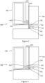
- the system shown in Figure 2 shows the aerosol-generating system 500 with the first component 100 of the cartridge 300 in the second position.
- the aerosol-forming substrate outlet 120 and the aerosol-forming substrate inlet 220 are aligned with one another so that the aerosol-forming substrate can pass from the first component 100 to the second component 200.
- the system is configured so that a user can puff or suck on the first air outlet 145 of the cartridge 300 to draw aerosol into their mouth.
- air is drawn through the second airflow channel from the second air inlet 240, past the aerosol-generating element 230, to the first air inlet 140 and through the first airflow channel to the first air outlet 145.
- the control circuitry 420 controls the supply of electrical power from the battery 410 to the cartridge 300 when the system is activated. This in turn controls the amount and properties of the vapour produced by the aerosol-generating element 230.
- the control circuitry 420 may include an airflow sensor and the control circuitry may supply electrical power to the aerosol-generating element 230 when user puffs on the cartridge 300 are detected by the airflow sensor.
- the aerosol-generating element 230 When a user sucks on the first air outlet 145 of the cartridge 300, the aerosol-generating element 230 is activated and generates a vapour that is entrained in the airflow passing through the first and second airflow channels. The vapour cools to form an aerosol, which is then drawn into the user's mouth through the first air outlet 145.
- the user may translate the first component 100 from the second position back to the first position, relative to the second component 200.
- the sliding mechanism 150 may be configured to allow the first component 100 to be translated relative to the second component 200 in a single direction.
- Figure 3 illustrates a cross-sectional view of a cartridge 800 of a second embodiment of the invention that comprises a longitudinally arranged sliding mechanism 650, with a first component 600 of the cartridge 800 in a first position.
- the cartridge 800 illustrated in Figure 3 includes an aerosol-forming substrate outlet 620 and an aerosol-forming substrate inlet 720 formed on opposing parallel walls of a first 600 and a second 700 component, respectively.
- the outlet 620 is not aligned with the inlet 720 and in the second position the outlet 620 is aligned with the inlet 720 along an axis perpendicular to the parallel walls.
- the sliding mechanism 650 is configured to allow the first component to translate only in a lateral direction orthogonal to the axis perpendicular to the parallel walls.
- the parallel walls are parallel to a longitudinal axis of a first airflow channel. Therefore, the sliding mechanism illustrated in Figure 3 is configured to translate the first component in a direction parallel to the longitudinal axis of the first airflow channel.
- Figure 4 illustrates the cartridge 800 with a longitudinal sliding mechanism 650, with the first component 600 of the cartridge 800 in the second position.
- the aerosol-forming substrate outlet 620 and the aerosol-forming substrate inlet 720 are aligned with one another so that the aerosol-forming substrate can pass between the first component 600 and the second component 700.
- the aerosol-generating system operates in substantially the same way as the first embodiment.
- the user translates the first component 600 from the first position to the second position, relative to the second component 700, and then connects the cartridge 800 to a control body.
- the user puffs on the first air outlet 645.
- the aerosol-generating element 730 is activated and generates a vapour of the aerosol-forming substrate.
- the vapour is entrained in the airflow passing from the second air inlet 740 through the first and second airflow channels. In the airflow channels the vapour cools to form an aerosol, which is then drawn into the user's mouth through the first air outlet 645.
- the user may translate the first component 600 from the second position back to the first position, relative to the second component 700.
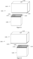
- Figure 5 illustrates an exploded three-dimensional view of a cartridge 1300 of a third embodiment of the invention, with a first component 1100 of the cartridge 1300 in a first position.
- Figure 5 illustrates an alternative airflow channel and aerosol-forming substrate inlet 1220 arrangement to that illustrated in Figure 1 .
- the configuration of a first air inlet 1140, first air outlet 1145, second air inlet 1240 and second air outlet 1245, relative to the aerosol-forming substrate outlet 1120 and the aerosol-forming substrate inlet 1220 is different in the cartridge 1300 of Figure 5 compared to the cartridge of Figure 1 .
- the second air outlet 1245 is adjacent to the aerosol-forming substrate inlet 1220 in a direction perpendicular to the direction in which the sliding mechanism 1150 is configured to allow the first component 1100 to translate, relative to the second component 1200.
- Figure 5 shows the second component 1200 comprising elastomer sheet sealing element 1210 configured to prevent leakage of aerosol-forming substrate from the first component 1100 when the first component 1100 is not in the second position.
- Figure 6 illustrates an exploded three-dimensional view of the cartridge 1300 of Figure 5 , with the first component 1100 of the cartridge 1300 in the second position.
- Figure 7a illustrates a bottom view of the first component 1100 of Figures 5 and 6 .
- Figure 7a illustrates the first air inlet 1140 is adjacent to the aerosol-forming substrate outlet 1120 in a direction perpendicular to the direction in which the sliding mechanism 1150 is configured to allow the first component 1100 to translate, relative to the second component 1200.
- Ribs 1130 surround, and are in-between, the first air inlet 1140 and the first substrate outlet 1120.
- Figure 7b illustrates a top view of the second component of Figures 5 and 6 .
- Figure 7b illustrates the second air outlet 1245 and the aerosol-forming substrate inlet 1220.
- the substantially flat elastomer sheet sealing element 1210 is fixed to the second component 1200.
- the sealing element 1210 When the cartridge is assembled and the first component 1100 is in the first position, the sealing element 1210 interacts with the ribs 1130 of the first component. The ribs 1130 press against the sealing element 1210. This seals the first air inlet 1140 and the aerosol-forming substrate outlet 1120 so that fluid cannot pass between the first component 1100 and the second component 1200, or between the first air inlet 1140 and the aerosol-forming substrate outlet 1120.
- the aerosol-forming substrate outlet 1120 is aligned with the first opening in the sealing element 1210 over the aerosol-forming substrate inlet 1220.
- the first air inlet 1140 is aligned with the second opening in the sealing element 1210 over the second air outlet 1245.
- aerosol-forming substrate can pass between the first components 1100 the second component 1200.
- the rib situated between the aerosol-forming substrate outlet 1120 and the first air inlet 1140 presses against the sealing element 1210 between the first opening in the sealing element and the second opening in the sealing element. This prevents fluid passing directly between the first air inlet 1140 and the aerosol-forming substrate outlet when 1120 when the first component 1100 is in the first position or in the second position.
- Figure 8 illustrates a schematic cross-sectional view of the cartridge 1300 of Figure 6 .
- the second air outlet 1245 is adjacent to the aerosol-forming substrate inlet 1220 in a direction perpendicular to the direction in which the sliding mechanism 1150 is configured to allow the first component 1100 to translate, relative to the second component 1200.
- the first air inlet 1140 is adjacent to the aerosol-forming substrate outlet 1120 in a direction perpendicular to the direction in which the sliding mechanism 1150 is configured to allow the first component 1100 to translate, relative to the second component 1200.
- the second air inlet 1240 is configured for air to enter the second airflow channel in a direction perpendicular to the direction in which air exits the second airflow channel through the second air outlet 1245.
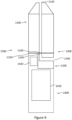
- FIG. 9 illustrates a schematic cross-sectional view of an aerosol-generating system 1500 of the third embodiment of the invention.
- the aerosol-generating system 1500 of Figure 9 shows the first component 1100 of the cartridge in the second position relative to the second component 1200.
- the cartridge 1300 is connected to the control body 1400.
- the second component 1200 of the cartridge 1300 is substantially received within a cavity in the control body 1400.
- the control body 1400 comprises a battery 1410, and a controller 1420 electrically connected to the battery 1410.
- the battery 1410 is configured to provide power to the cartridge 1300 via an electrical connection. This electrical connection is a wired connection and is not shown in Figure 9 .
- the aerosol-generating system operates in substantially the same way as the first embodiment.
- the user via the sliding mechanism 1150, translates the first component 1100 from the first position to the second position, relative to the second component 1200, and then connects the cartridge 1300 to a control body. Subsequently, the user puffs on the first air outlet 1145.
- the aerosol-generating element 1230 is activated, vaporising the aerosol-forming substrate.
- the vapour is entrained in the airflow passing from the second air inlet 1240 through the first and second airflow channels. The vapour cools to form an aerosol, which is drawn into the user's mouth through the first air outlet 1145.
Landscapes
- Health & Medical Sciences (AREA)
- Engineering & Computer Science (AREA)
- Anesthesiology (AREA)
- Biomedical Technology (AREA)
- Heart & Thoracic Surgery (AREA)
- Hematology (AREA)
- Life Sciences & Earth Sciences (AREA)
- Animal Behavior & Ethology (AREA)
- General Health & Medical Sciences (AREA)
- Public Health (AREA)
- Veterinary Medicine (AREA)
- Bioinformatics & Cheminformatics (AREA)
- Pulmonology (AREA)
- Catching Or Destruction (AREA)
- Containers And Packaging Bodies Having A Special Means To Remove Contents (AREA)
Claims (15)
- Patrone (300, 800, 1300) für ein Aerosolerzeugungssystem (500, 1500), die Patrone (300, 800, 1300) umfassend:eine erste Komponente (100, 600, 1100), umfassend einen Vorratsbehälter (105), der aerosolbildendes Substrat aufnimmt, und einen Auslass für das aerosolbildende Substrat (120, 620, 1120);eine zweite Komponente (200, 700, 1200), umfassend einen Einlass für ein aerosolbildendes Substrat (220, 720, 1220) und ein aerosolerzeugendes Element (230, 730, 1230); undeinen Gleitmechanismus (150, 650, 1150), der die erste Komponente (100, 600, 1100) mit der zweiten Komponente (200, 700, 1200) verbindet und dazu eingerichtet ist, um der ersten Komponente (100, 600, 1100) zu ermöglichen, sich von einer ersten Position in eine zweite Position in Bezug auf die zweite Komponente (200, 700, 1200) zu verlagern;wobei in der ersten Position der Auslass (120, 620, 1120) für das aerosolbildende Substrat und der Einlass (220, 720, 1220) für das aerosolbildende Substrat nicht miteinander ausgerichtet sind, sodass das aerosolbildende Substrat nicht von der ersten Komponente (100, 600, 1100) zu der zweiten Komponente (200, 700, 1200) passieren kann, und in der zweiten Position der Auslass (120, 620, 1120) für das aerosolbildende Substrat und der Einlass (220, 720, 1220) für das aerosolbildende Substrat miteinander ausgerichtet sind, sodass das aerosolbildende Substrat von der ersten Komponente (100, 600, 1100) zu der zweiten Komponente (200, 700, 1200) passieren kann.
- Patrone (300, 800, 1300) nach Anspruch 1, wobei der Auslass (120, 620, 1120) für das aerosolbildende Substrat und der Einlass (220, 720, 1220) für das aerosolbildende Substrat an gegenüberliegenden parallelen Wänden jeweils der ersten und zweiten Komponente gebildet sind, und wobei in der ersten Position der Auslass (120, 620, 1120) nicht mit dem Einlass (220, 720, 1220) ausgerichtet ist und in der zweiten Position der Auslass (120, 620, 1120) mit dem Einlass (220, 720, 1220) entlang einer Achse senkrecht zu den parallelen Wänden ausgerichtet ist.
- Patrone (300, 800, 1300) nach Anspruch 2, wobei der Gleitmechanismus (150, 650, 1150) dazu eingerichtet ist, um der ersten Komponente (100, 600, 1100) zu ermöglichen, sich nur in einer seitlichen Richtung orthogonal zu der Achse senkrecht zu den parallelen Wänden zu verlagern.
- Patrone (300, 800, 1300) nach einem beliebigen vorhergehenden Anspruch, wobei in der ersten Position der Auslass (120, 620, 1120) für das aerosolbildende Substrat durch die zweite Komponente (200, 700, 1200) abgedichtet ist.
- Patrone (300, 800, 1300) nach einem beliebigen vorhergehenden Anspruch, wobei die erste Komponente (100, 600, 1100) ferner einen ersten Luftstromkanal umfasst, der einen ersten Lufteinlass (140, 640, 1140) und einen ersten Luftauslass (145, 645, 1145) umfasst; und die zweite Komponente (200, 700, 1200) ferner einen zweiten Luftstromkanal umfasst, der einen zweiten Lufteinlass (240, 740, 1240) und einen zweiten Luftauslass (245, 745, 1245) umfasst.
- Patrone (300, 800, 1300) nach Anspruch 5, wobei in der ersten Position der erste Lufteinlass (140, 640, 1140) und der zweite Luftauslass (245, 745, 1245) nicht miteinander ausgerichtet sind, sodass Luft nicht zwischen dem zweiten Luftstromkanal und dem ersten Luftstromkanal passieren kann, und in der zweiten Position der erste Lufteinlass (140, 640, 1140) und der zweite Luftauslass (245, 745, 1245) miteinander ausgerichtet sind, sodass Luft zwischen dem zweiten Luftstromkanal und dem ersten Luftstromkanal passieren kann.
- Patrone (300, 800, 1300) nach Anspruch 5 oder 6, wobei der Gleitmechanismus (150, 650, 1150) dazu eingerichtet ist, der ersten Komponente (100, 600, 1100) zu ermöglichen, sich in einer seitlichen Richtung in Bezug auf eine Längsachse des ersten Luftstromkanals zu verlagern.
- Patrone (300, 800, 1300) nach einem beliebigen vorhergehenden Anspruch, ferner umfassend ein zerbrechliches Element, das mit der ersten Komponente (100, 600, 1100) und der zweiten Komponente (200, 700, 1200) gekoppelt und dazu eingerichtet ist, zu zerbrechen, wenn die erste Komponente aus der ersten Position bewegt wird.
- Patrone (300, 800, 1300) nach einem beliebigen vorhergehenden Anspruch, wobei der Gleitmechanismus dazu eingerichtet ist, der ersten Komponente (100, 600, 1100) zu ermöglichen, in Bezug auf die zweite Komponente in einer einzigen Richtung verlagert zu werden.
- Patrone (300, 800, 1300) nach einem beliebigen vorhergehenden Anspruch, ferner umfassend einen Verriegelungsmechanismus, der die erste Komponente (100, 600, 1100) in der zweiten Position zurückhält.
- Patrone nach einem beliebigen vorhergehenden Anspruch, wobei die zweite Komponente (200, 700, 1200) ferner ein Kapillarmaterial (250, 750, 1250) angrenzend an das aerosolerzeugende Element (230, 730, 1230) umfasst.
- Patrone (300, 800, 1300) nach einem beliebigen vorhergehenden Anspruch, wobei das aerosolerzeugende Element (230, 730, 1230) ein fluiddurchlässiges Netz umfasst.
- Eine Patrone (300, 1300) nach einem beliebigen vorhergehenden Anspruch, ferner umfassend ein Mundstück (115).
- Aerosolerzeugungssystem (500, 1000), umfassend: eine Patrone (300, 800, 1300) nach einem beliebigen vorhergehenden Anspruch und einen mit der Patrone (300, 800, 1300) verbundenen Regelkörper (400, 1400), wobei der Regelkörper (400, 1400) eine Energieversorgung umfasst, die dazu eingerichtet ist, das aerosolerzeugende Element (230, 730, 1230) mit Energie zu versorgen.
- Aerosolerzeugungssystem (500, 1000) nach Anspruch 14, wobei der Regelkörper (400, 1400) direkt mit der zweiten Komponente (200, 700, 1200) verbunden ist.
Applications Claiming Priority (2)
| Application Number | Priority Date | Filing Date | Title |
|---|---|---|---|
| EP21186259 | 2021-07-16 | ||
| PCT/EP2022/069792 WO2023285618A1 (en) | 2021-07-16 | 2022-07-14 | Aerosol-generating system and cartridge for aerosol-generating system with sliding mechanism for mechanical sealing |
Publications (3)
| Publication Number | Publication Date |
|---|---|
| EP4369959A1 EP4369959A1 (de) | 2024-05-22 |
| EP4369959B1 true EP4369959B1 (de) | 2025-03-12 |
| EP4369959C0 EP4369959C0 (de) | 2025-03-12 |
Family
ID=76958892
Family Applications (1)
| Application Number | Title | Priority Date | Filing Date |
|---|---|---|---|
| EP22737513.6A Active EP4369959B1 (de) | 2021-07-16 | 2022-07-14 | Aerosolerzeugendes system und kartusche für ein aerosolerzeugendes system mit gleitmechanismus zur mechanischen abdichtung |
Country Status (6)
| Country | Link |
|---|---|
| US (1) | US20240292890A1 (de) |
| EP (1) | EP4369959B1 (de) |
| JP (1) | JP2024525645A (de) |
| KR (1) | KR20240034801A (de) |
| CN (1) | CN117615675A (de) |
| WO (1) | WO2023285618A1 (de) |
Families Citing this family (1)
| Publication number | Priority date | Publication date | Assignee | Title |
|---|---|---|---|---|
| US10165799B2 (en) * | 2015-11-17 | 2019-01-01 | Altria Client Services Llc | Aerosol-generating system with self-activated electric heater |
Family Cites Families (5)
| Publication number | Priority date | Publication date | Assignee | Title |
|---|---|---|---|---|
| JP6719470B2 (ja) * | 2014-12-18 | 2020-07-08 | ジェイティー インターナショナル エス.エイ. | エアロゾル発生装置用の容器 |
| EP3292771B1 (de) * | 2016-09-06 | 2018-11-21 | Fontem Holdings 2 B.V. | Gehäuse für eine elektronische rauchvorrichtung mit einem ersten und einem zweiten flügelelement |
| WO2018111843A1 (en) * | 2016-12-12 | 2018-06-21 | Vmr Products Llc | Vaporizer cartridge |
| GB2576712B (en) * | 2018-08-23 | 2022-06-01 | All Vape Ltd | A pod |
| UA129289C2 (uk) * | 2018-12-07 | 2025-03-12 | Філіп Морріс Продактс С.А. | Система, що генерує аерозоль, та спосіб генерування аерозолю |
-
2022
- 2022-07-14 US US18/578,495 patent/US20240292890A1/en active Pending
- 2022-07-14 WO PCT/EP2022/069792 patent/WO2023285618A1/en not_active Ceased
- 2022-07-14 KR KR1020247004931A patent/KR20240034801A/ko active Pending
- 2022-07-14 EP EP22737513.6A patent/EP4369959B1/de active Active
- 2022-07-14 CN CN202280048292.9A patent/CN117615675A/zh active Pending
- 2022-07-14 JP JP2024500646A patent/JP2024525645A/ja active Pending
Also Published As
| Publication number | Publication date |
|---|---|
| JP2024525645A (ja) | 2024-07-12 |
| KR20240034801A (ko) | 2024-03-14 |
| EP4369959A1 (de) | 2024-05-22 |
| EP4369959C0 (de) | 2025-03-12 |
| CN117615675A (zh) | 2024-02-27 |
| US20240292890A1 (en) | 2024-09-05 |
| WO2023285618A1 (en) | 2023-01-19 |
Similar Documents
| Publication | Publication Date | Title |
|---|---|---|
| US12514293B2 (en) | Heater assembly having heater element isolated from liquid supply | |
| EP3890529B1 (de) | Aerosolerzeugungssystem und -kartusche mit leckageschutz | |
| US11375749B2 (en) | Adaptable aerosol-generating system | |
| EP3288403B1 (de) | Kartusche für ein aerosolerzeugungssystem | |
| EP3890530B1 (de) | Aerosolerzeugungssystem und -kartusche mit leckageschutz | |
| US20250143373A1 (en) | Aerosol-generating system providing preferential evaporation of nicotine | |
| US20220015434A1 (en) | An atomiser and an aerosol-generating system comprising an atomiser | |
| US12256780B2 (en) | Cartridge for an aerosol-generating system, an aerosol-generating system including a cartridge, and a method of manufacturing a heater assembly and cartridge for an aerosol-generating system | |
| IL263374A (en) | Cartridge for spray system with heater protection | |
| EP3104722A1 (de) | Kartusche mit einer heizanordnung für ein aerosolerzeugungssystem | |
| US12161165B2 (en) | Aerosol-generating system and cartridge with leakage protection | |
| EP4266923B1 (de) | Heizeranordnung | |
| EP4369959B1 (de) | Aerosolerzeugendes system und kartusche für ein aerosolerzeugendes system mit gleitmechanismus zur mechanischen abdichtung | |
| EP4444120B1 (de) | Hybrides aerosolerzeugungssystem mit modularem verbrauchsmaterial | |
| EP4518704B1 (de) | Aerosolerzeugungsvorrichtung und heizungsanordnung | |
| RU2846608C2 (ru) | Система для генерирования аэрозоля и картридж для системы для генерирования аэрозоля с механизмом для скольжения для механического уплотнения | |
| HK40005075A (en) | Cartridge for an aerosol-generating system with heater protection | |
| HK1251129B (en) | Cartridge for an aerosol-generating system |
Legal Events
| Date | Code | Title | Description |
|---|---|---|---|
| STAA | Information on the status of an ep patent application or granted ep patent |
Free format text: STATUS: UNKNOWN |
|
| STAA | Information on the status of an ep patent application or granted ep patent |
Free format text: STATUS: THE INTERNATIONAL PUBLICATION HAS BEEN MADE |
|
| PUAI | Public reference made under article 153(3) epc to a published international application that has entered the european phase |
Free format text: ORIGINAL CODE: 0009012 |
|
| STAA | Information on the status of an ep patent application or granted ep patent |
Free format text: STATUS: REQUEST FOR EXAMINATION WAS MADE |
|
| 17P | Request for examination filed |
Effective date: 20240126 |
|
| AK | Designated contracting states |
Kind code of ref document: A1 Designated state(s): AL AT BE BG CH CY CZ DE DK EE ES FI FR GB GR HR HU IE IS IT LI LT LU LV MC MK MT NL NO PL PT RO RS SE SI SK SM TR |
|
| REG | Reference to a national code |
Free format text: PREVIOUS MAIN CLASS: A24F0040420000 Ipc: A24F0040400000 Ref country code: DE Ref legal event code: R079 Ref document number: 602022011770 Country of ref document: DE Free format text: PREVIOUS MAIN CLASS: A24F0040420000 Ipc: A24F0040400000 |
|
| DAV | Request for validation of the european patent (deleted) | ||
| DAX | Request for extension of the european patent (deleted) | ||
| GRAP | Despatch of communication of intention to grant a patent |
Free format text: ORIGINAL CODE: EPIDOSNIGR1 |
|
| STAA | Information on the status of an ep patent application or granted ep patent |
Free format text: STATUS: GRANT OF PATENT IS INTENDED |
|
| RIC1 | Information provided on ipc code assigned before grant |
Ipc: A24F 40/10 20200101ALN20241010BHEP Ipc: H05B 3/42 20060101ALI20241010BHEP Ipc: H05B 3/04 20060101ALI20241010BHEP Ipc: A61M 15/06 20060101ALI20241010BHEP Ipc: A61M 11/04 20060101ALI20241010BHEP Ipc: A24F 40/485 20200101ALI20241010BHEP Ipc: A24F 40/42 20200101ALI20241010BHEP Ipc: A24F 40/40 20200101AFI20241010BHEP |
|
| INTG | Intention to grant announced |
Effective date: 20241104 |
|
| GRAS | Grant fee paid |
Free format text: ORIGINAL CODE: EPIDOSNIGR3 |
|
| GRAA | (expected) grant |
Free format text: ORIGINAL CODE: 0009210 |
|
| STAA | Information on the status of an ep patent application or granted ep patent |
Free format text: STATUS: THE PATENT HAS BEEN GRANTED |
|
| AK | Designated contracting states |
Kind code of ref document: B1 Designated state(s): AL AT BE BG CH CY CZ DE DK EE ES FI FR GB GR HR HU IE IS IT LI LT LU LV MC MK MT NL NO PL PT RO RS SE SI SK SM TR |
|
| REG | Reference to a national code |
Ref country code: GB Ref legal event code: FG4D |
|
| REG | Reference to a national code |
Ref country code: CH Ref legal event code: EP |
|
| REG | Reference to a national code |
Ref country code: DE Ref legal event code: R096 Ref document number: 602022011770 Country of ref document: DE |
|
| REG | Reference to a national code |
Ref country code: IE Ref legal event code: FG4D |
|
| U01 | Request for unitary effect filed |
Effective date: 20250312 |
|
| U07 | Unitary effect registered |
Designated state(s): AT BE BG DE DK EE FI FR IT LT LU LV MT NL PT RO SE SI Effective date: 20250318 |
|
| PG25 | Lapsed in a contracting state [announced via postgrant information from national office to epo] |
Ref country code: RS Free format text: LAPSE BECAUSE OF FAILURE TO SUBMIT A TRANSLATION OF THE DESCRIPTION OR TO PAY THE FEE WITHIN THE PRESCRIBED TIME-LIMIT Effective date: 20250612 |
|
| PG25 | Lapsed in a contracting state [announced via postgrant information from national office to epo] |
Ref country code: ES Free format text: LAPSE BECAUSE OF FAILURE TO SUBMIT A TRANSLATION OF THE DESCRIPTION OR TO PAY THE FEE WITHIN THE PRESCRIBED TIME-LIMIT Effective date: 20250312 |
|
| PG25 | Lapsed in a contracting state [announced via postgrant information from national office to epo] |
Ref country code: NO Free format text: LAPSE BECAUSE OF FAILURE TO SUBMIT A TRANSLATION OF THE DESCRIPTION OR TO PAY THE FEE WITHIN THE PRESCRIBED TIME-LIMIT Effective date: 20250612 |
|
| PG25 | Lapsed in a contracting state [announced via postgrant information from national office to epo] |
Ref country code: HR Free format text: LAPSE BECAUSE OF FAILURE TO SUBMIT A TRANSLATION OF THE DESCRIPTION OR TO PAY THE FEE WITHIN THE PRESCRIBED TIME-LIMIT Effective date: 20250312 |
|
| PG25 | Lapsed in a contracting state [announced via postgrant information from national office to epo] |
Ref country code: GR Free format text: LAPSE BECAUSE OF FAILURE TO SUBMIT A TRANSLATION OF THE DESCRIPTION OR TO PAY THE FEE WITHIN THE PRESCRIBED TIME-LIMIT Effective date: 20250613 |
|
| U20 | Renewal fee for the european patent with unitary effect paid |
Year of fee payment: 4 Effective date: 20250728 |
|
| PG25 | Lapsed in a contracting state [announced via postgrant information from national office to epo] |
Ref country code: SM Free format text: LAPSE BECAUSE OF FAILURE TO SUBMIT A TRANSLATION OF THE DESCRIPTION OR TO PAY THE FEE WITHIN THE PRESCRIBED TIME-LIMIT Effective date: 20250312 |
|
| PG25 | Lapsed in a contracting state [announced via postgrant information from national office to epo] |
Ref country code: PL Free format text: LAPSE BECAUSE OF FAILURE TO SUBMIT A TRANSLATION OF THE DESCRIPTION OR TO PAY THE FEE WITHIN THE PRESCRIBED TIME-LIMIT Effective date: 20250312 |
|
| PGFP | Annual fee paid to national office [announced via postgrant information from national office to epo] |
Ref country code: CH Payment date: 20250801 Year of fee payment: 4 |
|
| PG25 | Lapsed in a contracting state [announced via postgrant information from national office to epo] |
Ref country code: CZ Free format text: LAPSE BECAUSE OF FAILURE TO SUBMIT A TRANSLATION OF THE DESCRIPTION OR TO PAY THE FEE WITHIN THE PRESCRIBED TIME-LIMIT Effective date: 20250312 |
|
| PG25 | Lapsed in a contracting state [announced via postgrant information from national office to epo] |
Ref country code: SK Free format text: LAPSE BECAUSE OF FAILURE TO SUBMIT A TRANSLATION OF THE DESCRIPTION OR TO PAY THE FEE WITHIN THE PRESCRIBED TIME-LIMIT Effective date: 20250312 |
|
| PG25 | Lapsed in a contracting state [announced via postgrant information from national office to epo] |
Ref country code: IS Free format text: LAPSE BECAUSE OF FAILURE TO SUBMIT A TRANSLATION OF THE DESCRIPTION OR TO PAY THE FEE WITHIN THE PRESCRIBED TIME-LIMIT Effective date: 20250712 |
|
| PLBE | No opposition filed within time limit |
Free format text: ORIGINAL CODE: 0009261 |
|
| STAA | Information on the status of an ep patent application or granted ep patent |
Free format text: STATUS: NO OPPOSITION FILED WITHIN TIME LIMIT |
|
| REG | Reference to a national code |
Ref country code: CH Ref legal event code: L10 Free format text: ST27 STATUS EVENT CODE: U-0-0-L10-L00 (AS PROVIDED BY THE NATIONAL OFFICE) Effective date: 20260121 |
|
| 26N | No opposition filed |
Effective date: 20251215 |