EP4369549A1 - Flexible direct-current traction power supply system connected with distributed external power supplies, and operating method therefor - Google Patents
Flexible direct-current traction power supply system connected with distributed external power supplies, and operating method therefor Download PDFInfo
- Publication number
- EP4369549A1 EP4369549A1 EP21949126.3A EP21949126A EP4369549A1 EP 4369549 A1 EP4369549 A1 EP 4369549A1 EP 21949126 A EP21949126 A EP 21949126A EP 4369549 A1 EP4369549 A1 EP 4369549A1
- Authority
- EP
- European Patent Office
- Prior art keywords
- power
- flexible direct
- busbar
- traction
- current traction
- Prior art date
- Legal status (The legal status is an assumption and is not a legal conclusion. Google has not performed a legal analysis and makes no representation as to the accuracy of the status listed.)
- Pending
Links
Images




Classifications
-
- H—ELECTRICITY
- H02—GENERATION; CONVERSION OR DISTRIBUTION OF ELECTRIC POWER
- H02J—ELECTRIC POWER NETWORKS; CIRCUIT ARRANGEMENTS OR SYSTEMS FOR SUPPLYING OR DISTRIBUTING ELECTRIC POWER; SYSTEMS FOR STORING ELECTRIC ENERGY
- H02J3/00—Circuit arrangements for AC mains or AC distribution networks
- H02J3/36—Arrangements for transfer of electric power between AC networks via high-voltage DC [HVDC] links; Arrangements for transfer of electric power between generators and networks via HVDC links
-
- B—PERFORMING OPERATIONS; TRANSPORTING
- B60—VEHICLES IN GENERAL
- B60M—POWER SUPPLY LINES, AND DEVICES ALONG RAILS, FOR ELECTRICALLY- PROPELLED VEHICLES
- B60M3/00—Feeding power to supply lines in contact with collector on vehicles; Arrangements for consuming regenerative power
-
- B—PERFORMING OPERATIONS; TRANSPORTING
- B60—VEHICLES IN GENERAL
- B60M—POWER SUPPLY LINES, AND DEVICES ALONG RAILS, FOR ELECTRICALLY- PROPELLED VEHICLES
- B60M3/00—Feeding power to supply lines in contact with collector on vehicles; Arrangements for consuming regenerative power
- B60M3/06—Arrangements for consuming regenerative power
-
- H—ELECTRICITY
- H02—GENERATION; CONVERSION OR DISTRIBUTION OF ELECTRIC POWER
- H02J—ELECTRIC POWER NETWORKS; CIRCUIT ARRANGEMENTS OR SYSTEMS FOR SUPPLYING OR DISTRIBUTING ELECTRIC POWER; SYSTEMS FOR STORING ELECTRIC ENERGY
- H02J1/00—Circuit arrangements for DC mains or DC distribution networks
- H02J1/08—Three-wire DC power distribution systems; Systems having more than three wires
- H02J1/084—Three-wire DC power distribution systems; Systems having more than three wires for selectively connecting the load or loads to one or several among a plurality of power lines or power sources
- H02J1/086—Three-wire DC power distribution systems; Systems having more than three wires for selectively connecting the load or loads to one or several among a plurality of power lines or power sources for providing alternative feeding paths between load or loads and source or sources when the main path fails
-
- H—ELECTRICITY
- H02—GENERATION; CONVERSION OR DISTRIBUTION OF ELECTRIC POWER
- H02J—ELECTRIC POWER NETWORKS; CIRCUIT ARRANGEMENTS OR SYSTEMS FOR SUPPLYING OR DISTRIBUTING ELECTRIC POWER; SYSTEMS FOR STORING ELECTRIC ENERGY
- H02J1/00—Circuit arrangements for DC mains or DC distribution networks
- H02J1/10—Parallel operation of DC sources
- H02J1/102—Parallel operation of DC sources being switching converters
-
- H—ELECTRICITY
- H02—GENERATION; CONVERSION OR DISTRIBUTION OF ELECTRIC POWER
- H02J—ELECTRIC POWER NETWORKS; CIRCUIT ARRANGEMENTS OR SYSTEMS FOR SUPPLYING OR DISTRIBUTING ELECTRIC POWER; SYSTEMS FOR STORING ELECTRIC ENERGY
- H02J3/00—Circuit arrangements for AC mains or AC distribution networks
- H02J3/001—Arrangements for handling faults or abnormalities, e.g. emergencies or contingencies
-
- H—ELECTRICITY
- H02—GENERATION; CONVERSION OR DISTRIBUTION OF ELECTRIC POWER
- H02J—ELECTRIC POWER NETWORKS; CIRCUIT ARRANGEMENTS OR SYSTEMS FOR SUPPLYING OR DISTRIBUTING ELECTRIC POWER; SYSTEMS FOR STORING ELECTRIC ENERGY
- H02J3/00—Circuit arrangements for AC mains or AC distribution networks
- H02J3/001—Arrangements for handling faults or abnormalities, e.g. emergencies or contingencies
- H02J3/0014—Arrangements for handling faults or abnormalities, e.g. emergencies or contingencies for preventing or reducing power oscillations in networks
-
- H—ELECTRICITY
- H02—GENERATION; CONVERSION OR DISTRIBUTION OF ELECTRIC POWER
- H02J—ELECTRIC POWER NETWORKS; CIRCUIT ARRANGEMENTS OR SYSTEMS FOR SUPPLYING OR DISTRIBUTING ELECTRIC POWER; SYSTEMS FOR STORING ELECTRIC ENERGY
- H02J3/00—Circuit arrangements for AC mains or AC distribution networks
- H02J3/007—Arrangements for selectively connecting one or more loads to one or more power sources or power lines
- H02J3/0073—Arrangements for selectively connecting one or more loads to one or more power sources or power lines by providing alternative feeding paths when the main path fails
-
- H—ELECTRICITY
- H02—GENERATION; CONVERSION OR DISTRIBUTION OF ELECTRIC POWER
- H02J—ELECTRIC POWER NETWORKS; CIRCUIT ARRANGEMENTS OR SYSTEMS FOR SUPPLYING OR DISTRIBUTING ELECTRIC POWER; SYSTEMS FOR STORING ELECTRIC ENERGY
- H02J3/00—Circuit arrangements for AC mains or AC distribution networks
- H02J3/04—Arrangements for connecting networks of the same frequency but supplied from different sources
- H02J3/06—Controlling the transfer of power between connected networks; Controlling load sharing between connected networks
-
- H—ELECTRICITY
- H02—GENERATION; CONVERSION OR DISTRIBUTION OF ELECTRIC POWER
- H02J—ELECTRIC POWER NETWORKS; CIRCUIT ARRANGEMENTS OR SYSTEMS FOR SUPPLYING OR DISTRIBUTING ELECTRIC POWER; SYSTEMS FOR STORING ELECTRIC ENERGY
- H02J3/00—Circuit arrangements for AC mains or AC distribution networks
- H02J3/26—Arrangements for eliminating or reducing asymmetry in polyphase networks
-
- H—ELECTRICITY
- H02—GENERATION; CONVERSION OR DISTRIBUTION OF ELECTRIC POWER
- H02J—ELECTRIC POWER NETWORKS; CIRCUIT ARRANGEMENTS OR SYSTEMS FOR SUPPLYING OR DISTRIBUTING ELECTRIC POWER; SYSTEMS FOR STORING ELECTRIC ENERGY
- H02J3/00—Circuit arrangements for AC mains or AC distribution networks
- H02J3/38—Arrangements for feeding a single network from two or more generators or sources in parallel; Arrangements for feeding already energised networks from additional generators or sources in parallel
-
- Y—GENERAL TAGGING OF NEW TECHNOLOGICAL DEVELOPMENTS; GENERAL TAGGING OF CROSS-SECTIONAL TECHNOLOGIES SPANNING OVER SEVERAL SECTIONS OF THE IPC; TECHNICAL SUBJECTS COVERED BY FORMER USPC CROSS-REFERENCE ART COLLECTIONS [XRACs] AND DIGESTS
- Y02—TECHNOLOGIES OR APPLICATIONS FOR MITIGATION OR ADAPTATION AGAINST CLIMATE CHANGE
- Y02E—REDUCTION OF GREENHOUSE GAS [GHG] EMISSIONS, RELATED TO ENERGY GENERATION, TRANSMISSION OR DISTRIBUTION
- Y02E40/00—Technologies for an efficient electrical power generation, transmission or distribution
- Y02E40/50—Arrangements for eliminating or reducing asymmetry in polyphase networks
-
- Y—GENERAL TAGGING OF NEW TECHNOLOGICAL DEVELOPMENTS; GENERAL TAGGING OF CROSS-SECTIONAL TECHNOLOGIES SPANNING OVER SEVERAL SECTIONS OF THE IPC; TECHNICAL SUBJECTS COVERED BY FORMER USPC CROSS-REFERENCE ART COLLECTIONS [XRACs] AND DIGESTS
- Y02—TECHNOLOGIES OR APPLICATIONS FOR MITIGATION OR ADAPTATION AGAINST CLIMATE CHANGE
- Y02E—REDUCTION OF GREENHOUSE GAS [GHG] EMISSIONS, RELATED TO ENERGY GENERATION, TRANSMISSION OR DISTRIBUTION
- Y02E60/00—Enabling technologies; Technologies with a potential or indirect contribution to GHG emissions mitigation
- Y02E60/60—Arrangements for transfer of electric power between AC networks or generators via a high voltage DC link [HVCD]
Definitions
- the present disclosure relates to the field of flexible direct-current traction power supply technologies, and more particularly, to a flexible direct-current traction power supply system connected to a distributed external power source and an operation method thereof.
- the flexible direct-current traction power supply technology may overcome the defects of a diode rectification power supply scheme and an energy-feedback-type power supply scheme to a great extent, making it a future development trend.
- the requirements for power supply capacity and distance of a direct-current traction power supply system increase accordingly.
- a low utilization rate of redundancy capacity of a traction substation, too large energy consumption, or the like in a traditional direct-current traction power supply system it is necessary to study a flexible direct-current traction power supply scheme.
- the present disclosure aims to solve at least one of the technical problems in the related art to some extent.
- an object of the present disclosure is to provide a flexible direct-current traction power supply system connected to a distributed external power source, which is capable of lowering the demand for an external power source in the flexible direct-current traction power supply system and enhancing a capacity utilization rate of a traction substation device and a utilization rate of locomotive regenerative braking energy, allowing to conserve energy and carbon and control power quality of an alternating-current and direct-current system, thereby bringing numerous advantages to the traction power supply system.
- a technical scheme may be provided for practical engineering of flexible direct-current traction power supply technology in rail transit.
- Another object of the present disclosure is to provide a method for operating a flexible direct-current traction power supply system connected to a distributed external power source.
- an embodiment in an aspect of the present disclosure provides a flexible direct-current traction power supply system connected to a distributed external power source, including: a plurality of flexible direct-current traction substations.
- Each of the plurality of flexible direct-current traction substations includes: a first incoming power line and a second incoming power line that are connected to an external power source; a first power busbar connected to the first incoming power line through a circuit breaker, and a second power busbar connected to the second incoming power line through a circuit breaker; a first traction transformer having one end connected to the first power busbar through a circuit breaker and another end connected to an alternating current side of a first bidirectional converter, the first bidirectional converter having a direct current side connected to a traction busbar through a circuit breaker, and the traction busbar being connected to an overhead line through a circuit breaker; a second traction transformer having one end connected to the second power busbar through a circuit breaker and another end connected to an alternating current
- the flexible direct-current traction power supply system connected to the distributed external power source may further have the following additional technical features.
- the flexible direct-current traction power supply system connected to the distributed external power source further includes: removing the circuit breaker and the medium voltage interconnecting line between power busbars of two flexible direct-current traction substations.
- the flexible direct-current traction power supply system connected to the distributed external power source further includes: removing a circuit breaker and an incoming power line between a power busbar and an external power source of part of the plurality of flexible direct-current traction substations, such that the external power source of the part of the plurality of flexible direct-current traction substations is removed, and the flexible direct-current traction substation not connected to an incoming power line is powered by an external power source of an adjacent flexible direct-current traction substation and a medium voltage interconnecting line between flexible direct-current traction substations during normal operation.
- a busbar switch is provided between the first power busbar and the second power busbar, wiring is performed through single busbar sectionalization, and the busbar switch is switched off during normal operation; or the first power busbar and the second power busbar are an independent dual-power busbar.
- the flexible direct-current traction power supply system connected to the distributed external power source further includes: at least a group of a bidirectional converter and a traction transformer provided between the power busbar and the traction busbar.
- a plurality of bidirectional converters in the flexible direct-current traction substation is in parallel operation, and traction power is balancedly distributed among sectionalized power busbars.
- a bidirectional converter to which the corresponding power busbar belongs is blocked or cut off, or power is taken from an overhead line to a station auxiliary load in a predetermined control mode, or it continues to operate and takes power through the medium voltage interconnecting line from an external power source of the adjacent flexible direct-current traction substation; an external power source and a bidirectional converter of the flexible direct-current traction substation in another branch are not affected; a traction load of the flexible direct-current traction system is powered by one or more bidirectional converters, that operates normally, in each of the plurality of flexible traction substations; and the station auxiliary load in the branch is powered from the overhead line by the bidirectional converter in the branch, or is powered by a power busbar of the flexible direct-current traction substation in the other branch through a switched-on busbar switch, or is powered by the medium voltage interconnecting
- a traction load of the flexible direct-current traction system is powered by one or more bidirectional converters, that operates normally, in each of the plurality of flexible traction substations; and a station auxiliary load of the flexible direct-current traction substation is powered by a bidirectional converter from an overhead line, or is powered by a medium voltage interconnecting line from an external power source of the adjacent flexible direct-current traction substation.
- the power busbar takes power from a non-faulty external power source or a non-faulty power busbar through switching a medium voltage interconnecting line or switching on a busbar switch.
- an embodiment in an aspect of the present disclosure provides a method for operating a flexible direct-current traction power supply system connected to a distributed external power source.
- the method includes: during normal operation, a plurality of bidirectional converters being in parallel operation, and traction power being balancedly distributed between sectionalized power busbars; when an external power source or an incoming power line of the flexible direct-current traction substation connected to an incoming power line fails, based on different fault types, blocking or cutting off a bidirectional converter to which the corresponding power busbar belongs, or taking power from an overhead line to a station auxiliary load in a predetermined control mode, or continuing to operate and taking power through the medium voltage interconnecting line from an external power source of the adjacent flexible direct-current traction substation; wherein an external power source and a bidirectional converter of the flexible direct-current traction substation in another branch are not affected; powering a traction load of the flexible direct-current traction system by one or more bidirectional converter
- the flexible direct-current traction power supply system connected to the distributed external power source and the operation method thereof according to the embodiments of the present disclosure have the following advantages.
- FIG. 1 is a schematic structural diagram of a flexible direct-current traction power supply system connected to a distributed external power source according to an embodiment of the present disclosure.
- the flexible direct-current traction power supply system connected to the distributed external power source includes a plurality of flexible direct-current traction substations.
- each of the plurality of flexible direct-current traction substations includes an external power source and a traction substation.
- Each flexible direct-current traction substation includes the following content.
- a first incoming power line TL 1 and a second incoming power line TL 2 are connected to an external power source.
- a first power busbar SS 1 is connected to the first incoming power line TL 1 through a circuit breaker BS 2
- a second power busbar SS 2 is connected to the second incoming power line TL 2 through a circuit breaker BS 5 .
- a first traction transformer TC 1 has one end connected to the first power busbar SS 1 through a circuit breaker BC 1 and another end connected to an alternating current side of a first bidirectional converter C 1 .
- the first bidirectional converter C 1 is connected to a traction busbar ST through a circuit breaker.
- a positive electrode of the first bidirectional converter C 1 on a direct current side is connected to a positive electrode of the traction busbar ST through a circuit breaker BM 1 and a negative electrode of the first bidirectional converter C 1 on a direct current side is connected to a negative electrode of the traction busbar ST.
- the positive electrode of the traction busbar ST is connected to an overhead line through a circuit breaker.
- the negative electrode of the traction busbar ST is grounded.
- a second traction transformer TC 2 has one end connected to the second power busbar SS 2 through a circuit breaker BC 2 and another end connected to an alternating current side of a second bidirectional converter C 2 .
- the second bidirectional converter C 2 is connected to the traction busbar ST through a circuit breaker.
- a positive electrode of the second bidirectional converter C 2 on a direct current side is connected to the positive electrode of the traction busbar ST through a circuit breaker BM 2 and a negative electrode of the second bidirectional converter C 2 on a direct current side is connected to the negative electrode of the traction busbar.
- the positive electrode of the traction busbar ST is connected to the overhead line through a circuit breaker.
- the negative electrode of the traction busbar ST is grounded.
- a first distribution transformer TD 1 is connected to the first power busbar SS 1 through a circuit breaker BD 1
- a second distribution transformer TD 2 is connected to the second power busbar SS 2 through a circuit breaker BD 2 .
- Each of the first power busbar SS 1 and the second power busbar SS 1 of the flexible direct-current traction substation is connected to a power busbar in an adjacent flexible direct-current traction substation through a circuit breaker and a medium voltage interconnecting line.
- the flexible direct-current traction power supply system connected to the distributed external power source further includes: removing the circuit breaker and the medium voltage interconnecting line between power busbars of two flexible direct-current traction substations.
- no medium voltage interconnecting line may be provided between two flexible direct-current traction substations.
- the flexible direct-current traction power supply system connected to the distributed external power source further includes: removing a circuit breaker and an incoming power line between a power busbar and an external power source of part of the plurality of flexible direct-current traction substations, such that the external power source of the part of the plurality of flexible direct-current traction substations is removed, and the flexible direct-current traction substation not connected to an incoming power line is powered by an external power source of an adjacent flexible direct-current traction substation and a medium voltage interconnecting line between flexible direct-current traction substations during normal operation.
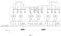
- the external power source may not be connected through the incoming power line, and power is taken by utilizing the medium voltage interconnecting line between the flexible direct-current traction substations from an external power source of the adjacent flexible direct-current traction substation, as illustrated in FIG. 3 .
- a power busbar SS 1 and a power busbar SS 2 of a traction substation j supply power through a medium voltage interconnecting line between the flexible direct-current traction substation j and a flexible direct-current traction substation j -1, and between the flexible direct-current traction substation j and a flexible direct-current traction substation j +1.
- a plurality of bidirectional converters in the flexible direct-current traction substation is in parallel operation, and traction power is balancedly distributed among sectionalized power busbars.
- a bidirectional converter to which the corresponding power busbar belongs is blocked or cut off, or power is taken from an overhead line to a station auxiliary load in a predetermined control mode, or it continues to operate and takes power through the medium voltage interconnecting line from an external power source of the adjacent flexible direct-current traction substation; an external power source and a bidirectional converter of the flexible direct-current traction substation in another branch are not affected; a traction load of the flexible direct-current traction system is powered by one or more bidirectional converters, that operates normally, in each of the plurality of flexible traction substations; and the station auxiliary load in the branch is powered from the overhead line by the bidirectional converter in the branch, or is powered by a power busbar of the flexible direct-current traction substation in the other branch through a switched-on busbar switch, or is powered by the medium voltage interconnecting line from the
- a traction load of the flexible direct-current traction system is powered by one or more bidirectional converters, that operates normally, in each of the plurality of flexible traction substations; and a station auxiliary load of the flexible direct-current traction substation is powered by a bidirectional converter from an overhead line, or is powered by a medium voltage interconnecting line from an external power source of the adjacent flexible direct-current traction substation.
- an operation mode of a flexible direct-current traction substation connected to the incoming power line is the same as that introduced above.
- the power busbar takes power from a non-faulty external power source or a non-faulty power busbar through switching a medium voltage interconnecting line or switching on a busbar switch.
- the power busbar takes power from the non-faulty external power source or the non-faulty power busbar through switching the interconnecting line or switching on the busbar switch; or the bidirectional converter continues to operate in a controlled state when the medium voltage interconnecting line is not switched, and power is taken by the bidirectional converter from the overhead line.
- each power busbar in both branches are respectively connected to power busbars of two adjacent flexible direct-current traction substations, and each power busbar may be powered by the incoming power lines in both branches.
- each power busbar is only connected to a power busbar of the adjacent flexible direct-current traction substation in one branch.
- each power busbar of the flexible direct-current traction substation not connected to the incoming power line is only powered by the incoming power line in one branch.
- the power busbar SS 1 of the traction substation j is powered by a medium voltage interconnecting line between the flexible direct-current traction substation j -1 and the flexible direct-current traction substation j
- the power busbar SS 2 of the traction substation j is powered by a medium voltage interconnecting line between the flexible direct-current traction substation j +1 and the flexible direct-current traction substation j .
- the remaining structure of FIG. 4 is the same as that of FIG. 3 .
- a power supply mode of the flexible direct-current traction substation connected to the incoming power line is the same as that illustrated in FIG. 1 and FIG. 2 ; and in the flexible direct-current traction substation not connected to the incoming power line, the power busbar takes power from the external power source of the adjacent substation through the medium voltage interconnecting line.
- the power supply mode of the flexible direct-current traction substation connected to the incoming power line is the same as the system illustrated in FIG. 1 and FIG. 2 ; for the flexible direct-current traction substation not connected to the incoming power line, the external power source and the bidirectional converter of the flexible direct-current traction substation in the other branch are not affected; the traction load of the flexible direct-current traction system is powered by the one or more bidirectional converters, that operates normally, in each of the plurality of flexible traction substations; and the station auxiliary load in the branch is powered from the overhead line by the bidirectional converter in the branch, or is powered by the power busbar of the flexible direct-current traction substation in the other branch through the switched-on busbar switch.
- the power supply mode of the flexible direct-current traction substation connected to the incoming power line is the same as the system illustrated in FIG. 1 and FIG. 2 ; for the flexible direct-current traction substation not connected to the incoming power line, the traction load of the flexible direct-current traction system is powered by the one or more bidirectional converters, that operates normally, in each of the plurality of flexible traction substations; and the station auxiliary load in the branch is powered from the overhead line by the bidirectional converter in the branch, or is powered by the power busbar of the flexible direct-current traction substation in the other branch through the switched-on busbar switch.
- the traction load of the flexible direct-current traction system is powered by the one or more bidirectional converters, that operates normally, in each of the plurality of flexible traction substations; and the station auxiliary load in the branch is powered from the overhead line by the bidirectional converter in the branch, or is powered by the power busbar of the flexible direct-current traction substation in the other branch through the switched-on busbar switch.
- the flexible direct-current traction power supply system illustrated in FIG. 1 includes a medium-voltage looped network.
- Each of the first power busbar SS 1 and the second power busbar SS 2 is connected to a power busbar in an adjacent flexible direct-current traction substation through a circuit breaker.
- FIG. 1 shows a schematic diagram of main wiring by taking external power sources i-1, i, and i +1 and traction substations j -1, j, and j +1 in a distributed power supply mode as an example.
- the jth traction substation T j two incoming power lines TL 1 and TL 2 are provided.
- a voltage level of each of the two incoming power lines TL 1 and TL 2 may be 220kV, 110kV, 35kV, or 10kV, but not limited to the foregoing several voltage levels.
- the incoming power line TL 1 and the incoming power line TL 2 are respectively connected to the power busbar SS 1 and the power busbar SS 2 through the circuit breaker BS 2 and the circuit breaker BS 5 .
- the power busbar SS 1 and the power busbar SS 2 are respectively connected to the external power source i -1 through the circuit breaker BS 1 and the circuit breaker BS 4 , and respectively connected to the external power source i +1 through the circuit breaker BS 3 and the circuit breaker BS 6 .
- the power busbar SS 1 and the power busbar SS 2 are respectively connected to the traction transformer TC 1 and the traction transformer TC 2 through circuit breakers BC 1 and BC 2 .
- the traction transformer TC 1 and the traction transformer TC 2 are respectively connected to the bidirectional converter C 1 and the bidirectional converter C 2 .
- the power busbars SS 1 is connected to the distribution transformer TD 1 through the circuit breaker BD 1 to power the station auxiliary load.
- the power busbar SS 2 is connected to the distribution transformer TD 2 through the circuit breaker BD 2 to power the station auxiliary load.
- Each of positive electrodes of the bidirectional converter C 1 and the bidirectional converter C 2 is respectively connected to the traction busbar ST through the circuit breaker BM 1 and the circuit breaker BM 2 , and negative electrodes of the bidirectional converter C 1 and the bidirectional converter C 2 are grounded.
- a voltage level of the traction busbar ST may be 3kV, 1.5kV, or 750V, but is not limited to the foregoing several voltage levels.
- the traction busbar ST is connected to the overhead line through the circuit breaker, and the overhead line may include an up-track overhead line and a down-track overhead line.
- the medium-voltage looped network is composed of the power busbar of the flexible direct-current traction substation and a circuit breaker between power busbars of different flexible direct-current traction substations.
- the medium-voltage looped network only needs to power the station auxiliary load of the flexible direct-current traction substation rather than power the traction load.
- FIG. 1 in the normal operation mode, the rest of circuit breakers are turned on except that a sectionalized circuit breaker BF 1 of the power busbar and a circuit breaker between the power busbars of the traction substations are turned off.
- the circuit breaker BS 3 and the circuit breaker BS 4 between the power busbars of the flexible direct-current traction substations are switched on; the circuit breaker BS 1 and the circuit breaker BS 6 between the power busbars of the flexible direct-current traction substations, or the circuit breaker BS 1 and the circuit breaker BS 4 between the power busbars of the flexible direct-current traction substations are switched on, or the circuit breaker BS 3 and the circuit breaker BS 6 between the power busbars of the flexible direct-current traction substations are switched on.
- the adjacent flexible direct-current traction substation supplies power, and the bidirectional converter on the power busbar corresponding to the faulty incoming line is blocked or cut off, or power is taken from the overhead line to the station auxiliary load in the predetermined control mode, or it continues to operate, and the power is taken through the medium voltage interconnecting line from the external power source of the adjacent flexible direct-current traction substation.
- the bidirectional converter In a case where the bidirectional converter fails, the bidirectional converter quits operation, and a switch between the faulty bidirectional converter and the traction busbar and a switch between the faulty bidirectional converter and the power busbar are switched off.
- predetermined system-level wide-area coordination control should be used to regulate a voltage or power of each flexible direct-current traction substation, resulting in a smaller voltage deviation of the whole line, more balanced power output of the flexible direct-current traction substation, a higher energy utilization rate, and the ability for mutual support among various flexible direct-current traction substations under a fault condition.
- Each flexible direct-current traction substation is connected to converters of two different sections of power busbars and employs dynamic current-sharing control.
- the medium-voltage looped network may also be canceled, and a circuit breaker and a medium voltage interconnecting line between the flexible direct-current traction substations may be omitted.
- FIG. 2 shows a schematic diagram of the main wiring by taking external power sources i -1, i, and i +1 and traction substations j -1, j, and j +1 in the distributed power supply mode as an example.
- the two incoming power lines TL 1 and TL 2 are provided.
- the voltage level thereof may be 220kV, 110kV, 35kV, or 10kV, but not limited to the foregoing several voltage levels.
- the incoming power line TL 1 and the incoming power line TL 2 are respectively connected to the power busbar SS 1 and the power busbar SS 2 through the circuit breaker BS 2 and the circuit breaker BS 5 .
- the power busbar SS 1 and the power busbar SS 2 are respectively connected to the traction transformer TC 1 and the traction transformer TC 2 through circuit breakers BC 1 and BC 2 .
- the traction transformer TC 1 and the traction transformer TC 2 are respectively connected to the bidirectional converter C 1 and the bidirectional converter C 2 .
- the power busbars SS 1 is connected to the distribution transformer TD 1 through the circuit breaker BD 1 to power the station auxiliary load.
- the power busbar SS 2 is connected to the distribution transformer TD 2 through the circuit breaker BD 2 to power the station auxiliary load.
- Each of the positive electrodes of the bidirectional converter C 1 and the bidirectional converter C 2 is respectively connected to the traction busbar ST through the circuit breaker BM 1 and the circuit breaker BM 2 , and the negative electrodes of the bidirectional converter C 1 and the bidirectional converter C 2 are grounded.
- the voltage level of the traction busbar ST may be 3kV, 1.5kV, or 750V, but is not limited to the foregoing several voltage levels.
- the traction busbar ST is connected to the overhead line through the circuit breaker, and the overhead line may include the up-track overhead line and the down-track overhead line.
- a control and protection system of the bidirectional converter may take power from the external power source and the overhead line, and a dual power take circuit of the bidirectional converter is illustrated in FIG. 5 .
- the control and protection system of the bidirectional converter may take power from the power busbar SS or the traction busbar ST.
- part of the plurality of flexible direct-current traction substations may not be connected to the external power source through the incoming power line.
- part of the plurality of flexible direct-current traction substations omits the external power source and incoming lines of the external power sources in two branches.
- the flexible direct-current traction substation j -1 and the flexible direct-current traction substation j +1 are flexible direct-current traction substations connected to the incoming power line
- the flexible direct-current traction substation j is the flexible direct-current traction substation not connected to the incoming power line.
- the flexible direct-current traction substation j has the same remaining structure as that of FIG. 1 and FIG. 2 except for lacking the external power source and the incoming power lines in two branches.
- a part of the plurality of flexible direct-current traction substations is connected to the external power source through the incoming power line, another part of the plurality of flexible direct-current traction substations is connected to the external power source without the incoming power line.
- an operation mode of the flexible direct-current traction substation connected to the incoming power line is the same as that of the flexible direct-current traction power supply system illustrated in FIG. 1 and FIG. 2 ; and for the flexible direct-current traction substation not connected to the incoming power line, the power busbar takes power from the external power source of the adjacent flexible direct-current traction substation through the medium voltage interconnecting line.
- the flexible direct-current traction substation connected to the incoming power line has the same operation mode as the flexible direct-current traction power supply system illustrated in FIG. 1 and FIG. 2 .
- the power busbar takes power from an external power source of a non-faulty adjacent flexible direct-current traction substation through the medium voltage interconnecting line by switching an interconnecting line.
- the flexible direct-current traction substation connected to the incoming power line has the same operation mode as the flexible direct-current traction power supply system illustrated in FIG. 1 and FIG. 2 .
- the power busbar takes power from the non-faulty external power source or the non-faulty power busbar through switching the medium voltage interconnecting line or switching on the busbar switch.
- the power busbar takes power from the non-faulty external power source or the non-faulty power busbar through switching the interconnecting line or switching on the busbar switch; or the medium voltage interconnecting line is not switched, the bidirectional converter continues to operate in the controlled state, and the power is taken by the bidirectional converter from the overhead line to the station auxiliary load.
- each flexible direct-current traction substation at least includes two independent power busbars leading from different external incoming power lines, and a sectionalized circuit breaker of the two power busbars are in a disconnected state under a normal condition; a power busbar in each branch is connected to at least a group of a bidirectional converter and a corresponding traction transformer; the medium voltage interconnecting line and the tie switch are provided between the power busbars of the adjacent flexible direct-current traction substation; when an incoming line of the external power source of the flexible direct-current traction substation in a branch fails, a bidirectional converter in the branch is blocked or cut off, or the power is taken from the overhead line to the station auxiliary load in the predetermined control mode, or it continues to operate and power is taken by the medium voltage interconnecting line from the external power source of the adjacent flexible direct-current traction substation,
- each flexible direct-current traction substation at least includes two independent power busbars leading from different external incoming power lines, and a sectionalized circuit breaker of the power busbars in both branches is in the disconnected state under the normal condition; the power busbar in each branch is connected to the at least one group of the bidirectional converter and the corresponding traction transformer; when an incoming line of the external power source of the flexible direct-current traction substation in a branch fails, a bidirectional converter in the branch is blocked or cut off, or the power is taken from the overhead line to the station auxiliary load in a special control mode, while the rest of bidirectional converters maintains operation; and when incoming lines of the external power source of the flexible direct-current traction substation in at least two branches fail, the corresponding bidirectional converter takes power from the overhead line to the station auxiliary load in the special control mode, while the rest of bidirectional converters maintains operation.
- an illustrated transformer takes a dual-winding transformer an example, and may be a transformer in different forms such as a three-winding transformer, which is not limited herein.
- a main wiring form of the distributed power supply mode is used for description.
- an actual line adopts a centralized power supply mode or a hybrid power supply mode i.e., part of the plurality of flexible direct-current traction substations uses the centralized power supply mode and another part of the plurality of flexible direct-current traction substations uses the distributed power supply mode, and the method is also applicable and is not limited herein.
- the overhead line may be a single-row line or a dual-row line.
- a traction line is connected to an overhead line of the dual-row line through circuit breaker lines in both branches.
- rail transit includes an up-track line and a down-track line.
- a busbar switch is provided between the first power busbar and the second power busbar, wiring is performed through single busbar sectionalization, and the busbar switch is switched off during normal operation; or the first power busbar and the second power busbar are an independent dual-power busbar.
- the power busbar in each flexible direct-current traction substation is in the form of main wiring of single busbar sectionalization, and one circuit breaker is provided between power busbars in each flexible direct-current traction substation.
- other wiring forms such as a double busbar may be used. The embodiments of the present disclosure do not limit this herein.
- the at least one group of the bidirectional converter and the traction transformer are connected between the power busbar and the traction busbar, and the number of the bidirectional converters and the number of the traction transformers is one-to-one.
- FIG. 1 , FIG. 2 , FIG. 3 , and FIG. 4 only two transformers are connected to each section of the power busbar to power the station auxiliary load.
- a plurality of transformers may be employed to power the station auxiliary load during actual operation.
- the flexible direct-current traction power supply system connected to the distributed external power source fully utilizes the technical characteristics of the bidirectional converter. Moreover, by efficiently harnessing both the external power source of a rail transit traction system and device capacity inside the traction substation, the system remarkably improves power supply capacity and a power supply range of the direct-current traction power supply system, reduces an engineering cost of the direct-current traction power supply system, and is suitable for use of a flexible direct-current traction power supply system in newly-built urban or intercity rail transit lines or is suitable for local or full-line technical transformation of an existing direct-current traction power supply system with insufficient power supply capacity.
- This solution provides main wiring and an operation mode of a flexible direct-current traction power supply mode, which modifies a system structure on the premise of ensuring safety and reliability, and provides a technical solution for actual engineering of applying the flexible direct-current power supply technology in the future.
- FIG. 6 is a flowchart of a method for operating a flexible direct-current traction power supply system connected to a distributed external power source according to an embodiment of the present disclosure.
- the method for operating the flexible direct-current traction power supply system connected to the distributed external power source includes steps S101 to S104.
- step S101 during normal operation, a plurality of bidirectional converters in the substation is in parallel operation, and traction power is balancedly distributed between sectionalized power busbars.
- step S102 when an external power source or an incoming power line of the flexible direct-current traction substation connected to an incoming power line fails, based on different fault types, a bidirectional converter to which the corresponding power busbar belongs is blocked or cut off, or power is taken from an overhead line to a station auxiliary load in a predetermined control mode, or it continues to operate and power is taken through the medium voltage interconnecting line from an external power source of the adjacent flexible direct-current traction substation. An external power source and a bidirectional converter of the flexible direct-current traction substation in another branch are not affected.
- a traction load of the flexible direct-current traction system is powered by one or more bidirectional converters, that operates normally, in each of the plurality of flexible traction substations.
- the station auxiliary load in the branch is powered from the overhead line by the bidirectional converter in the branch, or by a power busbar of the flexible direct-current traction substation in the other branch through a switched-on busbar switch, or by the medium voltage interconnecting line from the external power source of the adjacent flexible direct-current traction substation.
- a traction load of the flexible direct-current traction system is powered by one or more bidirectional converters, that operates normally, in each of the plurality of flexible traction substations; and a station auxiliary load of the flexible direct-current traction substation is powered by the bidirectional converter from an overhead line, or by the medium voltage interconnecting line from an external power source of the adjacent flexible direct-current traction substation.
- step S104 when a branch to which a power busbar of a flexible direct-current traction not connected to an incoming power line belongs fails, or both branches to which power busbars belong fail, or a medium voltage interconnecting line in a branch fails, the power busbar takes power from a non-faulty external power source or a non-faulty power busbar through switching a medium voltage interconnecting line or switching on a busbar switch.
- the method for operating the flexible direct-current traction power supply system connected to the distributed external power source fully utilizes the technical characteristics of the bidirectional converter. Moreover, by efficiently harnessing both the external power source of the rail transit traction system and the device capacity inside the traction substation, the system remarkably improves the power supply capacity and the power supply range of the direct-current traction power supply system, reduces the engineering cost of the direct-current traction power supply system, and is suitable for the use of the flexible direct-current traction power supply system in newly-built urban or intercity rail transit lines or is suitable for the local or full-line technical transformation of the existing direct-current traction power supply system with insufficient power supply capacity.
- This solution provides the main wiring and the operation mode of the flexible direct-current traction power supply mode, which modifies the system structure on the premise of ensuring safety and reliability, and provides the technical solution for the actual engineering of applying the flexible direct-current power supply technology in the future.
- first or second is only for descriptive purposes, rather than indicating or implying relative importance or implicitly indicating the number of indicated technical features. Therefore, the features associated with “first” or “second” can explicitly or implicitly include at least one of the features. In the description of the present disclosure, “plurality of” means at least two, unless otherwise specifically indicated.
Landscapes
- Engineering & Computer Science (AREA)
- Power Engineering (AREA)
- Mechanical Engineering (AREA)
- Direct Current Feeding And Distribution (AREA)
- Electric Propulsion And Braking For Vehicles (AREA)
Abstract
Description
- The present application claims priority to
Chinese Patent Application No. 202110773536.7, entitled "FLEXIBLE DIRECT-CURRENT TRACTION POWER SUPPLY SYSTEM CONNECTED TO DISTRIBUTED EXTERNAL POWER SOURCE AND OPERATION METHOD THEREOF", filed with China National Intellectual Property Administration on July 08, 2021 by TSINGHUA UNIVERSITY - The present disclosure relates to the field of flexible direct-current traction power supply technologies, and more particularly, to a flexible direct-current traction power supply system connected to a distributed external power source and an operation method thereof.
- The flexible direct-current traction power supply technology may overcome the defects of a diode rectification power supply scheme and an energy-feedback-type power supply scheme to a great extent, making it a future development trend. With the rapid growth in urban rail transit capacity and mileage, the requirements for power supply capacity and distance of a direct-current traction power supply system increase accordingly. In order to solve the issues of high requirements for external power sources, a low utilization rate of redundancy capacity of a traction substation, too large energy consumption, or the like in a traditional direct-current traction power supply system, it is necessary to study a flexible direct-current traction power supply scheme.
- Currently, research results related to the flexible direct-current traction power supply scheme mainly focus on a system structure, a power electronic topology structure, and relevant control aspects. However, practical application of the flexible direct-current traction power supply scheme inevitably involves design and selection of main wiring and an operation mode of the flexible direct-current traction power supply system. Therefore, it is essential to study the main wiring and operation mode of the flexible direct-current traction power supply system.
- The present disclosure aims to solve at least one of the technical problems in the related art to some extent.
- To this end, an object of the present disclosure is to provide a flexible direct-current traction power supply system connected to a distributed external power source, which is capable of lowering the demand for an external power source in the flexible direct-current traction power supply system and enhancing a capacity utilization rate of a traction substation device and a utilization rate of locomotive regenerative braking energy, allowing to conserve energy and carbon and control power quality of an alternating-current and direct-current system, thereby bringing numerous advantages to the traction power supply system. In addition, a technical scheme may be provided for practical engineering of flexible direct-current traction power supply technology in rail transit.
- Another object of the present disclosure is to provide a method for operating a flexible direct-current traction power supply system connected to a distributed external power source.
- In order to achieve the above objects, an embodiment in an aspect of the present disclosure provides a flexible direct-current traction power supply system connected to a distributed external power source, including: a plurality of flexible direct-current traction substations. Each of the plurality of flexible direct-current traction substations includes: a first incoming power line and a second incoming power line that are connected to an external power source; a first power busbar connected to the first incoming power line through a circuit breaker, and a second power busbar connected to the second incoming power line through a circuit breaker; a first traction transformer having one end connected to the first power busbar through a circuit breaker and another end connected to an alternating current side of a first bidirectional converter, the first bidirectional converter having a direct current side connected to a traction busbar through a circuit breaker, and the traction busbar being connected to an overhead line through a circuit breaker; a second traction transformer having one end connected to the second power busbar through a circuit breaker and another end connected to an alternating current side of a second bidirectional converter, the second bidirectional converter having a direct current side connected to the traction busbar through a circuit breaker, and the traction busbar being connected to the overhead line through a circuit breaker; a first distribution transformer connected to the first power busbar through a circuit breaker and a second distribution transformer connected to the second power busbar through a circuit breaker. Each of the first power busbar and the second power busbar of the flexible direct-current traction substation is connected to a power busbar in an adjacent flexible direct-current traction substation through a circuit breaker and a medium voltage interconnecting line.
- In addition, the flexible direct-current traction power supply system connected to the distributed external power source according to the above embodiments of the present disclosure may further have the following additional technical features.
- In an embodiment of the present disclosure, the flexible direct-current traction power supply system connected to the distributed external power source further includes: removing the circuit breaker and the medium voltage interconnecting line between power busbars of two flexible direct-current traction substations.
- In an embodiment of the present disclosure, the flexible direct-current traction power supply system connected to the distributed external power source further includes: removing a circuit breaker and an incoming power line between a power busbar and an external power source of part of the plurality of flexible direct-current traction substations, such that the external power source of the part of the plurality of flexible direct-current traction substations is removed, and the flexible direct-current traction substation not connected to an incoming power line is powered by an external power source of an adjacent flexible direct-current traction substation and a medium voltage interconnecting line between flexible direct-current traction substations during normal operation.
- In an embodiment of the present disclosure, a busbar switch is provided between the first power busbar and the second power busbar, wiring is performed through single busbar sectionalization, and the busbar switch is switched off during normal operation; or the first power busbar and the second power busbar are an independent dual-power busbar.
- In an embodiment of the present disclosure, the flexible direct-current traction power supply system connected to the distributed external power source further includes: at least a group of a bidirectional converter and a traction transformer provided between the power busbar and the traction busbar.
- In an embodiment of the present disclosure, during normal operation of the flexible direct-current traction substation, a plurality of bidirectional converters in the flexible direct-current traction substation is in parallel operation, and traction power is balancedly distributed among sectionalized power busbars.
- In an embodiment of the present disclosure, when an external power source or an incoming power line of the flexible direct-current traction substation in a branch fails, based on different fault types, a bidirectional converter to which the corresponding power busbar belongs is blocked or cut off, or power is taken from an overhead line to a station auxiliary load in a predetermined control mode, or it continues to operate and takes power through the medium voltage interconnecting line from an external power source of the adjacent flexible direct-current traction substation; an external power source and a bidirectional converter of the flexible direct-current traction substation in another branch are not affected; a traction load of the flexible direct-current traction system is powered by one or more bidirectional converters, that operates normally, in each of the plurality of flexible traction substations; and the station auxiliary load in the branch is powered from the overhead line by the bidirectional converter in the branch, or is powered by a power busbar of the flexible direct-current traction substation in the other branch through a switched-on busbar switch, or is powered by the medium voltage interconnecting line from the external power source of the adjacent flexible direct-current traction substation.
- In an embodiment of the present disclosure, when external power source or incoming power lines of the flexible direct-current traction substation in both branches fail, a traction load of the flexible direct-current traction system is powered by one or more bidirectional converters, that operates normally, in each of the plurality of flexible traction substations; and a station auxiliary load of the flexible direct-current traction substation is powered by a bidirectional converter from an overhead line, or is powered by a medium voltage interconnecting line from an external power source of the adjacent flexible direct-current traction substation.
- In an embodiment of the present disclosure, when a branch to which a power busbar of a flexible direct-current traction substation not connected to an incoming power line belongs fails, or both branches to which power busbars belong fail, or a medium voltage interconnecting line fails, the power busbar takes power from a non-faulty external power source or a non-faulty power busbar through switching a medium voltage interconnecting line or switching on a busbar switch.
- In order to achieve the above objects, an embodiment in an aspect of the present disclosure provides a method for operating a flexible direct-current traction power supply system connected to a distributed external power source. For any flexible direct-current traction substation, the method includes: during normal operation, a plurality of bidirectional converters being in parallel operation, and traction power being balancedly distributed between sectionalized power busbars; when an external power source or an incoming power line of the flexible direct-current traction substation connected to an incoming power line fails, based on different fault types, blocking or cutting off a bidirectional converter to which the corresponding power busbar belongs, or taking power from an overhead line to a station auxiliary load in a predetermined control mode, or continuing to operate and taking power through the medium voltage interconnecting line from an external power source of the adjacent flexible direct-current traction substation; wherein an external power source and a bidirectional converter of the flexible direct-current traction substation in another branch are not affected; powering a traction load of the flexible direct-current traction system by one or more bidirectional converters, that operates normally, in each of the plurality of flexible traction substations; and powering the station auxiliary load in the branch from the overhead line by the bidirectional converter in the branch, or by a power busbar of the flexible direct-current traction substation in the other branch through a switched-on busbar switch, or by the medium voltage interconnecting line from the external power source of the adjacent flexible direct-current traction substation; when both external power sources or both incoming power lines of the flexible direct-current traction substation connected to the incoming power lines fail, powering a traction load of the flexible direct-current traction system by one or more bidirectional converters, that operates normally, in each of the plurality of flexible traction substations; and powering a station auxiliary load of the flexible direct-current traction substation by the bidirectional converter from an overhead line, or by the medium voltage interconnecting line from an external power source of the adjacent flexible direct-current traction substation; and when a branch to which a power busbar of a flexible direct-current traction not connected to an incoming power line belongs fails, or both branches to which power busbars belong fail, or a medium voltage interconnecting line in a branch fails, the power busbar taking power from a non-faulty external power source or a non-faulty power busbar through switching a medium voltage interconnecting line or switching on a busbar switch.
- The flexible direct-current traction power supply system connected to the distributed external power source and the operation method thereof according to the embodiments of the present disclosure have the following advantages.
- 1) They possess the advantage of optimizing configuration of the external power source. They are compatible with various voltage levels of external power sources, such as 10/35kV, which may reduce a number of external power sources by approximately 25% and decrease capacity of external power sources by about 50%. Through system-level wide-area coordination control between traction substations, peak power of a single traction substation is lowered. In a normal operation mode, multiple section busbars within the traction substation power both the traction load and the station auxiliary load, resulting in more balanced power of incoming lines in both branches, thereby significantly lowering standby capacity of the incoming lines. In a fault operation mode, the converter may quit the operation or adopt a special control mode to provide mutual support through the system-level wide-area coordination control, allowing for a remarkable reduction in standby capacity of a medium-voltage looped network.
- 2) They possess the advantage of improved transport capacity. By utilizing decoupling characteristics of a power electronic converter, an electrical connection between a public power grid and the overhead line is transformed into an energy connection, thereby eliminating the influence of voltage drops of a public power grid, the traction transformer, and a rectifier unit on a voltage of the overhead line. Through flexible voltage control technology, an improvement in voltage stability of the overhead line is realized under normal and fault working conditions, allowing for an increase in train density on the basis that the voltage of the overhead line is ensured to remain within a reasonable operation range.
- 3) They possess the advantage of an improved utilization rate of regenerative energy. The system-level wide-area coordination control between the traction substations actively regulates system load flow, which increases a utilization rate of locomotive regenerative energy to about 90%.
- Additional aspects and advantages of the present disclosure will be provided in part in the following description, or will become apparent in part from the following description or can be learned from practice of the present disclosure.
- The above and/or additional aspects and advantages of the present disclosure will become apparent and readily appreciated from the following description of the embodiments in conjunction with the accompanying drawings.
-
FIG. 1 is a schematic structural diagram of a flexible direct-current traction power supply system connected to a distributed external power source according to an embodiment of the present disclosure. -
FIG. 2 is a schematic structural diagram of a flexible direct-current traction power supply system connected to a distributed external power source according to another embodiment of the present disclosure. -
FIG. 3 is a schematic structural diagram of a flexible direct-current traction power supply system connected to a distributed external power source according to yet another embodiment of the present disclosure. -
FIG. 4 is a schematic structural diagram of a flexible direct-current traction power supply system connected to a distributed external power source according to still yet another embodiment of the present disclosure. -
FIG. 5 is a schematic diagram of a dual power take circuit of a control and protection system of a converter according to an embodiment of the present disclosure. -
FIG. 6 is a flowchart of a method for operating a flexible direct-current traction power supply system connected to a distributed external power source according to an embodiment of the present disclosure. - Embodiments of the present disclosure will be described in detail below with reference to examples thereof as illustrated in the accompanying drawings, throughout which same or similar elements, or elements having same or similar functions, are denoted by same or similar reference numerals. The embodiments described below with reference to the drawings are illustrative only, and are intended to explain, rather than limiting, the present disclosure.
- A flexible direct-current traction power supply system connected to a distributed external power source and an operation method thereof according to the embodiments of the present disclosure are described with reference to the accompanying drawings.
- A flexible direct-current traction power supply system connected to a distributed external power source according to an embodiment of the present disclosure is described first with reference to the accompanying drawings.
-
FIG. 1 is a schematic structural diagram of a flexible direct-current traction power supply system connected to a distributed external power source according to an embodiment of the present disclosure. - As illustrated in
FIG. 1 , the flexible direct-current traction power supply system connected to the distributed external power source includes a plurality of flexible direct-current traction substations. - Optionally, each of the plurality of flexible direct-current traction substations includes an external power source and a traction substation. Each flexible direct-current traction substation includes the following content. A first incoming power line TL1 and a second incoming power line TL2 are connected to an external power source. A first power busbar SS1 is connected to the first incoming power line TL1 through a circuit breaker BS2, and a second power busbar SS2 is connected to the second incoming power line TL2 through a circuit breaker BS5.
- A first traction transformer TC1 has one end connected to the first power busbar SS1 through a circuit breaker BC1 and another end connected to an alternating current side of a first bidirectional converter C1. The first bidirectional converter C1 is connected to a traction busbar ST through a circuit breaker. As a specific connection mode, a positive electrode of the first bidirectional converter C1 on a direct current side is connected to a positive electrode of the traction busbar ST through a circuit breaker BM1 and a negative electrode of the first bidirectional converter C1 on a direct current side is connected to a negative electrode of the traction busbar ST. Moreover, the positive electrode of the traction busbar ST is connected to an overhead line through a circuit breaker. In an example of the present disclosure, the negative electrode of the traction busbar ST is grounded.
- A second traction transformer TC2 has one end connected to the second power busbar SS2 through a circuit breaker BC2 and another end connected to an alternating current side of a second bidirectional converter C2. The second bidirectional converter C2 is connected to the traction busbar ST through a circuit breaker. As a specific connection mode, a positive electrode of the second bidirectional converter C2 on a direct current side is connected to the positive electrode of the traction busbar ST through a circuit breaker BM2 and a negative electrode of the second bidirectional converter C2 on a direct current side is connected to the negative electrode of the traction busbar. Moreover, the positive electrode of the traction busbar ST is connected to the overhead line through a circuit breaker. In an example of the present disclosure, the negative electrode of the traction busbar ST is grounded.
- A first distribution transformer TD1 is connected to the first power busbar SS1 through a circuit breaker BD1, and a second distribution transformer TD2 is connected to the second power busbar SS2 through a circuit breaker BD2.
- Each of the first power busbar SS1 and the second power busbar SS1 of the flexible direct-current traction substation is connected to a power busbar in an adjacent flexible direct-current traction substation through a circuit breaker and a medium voltage interconnecting line.
- In some embodiments, the flexible direct-current traction power supply system connected to the distributed external power source further includes: removing the circuit breaker and the medium voltage interconnecting line between power busbars of two flexible direct-current traction substations.
- It can be understood that, as illustrated in
FIG. 2 , no medium voltage interconnecting line may be provided between two flexible direct-current traction substations. - In some embodiments, the flexible direct-current traction power supply system connected to the distributed external power source further includes: removing a circuit breaker and an incoming power line between a power busbar and an external power source of part of the plurality of flexible direct-current traction substations, such that the external power source of the part of the plurality of flexible direct-current traction substations is removed, and the flexible direct-current traction substation not connected to an incoming power line is powered by an external power source of an adjacent flexible direct-current traction substation and a medium voltage interconnecting line between flexible direct-current traction substations during normal operation.
- It can be understood that, in a certain flexible direct-current traction substation, the external power source may not be connected through the incoming power line, and power is taken by utilizing the medium voltage interconnecting line between the flexible direct-current traction substations from an external power source of the adjacent flexible direct-current traction substation, as illustrated in
FIG. 3 . A power busbar SS1 and a power busbar SS2 of a traction substation j supply power through a medium voltage interconnecting line between the flexible direct-current traction substation j and a flexible direct-current traction substation j-1, and between the flexible direct-current traction substation j and a flexible direct-current tractionsubstation j+ 1. - In some embodiments, during normal operation of the flexible direct-current traction substation, a plurality of bidirectional converters in the flexible direct-current traction substation is in parallel operation, and traction power is balancedly distributed among sectionalized power busbars.
- In some embodiments, when an external power source or an incoming power line of the flexible direct-current traction substation in a branch fails, based on different fault types, a bidirectional converter to which the corresponding power busbar belongs is blocked or cut off, or power is taken from an overhead line to a station auxiliary load in a predetermined control mode, or it continues to operate and takes power through the medium voltage interconnecting line from an external power source of the adjacent flexible direct-current traction substation; an external power source and a bidirectional converter of the flexible direct-current traction substation in another branch are not affected; a traction load of the flexible direct-current traction system is powered by one or more bidirectional converters, that operates normally, in each of the plurality of flexible traction substations; and the station auxiliary load in the branch is powered from the overhead line by the bidirectional converter in the branch, or is powered by a power busbar of the flexible direct-current traction substation in the other branch through a switched-on busbar switch, or is powered by the medium voltage interconnecting line from the external power source of the adjacent flexible direct-current traction substation.
- In some embodiments, when external power source or incoming power lines of the flexible direct-current traction substation in both branches fail, a traction load of the flexible direct-current traction system is powered by one or more bidirectional converters, that operates normally, in each of the plurality of flexible traction substations; and a station auxiliary load of the flexible direct-current traction substation is powered by a bidirectional converter from an overhead line, or is powered by a medium voltage interconnecting line from an external power source of the adjacent flexible direct-current traction substation.
- In some embodiments, in the flexible direct-current traction power supply system including the flexible direct-current traction substation not connected to the incoming power line, an operation mode of a flexible direct-current traction substation connected to the incoming power line is the same as that introduced above. In the flexible direct-current traction substation not connected to the incoming power line, when an external power source or an incoming power line in a branch fails, or external power source or the incoming power lines in both branches fail, the power busbar takes power from a non-faulty external power source or a non-faulty power busbar through switching a medium voltage interconnecting line or switching on a busbar switch.
- When a medium voltage interconnecting line in the flexible direct-current traction substation not connected to the incoming power line fails, the power busbar takes power from the non-faulty external power source or the non-faulty power busbar through switching the interconnecting line or switching on the busbar switch; or the bidirectional converter continues to operate in a controlled state when the medium voltage interconnecting line is not switched, and power is taken by the bidirectional converter from the overhead line.
- In
FIG. 3 , in one flexible direct-current traction substation not connected to the incoming power line, power busbars in both branches are respectively connected to power busbars of two adjacent flexible direct-current traction substations, and each power busbar may be powered by the incoming power lines in both branches. As another connection mode of the flexible direct-current traction substation not connected to the incoming power line, as illustrated inFIG. 4 , each power busbar is only connected to a power busbar of the adjacent flexible direct-current traction substation in one branch. - In
FIG. 4 , each power busbar of the flexible direct-current traction substation not connected to the incoming power line is only powered by the incoming power line in one branch. For example, the power busbar SS1 of the traction substation j is powered by a medium voltage interconnecting line between the flexible direct-current traction substation j-1 and the flexible direct-current traction substation j, and the power busbar SS2 of the traction substation j is powered by a medium voltage interconnecting line between the flexible direct-current traction substation j+1 and the flexible direct-current traction substation j. In addition, the remaining structure ofFIG. 4 is the same as that ofFIG. 3 . - In a system illustrated in
FIG. 4 , during normal operation, a power supply mode of the flexible direct-current traction substation connected to the incoming power line is the same as that illustrated inFIG. 1 andFIG. 2 ; and in the flexible direct-current traction substation not connected to the incoming power line, the power busbar takes power from the external power source of the adjacent substation through the medium voltage interconnecting line. - In the system illustrated in
FIG. 4 , when the external power source or the incoming power line in one branch fails, the power supply mode of the flexible direct-current traction substation connected to the incoming power line is the same as the system illustrated inFIG. 1 andFIG. 2 ; for the flexible direct-current traction substation not connected to the incoming power line, the external power source and the bidirectional converter of the flexible direct-current traction substation in the other branch are not affected; the traction load of the flexible direct-current traction system is powered by the one or more bidirectional converters, that operates normally, in each of the plurality of flexible traction substations; and the station auxiliary load in the branch is powered from the overhead line by the bidirectional converter in the branch, or is powered by the power busbar of the flexible direct-current traction substation in the other branch through the switched-on busbar switch. - When the external power source or the incoming power lines in both branches fail, the power supply mode of the flexible direct-current traction substation connected to the incoming power line is the same as the system illustrated in
FIG. 1 andFIG. 2 ; for the flexible direct-current traction substation not connected to the incoming power line, the traction load of the flexible direct-current traction system is powered by the one or more bidirectional converters, that operates normally, in each of the plurality of flexible traction substations; and the station auxiliary load in the branch is powered from the overhead line by the bidirectional converter in the branch, or is powered by the power busbar of the flexible direct-current traction substation in the other branch through the switched-on busbar switch. - For the flexible direct-current traction substation not connected to the incoming power line, when a medium voltage interconnecting line in one of branches fails, an external power source or a bidirectional converter in another branch are not affected; the traction load of the flexible direct-current traction system is powered by the one or more bidirectional converters, that operates normally, in each of the plurality of flexible traction substations; and the station auxiliary load in the branch is powered from the overhead line by the bidirectional converter in the branch, or is powered by the power busbar of the flexible direct-current traction substation in the other branch through the switched-on busbar switch.
- The flexible direct-current traction power supply system connected to the distributed external power source according to an embodiment of the present disclosure will be described in detail below.
- The flexible direct-current traction power supply system illustrated in
FIG. 1 includes a medium-voltage looped network. Each of the first power busbar SS1 and the second power busbar SS2 is connected to a power busbar in an adjacent flexible direct-current traction substation through a circuit breaker. - Specifically, in conjunction with the flexible direct-current traction power supply system illustrated in
FIG. 1 , provided are m external power sources and n traction substations.FIG. 1 shows a schematic diagram of main wiring by taking external power sources i-1, i, and i+1 and traction substations j-1, j, and j+1 in a distributed power supply mode as an example. For the jth traction substation T j , two incoming power lines TL1 and TL2 are provided. Moreover, a voltage level of each of the two incoming power lines TL1 and TL2 may be 220kV, 110kV, 35kV, or 10kV, but not limited to the foregoing several voltage levels. The incoming power line TL1 and the incoming power line TL2 are respectively connected to the power busbar SS1 and the power busbar SS2 through the circuit breaker BS2 and the circuit breaker BS5. The power busbar SS1 and the power busbar SS2 are respectively connected to the external power source i-1 through the circuit breaker BS1 and the circuit breaker BS4, and respectively connected to the external power source i+1 through the circuit breaker BS3 and the circuit breaker BS6. The power busbar SS1 and the power busbar SS2 are respectively connected to the traction transformer TC1 and the traction transformer TC2 through circuit breakers BC1 and BC2. The traction transformer TC1 and the traction transformer TC2 are respectively connected to the bidirectional converter C1 and the bidirectional converter C2. The power busbars SS1 is connected to the distribution transformer TD1 through the circuit breaker BD1 to power the station auxiliary load. The power busbar SS2 is connected to the distribution transformer TD2 through the circuit breaker BD2 to power the station auxiliary load. Each of positive electrodes of the bidirectional converter C1 and the bidirectional converter C2 is respectively connected to the traction busbar ST through the circuit breaker BM1 and the circuit breaker BM2, and negative electrodes of the bidirectional converter C1 and the bidirectional converter C2 are grounded. A voltage level of the traction busbar ST may be 3kV, 1.5kV, or 750V, but is not limited to the foregoing several voltage levels. Moreover, the traction busbar ST is connected to the overhead line through the circuit breaker, and the overhead line may include an up-track overhead line and a down-track overhead line. - The medium-voltage looped network is composed of the power busbar of the flexible direct-current traction substation and a circuit breaker between power busbars of different flexible direct-current traction substations. The medium-voltage looped network only needs to power the station auxiliary load of the flexible direct-current traction substation rather than power the traction load.
- In
FIG. 1 , in the normal operation mode, the rest of circuit breakers are turned on except that a sectionalized circuit breaker BF1 of the power busbar and a circuit breaker between the power busbars of the traction substations are turned off. - In a case where the external power source or the incoming power line of the flexible direct-current traction substation in a branch fails, a faulty incoming line is cut off, a bidirectional converter on the power busbar corresponding to the faulty incoming line is blocked or cut off, or power is taken from the overhead line to the station auxiliary load in the predetermined control mode, or it continues to operate, and the power is taken through the medium voltage interconnecting line from the external power source of the adjacent flexible direct-current traction substation.
- In a case where the external power source or the incoming power lines of the flexible direct-current traction substation in both branches fail, the faulty incoming line is cut off, the circuit breaker BS3 and the circuit breaker BS4 between the power busbars of the flexible direct-current traction substations are switched on; the circuit breaker BS1 and the circuit breaker BS6 between the power busbars of the flexible direct-current traction substations, or the circuit breaker BS1 and the circuit breaker BS4 between the power busbars of the flexible direct-current traction substations are switched on, or the circuit breaker BS3 and the circuit breaker BS6 between the power busbars of the flexible direct-current traction substations are switched on. Moreover, the adjacent flexible direct-current traction substation supplies power, and the bidirectional converter on the power busbar corresponding to the faulty incoming line is blocked or cut off, or power is taken from the overhead line to the station auxiliary load in the predetermined control mode, or it continues to operate, and the power is taken through the medium voltage interconnecting line from the external power source of the adjacent flexible direct-current traction substation.
- In a case where the bidirectional converter fails, the bidirectional converter quits operation, and a switch between the faulty bidirectional converter and the traction busbar and a switch between the faulty bidirectional converter and the power busbar are switched off.
- In the flexible direct-current traction power supply system, predetermined system-level wide-area coordination control should be used to regulate a voltage or power of each flexible direct-current traction substation, resulting in a smaller voltage deviation of the whole line, more balanced power output of the flexible direct-current traction substation, a higher energy utilization rate, and the ability for mutual support among various flexible direct-current traction substations under a fault condition.
- Each flexible direct-current traction substation is connected to converters of two different sections of power busbars and employs dynamic current-sharing control.
- In some embodiments, as illustrated in
FIG. 2 , the medium-voltage looped network may also be canceled, and a circuit breaker and a medium voltage interconnecting line between the flexible direct-current traction substations may be omitted. - In the flexible direct-current traction power supply system illustrated in
FIG. 2 , provided are m external power sources and n traction substations.FIG. 2 shows a schematic diagram of the main wiring by taking external power sources i-1, i, and i+1 and traction substations j-1, j, and j+1 in the distributed power supply mode as an example. For the jth traction substation T j , the two incoming power lines TL1 and TL2 are provided. Moreover, the voltage level thereof may be 220kV, 110kV, 35kV, or 10kV, but not limited to the foregoing several voltage levels. The incoming power line TL1 and the incoming power line TL2 are respectively connected to the power busbar SS1 and the power busbar SS2 through the circuit breaker BS2 and the circuit breaker BS5. The power busbar SS1 and the power busbar SS2 are respectively connected to the traction transformer TC1 and the traction transformer TC2 through circuit breakers BC1 and BC2. The traction transformer TC1 and the traction transformer TC2 are respectively connected to the bidirectional converter C1 and the bidirectional converter C2. The power busbars SS1 is connected to the distribution transformer TD1 through the circuit breaker BD1 to power the station auxiliary load. The power busbar SS2 is connected to the distribution transformer TD2 through the circuit breaker BD2 to power the station auxiliary load. Each of the positive electrodes of the bidirectional converter C1 and the bidirectional converter C2 is respectively connected to the traction busbar ST through the circuit breaker BM1 and the circuit breaker BM2, and the negative electrodes of the bidirectional converter C1 and the bidirectional converter C2 are grounded. The voltage level of the traction busbar ST may be 3kV, 1.5kV, or 750V, but is not limited to the foregoing several voltage levels. Moreover, the traction busbar ST is connected to the overhead line through the circuit breaker, and the overhead line may include the up-track overhead line and the down-track overhead line. - In a connection of
FIG. 2 , in the case where the external power source or the incoming power line of the flexible direct-current traction substation in one branch fails, the faulty incoming line is cut off, the bidirectional converter on the power busbar corresponding to the faulty incoming line is blocked or cut off, or power is taken from the overhead line to the station auxiliary load in the predetermined control mode. - In the connection of
FIG. 2 , in the case where the external power source or the incoming power lines of the flexible direct-current traction substation in both branches fail, the faulty incoming line is cut off, the bidirectional converter on the power busbar corresponding to the faulty incoming line continues to operate in the controlled state. Moreover, the power is taken from the overhead line by the bidirectional converter to the station auxiliary load. - In the connection of
FIG. 2 , a control and protection system of the bidirectional converter may take power from the external power source and the overhead line, and a dual power take circuit of the bidirectional converter is illustrated inFIG. 5 . The control and protection system of the bidirectional converter may take power from the power busbar SS or the traction busbar ST. - In some embodiments, as illustrated in
FIG. 3 , part of the plurality of flexible direct-current traction substations may not be connected to the external power source through the incoming power line. Compared with the flexible direct-current traction power supply system connected to the distributed external power source illustrated inFIG. 1 andFIG. 2 , part of the plurality of flexible direct-current traction substations omits the external power source and incoming lines of the external power sources in two branches. InFIG. 3 , the flexible direct-current traction substation j-1 and the flexible direct-current traction substation j+1 are flexible direct-current traction substations connected to the incoming power line, and the flexible direct-current traction substation j is the flexible direct-current traction substation not connected to the incoming power line. The flexible direct-current traction substation j has the same remaining structure as that ofFIG. 1 andFIG. 2 except for lacking the external power source and the incoming power lines in two branches. - Specifically, in the flexible direct-current traction power supply system connected to the distributed external power source of
FIG. 3 , a part of the plurality of flexible direct-current traction substations is connected to the external power source through the incoming power line, another part of the plurality of flexible direct-current traction substations is connected to the external power source without the incoming power line. During normal operation, an operation mode of the flexible direct-current traction substation connected to the incoming power line is the same as that of the flexible direct-current traction power supply system illustrated inFIG. 1 andFIG. 2 ; and for the flexible direct-current traction substation not connected to the incoming power line, the power busbar takes power from the external power source of the adjacent flexible direct-current traction substation through the medium voltage interconnecting line. - When the external power source or the incoming power line of the flexible direct-current traction substation in one branch fails, the flexible direct-current traction substation connected to the incoming power line has the same operation mode as the flexible direct-current traction power supply system illustrated in
FIG. 1 andFIG. 2 . For the flexible direct-current traction substation not connected to the incoming power line, the power busbar takes power from an external power source of a non-faulty adjacent flexible direct-current traction substation through the medium voltage interconnecting line by switching an interconnecting line. - When the external power source or the incoming power lines of the flexible direct-current traction substation in both branches fail, the flexible direct-current traction substation connected to the incoming power line has the same operation mode as the flexible direct-current traction power supply system illustrated in
FIG. 1 andFIG. 2 . For the flexible direct-current traction substation not connected to the incoming power line, the power busbar takes power from the non-faulty external power source or the non-faulty power busbar through switching the medium voltage interconnecting line or switching on the busbar switch. - For the flexible direct-current traction not connected to an incoming power line, when a medium voltage interconnecting line in one branch fails, the power busbar takes power from the non-faulty external power source or the non-faulty power busbar through switching the interconnecting line or switching on the busbar switch; or the medium voltage interconnecting line is not switched, the bidirectional converter continues to operate in the controlled state, and the power is taken by the bidirectional converter from the overhead line to the station auxiliary load.
- It can be understood that, as illustrated in
FIG. 1 , in a distributed power supply system for a flexible direct-current traction power supply system without the medium voltage interconnecting line, each flexible direct-current traction substation at least includes two independent power busbars leading from different external incoming power lines, and a sectionalized circuit breaker of the two power busbars are in a disconnected state under a normal condition; a power busbar in each branch is connected to at least a group of a bidirectional converter and a corresponding traction transformer; the medium voltage interconnecting line and the tie switch are provided between the power busbars of the adjacent flexible direct-current traction substation; when an incoming line of the external power source of the flexible direct-current traction substation in a branch fails, a bidirectional converter in the branch is blocked or cut off, or the power is taken from the overhead line to the station auxiliary load in the predetermined control mode, or it continues to operate and power is taken by the medium voltage interconnecting line from the external power source of the adjacent flexible direct-current traction substation, while the rest of bidirectional converters maintains operation; and when incoming lines of the external power source of the flexible direct-current traction substation in at least two branches fail, a corresponding bidirectional converter takes power from the overhead line to the station auxiliary load in the predetermined control mode; or it continues to operate, and the power is taken through the medium voltage interconnecting line from the external power source of the adjacent flexible direct-current traction substation. - In a distributed power supply system for a flexible direct-current traction power supply system with the medium voltage interconnecting line as illustrated in
FIG. 2 , each flexible direct-current traction substation at least includes two independent power busbars leading from different external incoming power lines, and a sectionalized circuit breaker of the power busbars in both branches is in the disconnected state under the normal condition; the power busbar in each branch is connected to the at least one group of the bidirectional converter and the corresponding traction transformer; when an incoming line of the external power source of the flexible direct-current traction substation in a branch fails, a bidirectional converter in the branch is blocked or cut off, or the power is taken from the overhead line to the station auxiliary load in a special control mode, while the rest of bidirectional converters maintains operation; and when incoming lines of the external power source of the flexible direct-current traction substation in at least two branches fail, the corresponding bidirectional converter takes power from the overhead line to the station auxiliary load in the special control mode, while the rest of bidirectional converters maintains operation. - Optionally, in a system structure diagram illustrated in
FIG. 1 ,FIG. 2 ,FIG. 3 , andFIG. 4 , an illustrated transformer takes a dual-winding transformer an example, and may be a transformer in different forms such as a three-winding transformer, which is not limited herein. - Optionally, in the system structure diagram illustrated in
FIG. 1 ,FIG. 2 ,FIG. 3 , andFIG. 4 , a main wiring form of the distributed power supply mode is used for description. When an actual line adopts a centralized power supply mode or a hybrid power supply mode, i.e., part of the plurality of flexible direct-current traction substations uses the centralized power supply mode and another part of the plurality of flexible direct-current traction substations uses the distributed power supply mode, and the method is also applicable and is not limited herein. - Optionally, the overhead line may be a single-row line or a dual-row line. When the overhead line is a dual-row line, a traction line is connected to an overhead line of the dual-row line through circuit breaker lines in both branches. In the system structure diagram illustrated in
FIG. 1 ,FIG. 2 ,FIG. 3 , andFIG. 4 , rail transit includes an up-track line and a down-track line. When only a single-row line occurs in the rail transit, i.e., only an up-track line or a down-track line occurs in the rail transit, the method is equally applicable, which is not limited herein. - Optionally, a busbar switch is provided between the first power busbar and the second power busbar, wiring is performed through single busbar sectionalization, and the busbar switch is switched off during normal operation; or the first power busbar and the second power busbar are an independent dual-power busbar.
- In the system structure diagram illustrated in
FIG. 1 ,FIG. 2 ,FIG. 3 , andFIG. 4 , the power busbar in each flexible direct-current traction substation is in the form of main wiring of single busbar sectionalization, and one circuit breaker is provided between power busbars in each flexible direct-current traction substation. In addition, other wiring forms such as a double busbar may be used. The embodiments of the present disclosure do not limit this herein. - In some embodiments, the at least one group of the bidirectional converter and the traction transformer are connected between the power busbar and the traction busbar, and the number of the bidirectional converters and the number of the traction transformers is one-to-one.
- In the system structure diagram illustrated in
FIG. 1 ,FIG. 2 ,FIG. 3 , andFIG. 4 , only one bidirectional converter is connected to each section of the power busbar. In practical operation, the plurality of bidirectional converters may be connected in parallel, but a ratio of the bidirectional converters to traction transformers always remains 1:1, and their connection relationship is always constant. - Optionally, in the system structure diagram illustrated in
FIG. 1 ,FIG. 2 ,FIG. 3 , andFIG. 4 , only two transformers are connected to each section of the power busbar to power the station auxiliary load. However, a plurality of transformers may be employed to power the station auxiliary load during actual operation. - The flexible direct-current traction power supply system connected to the distributed external power source provided according to the embodiments of the present disclosure fully utilizes the technical characteristics of the bidirectional converter. Moreover, by efficiently harnessing both the external power source of a rail transit traction system and device capacity inside the traction substation, the system remarkably improves power supply capacity and a power supply range of the direct-current traction power supply system, reduces an engineering cost of the direct-current traction power supply system, and is suitable for use of a flexible direct-current traction power supply system in newly-built urban or intercity rail transit lines or is suitable for local or full-line technical transformation of an existing direct-current traction power supply system with insufficient power supply capacity. This solution provides main wiring and an operation mode of a flexible direct-current traction power supply mode, which modifies a system structure on the premise of ensuring safety and reliability, and provides a technical solution for actual engineering of applying the flexible direct-current power supply technology in the future.
-
FIG. 6 is a flowchart of a method for operating a flexible direct-current traction power supply system connected to a distributed external power source according to an embodiment of the present disclosure. - As illustrated in
FIG. 6 , provided is the method for operating the flexible direct-current traction power supply system connected to the distributed external power source. For any flexible direct-current traction substation, the method includes steps S101 to S104. - At step S101, during normal operation, a plurality of bidirectional converters in the substation is in parallel operation, and traction power is balancedly distributed between sectionalized power busbars.
- At step S102, when an external power source or an incoming power line of the flexible direct-current traction substation connected to an incoming power line fails, based on different fault types, a bidirectional converter to which the corresponding power busbar belongs is blocked or cut off, or power is taken from an overhead line to a station auxiliary load in a predetermined control mode, or it continues to operate and power is taken through the medium voltage interconnecting line from an external power source of the adjacent flexible direct-current traction substation. An external power source and a bidirectional converter of the flexible direct-current traction substation in another branch are not affected. A traction load of the flexible direct-current traction system is powered by one or more bidirectional converters, that operates normally, in each of the plurality of flexible traction substations. The station auxiliary load in the branch is powered from the overhead line by the bidirectional converter in the branch, or by a power busbar of the flexible direct-current traction substation in the other branch through a switched-on busbar switch, or by the medium voltage interconnecting line from the external power source of the adjacent flexible direct-current traction substation.
- At step S103, when both external power sources or both incoming power lines of the flexible direct-current traction substation connected to the incoming power lines fail, a traction load of the flexible direct-current traction system is powered by one or more bidirectional converters, that operates normally, in each of the plurality of flexible traction substations; and a station auxiliary load of the flexible direct-current traction substation is powered by the bidirectional converter from an overhead line, or by the medium voltage interconnecting line from an external power source of the adjacent flexible direct-current traction substation.
- At step S104, when a branch to which a power busbar of a flexible direct-current traction not connected to an incoming power line belongs fails, or both branches to which power busbars belong fail, or a medium voltage interconnecting line in a branch fails, the power busbar takes power from a non-faulty external power source or a non-faulty power busbar through switching a medium voltage interconnecting line or switching on a busbar switch.
- The method for operating the flexible direct-current traction power supply system connected to the distributed external power source provided according to the embodiments of the present disclosure fully utilizes the technical characteristics of the bidirectional converter. Moreover, by efficiently harnessing both the external power source of the rail transit traction system and the device capacity inside the traction substation, the system remarkably improves the power supply capacity and the power supply range of the direct-current traction power supply system, reduces the engineering cost of the direct-current traction power supply system, and is suitable for the use of the flexible direct-current traction power supply system in newly-built urban or intercity rail transit lines or is suitable for the local or full-line technical transformation of the existing direct-current traction power supply system with insufficient power supply capacity. This solution provides the main wiring and the operation mode of the flexible direct-current traction power supply mode, which modifies the system structure on the premise of ensuring safety and reliability, and provides the technical solution for the actual engineering of applying the flexible direct-current power supply technology in the future.
- In addition, the term "first" or "second" is only for descriptive purposes, rather than indicating or implying relative importance or implicitly indicating the number of indicated technical features. Therefore, the features associated with "first" or "second" can explicitly or implicitly include at least one of the features. In the description of the present disclosure, "plurality of" means at least two, unless otherwise specifically indicated.
- In the description of this specification, descriptions with reference to the terms "an embodiment", "some embodiments", "examples", "specific examples", or "some examples" etc., mean that specific features, structure, materials or characteristics described in conjunction with the embodiment or example are included in at least one embodiment or example of the present disclosure. In this specification, the schematic representations of the above terms do not necessarily refer to the same embodiment or example. Moreover, the described specific features, structures, materials or characteristics may be combined in any one or N embodiments or examples in a suitable manner. In addition, those skilled in the art can combine the different embodiments or examples and the features of the different embodiments or examples described in this specification without contradicting each other.
- Although the embodiments of the present disclosure have been shown and described above, it can be understood that the above-mentioned embodiments are exemplary and should not be construed as limiting the present disclosure. Those of ordinary skill in the art can make changes, modifications, substitutions and modifications to the above-mentioned embodiments within the scope of the present disclosure.
Claims (10)
- A flexible direct-current traction power supply system connected to a distributed external power source, comprising: a plurality of flexible direct-current traction substations, each of the plurality of flexible direct-current traction substations comprising:a first incoming power line and a second incoming power line that are connected to an external power source;a first power busbar connected to the first incoming power line through a circuit breaker, and a second power busbar connected to the second incoming power line through a circuit breaker;a first traction transformer having one end connected to the first power busbar through a circuit breaker and another end connected to an alternating current side of a first bidirectional converter, the first bidirectional converter having a direct current side connected to a traction busbar through a circuit breaker, and the traction busbar being connected to an overhead line through a circuit breaker;a second traction transformer having one end connected to the second power busbar through a circuit breaker and another end connected to an alternating current side of a second bidirectional converter, the second bidirectional converter having a direct current side connected to the traction busbar through a circuit breaker, and the traction busbar being connected to the overhead line through a circuit breaker;a first distribution transformer connected to the first power busbar through a circuit breaker and a second distribution transformer connected to the second power busbar through a circuit breaker,wherein each of the first power busbar and the second power busbar of the flexible direct-current traction substation is connected to a power busbar in an adjacent flexible direct-current traction substation through a circuit breaker and a medium voltage interconnecting line.
- The flexible direct-current traction power supply system connected to the distributed external power source according to claim 1, further comprising:removing the circuit breaker and the medium voltage interconnecting line between power busbars of two flexible direct-current traction substations.
- The flexible direct-current traction power supply system connected to the distributed external power source according to claim 1, further comprising:
removing a circuit breaker and an incoming power line between a power busbar and an external power source of part of the plurality of flexible direct-current traction substations, such that the external power source of the part of the plurality of flexible direct-current traction substations is removed, and the flexible direct-current traction substation not connected to an incoming power line is powered by an external power source of an adjacent flexible direct-current traction substation and a medium voltage interconnecting line between flexible direct-current traction substations during normal operation. - The flexible direct-current traction power supply system connected to the distributed external power source according to claim 1, 2, or 3, wherein:a busbar switch is provided between the first power busbar and the second power busbar, wiring is performed through single busbar sectionalization, and the busbar switch is switched off during normal operation; orthe first power busbar and the second power busbar are an independent dual-power busbar.
- The flexible direct-current traction power supply system connected to the distributed external power source according to claim 1, 2, or 3, further comprising:
at least a group of a bidirectional converter and a traction transformer provided between the power busbar and the traction busbar. - The flexible direct-current traction power supply system connected to the distributed external power source according to claim 1, 2, or 3, wherein during normal operation of the flexible direct-current traction substation, a plurality of bidirectional converters in the flexible direct-current traction substation is in parallel operation, and traction power is balancedly distributed among sectionalized power busbars.
- The flexible direct-current traction power supply system connected to the distributed external power source according to claim 1, 2, or 3, wherein:
when an external power source or an incoming power line of the flexible direct-current traction substation in a branch fails, based on different fault types, a bidirectional converter to which the corresponding power busbar belongs is blocked or cut off, or power is taken from an overhead line to a station auxiliary load in a predetermined control mode, or it continues to operate and takes power through the medium voltage interconnecting line from an external power source of the adjacent flexible direct-current traction substation; an external power source and a bidirectional converter of the flexible direct-current traction substation in another branch are not affected; the traction loads of the flexible direct-current traction system is powered by one or more bidirectional converters, that operate normally, in each of the plurality of flexible traction substations; and the station auxiliary load in the branch is powered from the overhead line by the bidirectional converter in the branch, or is powered by a power busbar of the flexible direct-current traction substation in the other branch through a switched-on busbar switch, or is powered by the medium voltage interconnecting line from the external power source of the adjacent flexible direct-current traction substation. - The flexible direct-current traction power supply system connected to the distributed external power source according to claim 1, 2, or 3, wherein:
When external power source or incoming power lines of the flexible direct-current traction substation in both branches fail, the traction loads of the flexible direct-current traction system is powered by the one or more bidirectional converters, that operate normally, in each of the plurality of flexible traction substations; and a station auxiliary load of the flexible direct-current traction substation is powered by a bidirectional converter from an overhead line, or is powered by a medium voltage interconnecting line from an external power source of the adjacent flexible direct-current traction substation. - The flexible direct-current traction power supply system connected to the distributed external power source according to claim 3, wherein:
when a branch to which a power busbar of a flexible direct-current traction substation not connected to an incoming power line belongs fails, or both branches to which power busbars belong fail, or a medium voltage interconnecting line fails, the power busbar takes power from a non-faulty external power source or a non-faulty power busbar through switching a medium voltage interconnecting line or switching on a busbar switch. - A method for operating a flexible direct-current traction power supply system connected to a distributed external power source, performed by the flexible direct-current traction power supply system connected to the distributed external power source according to claims 1 to 9, wherein for any flexible direct-current traction substation, the method comprises:during normal operation, a plurality of bidirectional converters being in parallel operation, and traction power being balancedly distributed between sectionalized power busbars;when an external power source or an incoming power line of the flexible direct-current traction substation connected to an incoming power line fails, based on different fault types, blocking or cutting off a bidirectional converter to which the corresponding power busbar belongs, or taking power from an overhead line to a station auxiliary load in a predetermined control mode, or continuing to operate and taking power through the medium voltage interconnecting line from an external power source of the adjacent flexible direct-current traction substation; wherein an external power source and a bidirectional converter of the flexible direct-current traction substation in another branch are not affected; the traction loads of the flexible direct-current traction system is powered by one or more bidirectional converters, that operate normally, in each of the plurality of flexible traction substations; and powering the station auxiliary load in the branch from the overhead line by the bidirectional converter in the branch, or by a power busbar of the flexible direct-current traction substation in the other branch through a switched-on busbar switch, or by the medium voltage interconnecting line from the external power source of the adjacent flexible direct-current traction substation;when both external power sources or both incoming power lines of the flexible direct-current traction substation connected to the incoming power lines fail, powering a traction load of the flexible direct-current traction system by one or more bidirectional converters, that operates normally, in each of the plurality of flexible traction substations; and powering a station auxiliary load of the flexible direct-current traction substation by the bidirectional converter from an overhead line, or by the medium voltage interconnecting line from an external power source of the adjacent flexible direct-current traction substation; andwhen a branch to which a power busbar of a flexible direct-current traction not connected to an incoming power line belongs fails, or both branches to which power busbars belong fail, or a medium voltage interconnecting line in a branch fails, the power busbar taking power from a non-faulty external power source or a non-faulty power busbar through switching a medium voltage interconnecting line or switching on a busbar switch.
Applications Claiming Priority (2)
| Application Number | Priority Date | Filing Date | Title |
|---|---|---|---|
| CN202110773536.7A CN113644679A (en) | 2021-07-08 | 2021-07-08 | Flexible direct-current traction power supply system connected with distributed external power supply and operation method thereof |
| PCT/CN2021/135050 WO2023279641A1 (en) | 2021-07-08 | 2021-12-02 | Flexible direct-current traction power supply system connected with distributed external power supplies, and operating method therefor |
Publications (2)
| Publication Number | Publication Date |
|---|---|
| EP4369549A1 true EP4369549A1 (en) | 2024-05-15 |
| EP4369549A4 EP4369549A4 (en) | 2024-11-06 |
Family
ID=78416917
Family Applications (1)
| Application Number | Title | Priority Date | Filing Date |
|---|---|---|---|
| EP21949126.3A Pending EP4369549A4 (en) | 2021-07-08 | 2021-12-02 | FLEXIBLE DC TRACTION POWER SUPPLY SYSTEM CONNECTED TO DISTRIBUTED EXTERNAL POWER SUPPLIES AND OPERATING METHODS THEREFOR |
Country Status (3)
| Country | Link |
|---|---|
| EP (1) | EP4369549A4 (en) |
| CN (1) | CN113644679A (en) |
| WO (1) | WO2023279641A1 (en) |
Families Citing this family (14)
| Publication number | Priority date | Publication date | Assignee | Title |
|---|---|---|---|---|
| CN113644679A (en) * | 2021-07-08 | 2021-11-12 | 清华大学 | Flexible direct-current traction power supply system connected with distributed external power supply and operation method thereof |
| DE102022125116A1 (en) | 2021-11-12 | 2023-05-17 | Hofer Powertrain Innovation Gmbh | Traction energy supply method, in particular using a power supply system for motor vehicles, preferably for commercial vehicles for electrically operated heavy traffic |
| DE202022102525U1 (en) | 2022-05-09 | 2023-08-10 | Hofer Powertrain Innovation Gmbh | Power supply system for motor vehicles, especially commercial vehicles for electrically powered heavy traffic |
| EP4217223A1 (en) | 2021-11-12 | 2023-08-02 | hofer powertrain innovation GmbH | Traction energy supply method, in particular using an energy supply system for motor vehicles, preferably for utility vehicles for electrically operated heavy goods traffic |
| CN114498575B (en) * | 2021-12-21 | 2022-10-14 | 西南交通大学 | Flexible traction power supply system and fault direction judgment method thereof |
| CN114552563A (en) * | 2022-02-21 | 2022-05-27 | 北京全路通信信号研究设计院集团有限公司 | Power supply system for rail transit power illumination |
| CN114725975B (en) * | 2022-03-08 | 2025-09-09 | 清华大学 | Flexible direct-current traction power supply system energy management method based on superposition circuit |
| CN116031924B (en) * | 2022-12-28 | 2024-04-16 | 中国电力工程顾问集团中南电力设计院有限公司 | Current transformer station power system wiring and operation method with security section |
| CN116001657B (en) * | 2022-12-31 | 2025-10-28 | 成都尚华电气有限公司 | A combined electric railway flexible automatic phase separation device and its control method |
| CN116388143B (en) * | 2023-06-06 | 2023-09-05 | 清华大学 | Flexible direct current traction power supply system based on energy router and control framework thereof |
| CN117458503A (en) * | 2023-12-26 | 2024-01-26 | 中铁电气化勘测设计研究院有限公司 | Energy interaction method and system for urban rail transit power supply system |
| CN118539448B (en) * | 2024-05-22 | 2025-09-30 | 南京南瑞继保电气有限公司 | Bidirectional converter traction power supply system, control method and readable storage medium |
| CN118970921B (en) * | 2024-07-31 | 2025-11-11 | 中铁电气化勘测设计研究院有限公司 | Full-flexible direct current power supply system for urban rail transit |
| CN121417206B (en) * | 2025-12-26 | 2026-03-27 | 中国电力工程顾问集团华东电力设计院有限公司 | Gas-insulated transmission line system supporting multi-loop mutual standby |
Family Cites Families (13)
| Publication number | Priority date | Publication date | Assignee | Title |
|---|---|---|---|---|
| US20110100735A1 (en) * | 2009-11-05 | 2011-05-05 | Ise Corporation | Propulsion Energy Storage Control System and Method of Control |
| CN103311910B (en) * | 2013-05-29 | 2015-08-19 | 西南交通大学 | A kind of DC traction power-supply system and guard method |
| CN203358382U (en) * | 2013-07-29 | 2013-12-25 | 华北电力大学(保定) | Bidirectional-interaction electrified railway high-voltage direct-current traction power supply system based on new energy |
| CN103419680B (en) * | 2013-07-29 | 2015-08-19 | 华北电力大学(保定) | A kind of DC traction power-supply system based on distributed power source |
| CN103507661B (en) * | 2013-10-18 | 2017-07-14 | 中铁上海设计院集团有限公司 | A kind of tractive power supply system method to set up |
| CN106253289B (en) * | 2016-08-12 | 2018-09-28 | 成都运达科技股份有限公司 | A kind of electric power supply system for subway power flow calculation method of vehicle net coupling |
| CN109698496A (en) * | 2017-10-20 | 2019-04-30 | 株洲中车时代电气股份有限公司 | A kind of rail traffic tractive power supply system and control method |
| CN108539776B (en) * | 2018-05-10 | 2021-05-07 | 国网江苏省电力有限公司徐州供电分公司 | A coordinated control method for low-voltage flexible distribution network power supply system |
| CN110492507B (en) * | 2019-07-11 | 2021-04-23 | 北京交通大学 | Energy Coordination System for Electrified Railway |
| CN111969585B (en) * | 2020-06-28 | 2022-03-18 | 中铁第一勘察设计院集团有限公司 | Traction substation power supply system with three-way power supply |
| CN112350326B (en) * | 2020-10-23 | 2023-08-11 | 株洲中车时代电气股份有限公司 | Rail transit traction power supply system and its control method, system and related components |
| CN112977181A (en) * | 2021-03-18 | 2021-06-18 | 清华大学 | Flexible alternating-current traction power supply system for realizing through same phase and operation method thereof |
| CN113644679A (en) * | 2021-07-08 | 2021-11-12 | 清华大学 | Flexible direct-current traction power supply system connected with distributed external power supply and operation method thereof |
-
2021
- 2021-07-08 CN CN202110773536.7A patent/CN113644679A/en active Pending
- 2021-12-02 EP EP21949126.3A patent/EP4369549A4/en active Pending
- 2021-12-02 WO PCT/CN2021/135050 patent/WO2023279641A1/en not_active Ceased
Also Published As
| Publication number | Publication date |
|---|---|
| EP4369549A4 (en) | 2024-11-06 |
| WO2023279641A1 (en) | 2023-01-12 |
| CN113644679A (en) | 2021-11-12 |
Similar Documents
| Publication | Publication Date | Title |
|---|---|---|
| WO2023279641A1 (en) | Flexible direct-current traction power supply system connected with distributed external power supplies, and operating method therefor | |
| CN111775782B (en) | An electrified railway traction emergency guarantee power supply system and control method | |
| CN107612051B (en) | AC/DC hybrid system based on dual-redundancy power electronic transformer | |
| CN110654241B (en) | Optimized energy interconnection system for urban rail train | |
| CN109572491B (en) | Electrified railway traction network power supply structure and control method thereof | |
| CN103414181B (en) | A kind of micro-grid system method for designing | |
| US20230356629A1 (en) | System for implementing continuous co-phase flexible alternating current traction power supply and operation mode therefor | |
| WO2021184693A1 (en) | Power peak regulation system and method for railway traction substation | |
| WO2024250509A1 (en) | Control architecture for flexible direct-current traction power supply system based on energy routers | |
| CN111016742B (en) | Electrified railway traction power supply system and method based on hybrid energy storage | |
| CN113783196A (en) | Power supply system of intelligent energy station | |
| CN115549196A (en) | An urban rail intelligent traction power supply system and its control method | |
| EP4397534A1 (en) | Distributed-type power generation and power supply system for traction network, and control method | |
| CN110994690A (en) | Electrified railway traction power supply system and method based on multi-source access structure | |
| CN209505511U (en) | A kind of electric railway traction net powered construction | |
| CN206908292U (en) | A kind of community's supplying power allocation system | |
| CN110931222A (en) | Four-winding traction transformer device of flexible traction power supply system | |
| CN216959346U (en) | Alternating current-direct current microgrid router system for comprehensive energy station | |
| CN116937530A (en) | DC + -10 kV-based subway medium-voltage power supply system | |
| CN105978135B (en) | A kind of uninterrupted power exchanger of current source type for alternating-current system | |
| CN117728374A (en) | A three-dimensional multi-port DC hub substation topology | |
| CN214506553U (en) | New forms of energy and clean energy boats and ships distribution four-wire system | |
| CN212210440U (en) | 10kV distribution line without interruption of AC ice melting and voltage and reactive power optimization system | |
| CN213007710U (en) | Rail transit power supply system | |
| CN207910490U (en) | A kind of AC microgrids and direct-current micro-grid group network system suitable for high-power wind turbine consumption |
Legal Events
| Date | Code | Title | Description |
|---|---|---|---|
| STAA | Information on the status of an ep patent application or granted ep patent |
Free format text: STATUS: THE INTERNATIONAL PUBLICATION HAS BEEN MADE |
|
| PUAI | Public reference made under article 153(3) epc to a published international application that has entered the european phase |
Free format text: ORIGINAL CODE: 0009012 |
|
| STAA | Information on the status of an ep patent application or granted ep patent |
Free format text: STATUS: REQUEST FOR EXAMINATION WAS MADE |
|
| 17P | Request for examination filed |
Effective date: 20240207 |
|
| AK | Designated contracting states |
Kind code of ref document: A1 Designated state(s): AL AT BE BG CH CY CZ DE DK EE ES FI FR GB GR HR HU IE IS IT LI LT LU LV MC MK MT NL NO PL PT RO RS SE SI SK SM TR |
|
| REG | Reference to a national code |
Ref country code: DE Ref legal event code: R079 Free format text: PREVIOUS MAIN CLASS: H02J0003360000 Ipc: B60M0003000000 |
|
| DAV | Request for validation of the european patent (deleted) | ||
| DAX | Request for extension of the european patent (deleted) | ||
| A4 | Supplementary search report drawn up and despatched |
Effective date: 20241004 |
|
| RIC1 | Information provided on ipc code assigned before grant |
Ipc: H02J 3/00 20060101ALI20240927BHEP Ipc: B60M 3/06 20060101ALI20240927BHEP Ipc: H02J 3/36 20060101ALI20240927BHEP Ipc: B60M 3/04 20060101ALI20240927BHEP Ipc: H02J 1/10 20060101ALI20240927BHEP Ipc: H02J 1/08 20060101ALI20240927BHEP Ipc: B60M 3/00 20060101AFI20240927BHEP |