EP4369520A1 - Phase shifter and communication device including same - Google Patents
Phase shifter and communication device including same Download PDFInfo
- Publication number
- EP4369520A1 EP4369520A1 EP22838017.6A EP22838017A EP4369520A1 EP 4369520 A1 EP4369520 A1 EP 4369520A1 EP 22838017 A EP22838017 A EP 22838017A EP 4369520 A1 EP4369520 A1 EP 4369520A1
- Authority
- EP
- European Patent Office
- Prior art keywords
- movable
- phase shifter
- substrate
- substrates
- circuit patterns
- Prior art date
- Legal status (The legal status is an assumption and is not a legal conclusion. Google has not performed a legal analysis and makes no representation as to the accuracy of the status listed.)
- Pending
Links
Images





Classifications
-
- H—ELECTRICITY
- H01—ELECTRIC ELEMENTS
- H01Q—ANTENNAS, i.e. RADIO AERIALS
- H01Q3/00—Arrangements for changing or varying the orientation or the shape of the directional pattern of the waves radiated from an antenna or antenna system
- H01Q3/26—Arrangements for changing or varying the orientation or the shape of the directional pattern of the waves radiated from an antenna or antenna system varying the relative phase or relative amplitude of energisation between two or more active radiating elements; varying the distribution of energy across a radiating aperture
- H01Q3/30—Arrangements for changing or varying the orientation or the shape of the directional pattern of the waves radiated from an antenna or antenna system varying the relative phase or relative amplitude of energisation between two or more active radiating elements; varying the distribution of energy across a radiating aperture varying the relative phase between the radiating elements of an array
- H01Q3/32—Arrangements for changing or varying the orientation or the shape of the directional pattern of the waves radiated from an antenna or antenna system varying the relative phase or relative amplitude of energisation between two or more active radiating elements; varying the distribution of energy across a radiating aperture varying the relative phase between the radiating elements of an array by mechanical means
-
- F—MECHANICAL ENGINEERING; LIGHTING; HEATING; WEAPONS; BLASTING
- F16—ENGINEERING ELEMENTS AND UNITS; GENERAL MEASURES FOR PRODUCING AND MAINTAINING EFFECTIVE FUNCTIONING OF MACHINES OR INSTALLATIONS; THERMAL INSULATION IN GENERAL
- F16H—GEARING
- F16H19/00—Gearings comprising essentially only toothed gears or friction members and not capable of conveying indefinitely-continuing rotary motion
- F16H19/02—Gearings comprising essentially only toothed gears or friction members and not capable of conveying indefinitely-continuing rotary motion for interconverting rotary or oscillating motion and reciprocating motion
- F16H19/04—Gearings comprising essentially only toothed gears or friction members and not capable of conveying indefinitely-continuing rotary motion for interconverting rotary or oscillating motion and reciprocating motion comprising a rack
-
- F—MECHANICAL ENGINEERING; LIGHTING; HEATING; WEAPONS; BLASTING
- F16—ENGINEERING ELEMENTS AND UNITS; GENERAL MEASURES FOR PRODUCING AND MAINTAINING EFFECTIVE FUNCTIONING OF MACHINES OR INSTALLATIONS; THERMAL INSULATION IN GENERAL
- F16H—GEARING
- F16H57/00—General details of gearing
- F16H57/02—Gearboxes; Mounting gearing therein
- F16H57/039—Gearboxes for accommodating worm gears
-
- H—ELECTRICITY
- H01—ELECTRIC ELEMENTS
- H01P—WAVEGUIDES; RESONATORS, LINES, OR OTHER DEVICES OF THE WAVEGUIDE TYPE
- H01P1/00—Auxiliary devices
- H01P1/18—Phase-shifters
- H01P1/184—Strip line phase-shifters
-
- H—ELECTRICITY
- H01—ELECTRIC ELEMENTS
- H01Q—ANTENNAS, i.e. RADIO AERIALS
- H01Q21/00—Antenna arrays or systems
- H01Q21/28—Combinations of substantially independent non-interacting antenna units or systems
Definitions
- the present disclosure relates to a phase shifter and a communication device including the same, and more particularly to a phase shifter and a communication device including the same, which minimize the height from one surface of a fixed substrate to improve the space utilization of an antenna device, and which reduce the overall weight.
- Antenna devices are most efficient in terms of coverage when they form beams in the horizontal direction, but it is necessary sometimes to adjust the beam angle in the vertical direction for a reason such as interference, loss or the like.
- the beam angle of the antenna device is adjusted in the vertical direction through a mechanical beam tilting method or an electrical beam tilting method.
- the mechanical beam tilting method is one in which the beam angle is adjusted by directly installing the antenna device at a downward angle. Although it is a simple method, this method is disadvantageously somewhat cumbersome for various reasons, such as workers visiting the site, turning off the power during work and the like.
- the electrical beam tilting method is based on a multi line phase shifter (MLPS). Specifically, according to the electrical beam tilting method, the beam angle is adjusted by feeding signals with different phases to a plurality of vertically arranged radiating elements.
- MLPS multi line phase shifter
- the antenna device may be provided with a phase shifter.
- the phase shifter delays the input signal appropriately so that a phase difference occurs between the input signal and the output signal.
- the delay of the input signal can be implemented by changing the length of a transmission line or changing the signal transmission speed within the transmission line.
- Patent Document 1' Korean Unexamined Patent Application Publication No. 2010-0122005 (hereinafter, referred to as 'Patent Document 1'), which relates to a conventional phase shifter, discloses a fixed substrate having one input port and a plurality of output ports, and a movable substrate provided with a variable strip.
- Patent Document 1 has a disadvantage in that space efficiency is reduced because the fixed substrate and the movable substrate are provided only on one side surface of the phase shifter.
- multi-band frequency antenna devices capable of servicing various bands have been widely used as base stations or repeaters in mobile communication systems.
- the multi-band antenna devices are required to individually adjust the phases of multiple band frequencies. Therefore, the number of phase shifters provided in the antenna device may increase, and accordingly, the phase shifters need to be miniaturized and weight reduced.
- the present disclosure was conceived to solve the above-described technical problems, and its object is to provide a miniaturized and weight reduced phase shifter and a communication device including the same.
- another object of the present disclosure is to provide a phase shifter and a communication device including the same, which enable the precise phase difference adjustment since a set of reduction gears is equipped thereto so as to precisely reciprocate and horizontally move a movable rod, and which can maximize the space utilization of the product since a phase shift switching part can be placed slimly on a base panel.
- phase shifter includes a base panel; a fixed substrate which is laminated and fixed on one side or another side on the base panel and has a plurality of circuit patterns printed on the top surface thereof; and a phase shift switching part provided with a plurality of movable substrates including movable strip terminals which are in contact with the plurality of circuit patterns of the fixed substrate, wherein the phase shift switching part is configured to reciprocate the plurality of movable substrates within a predetermined distance in a horizontal direction on the base panel to change the positions of contact points of the movable substrates with respect to the circuit patterns, and wherein the phase shift switching part moves the plurality of movable substrates while always elastically supporting the plurality of movable substrates toward the circuit patterns.
- the plurality of circuit patterns may be printed on the fixed substrate in a form in which the length of a transmission line is changed according to a change in the contact point position of the movable substrate.
- the plurality of circuit patterns may be formed to branch from one input terminal to two output terminals, and a movable strip terminal of the movable substrate may change the length of the transmission line leading to the two branched output terminals.
- the phase shifter may include a plurality of movable substrate installing parts with end portions on which the plurality of movable substrates are seated and installed, respectively; a module rod connecting the plurality of movable substrate installing parts in module units; a movable rod extending straight from the module rod in the reciprocation moving direction; and a moving drive part which moves the movable rod in the reciprocation moving direction.
- the fixed substrate may be distributively disposed as one side fixed substrate and another side fixed substrate on both opposite sides of the moving drive part located in the central region of the base panel in the reciprocation moving direction, wherein the plurality of movable substrate installing parts and the module rods may be provided adjacent to the one side fixed substrate and said another side fixed substrate, respectively, and wherein the movable rod may simultaneously receive a driving force from the moving drive part, and simultaneously move the plurality of movable substrate installing parts in the same direction.
- an elastic member may be interposed between the plurality of movable substrate installing parts and the movable substrate to elastically support the movable substrate toward the circuit pattern.
- the elastic member may include a leaf spring.
- the moving drive part may include a drive motor driven electrically; a set of reduction gears that receives a driving force from the drive motor and reduces speed; and a rack gear part having rack gear teeth formed on one side thereof, and provided on the movable rod such that one gear of the set of reduction gears meshes with the rack gear teeth.
- the drive motor may be provided as a step motor capable of controlling rotation in one direction or another direction.
- the set of reduction gears may be a combination of a plurality of parallel gears meshed with each other in various combinations of gear ratios, and be provided in a gear box.
- one gear of the combination of the plurality of parallel gears may be provided as a worm wheel gear including worm wheel gear teeth provided to mesh with a worm gear coupled to the rotation shaft of the drive motor.
- At least one guide bracket may be installed to prevent the movable rod from being deviated and to guide the reciprocation moving of the movable rod.
- One embodiment of the communication device according to the present disclosure may include the above-described phase shifter.
- phase shifter and the communication device including the same According to the phase shifter and the communication device including the same according to the present disclosure, the following various effects can be achieved.
- phase shift switching part can be placed slimly on the base panel, it is possible to create the effect of maximizing the space utilization of the product.
- Phase shifter 10 Base panel 20A, 20B: Fixed substrate 30: Circuit pattern 40: Movable substrate 41: Fixing protrusion 43: Elastic member 100: Phase shift switching part 110: Movable substrate installing part 111: Fixing hole 115: Guide slot 117: Guide rod 120: Module rod 121: Module connection part 123: Integrated connection part 130: Movable rod 140A, 140B: Guide bracket 150: Moving drive part 151: Gear box 152: Box cover 153: Drive motor 153c: Rotation shaft 154: Worm gear 155 - 159: Set of reduction gears 155: Worm wheel gear 158: Parallel gear combination 159: Pinion gear 160: Rack gear part
- phase shifter according to an embodiment of the present disclosure will be described in detail with reference to the accompanying drawings.
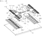
- FIG. 1 is a perspective view showing an embodiment of a phase shifter according to the present disclosure
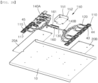
- FIGS. 2A and 2B are exploded perspective views of FIG. 1
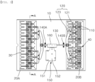
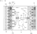
- FIG. 3 is a top view of FIG. 1
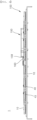
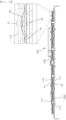
- FIG. 4 is a side view of FIG. 1 .
- a phase shifter 1 includes, as shown in FIGS. 1 to 4 , a base panel 10; fixed substrates 20A and 20B, each of which is stacked and fixed onto one side or another side of the base panel 10 and has a plurality of circuit patterns 30 printed on the top surface thereof; and a phase shift switching part 100 provided with a plurality of movable substrates 40 which are in contact with the plurality of circuit patterns 30 of the fixed substrates 20A and 20B, wherein the phase shift switching part is configured to reciprocate the plurality of movable substrates 40 within a predetermined distance in a horizontal direction on the base panel 10 to change the positions of the contact points of the movable substrates 40 with respect to the circuit patterns 30.
- the fixed substrates 20A and 20B may be fixed to one surface (top surface in the drawings) of the base panel 10.
- the pair of fixed substrates 20A and 20B may be arranged adjacent to one short side and the other short side of the base panel respectively to be spaced apart from each other.
- the fixed substrates 20A and 20B may be provided as ordinary printed circuit substrates, and the above-described plurality of circuit patterns 30 may be printed on one surface (upper surface in the drawings) using a method such as etching or the like.
- the plurality of circuit patterns 30 may be formed on the fixed substrates 20A and 20B to be spaced apart from each other in a number corresponding to the number of movable strip terminals 44 (which will be described later) formed on the lower surface of the plurality of movable substrates 40, and may be made of a material that is electrically coupled to the movable strip terminal 44.
- eight pairs of circuit patterns 30 may be provided on each of the fixed substrates 20A and 20B, and eight movable substrates 40 described above may also be provided to be movable on each of the fixed substrates 20A and 20B. Therefore, in cases where two fixed substrates 20A and 20B are provided on one base panel 10, a total of sixteen circuit patterns 30 can be printed, and a total of sixteen movable substrates 40 can also be provided.
- the plurality of circuit patterns 30 may be connected to at least one input port 30A and a plurality of output ports 30B-1 and 30B-2. Additionally, the plurality of circuit patterns 30 may share at least one input port 30A with each other, or each of the plurality of circuit patterns 30 may be provided with an input port 30A.
- Each circuit pattern 30 of the fixed substrates 20A and 20B may be coupled to the movable strip terminal 44 of the corresponding movable substrate 40, thereby forming a plurality of transmission lines.
- the signal received through the input port 30A may be transmitted to each of the output ports 30B-1 and 30B-2 through each transmission line implemented with each of the circuit patterns 30.
- the signal delivered to each of the output ports 30B-1 and 30B-2 may be transmitted to an antenna element (not shown), which is one of the components of each communication device, through an RF cable or RF connector.
- the movable strip terminals 44 provided on the lower surfaces of the movable substrates 40 are also moved while being in contact with the plurality of circuit patterns 30.
- the physical length of each transmission line can be shortened or lengthened, thereby enabling the adjustment of the phase difference between signals transmitted through the respective transmission lines.
- the base panel 10 may be made of Teflon material, which has a low loss rate in a high frequency environment.
- the material of the base panel 10 is not necessarily limited to this, but it is possible to form the base panel 10 with other materials.
- FIGS. 5A and 5B are a cross-sectional view (a) and a cutaway view (b) taken along line A-A of FIG. 3 , each also showing a partially enlarged view
- FIG. 6 is a perspective view representing the phase shift switching part in the structure of FIG. 1 .
- the phase shift switching part 100 may include a plurality of movable substrate installing parts 110 with end portions on which the plurality of movable substrates 40 are seated and installed, respectively, module rods 120 connecting the plurality of movable substrate installing parts 110 in module units, a movable rod 130 extending straight from the module rods 120 in a reciprocation moving direction, and a moving drive part 150 that moves the movable rod 130 in the reciprocation moving direction.
- the plurality of movable substrate installing parts 110 may be arranged such that a single movable substrate 40 is installed at a position corresponding to each of the plurality of circuit patterns 30, and each of the movable substrates 40 may be fitted to the bottom surface of each of the end portions of the plurality of movable substrate installing parts 110 via a pair of fixing protrusions 41.
- each of the pair of fixing protrusions 41 is provided with a protrusion having a diameter greater than that of a fixing hole 111 formed to penetrate the movable substrate installing part 110, so that it can fix the movable substrate 40 to the movable substrate installing part 110 by being forcedly fitted into the fixing hole 111, and since the length of the fixing protrusion 41 is formed to be larger than that of the fixing hole 111, the movable substrate 40 can be installed to be movable within the limit limited by the protrusion of the fixing protrusion 41 in the vertical direction.
- the protrusion of the fixing protrusion 41 may have a slit (not shown) of a predetermined depth formed at the distal end so that the protrusion can be deformed by an interference force when being inserted into the fixing hole 111, and so that the diameter of the protrusion of the fixing protrusion 41 can be reduced by the deformation thereof, enabling the smooth insertion thereof into the fixing hole 111 when being fitted into the fixing hole 111.
- an elastic member 43 which is provided as a leaf spring convexly protruding toward the lower surface of the movable substrate installing part 110, and due to the elastic support force of the elastic member 43, the movable substrate 40 can be always elastically supported toward the fixed substrate 20A or 20B on which the plurality of circuit patterns 30 are formed, so that the movable strip terminal 44 of the movable substrate 40 can be continuously in close contact with the circuit pattern 30 of the fixed substrate 20A or 20B.
- the plurality of movable substrate installing parts 110 may be connected to each other in each module by at least two module rods 120.
- the two movable substrate installing parts 110 may be together connected to one module rod 120.
- the module rod 120 may include module connection parts 121, each of which is branched and connected to three points of each of the two movable substrate installing parts 110, and an integrated connection part 123 which integrates and connects the respective module connection parts 121. To the center of the integrated connection part 123, the movable rod 130 may be connected.
- the movable substrates 40, the movable substrate installing parts 110, and the module rods 120 may be provided in each module on one side fixed substrate and the other side fixed substrate 20A and 20B, and one end and the other end of the movable rod 130 may be respectively connected to the centers of the integrated connection parts 123 of the module rods 120. Therefore, when the movable rod 130 is moved in the above-mentioned reciprocation moving direction, the movable substrates 40 on the one side fixed substrate and the other side fixed substrate 20A and 20B are moved in the same direction, so that the above-mentioned phase difference can be adjusted.
- the guide slot 115 may be formed to have a length that limits the change from the position where the transmission line is the shortest to the position where the transmission line is the longest when the movable substrate 40 changes the contact point position on the circuit pattern 30 described above.
- the description will be presented as two guide slots 115 being provided in each of the two module rods 120 to be spaced apart from each other. However, it is not necessary that only two guide slots 115 are formed in one module rod 120, and it is possible to form three or more slots in one module rod.
- a guide rod 117 fixed to the base panel 10 may be installed in each of the at least one guide slot 115.
- the guide rod 117 may penetrate the guide slot 115 in the up and down direction and be fixed to the base panel 10 via a screw, and it may be provided with an upper end portion having a countersunk head shape which has a diameter sufficient to support the edge of the guide slot 115.
- the guide rod 117 and the guide slot 115 can guide the reciprocation moving of the module rod 120 and the movable substrate installing part 110 according to the reciprocation horizontal moving of the movable rod 130, and at the same time, can prevent the module rod 120 and the movable substrate installing part 110 from being deviated or lifted excessively from the base panel 10.
- the movable substrate installing part 110 is elastically supported upward by the elastic member 43 installed between the movable substrate 40 and itself, and thus there may be a concern of causing the movable substrate installing part to be moved irregularly from the fixed substrate 20A or 20B, but as described above, the countersunk head-shaped guide rod 117 is supported on the edge of the guide slot 115, so that the movable substrate installing part 110, the module rod 120, and the movable rod 130 can be stably and horizontally maintained.
- At least one guide bracket 140A or 140B may be installed to prevent the movable rod 130 from being deviated and to guide the reciprocation moving of the movable rod.
- the guide brackets 140A and 140B may be provided such that both end portions of the movable rod 130 penetrate the guide brackets, and may be provided in a pair so as to support portions adjacent to the respective ends of the movable rod 130 penetrating the guide brackets.
- the guide brackets 140A and 140B may include one side guide bracket 140A provided such that one end of the movable rod 130 adjacent to one side fixed substrate 20A is installed therethrough, and the other side guide bracket 140B provided such that the other end of the movable rod 130 adjacent to the other side fixed substrate 20B is installed therethrough.
- the one side guide bracket 140A and the other side guide bracket 140B are coupled to the base panel 10 via screws, and serve to guide the reciprocation moving of the movable rod 130 through them in the horizontal direction.
- the one side guide bracket 140A and the other side guide bracket 140B may perform the function of preventing the entire module rods 120 including the movable substrate installing parts 110 from being excessively spaced from the one side fixed substrate 20A and the other side fixed substrate 20B by the elastic members 43 interposed between the movable substrates 40 and the movable substrate installing parts.
- the phase shift switching part 100 may further include a moving drive part 150 that moves the movable rod 130 horizontally in the reciprocation moving direction.
- the moving drive part 150 may include a drive motor 153 provided inside a gear box 151 and driven electrically, a set of reduction gears 155 to 159 that receives a driving force from the drive motor 153 and reduces the speed, and a rack gear part 160 having rack gear teeth 161 formed on one side thereof, and provided on the movable rod 130 such that one gear (pinion gear 159) of the set of reduction gears 155 to 159 meshes with the rack gear teeth 161.
- the rotation shaft 153c of the drive motor 153 may be disposed inside the gear box 151 in parallel to the movable rod 130, and a worm gear 154 having worm gear teeth may be coupled to the rotation shaft 153c of the drive motor 153.
- the set of reduction gears 155 to 159 may include a worm wheel gear 155 provided with worm wheel gear teeth to mesh with the worm gear teeth of the worm gear 154 coupled to the rotation shaft 153c of the drive motor 153, a pinion gear 159 meshed with the rack gear part 160 provided on the movable rod 130, and a gear group set between the worm wheel gear 155 and the pinion gear 159, in which a combination of at least three two-stage parallel gears 156 to 158 meshed with each other at various gear ratios reduces and transmits the driving force of the drive motor 153.
- the set of reduction gears 155 to 159 can reduce the driving force of the drive motor 153 to an appropriate reduction ratio by combining a plurality of gear ratios including the worm wheel gear 155 and the pinion gear 159, and so can precisely control the movement distance of the movable rod 130, and it is also possible to adjust the phase difference more precisely through controlling the movement distance of the movable rod 130.
- the drive motor 153 is preferably provided as a step motor capable of controlling rotation in one direction or the other direction.
- the principle of adjusting the phase difference by controlling the rotation of the drive motor 153 provided as a step motor will be described in more detail when describing the communication device including the phase shifter 1 according to an embodiment of the present disclosure.
- FIGS. 7A and 7B are top views of FIG. 1 , which visually show changes in the overlap length between the circuit pattern and the movable substrate before and after phase shift
- FIGS. 8A and 8B are top views of FIG. 1 , showing configurations before and after phase shifts corresponding to the maximum and minimum.
- phase shifter 1 may be included in a communication device capable of shifting the phase value to enable beamforming with improved gain (+3dB) through multiple antenna sub-arrays among the configurations of antenna devices that reflect MIMO (Multiple Input Multiple Output) technology.
- MIMO Multiple Input Multiple Output
- MIMO technology which is a technology that dramatically increases data transmission capacity by using multiple antenna sub-arrays, is a spatial multiplexing technique in which the transmitter transmits different data through respective transmission antennas, and the receiver distinguishes the received data through appropriate signal processing. Therefore, as the numbers of transmitting and receiving antennas increase simultaneously, channel capacity increases, allowing more data to be transmitted. For example, if the number of antennas is increased to ten, approximately 10 times the channel capacity is secured using the same frequency band compared to a single antenna system.
- the antenna device may arrange TRx modules (not shown) that perform transmitter and receiver functions in the up and down vertical direction (V) and in the left and right horizontal direction (H), and a plurality of antenna elements may be arranged to be electrically connected to each TRx module.
- the channel capacity built for each TRx module can be redefined with an "RF chain”, and can be redefined with an "antenna sub-array" as a group part of antenna elements in which a plurality of antenna elements are arranged for antenna beam forming.
- Multiple RF chains may be constructed in the V direction, and at this time, three or more antenna sub-arrays for each RF chain may be arranged in the V direction.
- each RF chain may be constructed through a transmission line to branch from one input terminal to two output terminals, and an antenna sub-array may be arranged at each output terminal.
- an antenna sub-array may be constructed, without being limited to this, so that the output phase difference realizes a linear phase value.
- the transmission line may be implemented in the form of the circuit patterns 30 printed on the one side fixed substrate 20A and the other side fixed substrate 20B, and the input terminal may be implemented as the input port 30A of a feeding signal, while the two output terminals may be implemented as the output ports 30B-1 and 30B-2 of the feeding signal, and the transmission line may have a structure in which power is fed while the physical length of the transmission line is changed by the movable strip terminal 44 of the movable substrate 40.
- the radiation beam of an antenna sub-array or the like radiating with a phase value shifted by the phase shifter 1 may be capable of implementing beam forming with a gain of +3 dB improved compared to the conventional case where the beam is radiated through an antenna sub-array for each RF chain instead of branching from the input terminal of each RF chain to two output terminals.
- the movable rod 130 is moved to the right in the drawing and the plurality of movable substrates 40 are simultaneously moved to the right, while the contact point positions can be changed to the right on the circuit patterns 30 to increase the lengths of the transmission lines, and the adjustment of the phase difference according to the contact point position is completed.
- the overlap length between the movable strip terminal 44 of the movable substrate 40 and the circuit pattern 30 may correspond to the reference notation "O1 (Overlap 1)" in FIG. 7A , and the length of the movable strip terminal 44 excluding the length corresponding to twice O1 may be an increment contributing to the existing transmission line.
- the overlap length between the movable strip terminal 44 of the movable substrate 40 and the circuit pattern 30 may correspond to the reference notation "O2 (Overlap 2)" in FIG. 7B , and the length of the movable strip terminal 44 excluding the length corresponding to twice O2 may be an increment contributing to the existing transmission line.
- the movable rod 130 has the reciprocation moving distance limited by the guide rod 117 provided in the above-described guide slot 115, and, as shown in FIGS. 8A and 8B , the movable rod can be designed to form the longest and shortest transmission lines on the circuit pattern 30 when being moved 0.8 mm to one side and the other side, respectively, under the assumption that the guide rod 117 is located at the center of the guide slot 115 (see reference notation "T" in FIGS. 8A and 8B ) .
- the communication device may be configured to include any one of the phase shifters 1 according to the embodiments described above.
- the phase shifter 1 according to an embodiment of the present disclosure may function as a single component included in a communication device that enables more efficient beam forming by changing the physical length of the transmission line.
- phase shifter 1 and the communication device including the same are arranged very slimly without taking up much space above the top of the base panel 10, and enable the horizontal reciprocation moving, so that they provide such an advantage that the phase difference can be precisely adjusted, maximizing the space utilization of a product.
- the present disclosure provides the phase shifter and the communication device including the same, which can be miniaturized and weight reduced, which enable the precise phase difference adjustment since the set of reduction gears is equipped thereto so as to precisely reciprocate and horizontally move the movable rod, and which can maximize the space utilization of the product since the phase shift switching part can be placed slimly on the base panel.
Landscapes
- Engineering & Computer Science (AREA)
- General Engineering & Computer Science (AREA)
- Mechanical Engineering (AREA)
- Waveguide Switches, Polarizers, And Phase Shifters (AREA)
Abstract
Description
- The present disclosure relates to a phase shifter and a communication device including the same, and more particularly to a phase shifter and a communication device including the same, which minimize the height from one surface of a fixed substrate to improve the space utilization of an antenna device, and which reduce the overall weight.
- Antenna devices are most efficient in terms of coverage when they form beams in the horizontal direction, but it is necessary sometimes to adjust the beam angle in the vertical direction for a reason such as interference, loss or the like. In this case, the beam angle of the antenna device is adjusted in the vertical direction through a mechanical beam tilting method or an electrical beam tilting method.
- The mechanical beam tilting method is one in which the beam angle is adjusted by directly installing the antenna device at a downward angle. Although it is a simple method, this method is disadvantageously somewhat cumbersome for various reasons, such as workers visiting the site, turning off the power during work and the like.
- The electrical beam tilting method is based on a multi line phase shifter (MLPS). Specifically, according to the electrical beam tilting method, the beam angle is adjusted by feeding signals with different phases to a plurality of vertically arranged radiating elements.
- In order to implement the electrical beam tilting method, the antenna device may be provided with a phase shifter. The phase shifter delays the input signal appropriately so that a phase difference occurs between the input signal and the output signal. At this time, the delay of the input signal can be implemented by changing the length of a transmission line or changing the signal transmission speed within the transmission line.
-
Korean Unexamined Patent Application Publication No. 2010-0122005 Patent Document 1 has a disadvantage in that space efficiency is reduced because the fixed substrate and the movable substrate are provided only on one side surface of the phase shifter. - Meanwhile, recently, multi-band frequency antenna devices capable of servicing various bands have been widely used as base stations or repeaters in mobile communication systems. The multi-band antenna devices are required to individually adjust the phases of multiple band frequencies. Therefore, the number of phase shifters provided in the antenna device may increase, and accordingly, the phase shifters need to be miniaturized and weight reduced.
- The present disclosure was conceived to solve the above-described technical problems, and its object is to provide a miniaturized and weight reduced phase shifter and a communication device including the same.
- In addition, another object of the present disclosure is to provide a phase shifter and a communication device including the same, which enable the precise phase difference adjustment since a set of reduction gears is equipped thereto so as to precisely reciprocate and horizontally move a movable rod, and which can maximize the space utilization of the product since a phase shift switching part can be placed slimly on a base panel.
- The technical drawbacks which this disclosure addresses are not limited to the aforementioned ones, but unmentioned other technical drawbacks which can be solved by this disclosure will become apparent to those skilled in the art from the description below.
- One embodiment of a phase shifter according to the present disclosure includes a base panel; a fixed substrate which is laminated and fixed on one side or another side on the base panel and has a plurality of circuit patterns printed on the top surface thereof; and a phase shift switching part provided with a plurality of movable substrates including movable strip terminals which are in contact with the plurality of circuit patterns of the fixed substrate, wherein the phase shift switching part is configured to reciprocate the plurality of movable substrates within a predetermined distance in a horizontal direction on the base panel to change the positions of contact points of the movable substrates with respect to the circuit patterns, and wherein the phase shift switching part moves the plurality of movable substrates while always elastically supporting the plurality of movable substrates toward the circuit patterns.
- Here, the plurality of circuit patterns may be printed on the fixed substrate in a form in which the length of a transmission line is changed according to a change in the contact point position of the movable substrate.
- Also, the plurality of circuit patterns may be formed to branch from one input terminal to two output terminals, and a movable strip terminal of the movable substrate may change the length of the transmission line leading to the two branched output terminals.
- Additionally, the phase shifter may include a plurality of movable substrate installing parts with end portions on which the plurality of movable substrates are seated and installed, respectively; a module rod connecting the plurality of movable substrate installing parts in module units; a movable rod extending straight from the module rod in the reciprocation moving direction; and a moving drive part which moves the movable rod in the reciprocation moving direction.
- Further, the fixed substrate may be distributively disposed as one side fixed substrate and another side fixed substrate on both opposite sides of the moving drive part located in the central region of the base panel in the reciprocation moving direction, wherein the plurality of movable substrate installing parts and the module rods may be provided adjacent to the one side fixed substrate and said another side fixed substrate, respectively, and wherein the movable rod may simultaneously receive a driving force from the moving drive part, and simultaneously move the plurality of movable substrate installing parts in the same direction.
- In addition, an elastic member may be interposed between the plurality of movable substrate installing parts and the movable substrate to elastically support the movable substrate toward the circuit pattern.
- Further, the elastic member may include a leaf spring.
- Additionally, the moving drive part may include a drive motor driven electrically; a set of reduction gears that receives a driving force from the drive motor and reduces speed; and a rack gear part having rack gear teeth formed on one side thereof, and provided on the movable rod such that one gear of the set of reduction gears meshes with the rack gear teeth.
- Further, the drive motor may be provided as a step motor capable of controlling rotation in one direction or another direction.
- Further, the set of reduction gears may be a combination of a plurality of parallel gears meshed with each other in various combinations of gear ratios, and be provided in a gear box.
- Further, one gear of the combination of the plurality of parallel gears may be provided as a worm wheel gear including worm wheel gear teeth provided to mesh with a worm gear coupled to the rotation shaft of the drive motor.
- Further, on the base panel, at least one guide bracket may be installed to prevent the movable rod from being deviated and to guide the reciprocation moving of the movable rod.
- One embodiment of the communication device according to the present disclosure may include the above-described phase shifter.
- According to the phase shifter and the communication device including the same according to the present disclosure, the following various effects can be achieved.
- First, since the set of reduction gears is provided to precisely reciprocate and horizontally move the movable rod, it is possible to create the effect of precise phase difference adjustment.
- Second, since the phase shift switching part can be placed slimly on the base panel, it is possible to create the effect of maximizing the space utilization of the product.
-
-
FIG. 1 is a perspective view showing an embodiment of a phase shifter according to the present disclosure, -
FIGS. 2A and2B are exploded perspective views ofFIG. 1 , -
FIG. 3 is a top view ofFIG. 1 , and -
FIG. 4 is a side view ofFIG. 1 , -
FIGS. 5A and5B are a cross-sectional view (a) and a cutaway view (b) taken along line A-A ofFIG. 3 , each also showing a partially enlarged view, and -
FIG. 6 is a perspective view representing the phase shift switching part in the structure ofFIG. 1 , -
FIGS. 7A and7B are top views ofFIG. 1 , which visually show changes in the overlap length between the circuit pattern and the movable substrate before and after phase shift, and -
FIGS. 8A and8B are top views ofFIG. 1 , showing configurations before and after phase shifts corresponding to the maximum and minimum. -
1: Phase shifter 10: Base panel 20A, 20B: Fixed substrate 30: Circuit pattern 40: Movable substrate 41: Fixing protrusion 43: Elastic member 100: Phase shift switching part 110: Movable substrate installing part 111: Fixing hole 115: Guide slot 117: Guide rod 120: Module rod 121: Module connection part 123: Integrated connection part 130: Movable rod 140A, 140B: Guide bracket 150: Moving drive part 151: Gear box 152: Box cover 153: Drive motor 153c: Rotation shaft 154: Worm gear 155 - 159: Set of reduction gears 155: Worm wheel gear 158: Parallel gear combination 159: Pinion gear 160: Rack gear part - Hereinafter, a phase shifter according to an embodiment of the present disclosure will be described in detail with reference to the accompanying drawings.
- In adding reference numerals to components of each drawing, it should be noted that the same components have the same reference numerals as much as possible even if they are shown on different drawings. In addition, in describing an embodiment of the present disclosure, if it is determined that a detailed description of a related known configuration or function may prevent the understanding of the embodiment of the present disclosure, the detailed description thereof will be omitted.
- In describing the components of an embodiment of the present disclosure, terms such as first, second, A, B, (a), (b), and the like may be used. These terms do not limit the nature, sequence, order or the like of the corresponding components. Further, unless otherwise defined, all terms used herein, including technical or scientific terms, have the same meaning as commonly understood by a person of ordinary skill in the art to which the present disclosure pertains. Terms, such as those defined in a commonly used dictionary, should be interpreted as having a meaning that is consistent with the meaning in the context of the related technology, and will not to be interpreted in an idealized or excessively formal sense unless expressly so defined in this application.
-
FIG. 1 is a perspective view showing an embodiment of a phase shifter according to the present disclosure,FIGS. 2A and2B are exploded perspective views ofFIG. 1 ,FIG. 3 is a top view ofFIG. 1 , andFIG. 4 is a side view ofFIG. 1 . - A
phase shifter 1 according to an embodiment of the present disclosure includes, as shown inFIGS. 1 to 4 , abase panel 10; fixedsubstrates base panel 10 and has a plurality ofcircuit patterns 30 printed on the top surface thereof; and a phaseshift switching part 100 provided with a plurality ofmovable substrates 40 which are in contact with the plurality ofcircuit patterns 30 of the fixedsubstrates movable substrates 40 within a predetermined distance in a horizontal direction on thebase panel 10 to change the positions of the contact points of themovable substrates 40 with respect to thecircuit patterns 30. - Referring to
FIGS. 1 to 4 , the fixedsubstrates base panel 10. In this regard, when it is assumed that thebase panel 10 is provided in a substantially rectangular parallelepiped shape, the pair of fixedsubstrates - The fixed
substrates circuit patterns 30 may be printed on one surface (upper surface in the drawings) using a method such as etching or the like. The plurality ofcircuit patterns 30 may be formed on the fixedsubstrates movable substrates 40, and may be made of a material that is electrically coupled to themovable strip terminal 44. - Here, eight pairs of
circuit patterns 30 may be provided on each of the fixedsubstrates movable substrates 40 described above may also be provided to be movable on each of the fixedsubstrates substrates base panel 10, a total of sixteencircuit patterns 30 can be printed, and a total of sixteenmovable substrates 40 can also be provided. - The plurality of
circuit patterns 30 may be connected to at least oneinput port 30A and a plurality ofoutput ports 30B-1 and 30B-2. Additionally, the plurality ofcircuit patterns 30 may share at least oneinput port 30A with each other, or each of the plurality ofcircuit patterns 30 may be provided with aninput port 30A. - Each
circuit pattern 30 of the fixedsubstrates movable strip terminal 44 of the correspondingmovable substrate 40, thereby forming a plurality of transmission lines. - The signal received through the
input port 30A may be transmitted to each of theoutput ports 30B-1 and 30B-2 through each transmission line implemented with each of thecircuit patterns 30. The signal delivered to each of theoutput ports 30B-1 and 30B-2 may be transmitted to an antenna element (not shown), which is one of the components of each communication device, through an RF cable or RF connector. - When the
movable substrates 40 are moved on the one surfaces (upper surfaces) of the fixedsubstrates movable strip terminals 44 provided on the lower surfaces of themovable substrates 40 are also moved while being in contact with the plurality ofcircuit patterns 30. In this way, by changing the contact positions of themovable strip terminals 44 of themovable substrates 40 with respect to the plurality ofcircuit patterns 30, the physical length of each transmission line can be shortened or lengthened, thereby enabling the adjustment of the phase difference between signals transmitted through the respective transmission lines. - The
base panel 10 may be made of Teflon material, which has a low loss rate in a high frequency environment. However, the material of thebase panel 10 is not necessarily limited to this, but it is possible to form thebase panel 10 with other materials. -
FIGS. 5A and5B are a cross-sectional view (a) and a cutaway view (b) taken along line A-A ofFIG. 3 , each also showing a partially enlarged view, andFIG. 6 is a perspective view representing the phase shift switching part in the structure ofFIG. 1 . - Referring to
FIGS. 1 to 4 , the phaseshift switching part 100 may include a plurality of movablesubstrate installing parts 110 with end portions on which the plurality ofmovable substrates 40 are seated and installed, respectively,module rods 120 connecting the plurality of movablesubstrate installing parts 110 in module units, amovable rod 130 extending straight from themodule rods 120 in a reciprocation moving direction, and a movingdrive part 150 that moves themovable rod 130 in the reciprocation moving direction. - More specifically, as shown in
FIGS. 2A and2B , the plurality of movablesubstrate installing parts 110 may be arranged such that a singlemovable substrate 40 is installed at a position corresponding to each of the plurality ofcircuit patterns 30, and each of themovable substrates 40 may be fitted to the bottom surface of each of the end portions of the plurality of movablesubstrate installing parts 110 via a pair of fixingprotrusions 41. - At this time, the upper end portion of each of the pair of fixing
protrusions 41 is provided with a protrusion having a diameter greater than that of a fixinghole 111 formed to penetrate the movablesubstrate installing part 110, so that it can fix themovable substrate 40 to the movablesubstrate installing part 110 by being forcedly fitted into the fixinghole 111, and since the length of the fixingprotrusion 41 is formed to be larger than that of the fixinghole 111, themovable substrate 40 can be installed to be movable within the limit limited by the protrusion of the fixingprotrusion 41 in the vertical direction. - The protrusion of the fixing
protrusion 41 may have a slit (not shown) of a predetermined depth formed at the distal end so that the protrusion can be deformed by an interference force when being inserted into the fixinghole 111, and so that the diameter of the protrusion of the fixingprotrusion 41 can be reduced by the deformation thereof, enabling the smooth insertion thereof into the fixinghole 111 when being fitted into the fixinghole 111. - In this regard, on the upper surface of the
movable substrate 40, there may be prepared anelastic member 43 which is provided as a leaf spring convexly protruding toward the lower surface of the movablesubstrate installing part 110, and due to the elastic support force of theelastic member 43, themovable substrate 40 can be always elastically supported toward the fixedsubstrate circuit patterns 30 are formed, so that themovable strip terminal 44 of themovable substrate 40 can be continuously in close contact with thecircuit pattern 30 of the fixedsubstrate - Meanwhile, as shown in
FIGS. 2A and2B , the plurality of movablesubstrate installing parts 110 may be connected to each other in each module by at least twomodule rods 120. For example, in cases where a total of eightmovable substrates 40 are provided on each of the fixedsubstrates substrate installing parts 110, on each of which fourmovable substrates 40 are installed in each module, and the two movablesubstrate installing parts 110 may be together connected to onemodule rod 120. - The
module rod 120 may includemodule connection parts 121, each of which is branched and connected to three points of each of the two movablesubstrate installing parts 110, and anintegrated connection part 123 which integrates and connects the respectivemodule connection parts 121. To the center of theintegrated connection part 123, themovable rod 130 may be connected. - In this way, the
movable substrates 40, the movablesubstrate installing parts 110, and themodule rods 120 may be provided in each module on one side fixed substrate and the other side fixedsubstrate movable rod 130 may be respectively connected to the centers of theintegrated connection parts 123 of themodule rods 120. Therefore, when themovable rod 130 is moved in the above-mentioned reciprocation moving direction, themovable substrates 40 on the one side fixed substrate and the other side fixedsubstrate - Meanwhile, in the
module rod 120, by cutting it in the up and down direction, at least oneguide slot 115 may be formed. Theguide slot 115 may be formed to have a length that limits the change from the position where the transmission line is the shortest to the position where the transmission line is the longest when themovable substrate 40 changes the contact point position on thecircuit pattern 30 described above. In one embodiment of the present disclosure, the description will be presented as twoguide slots 115 being provided in each of the twomodule rods 120 to be spaced apart from each other. However, it is not necessary that only twoguide slots 115 are formed in onemodule rod 120, and it is possible to form three or more slots in one module rod. - In each of the at least one
guide slot 115, aguide rod 117 fixed to thebase panel 10 may be installed. Theguide rod 117 may penetrate theguide slot 115 in the up and down direction and be fixed to thebase panel 10 via a screw, and it may be provided with an upper end portion having a countersunk head shape which has a diameter sufficient to support the edge of theguide slot 115. - Accordingly, the
guide rod 117 and theguide slot 115 can guide the reciprocation moving of themodule rod 120 and the movablesubstrate installing part 110 according to the reciprocation horizontal moving of themovable rod 130, and at the same time, can prevent themodule rod 120 and the movablesubstrate installing part 110 from being deviated or lifted excessively from thebase panel 10. - In this case, the movable
substrate installing part 110 is elastically supported upward by theelastic member 43 installed between themovable substrate 40 and itself, and thus there may be a concern of causing the movable substrate installing part to be moved irregularly from the fixedsubstrate guide rod 117 is supported on the edge of theguide slot 115, so that the movablesubstrate installing part 110, themodule rod 120, and themovable rod 130 can be stably and horizontally maintained. - In this regard, on the
base panel 10, at least oneguide bracket movable rod 130 from being deviated and to guide the reciprocation moving of the movable rod. Theguide brackets movable rod 130 penetrate the guide brackets, and may be provided in a pair so as to support portions adjacent to the respective ends of themovable rod 130 penetrating the guide brackets. - More specifically, the
guide brackets side guide bracket 140A provided such that one end of themovable rod 130 adjacent to one side fixedsubstrate 20A is installed therethrough, and the otherside guide bracket 140B provided such that the other end of themovable rod 130 adjacent to the other side fixedsubstrate 20B is installed therethrough. - The one
side guide bracket 140A and the otherside guide bracket 140B are coupled to thebase panel 10 via screws, and serve to guide the reciprocation moving of themovable rod 130 through them in the horizontal direction. - In addition, the one
side guide bracket 140A and the otherside guide bracket 140B may perform the function of preventing theentire module rods 120 including the movablesubstrate installing parts 110 from being excessively spaced from the one side fixedsubstrate 20A and the other side fixedsubstrate 20B by theelastic members 43 interposed between themovable substrates 40 and the movable substrate installing parts. - As shown in
FIG. 6 , the phaseshift switching part 100 may further include a movingdrive part 150 that moves themovable rod 130 horizontally in the reciprocation moving direction. - As shown in
FIG. 6 , the movingdrive part 150 may include adrive motor 153 provided inside agear box 151 and driven electrically, a set of reduction gears 155 to 159 that receives a driving force from thedrive motor 153 and reduces the speed, and arack gear part 160 havingrack gear teeth 161 formed on one side thereof, and provided on themovable rod 130 such that one gear (pinion gear 159) of the set of reduction gears 155 to 159 meshes with therack gear teeth 161. - The rotation shaft 153c of the
drive motor 153 may be disposed inside thegear box 151 in parallel to themovable rod 130, and aworm gear 154 having worm gear teeth may be coupled to the rotation shaft 153c of thedrive motor 153. - Meanwhile, the set of reduction gears 155 to 159 may include a
worm wheel gear 155 provided with worm wheel gear teeth to mesh with the worm gear teeth of theworm gear 154 coupled to the rotation shaft 153c of thedrive motor 153, apinion gear 159 meshed with therack gear part 160 provided on themovable rod 130, and a gear group set between theworm wheel gear 155 and thepinion gear 159, in which a combination of at least three two-stage parallel gears 156 to 158 meshed with each other at various gear ratios reduces and transmits the driving force of thedrive motor 153. - In this way, the set of reduction gears 155 to 159 can reduce the driving force of the
drive motor 153 to an appropriate reduction ratio by combining a plurality of gear ratios including theworm wheel gear 155 and thepinion gear 159, and so can precisely control the movement distance of themovable rod 130, and it is also possible to adjust the phase difference more precisely through controlling the movement distance of themovable rod 130. - In this regard, the
drive motor 153 is preferably provided as a step motor capable of controlling rotation in one direction or the other direction. The principle of adjusting the phase difference by controlling the rotation of thedrive motor 153 provided as a step motor will be described in more detail when describing the communication device including thephase shifter 1 according to an embodiment of the present disclosure. -
FIGS. 7A and7B are top views ofFIG. 1 , which visually show changes in the overlap length between the circuit pattern and the movable substrate before and after phase shift, andFIGS. 8A and8B are top views ofFIG. 1 , showing configurations before and after phase shifts corresponding to the maximum and minimum. - Although not shown in the drawings, the
phase shifter 1 according to an embodiment of the present disclosure may be included in a communication device capable of shifting the phase value to enable beamforming with improved gain (+3dB) through multiple antenna sub-arrays among the configurations of antenna devices that reflect MIMO (Multiple Input Multiple Output) technology. - MIMO technology, which is a technology that dramatically increases data transmission capacity by using multiple antenna sub-arrays, is a spatial multiplexing technique in which the transmitter transmits different data through respective transmission antennas, and the receiver distinguishes the received data through appropriate signal processing. Therefore, as the numbers of transmitting and receiving antennas increase simultaneously, channel capacity increases, allowing more data to be transmitted. For example, if the number of antennas is increased to ten, approximately 10 times the channel capacity is secured using the same frequency band compared to a single antenna system.
- In particular, the antenna device may arrange TRx modules (not shown) that perform transmitter and receiver functions in the up and down vertical direction (V) and in the left and right horizontal direction (H), and a plurality of antenna elements may be arranged to be electrically connected to each TRx module. Here, the channel capacity built for each TRx module can be redefined with an "RF chain", and can be redefined with an "antenna sub-array" as a group part of antenna elements in which a plurality of antenna elements are arranged for antenna beam forming.
- Multiple RF chains may be constructed in the V direction, and at this time, three or more antenna sub-arrays for each RF chain may be arranged in the V direction.
- Here, each RF chain may be constructed through a transmission line to branch from one input terminal to two output terminals, and an antenna sub-array may be arranged at each output terminal. However, it should be noted that a separate additional antenna sub-array can be constructed, without being limited to this, so that the output phase difference realizes a linear phase value.
- In particular, in the
phase shifter 1 according to an embodiment of the present disclosure, the transmission line may be implemented in the form of thecircuit patterns 30 printed on the one side fixedsubstrate 20A and the other side fixedsubstrate 20B, and the input terminal may be implemented as theinput port 30A of a feeding signal, while the two output terminals may be implemented as theoutput ports 30B-1 and 30B-2 of the feeding signal, and the transmission line may have a structure in which power is fed while the physical length of the transmission line is changed by themovable strip terminal 44 of themovable substrate 40. - In this way, the radiation beam of an antenna sub-array or the like radiating with a phase value shifted by the
phase shifter 1 according to an embodiment of the present disclosure may be capable of implementing beam forming with a gain of +3 dB improved compared to the conventional case where the beam is radiated through an antenna sub-array for each RF chain instead of branching from the input terminal of each RF chain to two output terminals. - Hereinafter, the process of changing the physical length of the transmission line using the
phase shifter 1 according to an embodiment of the present disclosure will be briefly described with reference to the accompanying drawings (particularly,FIGS. 7A to 8B ). - For example, as shown in
FIG. 7A , when thedrive motor 153 is rotated in one side, themovable rod 130 is moved to the right in the drawing and the plurality ofmovable substrates 40 are simultaneously moved to the right, while the contact point positions can be changed to the right on thecircuit patterns 30 to increase the lengths of the transmission lines, and the adjustment of the phase difference according to the contact point position is completed. - At this time, the overlap length between the
movable strip terminal 44 of themovable substrate 40 and thecircuit pattern 30 may correspond to the reference notation "O1 (Overlap 1)" inFIG. 7A , and the length of themovable strip terminal 44 excluding the length corresponding to twice O1 may be an increment contributing to the existing transmission line. - Additionally, as shown in
FIG. 7B , when thedrive motor 153 is rotated in the other side, themovable rod 130 is moved to the left in the drawing and the plurality ofmovable substrates 40 are simultaneously moved to the left, while the contact point positions can be changed to the left on thecircuit patterns 30 to increase the lengths of the transmission lines, and the adjustment of the phase difference according to the contact point position is completed. - At this time, the overlap length between the
movable strip terminal 44 of themovable substrate 40 and thecircuit pattern 30 may correspond to the reference notation "O2 (Overlap 2)" inFIG. 7B , and the length of themovable strip terminal 44 excluding the length corresponding to twice O2 may be an increment contributing to the existing transmission line. - For reference, the
movable rod 130 has the reciprocation moving distance limited by theguide rod 117 provided in the above-describedguide slot 115, and, as shown inFIGS. 8A and8B , the movable rod can be designed to form the longest and shortest transmission lines on thecircuit pattern 30 when being moved 0.8 mm to one side and the other side, respectively, under the assumption that theguide rod 117 is located at the center of the guide slot 115 (see reference notation "T" inFIGS. 8A and8B ) . - The communication device according to an embodiment of the present disclosure may be configured to include any one of the
phase shifters 1 according to the embodiments described above. For example, as described above, in implementing the beam forming through multiple antenna sub-arrays, thephase shifter 1 according to an embodiment of the present disclosure may function as a single component included in a communication device that enables more efficient beam forming by changing the physical length of the transmission line. - In this way, the
phase shifter 1 and the communication device including the same according to an embodiment of the present disclosure are arranged very slimly without taking up much space above the top of thebase panel 10, and enable the horizontal reciprocation moving, so that they provide such an advantage that the phase difference can be precisely adjusted, maximizing the space utilization of a product. - In the above, the phase shifter and the communication device including the same according to an embodiment of the present disclosure have been described in detail with reference to the accompanying drawings. However, it should be taken for granted that the embodiments of the present disclosure are not necessarily limited to the above-described embodiment, and various modifications and implementation within the equivalent scope are possible by those skilled in the art to which the present disclosure pertains. Therefore, it should be understood that the true scope of the right of the present disclosure is determined by the claims described later.
- The present disclosure provides the phase shifter and the communication device including the same, which can be miniaturized and weight reduced, which enable the precise phase difference adjustment since the set of reduction gears is equipped thereto so as to precisely reciprocate and horizontally move the movable rod, and which can maximize the space utilization of the product since the phase shift switching part can be placed slimly on the base panel.
Claims (13)
- A phase shifter comprising:a base panel;a fixed substrate which is laminated and fixed on one side or another side on the base panel and has a plurality of circuit patterns printed on the top surface thereof; anda phase shift switching part provided with a plurality of movable substrates including movable trip terminals which are in contact with the plurality of circuit patterns of the fixed substrate, wherein the phase shift switching part is configured to reciprocate the plurality of movable substrates within a predetermined distance in a horizontal direction on the base panel to change the positions of contact points of the movable substrates with respect to the circuit patterns,wherein the phase shift switching part moves the plurality of movable substrates while always elastically supporting the plurality of movable substrates toward the circuit patterns.
- The phase shifter of claim 1, wherein the plurality of circuit patterns are printed on the fixed substrate in a form in which the length of a transmission line is changed according to a change in the contact point position of the movable substrate.
- The phase shifter of claim 2, wherein the plurality of circuit patterns are formed to branch from one input terminal to two output terminals, and
wherein a movable strip terminal of the movable substrate changes the length of the transmission line leading to the two branched output terminals. - The phase shifter of claim 1, wherein the phase shift switching part includes:a plurality of movable substrate installing parts with end portions on which the plurality of movable substrates are seated and installed, respectively;a module rod connecting the plurality of movable substrate installing parts in module units;a movable rod extending straight from the module rod in the reciprocation moving direction; anda moving drive part which moves the movable rod in the reciprocation moving direction.
- The phase shifter of claim 4, wherein the fixed substrate is distributively disposed as one side fixed substrate and another side fixed substrate on both opposite sides of the moving drive part located in the central region of the base panel in the reciprocation moving direction,wherein the plurality of movable substrate installing parts and the module rods are provided adjacent to the one side fixed substrate and said another side fixed substrate, respectively, andwherein the movable rod receives a driving force from the moving drive part, and simultaneously moves the plurality of movable substrate installing parts in the same direction.
- The phase shifter of claim 4,
wherein an elastic member is interposed between the plurality of movable substrate installing parts and the movable substrate to elastically support the movable substrate toward the circuit pattern. - The phase shifter of claim 6, wherein the elastic member includes a leaf spring.
- The phase shifter of claim 4, wherein the moving drive part includes:a drive motor driven electrically;a set of reduction gears that receives a driving force from the drive motor and reduces speed; anda rack gear part having rack gear teeth formed on one side thereof, and provided on the movable rod such that one gear of the set of reduction gears meshes with the rack gear teeth.
- The phase shifter of claim 8, wherein the drive motor is provided as a step motor capable of controlling rotation in one direction or another direction.
- The phase shifter of claim 8, wherein the set of reduction gears includes a combination of a plurality of parallel gears meshed with each other in various combinations of gear ratios, and is provided in a gear box.
- The phase shifter of claim 10, wherein the set of reduction gears includes a worm wheel gear including worm wheel gear teeth provided to mesh with a worm gear coupled to the rotation shaft of the drive motor.
- The phase shifter of claim 4, wherein on the base panel, at least one guide bracket is installed to prevent the movable rod from being deviated and to guide the reciprocation moving of the movable rod.
- A communication device including a phase shifter according to any one of claims 1 to 5.
Applications Claiming Priority (2)
| Application Number | Priority Date | Filing Date | Title |
|---|---|---|---|
| KR20210089916 | 2021-07-08 | ||
| PCT/KR2022/009857 WO2023282665A1 (en) | 2021-07-08 | 2022-07-07 | Phase shifter and communication device including same |
Publications (2)
| Publication Number | Publication Date |
|---|---|
| EP4369520A1 true EP4369520A1 (en) | 2024-05-15 |
| EP4369520A4 EP4369520A4 (en) | 2025-07-23 |
Family
ID=85106681
Family Applications (1)
| Application Number | Title | Priority Date | Filing Date |
|---|---|---|---|
| EP22838017.6A Pending EP4369520A4 (en) | 2021-07-08 | 2022-07-07 | PHASE SHIFTER AND COMMUNICATION DEVICE THEREFOR |
Country Status (3)
| Country | Link |
|---|---|
| EP (1) | EP4369520A4 (en) |
| KR (1) | KR20230010169A (en) |
| CN (1) | CN117999703A (en) |
Families Citing this family (3)
| Publication number | Priority date | Publication date | Assignee | Title |
|---|---|---|---|---|
| WO2024205382A1 (en) * | 2023-03-29 | 2024-10-03 | 주식회사 케이엠더블유 | Phase shifter for antenna device |
| KR102901851B1 (en) | 2023-03-29 | 2025-12-19 | 주식회사 케이엠더블유 | Phase shifter of antenna apparatus |
| CN121548920A (en) * | 2023-08-08 | 2026-02-17 | 株式会社Kmw | Antenna device |
Family Cites Families (6)
| Publication number | Priority date | Publication date | Assignee | Title |
|---|---|---|---|---|
| JP2001237603A (en) * | 2000-02-23 | 2001-08-31 | Mitsubishi Electric Corp | Phase shifter |
| KR101567882B1 (en) | 2009-05-11 | 2015-11-12 | 주식회사 케이엠더블유 | Multiple phase shifter for vertical beam tilt control antenna |
| US20110140805A1 (en) * | 2009-12-16 | 2011-06-16 | Wha Yu Industrial Co., Ltd. | Phase shifter |
| US9325043B2 (en) * | 2013-07-26 | 2016-04-26 | Alcatel-Lucent Shanghai Bell Co., Ltd. | Phase shifting circuit including an elongated conductive path covered by a metal sheet having stand-off feet and also including a slidable tuning member |
| KR102561222B1 (en) * | 2018-07-11 | 2023-07-28 | 주식회사 케이엠더블유 | Phase shifter |
| CN112803163B (en) * | 2020-12-31 | 2022-05-03 | 华南理工大学 | Phase shift circuit, phase shifter and antenna |
-
2022
- 2022-07-07 KR KR1020220083480A patent/KR20230010169A/en active Pending
- 2022-07-07 EP EP22838017.6A patent/EP4369520A4/en active Pending
- 2022-07-07 CN CN202280048132.4A patent/CN117999703A/en active Pending
Also Published As
| Publication number | Publication date |
|---|---|
| EP4369520A4 (en) | 2025-07-23 |
| CN117999703A (en) | 2024-05-07 |
| KR20230010169A (en) | 2023-01-18 |
Similar Documents
| Publication | Publication Date | Title |
|---|---|---|
| EP4369520A1 (en) | Phase shifter and communication device including same | |
| US20240145913A1 (en) | Phase shifter and communication device including same | |
| EP3698436B1 (en) | Broadband stacked patch radiating elements and related phased array antennas | |
| US6963314B2 (en) | Dynamically variable beamwidth and variable azimuth scanning antenna | |
| US11316258B2 (en) | Massive MIMO (mMIMO) antenna with phase shifter and radio signal phase synchronization | |
| US20200052398A1 (en) | Beam squint remediation by switchable complex impedance in a broadband phased-array antenna system | |
| EP2430700B1 (en) | Multi-line phase shifter for vertical beam tilt-controlled antenna | |
| US6956537B2 (en) | Co-located antenna array for passive beam forming | |
| US11264732B2 (en) | Antenna module and communication apparatus | |
| KR20060109892A (en) | Phased Array Antenna System with Controllable Electrical Tilt | |
| CA2533308A1 (en) | Vertical electrical downtilt antenna | |
| US6661374B2 (en) | Base transceiver station having multibeam controllable antenna system | |
| WO2008124027A1 (en) | Dual stagger off settable azimuth beam width controlled antenna for wireless network | |
| US20240275067A1 (en) | Antenna and base station | |
| US20250219287A1 (en) | Ret assemblies providing synchronized phase shift of phase shifters for base station antennas | |
| US20250226578A1 (en) | Phase shifter and antenna device comprising same | |
| WO2019082447A1 (en) | Antenna | |
| US10749250B2 (en) | Multi-layer phase shifter driving device and related remote electronic tilt systems and antennas | |
| US20230344100A1 (en) | Phase shifter | |
| US20260058364A1 (en) | Phase converting apparatus | |
| US20260051655A1 (en) | Phase shifter | |
| EP4564611A1 (en) | Antenna apparatus and communication device | |
| EP4508719A1 (en) | Base station antennas having metal tuning elements that move in response to changes in a remote electronic tilt setting |
Legal Events
| Date | Code | Title | Description |
|---|---|---|---|
| STAA | Information on the status of an ep patent application or granted ep patent |
Free format text: STATUS: THE INTERNATIONAL PUBLICATION HAS BEEN MADE |
|
| PUAI | Public reference made under article 153(3) epc to a published international application that has entered the european phase |
Free format text: ORIGINAL CODE: 0009012 |
|
| STAA | Information on the status of an ep patent application or granted ep patent |
Free format text: STATUS: REQUEST FOR EXAMINATION WAS MADE |
|
| 17P | Request for examination filed |
Effective date: 20240103 |
|
| AK | Designated contracting states |
Kind code of ref document: A1 Designated state(s): AL AT BE BG CH CY CZ DE DK EE ES FI FR GB GR HR HU IE IS IT LI LT LU LV MC MK MT NL NO PL PT RO RS SE SI SK SM TR |
|
| DAV | Request for validation of the european patent (deleted) | ||
| DAX | Request for extension of the european patent (deleted) | ||
| REG | Reference to a national code |
Ref country code: DE Ref legal event code: R079 Free format text: PREVIOUS MAIN CLASS: H01Q0003360000 Ipc: H01P0001180000 |
|
| A4 | Supplementary search report drawn up and despatched |
Effective date: 20250623 |
|
| RIC1 | Information provided on ipc code assigned before grant |
Ipc: H01P 1/18 20060101AFI20250616BHEP Ipc: H01Q 3/32 20060101ALI20250616BHEP Ipc: H01Q 21/28 20060101ALN20250616BHEP |