EP4369445A1 - Fuel cell composite sheet and fuel cell composite sheet production method - Google Patents
Fuel cell composite sheet and fuel cell composite sheet production method Download PDFInfo
- Publication number
- EP4369445A1 EP4369445A1 EP22837372.6A EP22837372A EP4369445A1 EP 4369445 A1 EP4369445 A1 EP 4369445A1 EP 22837372 A EP22837372 A EP 22837372A EP 4369445 A1 EP4369445 A1 EP 4369445A1
- Authority
- EP
- European Patent Office
- Prior art keywords
- fuel cell
- frame body
- composite sheet
- cell composite
- molding
- Prior art date
- Legal status (The legal status is an assumption and is not a legal conclusion. Google has not performed a legal analysis and makes no representation as to the accuracy of the status listed.)
- Pending
Links
Images



Classifications
-
- H—ELECTRICITY
- H01—ELECTRIC ELEMENTS
- H01M—PROCESSES OR MEANS, e.g. BATTERIES, FOR THE DIRECT CONVERSION OF CHEMICAL ENERGY INTO ELECTRICAL ENERGY
- H01M8/00—Fuel cells; Manufacture thereof
- H01M8/02—Details
- H01M8/0271—Sealing or supporting means around electrodes, matrices or membranes
- H01M8/0273—Sealing or supporting means around electrodes, matrices or membranes with sealing or supporting means in the form of a frame
-
- H—ELECTRICITY
- H01—ELECTRIC ELEMENTS
- H01M—PROCESSES OR MEANS, e.g. BATTERIES, FOR THE DIRECT CONVERSION OF CHEMICAL ENERGY INTO ELECTRICAL ENERGY
- H01M8/00—Fuel cells; Manufacture thereof
- H01M8/02—Details
- H01M8/0289—Means for holding the electrolyte
-
- H—ELECTRICITY
- H01—ELECTRIC ELEMENTS
- H01M—PROCESSES OR MEANS, e.g. BATTERIES, FOR THE DIRECT CONVERSION OF CHEMICAL ENERGY INTO ELECTRICAL ENERGY
- H01M8/00—Fuel cells; Manufacture thereof
- H01M8/10—Fuel cells with solid electrolytes
- H01M8/1004—Fuel cells with solid electrolytes characterised by membrane-electrode assemblies [MEA]
-
- H—ELECTRICITY
- H01—ELECTRIC ELEMENTS
- H01M—PROCESSES OR MEANS, e.g. BATTERIES, FOR THE DIRECT CONVERSION OF CHEMICAL ENERGY INTO ELECTRICAL ENERGY
- H01M8/00—Fuel cells; Manufacture thereof
- H01M8/10—Fuel cells with solid electrolytes
- H01M2008/1095—Fuel cells with polymeric electrolytes
-
- H—ELECTRICITY
- H01—ELECTRIC ELEMENTS
- H01M—PROCESSES OR MEANS, e.g. BATTERIES, FOR THE DIRECT CONVERSION OF CHEMICAL ENERGY INTO ELECTRICAL ENERGY
- H01M8/00—Fuel cells; Manufacture thereof
- H01M8/02—Details
- H01M8/0271—Sealing or supporting means around electrodes, matrices or membranes
- H01M8/0286—Processes for forming seals
-
- Y—GENERAL TAGGING OF NEW TECHNOLOGICAL DEVELOPMENTS; GENERAL TAGGING OF CROSS-SECTIONAL TECHNOLOGIES SPANNING OVER SEVERAL SECTIONS OF THE IPC; TECHNICAL SUBJECTS COVERED BY FORMER USPC CROSS-REFERENCE ART COLLECTIONS [XRACs] AND DIGESTS
- Y02—TECHNOLOGIES OR APPLICATIONS FOR MITIGATION OR ADAPTATION AGAINST CLIMATE CHANGE
- Y02E—REDUCTION OF GREENHOUSE GAS [GHG] EMISSIONS, RELATED TO ENERGY GENERATION, TRANSMISSION OR DISTRIBUTION
- Y02E60/00—Enabling technologies; Technologies with a potential or indirect contribution to GHG emissions mitigation
- Y02E60/30—Hydrogen technology
- Y02E60/50—Fuel cells
-
- Y—GENERAL TAGGING OF NEW TECHNOLOGICAL DEVELOPMENTS; GENERAL TAGGING OF CROSS-SECTIONAL TECHNOLOGIES SPANNING OVER SEVERAL SECTIONS OF THE IPC; TECHNICAL SUBJECTS COVERED BY FORMER USPC CROSS-REFERENCE ART COLLECTIONS [XRACs] AND DIGESTS
- Y02—TECHNOLOGIES OR APPLICATIONS FOR MITIGATION OR ADAPTATION AGAINST CLIMATE CHANGE
- Y02P—CLIMATE CHANGE MITIGATION TECHNOLOGIES IN THE PRODUCTION OR PROCESSING OF GOODS
- Y02P70/00—Climate change mitigation technologies in the production process for final industrial or consumer products
- Y02P70/50—Manufacturing or production processes characterised by the final manufactured product
Definitions
- the present invention relates to a fuel cell composite sheet and a method for manufacturing a fuel cell composite sheet.
- a solid polymer fuel cell includes a membrane electrode assembly (MEA), a gas diffusion layer (GDL), a pair of separators, and a gasket. This fuel cell is configured to generate electricity as being supplied with a hydrogen gas from the anode side and air (oxygen gas) from the cathode side.
- MEA membrane electrode assembly
- GDL gas diffusion layer
- separators a pair of separators
- gasket a gasket
- Patent Literature 1 a sealing structure in which an elastic body of rubber or the like is formed on a frame body extending on an outer peripheral edge of a membrane electrode assembly has been known (see Patent Literature 1).
- the invention described in Patent Literature 1 is a fuel cell composite sheet including: a frame body (plate); a membrane electrode assembly including a gas diffusion layer; and a gasket provided on the frame body.
- Patent Literature 1 JP2016-16619A
- Patent Literature 1 illustrates a separator made of a metal as the frame body (plate), there is a case where a frame body is formed of a soft film, for example. In such a case, there is a problem that since the fuel cell composite sheet is thin and is easily deformed, handleability decreases in manufacturing steps.
- the present invention has been invented in order to solve such problems, and an object thereof is to provide a fuel cell composite sheet having high handleability and a method for manufacturing a fuel cell composite sheet.
- one or more aspects of the present invention include a frame body, a membrane electrode assembly which is disposed in the frame body and which includes a gas diffusion layer, and a holding member as a sheet.
- the holding member is harder than the frame body and holds the membrane electrode assembly.
- one or more aspects of the present invention include disposing in a frame body a membrane electrode assembly including a gas diffusion layer and holding the membrane electrode assembly by using a holding member as a sheet.
- the holding member is harder than the frame body.
- the present invention it is possible to prevent warpage by holding the membrane electrode assembly by using the holding member. This makes it possible to improve handleability of a fuel cell composite sheet at the time of molding, assembling, and the like.
- a gasket be disposed on the frame body.
- the holding member be a magnetic body.
- the magnetic body include: a magnetic sheet; and a metal plate having a magnetic property.
- forming the holding member of a magnetic body makes it possible to prevent the frame body and the membrane electrode assembly from deforming at the time of molding a gasket.
- the magnetic sheet be laminated with a resin.
- the holding member include a magnetic body
- one of a pair of molding dies includes a magnetic member for a molding die
- the compression molding is conducted while the frame body, the membrane electrode assembly, and the holding member are secured to the one of the pair of molding dies under magnetic force.
- the present invention it is possible to prevent displacement due to an impact at the time of molding with the molding die.
- the product since after release from the die, the product remains in the one of the pair of molding dies, it is possible to improve molding cycle time.
- the time of release from the die after molding it is possible to prevent the product from remaining in another of the pair of molding dies (on the cavity side ⁇ an upper die) and the product from falling down.
- a fuel cell composite sheet 1 includes a frame body 2, a membrane electrode assembly (MEA) 3, a holding member 4, and gaskets 5.
- MEA membrane electrode assembly
- a fuel cell is formed by holding the fuel cell composite sheet 1 with a pair of separators (not shown). This fuel cell is configured to generate electricity as being supplied with a hydrogen gas from the anode side and air (oxygen gas) from the cathode side.
- the frame body 2 is a film-shaped sheet having a rectangular shape in a plan view as shown in Fig. 1 .
- the frame body 2 is formed of, for example, a resin film such as a PEN (polyethylene terephthalate) film.
- the shape and material of the frame body 2 are only illustration, and the frame body 2 may be, for example, a metal separator, a carbon separator, or a sub-gasket with a gas diffusion layer, or the like.
- the frame body 2 includes a frame body 21 and a plurality of through-holes 22 disposed on both sides of the frame body 21. A center portion of the frame body 21 is a portion where the membrane electrode assembly 3 is placed.
- the shapes, the positions, and the number of the through-holes 22 may be set as appropriate.
- the membrane electrode assembly (MEA) 3 includes a polymer electrolyte membrane 31 and gas diffusion layers 32, 32.
- the gas diffusion layers 32, 32 hold the polymer electrolyte membrane 31 from the front surface side and the back surface side.
- the frame body 21 extends from an outer edge of the polymer electrolyte membrane 31 sideward.
- the holding member 4 is a sheet-like member that holds the membrane electrode assembly 3 from the front surface side and the back surface side.
- the holding member 4 includes a magnetic sheet 41 and a metal plate 42.
- the magnetic sheet 41 has a rectangular shape and is arranged to cover the entire front side of the membrane electrode assembly 3.
- the magnetic sheet 41 is laminated with, for example, a thermoplastic resin film.
- the metal plate 42 has a rectangular shape and is arranged to cover the entire back side of the membrane electrode assembly 3.
- the metal plate 42 is formed of a material having a magnetic property (for example, SUS430). In this way, the magnetic sheet 41 and the metal plate 42 are attracted and attached by magnetic force.
- the holding member 4 is configured as described above in the present Embodiment, the holding member 4 may have another configuration as long as the holding member 4 is a sheet-like member that is harder than the membrane electrode assembly 3 and has a lower swelling rate than the membrane electrode assembly 3.
- the gaskets 5 are sealing members formed of an elastic material.
- the gaskets 5 and a separator (not shown) abut onto each other, so that a sealing region can be formed.
- the gaskets 5 use silicone rubber (VMQ).
- VMQ silicone rubber
- the gaskets 5 only have to be formed of a material having elasticity, and for example, ethylene-propylene-diene rubber (EPDM), fluororubber (FKM), polyisobutylene (PIB), a resin, or the like that has a rubber hardness Hs of 45 to 55 may be used.
- the gaskets 5 include a first gasket 5A and a plurality of second gaskets 5B.
- the first gasket 5A is formed endlessly along an outer peripheral edge of the frame body 21.
- the second gaskets 5B are formed endlessly along outer peripheral edges of the respective through-holes 22 inward of the first gasket 5A.
- the second gaskets 5B are formed to correspond to the respective through-holes 22.
- the gaskets 5 may be molded integrally on the frame body 21 by compression molding, or the gaskets 5 molded in advance may be bonded to the frame body 21 with an adhesive.
- a first step, a second step, and a third step are conducted.
- the first step is a step of disposing, in the frame body 2, the membrane electrode assembly 3 including the gas diffusion layer 32.
- the membrane electrode assembly 3 is bonded to and integrally molded on the center portion of the frame body 2.
- the second step is a step of holding the membrane electrode assembly 3 by using the holding member 4.
- the membrane electrode assembly 3 is held by disposing the magnetic sheet 41 on the front surface (upper surface) of the membrane electrode assembly 3 and disposing the metal plate 42 on the back surface (lower surface) of the membrane electrode assembly 3.
- the third step is a step of forming the gaskets 5.
- the gaskets 5 are integrally molded by compression molding.
- a first molding die 51 and a second molding die 52 are used in the third step.
- the first molding die 51 is a flat end surface 51a.
- the second molding die 52 includes a flat end surface 52a, recess portions 53, 53, and an abutting surface 54.
- the abutting surface 54 is a surface that comes into contact with the frame body 2 at the time of molding.
- the frame body 2 is held by the end surface 51a of the first molding die 51 and the end surface 52a and the abutting surface 54 of the second molding die 52. In this way, cavities surrounded by the recess portions 53, 53 and the frame body 2 are formed. By pouring a material into the cavities, followed by heating and pressurizing for a predetermined time, the gaskets 5 are formed integrally on the frame body 2.
- the fuel cell composite sheet 1 is formed by the above-described steps.
- Fig. 6 is a perspective view showing a conventional fuel cell composite sheet 1A.
- the conventional fuel cell composite sheet 1A includes a film-shaped frame body 2A, a membrane electrode assembly 3A, and gaskets 5C.
- the gaskets 5C are disposed around through-holes 22A as well. Since the frame body 2A is formed of a film, the conventional fuel cell composite sheet 1A is easily bent. For this reason, there is a problem that the conventional fuel cell composite sheet 1A is difficult to handle at the time of transporting, molding, assembling, and the like. In addition, there is a problem that since the conventional fuel cell composite sheet 1A warps due to a change in humidity at the time of compression molding and causes biting into a molding die and displacement of the gaskets 5C.
- the holding member 4 be a magnetic body like the present Embodiment. More specifically, it is preferable that the magnetic body include: the magnetic sheet 41; and the metal plate 42 having a magnetic property. If the holding member 4 were formed of a pair of plate-shaped members having no magnetic property, warpage and deformation would occur in the course of being inserted at the time of compression-molding the gaskets 5. However, since the frame body 2 and the membrane electrode assembly 3 are held while the magnetic sheet 41 and the metal plate 42 are attracted and attached by magnetic force by forming the holding member 4 of the present Embodiment with a magnetic body, it is possible to prevent the frame body 2 and the membrane electrode assembly 3 from deforming at the time of compression-molding the gaskets 5.
- the magnetic sheet 41 be laminated with a resin. This makes it possible to prevent outgas from being generated from the magnetic sheet 41 due to heat at the time of compression-molding the gaskets 5.
- Fig. 7 is a sectional view showing a conventional molding die.
- Fig. 8 is a plan view showing a conventional lower die.
- a conventional molding die 60 includes a first molding die (lower die) 61 and a second molding die (upper die) 62.
- the first molding die 61 has positioning portions 61b, 61c formed on a peripheral edge portion of a flat end surface 61a.
- the positioning portions 61b, 61c each take a cuboid and are arranged at positions perpendicular to each other.
- the second molding die 62 has recess portions 63, a first housing recess portion 64, and a second housing recess portion 65 in a flat end surface 62a.
- the recess portions 63 are spaces in which to mold gaskets 6.
- the first housing recess portion 64 is a space in which to house a membrane electrode assembly 3 at the time of molding.
- the second housing recess portion 65 is a space in which to house the positioning portion 61b at the time of molding.
- the molding die 60 is configured to compression-mold the gaskets 6 by pouring a material into the recess portions 63 while holding the frame body 2 with the first molding die 61 and the second molding die 62. As shown in Fig. 8 , at the time of molding, the frame body 2 can be positioned relative to the first molding die 61 by causing the frame body 2 to abut on the positioning portions 61b, 61c.
- the second Embodiment aims at preventing displacements of the frame body 2 and the like.
- Fig. 9 is a sectional view showing a molding die of Embodiment 2.
- Fig. 10 is a plan view showing a lower die of Embodiment 2.
- the molding die 70 according to Embodiment 2 includes a first molding die (lower die) 71 and a second molding die (upper die) 72.
- the first molding die 71 has positioning portions 71b, 71c formed on an end surface 71a, which serves as a molding surface.
- the positioning portions 71b, 71c are arranged at positions perpendicular to each other.
- a plurality of magnetic members for a molding die 77 are disposed inside the first molding die 71.
- the magnetic members for a molding die 77 are, for example, magnets.
- the magnetic members for a molding die 77 are flush with the end surface 71a or disposed inside the end surface 71a.
- the second molding die (upper die) 72 is movable relative to the first molding die 71.
- recess portions 73 In an end surface 72a, which serves as a molding surface, of the second molding die 72, recess portions 73, a first housing recess portion 74, and a second housing recess portion 75 are formed.
- the recess portions 73 are spaces in which to mold gaskets.
- the first housing recess portion 74 is a space in which to house the membrane electrode assembly 3 at the time of molding.
- the second housing recess portions 75 are spaces which are disposed at positions corresponding to the positioning portions 61b, and in which to house the positioning portion 61b at the time of molding.
- a second housing recess portion in which to house the positioning portion 71c is also disposed.
- the molding die 70 is configured to compression-mold the gaskets by pouring a material into the recess portions 73 while holding the frame body 2 with the first molding die 71 and the second molding die 72.
- a first step, a second step, and a third step are conducted.
- the first step and the second step are the same as those of Embodiment 1.
- the magnetic sheet 41 and the metal plate 42 as the holding member 4 are disposed on both surfaces of a sub-gasket with MEA.GDL (gas diffusion layer). Note that this molded article is referred to as an "intermediate body X".
- the third step is a step of forming gaskets.
- the gaskets are integrally molded by compression molding.
- the intermediate body X is disposed on the end surface 71a of the first molding die 71.
- the holding member 4 is formed of the magnetic sheet 41 and the metal plate 42, once the intermediate body X is disposed on the first molding die 71, the intermediate body X is secured to be immovable by the magnetic force of the magnetic member for a molding die 77.
- the first molding die 71 and the second molding die 72 are brought closer to each other to hold the frame body 2 between the end surfaces 71a, 72a. In this way, cavities are formed by the frame body 2 and the recess portions 73. By pouring a material into the cavities, followed by heating and pressurizing for a predetermined time, the gaskets are formed integrally on the frame body 2.
- the first molding die 71 includes the magnetic member for a molding die 77, it is possible to prevent displacement of the intermediate body X due to an impact at the time of molding with the molding die 70 by means of the magnetic force.
- the product remains as it is in one of the molding dies (first molding die 71). This eliminates a work of removing the product from the second molding die 72 unlike the conventional techniques, and thus making it possible to improve the molding cycle time.
- the time of releasing the die after molding it is possible to prevent the product from remaining in the second molding die 72 (another of the molding dies) and the product from falling down.
Landscapes
- Life Sciences & Earth Sciences (AREA)
- Engineering & Computer Science (AREA)
- Manufacturing & Machinery (AREA)
- Sustainable Development (AREA)
- Sustainable Energy (AREA)
- Chemical & Material Sciences (AREA)
- Chemical Kinetics & Catalysis (AREA)
- Electrochemistry (AREA)
- General Chemical & Material Sciences (AREA)
- Fuel Cell (AREA)
Abstract
Description
- The present invention relates to a fuel cell composite sheet and a method for manufacturing a fuel cell composite sheet.
- A solid polymer fuel cell includes a membrane electrode assembly (MEA), a gas diffusion layer (GDL), a pair of separators, and a gasket. This fuel cell is configured to generate electricity as being supplied with a hydrogen gas from the anode side and air (oxygen gas) from the cathode side.
- There are various types of sealing structures using gaskets, and for example, a sealing structure in which an elastic body of rubber or the like is formed on a frame body extending on an outer peripheral edge of a membrane electrode assembly has been known (see Patent Literature 1). For example, the invention described in
Patent Literature 1 is a fuel cell composite sheet including: a frame body (plate); a membrane electrode assembly including a gas diffusion layer; and a gasket provided on the frame body. - In the molding of a gasket, a method that directly compression-molds a gasket on a frame body and a method that bonds a gasket molded in advance to a frame body have been known. The latter bonding method has problems that there is a possibility that gas permeates from an adhesive and the number of steps increases.
- Patent Literature 1:
JP2016-16619A - Although the invention according to
Patent Literature 1 illustrates a separator made of a metal as the frame body (plate), there is a case where a frame body is formed of a soft film, for example. In such a case, there is a problem that since the fuel cell composite sheet is thin and is easily deformed, handleability decreases in manufacturing steps. - In addition, in a case of manufacturing a gasket by directly compression-molding the gasket on a frame body, there is a problem that a molded body warps due to a change in humidity and causes biting into a molding die and displacement of the gasket. It is understood that this problem occurs because the swelling rate of a membrane electrode assembly including a polymer electrolyte membrane (PEM) is higher than that of a frame body in general. For example, although it is considered that warpage can be prevented by managing humidity inside molding dies at a constant level, it is necessary to set the surrounding of a molded body at a high temperature and in vacuum in compression molding, making the humidity management difficult.
- On the other hand, it can also be considered to seal only a polymer electrolyte membrane having high swelling rate. However, there is a problem that since it is necessary to sufficiently separate the position at which to mold a gasket and the polymer electrolyte membrane away from each other, the shape of the product is limited. In addition, although humidity can be managed by using silicone rubber of room temperature vulcanization (RTV) type or the like, there is a problem that such a material has poor mechanical properties or chemical resistance in general.
- The present invention has been invented in order to solve such problems, and an object thereof is to provide a fuel cell composite sheet having high handleability and a method for manufacturing a fuel cell composite sheet.
- In response to the above-described issues, one or more aspects of the present invention include a frame body, a membrane electrode assembly which is disposed in the frame body and which includes a gas diffusion layer, and a holding member as a sheet. The holding member is harder than the frame body and holds the membrane electrode assembly.
- In addition, one or more aspects of the present invention include disposing in a frame body a membrane electrode assembly including a gas diffusion layer and holding the membrane electrode assembly by using a holding member as a sheet. The holding member is harder than the frame body.
- According to the present invention, it is possible to prevent warpage by holding the membrane electrode assembly by using the holding member. This makes it possible to improve handleability of a fuel cell composite sheet at the time of molding, assembling, and the like.
- In addition, it is preferable that a gasket be disposed on the frame body. In addition, it is preferable to form a gasket on the frame body by compression molding.
- According to the present invention, since warpage of the membrane electrode assembly can be prevented even in environments where humidity management is difficult, it is possible to prevent biting into a molding die or displacement of the gasket.
- In addition, it is preferable that the holding member be a magnetic body. It is preferable that the magnetic body include: a magnetic sheet; and a metal plate having a magnetic property.
- According to the present invention, forming the holding member of a magnetic body makes it possible to prevent the frame body and the membrane electrode assembly from deforming at the time of molding a gasket.
- In addition, it is preferable that the magnetic sheet be laminated with a resin.
- According to the present invention, it is possible to prevent outgas from being generated from the magnetic sheet due to heat at the time of compression-molding the gasket.
- In addition, it is preferable that the holding member include a magnetic body, one of a pair of molding dies includes a magnetic member for a molding die, and the compression molding is conducted while the frame body, the membrane electrode assembly, and the holding member are secured to the one of the pair of molding dies under magnetic force.
- According to the present invention, it is possible to prevent displacement due to an impact at the time of molding with the molding die. In addition, since after release from the die, the product remains in the one of the pair of molding dies, it is possible to improve molding cycle time. In addition, at the time of release from the die after molding, it is possible to prevent the product from remaining in another of the pair of molding dies (on the cavity side · an upper die) and the product from falling down.
- According to the fuel cell composite sheet and the method for manufacturing a fuel cell composite sheet of the present invention, it is possible to enhance handleability.
-
-
Fig. 1 is a plan view of a fuel cell composite sheet according toEmbodiment 1. -
Fig. 2 is a sectional view taken along A-A line inFig. 1 . -
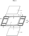
Fig. 3 is an exploded perspective view of the fuel cell composite sheet according toEmbodiment 1. -
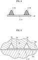
Fig. 4 is a sectional view taken along B-B line inFig. 1 . -
Fig. 5 is a sectional view showing a step of compression-molding gaskets. -
Fig. 6 is a perspective view showing a conventional fuel cell composite sheet. -
Fig. 7 is a sectional view showing a conventional molding die. -
Fig. 8 is a plan view showing a conventional lower die. -
Fig. 9 is a sectional view showing a molding die of Embodiment 2 (a section taken along IX-IX line inFig. 10 ). -
Fig. 10 is a plan view showing a lower die ofEmbodiment 2. -
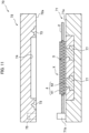
Fig. 11 is a sectional view showing a third step ofEmbodiment 2. - A fuel cell composite sheet and a method for manufacturing a fuel cell composite sheet according to embodiments will be described in detail with reference to the drawings. As shown in
Fig. 1 , a fuelcell composite sheet 1 includes aframe body 2, a membrane electrode assembly (MEA) 3, aholding member 4, andgaskets 5. A fuel cell is formed by holding the fuelcell composite sheet 1 with a pair of separators (not shown). This fuel cell is configured to generate electricity as being supplied with a hydrogen gas from the anode side and air (oxygen gas) from the cathode side. - In the fuel
cell composite sheet 1 and the method for manufacturing a fuel cell composite sheet according to the present embodiments, it is possible to prevent warpage by holding themembrane electrode assembly 3 by using theholding member 4. This makes it possible to improve handleability at the time of molding, assembling, and the like. Hereinafter, Embodiments will be described in detail. - The
frame body 2 is a film-shaped sheet having a rectangular shape in a plan view as shown inFig. 1 . Theframe body 2 is formed of, for example, a resin film such as a PEN (polyethylene terephthalate) film. The shape and material of theframe body 2 are only illustration, and theframe body 2 may be, for example, a metal separator, a carbon separator, or a sub-gasket with a gas diffusion layer, or the like. Theframe body 2 includes aframe body 21 and a plurality of through-holes 22 disposed on both sides of theframe body 21. A center portion of theframe body 21 is a portion where themembrane electrode assembly 3 is placed. The shapes, the positions, and the number of the through-holes 22 may be set as appropriate. - As shown in
Fig. 2 , the membrane electrode assembly (MEA) 3 includes apolymer electrolyte membrane 31 and gas diffusion layers 32, 32. The gas diffusion layers 32, 32 hold thepolymer electrolyte membrane 31 from the front surface side and the back surface side. Theframe body 21 extends from an outer edge of thepolymer electrolyte membrane 31 sideward. - As shown in
Fig. 2 andFig. 3 , the holdingmember 4 is a sheet-like member that holds themembrane electrode assembly 3 from the front surface side and the back surface side. In the present Embodiment, the holdingmember 4 includes amagnetic sheet 41 and ametal plate 42. Themagnetic sheet 41 has a rectangular shape and is arranged to cover the entire front side of themembrane electrode assembly 3. Themagnetic sheet 41 is laminated with, for example, a thermoplastic resin film. - The
metal plate 42 has a rectangular shape and is arranged to cover the entire back side of themembrane electrode assembly 3. In the present Embodiment, themetal plate 42 is formed of a material having a magnetic property (for example, SUS430). In this way, themagnetic sheet 41 and themetal plate 42 are attracted and attached by magnetic force. - Although the holding
member 4 is configured as described above in the present Embodiment, the holdingmember 4 may have another configuration as long as the holdingmember 4 is a sheet-like member that is harder than themembrane electrode assembly 3 and has a lower swelling rate than themembrane electrode assembly 3. - As shown in
Fig. 1 andFig. 4 , thegaskets 5 are sealing members formed of an elastic material. Thegaskets 5 and a separator (not shown) abut onto each other, so that a sealing region can be formed. In the present Embodiment, thegaskets 5 use silicone rubber (VMQ). Note that thegaskets 5 only have to be formed of a material having elasticity, and for example, ethylene-propylene-diene rubber (EPDM), fluororubber (FKM), polyisobutylene (PIB), a resin, or the like that has a rubber hardness Hs of 45 to 55 may be used. - The
gaskets 5 include afirst gasket 5A and a plurality ofsecond gaskets 5B. Thefirst gasket 5A is formed endlessly along an outer peripheral edge of theframe body 21. Thesecond gaskets 5B are formed endlessly along outer peripheral edges of the respective through-holes 22 inward of thefirst gasket 5A. Thesecond gaskets 5B are formed to correspond to the respective through-holes 22. Thegaskets 5 may be molded integrally on theframe body 21 by compression molding, or thegaskets 5 molded in advance may be bonded to theframe body 21 with an adhesive. - Next, the method for manufacturing a fuel cell composite sheet of the present Embodiment will be described. In the method for manufacturing a fuel cell composite sheet of the present Embodiment, a first step, a second step, and a third step are conducted.
- The first step is a step of disposing, in the
frame body 2, themembrane electrode assembly 3 including thegas diffusion layer 32. In the present Embodiment, themembrane electrode assembly 3 is bonded to and integrally molded on the center portion of theframe body 2. - The second step is a step of holding the
membrane electrode assembly 3 by using the holdingmember 4. In the present Embodiment, themembrane electrode assembly 3 is held by disposing themagnetic sheet 41 on the front surface (upper surface) of themembrane electrode assembly 3 and disposing themetal plate 42 on the back surface (lower surface) of themembrane electrode assembly 3. - The third step is a step of forming the
gaskets 5. In the present Embodiment, thegaskets 5 are integrally molded by compression molding. As shown inFig. 5 , in the third step, a first molding die 51 and a second molding die 52 are used. The first molding die 51 is aflat end surface 51a. The second molding die 52 includes aflat end surface 52a,recess portions surface 54. The abuttingsurface 54 is a surface that comes into contact with theframe body 2 at the time of molding. - In the third step, the
frame body 2 is held by theend surface 51a of the first molding die 51 and theend surface 52a and the abuttingsurface 54 of the second molding die 52. In this way, cavities surrounded by therecess portions frame body 2 are formed. By pouring a material into the cavities, followed by heating and pressurizing for a predetermined time, thegaskets 5 are formed integrally on theframe body 2. The fuel cellcomposite sheet 1 is formed by the above-described steps. - Here,
Fig. 6 is a perspective view showing a conventional fuel cellcomposite sheet 1A. The conventional fuel cellcomposite sheet 1A includes a film-shapedframe body 2A, amembrane electrode assembly 3A, andgaskets 5C. Thegaskets 5C are disposed around through-holes 22A as well. Since theframe body 2A is formed of a film, the conventional fuel cellcomposite sheet 1A is easily bent. For this reason, there is a problem that the conventional fuel cellcomposite sheet 1A is difficult to handle at the time of transporting, molding, assembling, and the like. In addition, there is a problem that since the conventional fuel cellcomposite sheet 1A warps due to a change in humidity at the time of compression molding and causes biting into a molding die and displacement of thegaskets 5C. - In this regard, according to the present Embodiment, it is possible to prevent warpage by holding the
membrane electrode assembly 3 by using the holdingmember 4. This makes it possible to improve handleability at the time of transporting, molding, assembling, and the like. - In addition, since warpage of the
membrane electrode assembly 3 can be prevented even in environments where humidity management is difficult like that of compression molding, it is possible to prevent binging into a molding die or displacement of thegaskets 5. - In addition, it is preferable that the holding
member 4 be a magnetic body like the present Embodiment. More specifically, it is preferable that the magnetic body include: themagnetic sheet 41; and themetal plate 42 having a magnetic property. If the holdingmember 4 were formed of a pair of plate-shaped members having no magnetic property, warpage and deformation would occur in the course of being inserted at the time of compression-molding thegaskets 5. However, since theframe body 2 and themembrane electrode assembly 3 are held while themagnetic sheet 41 and themetal plate 42 are attracted and attached by magnetic force by forming the holdingmember 4 of the present Embodiment with a magnetic body, it is possible to prevent theframe body 2 and themembrane electrode assembly 3 from deforming at the time of compression-molding thegaskets 5. - In addition, it is preferable that the
magnetic sheet 41 be laminated with a resin. This makes it possible to prevent outgas from being generated from themagnetic sheet 41 due to heat at the time of compression-molding thegaskets 5. - Next, a method for manufacturing a fuel cell composite sheet according to
Embodiment 2 will be described. First, problems in the case of using a conventional molding die will be described.Fig. 7 is a sectional view showing a conventional molding die.Fig. 8 is a plan view showing a conventional lower die. - As shown in
Fig. 7 andFig. 8 , a conventional molding die 60 includes a first molding die (lower die) 61 and a second molding die (upper die) 62. The first molding die 61 haspositioning portions flat end surface 61a. The positioningportions - The second molding die 62 has
recess portions 63, a firsthousing recess portion 64, and a secondhousing recess portion 65 in aflat end surface 62a. Therecess portions 63 are spaces in which to moldgaskets 6. The firsthousing recess portion 64 is a space in which to house amembrane electrode assembly 3 at the time of molding. The secondhousing recess portion 65 is a space in which to house thepositioning portion 61b at the time of molding. The molding die 60 is configured to compression-mold thegaskets 6 by pouring a material into therecess portions 63 while holding theframe body 2 with the first molding die 61 and the second molding die 62. As shown inFig. 8 , at the time of molding, theframe body 2 can be positioned relative to the first molding die 61 by causing theframe body 2 to abut on thepositioning portions - However, in the case of molding the
gaskets 6 by directly conducting compression-molding thegaskets 6 on theframe body 2 like the conventional molding die 60, there is a problem that the positions of theframe body 2 and the molding die 60 displace due to an impact of an operation such as sliding or clamping of the molding die 60 (see open arrows inFig. 8 ). It has conventionally been a general practice to make the positioning by using thepositioning portions Fig. 7 . In view of this, the second Embodiment aims at preventing displacements of theframe body 2 and the like. -
Fig. 9 is a sectional view showing a molding die ofEmbodiment 2.Fig. 10 is a plan view showing a lower die ofEmbodiment 2. As shown inFig. 9 andFig. 10 , the molding die 70 according toEmbodiment 2 includes a first molding die (lower die) 71 and a second molding die (upper die) 72. The first molding die 71 haspositioning portions end surface 71a, which serves as a molding surface. As shown inFig. 10 , the positioningportions molding die 77 are disposed. The magnetic members for amolding die 77 are, for example, magnets. The magnetic members for amolding die 77 are flush with theend surface 71a or disposed inside theend surface 71a. - The second molding die (upper die) 72 is movable relative to the first molding die 71. In an
end surface 72a, which serves as a molding surface, of the second molding die 72,recess portions 73, a firsthousing recess portion 74, and a secondhousing recess portion 75 are formed. Therecess portions 73 are spaces in which to mold gaskets. The firsthousing recess portion 74 is a space in which to house themembrane electrode assembly 3 at the time of molding. The secondhousing recess portions 75 are spaces which are disposed at positions corresponding to thepositioning portions 61b, and in which to house thepositioning portion 61b at the time of molding. In addition, although specific illustration is omitted, in the second molding die 72, a second housing recess portion in which to house thepositioning portion 71c is also disposed. The molding die 70 is configured to compression-mold the gaskets by pouring a material into therecess portions 73 while holding theframe body 2 with the first molding die 71 and the second molding die 72. - Next, the method for manufacturing a fuel cell composite sheet of the present Embodiment will be described. In the method for manufacturing a fuel cell composite sheet of the present Embodiment, a first step, a second step, and a third step are conducted. The first step and the second step are the same as those of
Embodiment 1. In the second step, themagnetic sheet 41 and themetal plate 42 as the holdingmember 4 are disposed on both surfaces of a sub-gasket with MEA.GDL (gas diffusion layer). Note that this molded article is referred to as an "intermediate body X". - The third step is a step of forming gaskets. In the present Embodiment, the gaskets are integrally molded by compression molding. As shown in
Fig. 11 , in the third step, the intermediate body X is disposed on theend surface 71a of the first molding die 71. - Since the holding
member 4 is formed of themagnetic sheet 41 and themetal plate 42, once the intermediate body X is disposed on the first molding die 71, the intermediate body X is secured to be immovable by the magnetic force of the magnetic member for amolding die 77. Next, the first molding die 71 and the second molding die 72 are brought closer to each other to hold theframe body 2 between the end surfaces 71a, 72a. In this way, cavities are formed by theframe body 2 and therecess portions 73. By pouring a material into the cavities, followed by heating and pressurizing for a predetermined time, the gaskets are formed integrally on theframe body 2. - According to the method for manufacturing a fuel cell composite sheet according to
Embodiment 2 described above, since the first molding die 71 includes the magnetic member for amolding die 77, it is possible to prevent displacement of the intermediate body X due to an impact at the time of molding with the molding die 70 by means of the magnetic force. In addition, after releasing the die, the product remains as it is in one of the molding dies (first molding die 71). This eliminates a work of removing the product from the second molding die 72 unlike the conventional techniques, and thus making it possible to improve the molding cycle time. In addition, at the time of releasing the die after molding, it is possible to prevent the product from remaining in the second molding die 72 (another of the molding dies) and the product from falling down. - Although Embodiments have been described above, changes in design are possible as appropriate.
-
- 1
- fuel cell composite sheet
- 2
- frame body
- 3
- membrane electrode assembly
- 4
- holding member
- 5
- gasket
- 21
- frame body
- 22
- through-hole
- 31
- polymer electrolyte membrane
- 32
- gas diffusion layer
- 41
- magnetic sheet
- 42
- metal plate
- 70
- molding die
- 71
- first molding die (lower die)
- 72
- second molding die (upper die)
- 77
- magnetic member for a molding die
Claims (9)
- A fuel cell composite sheet comprising:a frame body;a membrane electrode assembly which is disposed in the frame body and which includes a gas diffusion layer; anda holding member as a sheet, the holding member being harder than the frame body and holding the membrane electrode assembly.
- The fuel cell composite sheet according to claim 1 further comprising:
a gasket disposed on the frame body. - The fuel cell composite sheet according to claim 1 or 2, wherein the holding member is a magnetic body.
- The fuel cell composite sheet according to claim 3, wherein the magnetic body includes: a magnetic sheet; and a metal plate having a magnetic property.
- The fuel cell composite sheet according to claim 4, wherein the magnetic sheet is laminated with a resin.
- A method for manufacturing a fuel cell composite sheet, the method comprising:disposing in a frame body a membrane electrode assembly including a gas diffusion layer; andholding the membrane electrode assembly by using a holding member as a sheet, the holding member being harder than the frame body.
- The method for manufacturing a fuel cell composite sheet according to claim 6, the method further comprising:
forming a gasket on the frame body by compression molding. - The method for manufacturing a fuel cell composite sheet according to claim 7, wherein the holding member includes: a magnetic body,wherein one of a pair of molding dies includes a magnetic member for a molding die, andwherein the compression molding is conducted while the frame body, the membrane electrode assembly, and the holding member are secured to the one of the pair of molding dies under magnetic force.
- The method for manufacturing a fuel cell composite sheet according to claim 8, wherein
the magnetic body includes: a magnetic sheet; and a metal plate having a magnetic property.
Applications Claiming Priority (2)
| Application Number | Priority Date | Filing Date | Title |
|---|---|---|---|
| JP2021114120 | 2021-07-09 | ||
| PCT/JP2022/022671 WO2023281953A1 (en) | 2021-07-09 | 2022-06-03 | Fuel cell composite sheet and fuel cell composite sheet production method |
Publications (2)
| Publication Number | Publication Date |
|---|---|
| EP4369445A1 true EP4369445A1 (en) | 2024-05-15 |
| EP4369445A4 EP4369445A4 (en) | 2025-10-01 |
Family
ID=84800552
Family Applications (1)
| Application Number | Title | Priority Date | Filing Date |
|---|---|---|---|
| EP22837372.6A Pending EP4369445A4 (en) | 2021-07-09 | 2022-06-03 | FUEL CELL COMPOSITE FILM AND FUEL CELL COMPOSITE FILM PRODUCTION PROCESS |
Country Status (5)
| Country | Link |
|---|---|
| US (1) | US20240405232A1 (en) |
| EP (1) | EP4369445A4 (en) |
| JP (1) | JP7450067B2 (en) |
| CN (1) | CN116529915A (en) |
| WO (1) | WO2023281953A1 (en) |
Family Cites Families (11)
| Publication number | Priority date | Publication date | Assignee | Title |
|---|---|---|---|---|
| US20050281981A1 (en) * | 2002-08-30 | 2005-12-22 | Raymond Puffer | Fixtures and methods for facilitating the fabrication of devices having thin film materials |
| JP2006331861A (en) * | 2005-05-26 | 2006-12-07 | Nitto Denko Corp | Fuel cell manufacturing method and fuel cell manufacturing equipment |
| KR101270856B1 (en) * | 2005-04-01 | 2013-06-05 | 파나소닉 주식회사 | Mea, mea manufacturing method, and high polymer electrolyte fuel cell |
| JP4096027B2 (en) * | 2006-06-26 | 2008-06-04 | 松下電器産業株式会社 | Solid polymer electrolyte fuel cell |
| JP4719771B2 (en) * | 2007-06-11 | 2011-07-06 | パナソニック株式会社 | Electrode-membrane-frame assembly for fuel cell and manufacturing method thereof, and polymer electrolyte fuel cell and manufacturing method thereof |
| JP2015018662A (en) * | 2013-07-10 | 2015-01-29 | 日産自動車株式会社 | Unit cell structure, manufacturing method for unit cell and unit cell manufactured by that manufacturing method |
| JP6383200B2 (en) | 2014-07-10 | 2018-08-29 | Nok株式会社 | Manufacturing method of plate-integrated gasket |
| US10847826B2 (en) * | 2017-02-16 | 2020-11-24 | Panasonic Intelletual Property Management Co., Ltd. | Polymer electrolyte fuel cells and production method thereof |
| DE102017215507A1 (en) * | 2017-09-05 | 2019-03-07 | Volkswagen Ag | A process for producing a composite of a bipolar plate and a membrane-electrode assembly and composite produced according to the method |
| CN109847974B (en) * | 2018-11-23 | 2021-07-09 | 一汽解放汽车有限公司 | A proton exchange membrane fuel cell membrane electrode spraying fixture and a method for preparing a membrane electrode using the same |
| CN211829054U (en) * | 2020-05-11 | 2020-10-30 | 苏州朗泰新能源科技有限公司 | Novel clamp for preparing fuel cell membrane electrode |
-
2022
- 2022-06-03 JP JP2022567550A patent/JP7450067B2/en active Active
- 2022-06-03 EP EP22837372.6A patent/EP4369445A4/en active Pending
- 2022-06-03 US US18/577,492 patent/US20240405232A1/en active Pending
- 2022-06-03 CN CN202280007108.6A patent/CN116529915A/en active Pending
- 2022-06-03 WO PCT/JP2022/022671 patent/WO2023281953A1/en not_active Ceased
Also Published As
| Publication number | Publication date |
|---|---|
| JPWO2023281953A1 (en) | 2023-01-12 |
| EP4369445A4 (en) | 2025-10-01 |
| WO2023281953A1 (en) | 2023-01-12 |
| US20240405232A1 (en) | 2024-12-05 |
| CN116529915A (en) | 2023-08-01 |
| JP7450067B2 (en) | 2024-03-14 |
Similar Documents
| Publication | Publication Date | Title |
|---|---|---|
| CN101523647B (en) | Membrane electrode assembly, method for producing the same, and solid polymer fuel cell using the same | |
| JP3542550B2 (en) | Method of forming fuel cell seal | |
| CN102484264B (en) | Fuel cell | |
| EP2466674B1 (en) | Method for manufacturing reinforced membrane electrode assembly | |
| CN102197527B (en) | Fuel Cell Sealing Structure | |
| CN102468496A (en) | Metallic porous body for fuel cell | |
| CN101356675A (en) | solid polymer electrolyte fuel cell | |
| US9196911B2 (en) | Fuel cell gas diffusion layer integrated gasket | |
| JP6674018B2 (en) | Gasket mounting method | |
| CN111313051A (en) | Elastic cell frame for fuel cell, method of manufacturing the same, and unit cell using the same | |
| JP5142080B2 (en) | Method for manufacturing seal structure | |
| CN102468456B (en) | There is the fuel cell separator plate of liner and the method for manufacturing it | |
| US20030127806A1 (en) | Alignment feature for a fuel cell seal | |
| JP6151065B2 (en) | Manufacturing method of plate-integrated gasket | |
| US20240405232A1 (en) | Fuel cell composite sheet and fuel cell composite sheet production method | |
| JP3724797B2 (en) | Fuel cell separator with seal and membrane electrode assembly with seal | |
| KR101822246B1 (en) | Fuel cell stack | |
| JP2022165441A (en) | fuel cell stack | |
| JP2021143676A (en) | Manufacturing method of gasket | |
| KR101762375B1 (en) | Gasket for fuel cell | |
| KR100763590B1 (en) | Sealing structure of fuel cell, fuel cell including same and manufacturing method thereof | |
| JP2015146230A (en) | Fuel cell | |
| KR20120056022A (en) | Gasket Structure for Fuel Cell | |
| KR200470519Y1 (en) | Gasket united separate plate construction of fuel battery | |
| JP5809614B2 (en) | Fuel cell stack |
Legal Events
| Date | Code | Title | Description |
|---|---|---|---|
| STAA | Information on the status of an ep patent application or granted ep patent |
Free format text: STATUS: THE INTERNATIONAL PUBLICATION HAS BEEN MADE |
|
| PUAI | Public reference made under article 153(3) epc to a published international application that has entered the european phase |
Free format text: ORIGINAL CODE: 0009012 |
|
| STAA | Information on the status of an ep patent application or granted ep patent |
Free format text: STATUS: REQUEST FOR EXAMINATION WAS MADE |
|
| 17P | Request for examination filed |
Effective date: 20240109 |
|
| AK | Designated contracting states |
Kind code of ref document: A1 Designated state(s): AL AT BE BG CH CY CZ DE DK EE ES FI FR GB GR HR HU IE IS IT LI LT LU LV MC MK MT NL NO PL PT RO RS SE SI SK SM TR |
|
| DAV | Request for validation of the european patent (deleted) | ||
| DAX | Request for extension of the european patent (deleted) | ||
| A4 | Supplementary search report drawn up and despatched |
Effective date: 20250901 |
|
| RIC1 | Information provided on ipc code assigned before grant |
Ipc: H01M 8/1004 20160101AFI20250826BHEP Ipc: H01M 8/0273 20160101ALI20250826BHEP Ipc: H01M 8/0286 20160101ALI20250826BHEP Ipc: H01M 8/10 20160101ALI20250826BHEP |