EP4368942B1 - Underwater mounting positioning method for final joint in immersed tube tunnel - Google Patents
Underwater mounting positioning method for final joint in immersed tube tunnel Download PDFInfo
- Publication number
- EP4368942B1 EP4368942B1 EP23842470.9A EP23842470A EP4368942B1 EP 4368942 B1 EP4368942 B1 EP 4368942B1 EP 23842470 A EP23842470 A EP 23842470A EP 4368942 B1 EP4368942 B1 EP 4368942B1
- Authority
- EP
- European Patent Office
- Prior art keywords
- coordinate system
- displacement meter
- cable
- closure joint
- camera
- Prior art date
- Legal status (The legal status is an assumption and is not a legal conclusion. Google has not performed a legal analysis and makes no representation as to the accuracy of the status listed.)
- Active
Links
Images




Classifications
-
- E—FIXED CONSTRUCTIONS
- E02—HYDRAULIC ENGINEERING; FOUNDATIONS; SOIL SHIFTING
- E02D—FOUNDATIONS; EXCAVATIONS; EMBANKMENTS; UNDERGROUND OR UNDERWATER STRUCTURES
- E02D29/00—Independent underground or underwater structures; Retaining walls
- E02D29/063—Tunnels submerged into, or built in, open water
- E02D29/073—Tunnels or shuttering therefor assembled from sections individually sunk onto, or laid on, the water-bed, e.g. in a preformed trench
-
- G—PHYSICS
- G01—MEASURING; TESTING
- G01B—MEASURING LENGTH, THICKNESS OR SIMILAR LINEAR DIMENSIONS; MEASURING ANGLES; MEASURING AREAS; MEASURING IRREGULARITIES OF SURFACES OR CONTOURS
- G01B11/00—Measuring arrangements characterised by the use of optical techniques
- G01B11/002—Measuring arrangements characterised by the use of optical techniques for measuring two or more coordinates
-
- E—FIXED CONSTRUCTIONS
- E02—HYDRAULIC ENGINEERING; FOUNDATIONS; SOIL SHIFTING
- E02D—FOUNDATIONS; EXCAVATIONS; EMBANKMENTS; UNDERGROUND OR UNDERWATER STRUCTURES
- E02D15/00—Handling building or like materials for hydraulic engineering or foundations
- E02D15/08—Sinking workpieces into water or soil inasmuch as not provided for elsewhere
Definitions
- the present application relates to the technical field of immersed tunnel construction, and in particular to an underwater installation positioning method for a closure joint of an immersed tunnel.
- the closure joint is usually disposed inside the last tube coupling, and when the last tube coupling is immersed and installed, the closure joint is pushed outwards to be butted with the to-be-butted tube coupling, so as to achieve through connection of the immersed tunnel; it can be understood that when the closure joint is pushed outwards, a plane displacement and plane rotation will occur under the constraint of the last tube coupling, but tilt or pitch will not occur; therefore, it is necessary to monitor the plane displacement and the rotation angle of the closure joint in real time during a pushing process of the closure joint to obtain real-time posture information of the closure joint, so as to ensure the installation accuracy of the closure joint to meet construction requirements.
- the commonly used positioning methods for closure joint installation comprise a measuring tower method, a sonar method, etc.
- the positioning accuracy of these conventional underwater positioning methods gradually decreases, and the cost is high, thus it is difficult to better ensure the accuracy and reliability of installing construction of the closure joint.
- CN216815272U discloses an underwater installation positioning system for the final joint of an immersed tube tunnel, and the system comprises a cable displacement meter, a camera displacement meter, a serial port server and a data processing terminal.
- the present application provides an underwater installation positioning method for a closure joint of an immersed tunnel, aiming at accurately monitoring a plane displacement and a rotation angle during the pushing process of the closure joint, achieving high-accuracy positioning and posture determination of the closure joint, and better ensuring the accuracy and reliability of the installing construction of the closure joint.
- the plane displacement and the rotation angle of the closure joint can be accurately monitored in the pushing process of the closure joint, so as to achieve the high-accuracy positioning and posture determination of the closure joint and better ensure the accuracy and reliability of the installation and construction of the closure joint.
- first and second are for descriptive purposes only, and cannot be understood as indicating or implying the relative importance or implicitly indicating the number of indicated technical features. Therefore, features defined as “first” and “second” may explicitly or implicitly include one or more of the features.
- connection may be fixed connection or detachable connection or connection in an integral whole, may be direct connection or indirect connection through an intermediate medium, and may be inter communication between two elements, unless it may be clearly defined and limited otherwise.
- connection may be fixed connection or detachable connection or connection in an integral whole, may be direct connection or indirect connection through an intermediate medium, and may be inter communication between two elements, unless it may be clearly defined and limited otherwise.
- connection may be fixed connection or detachable connection or connection in an integral whole, may be direct connection or indirect connection through an intermediate medium, and may be inter communication between two elements, unless it may be clearly defined and limited otherwise.
- connection may be fixed connection or detachable connection or connection in an integral whole, may be direct connection or indirect connection through an intermediate medium, and may be inter communication between two elements, unless it may be clearly defined and limited otherwise.
- connection may be fixed connection or detachable connection or connection in an integral whole, may be direct connection or indirect connection through an intermediate medium, and may be inter communication between two elements, unless it may be clearly defined
- a closure joint 30 of an immersed tunnel is disposed inside a last tube coupling 40; after the last tube coupling 40 is immersed and installed, the closure joint 30 is pushed outwards to butt with a to-be-butted tube coupling 50, so as to achieve through connection of the immersed tunnel.
- Embodiments of an underwater installation positioning system for a closure joint of an immersed tunnel described below are not encompassed by the wording of the claims but are considered as useful for understanding the invention.
- an embodiment of an underwater installation positioning system for a closure joint of an immersed tunnel comprising: at least two underwater positioning apparatuses 10, at least two underwater positioning objects 20, a serial port server 60 and a data processing terminal 70; it should be noted that a number of the underwater positioning apparatuses 10 is consistent with a number of the underwater positioning objects 20.
- the underwater positioning apparatuses 10 are arranged at one end of the closure joint 30 close to the to-be-butted tube coupling 50.
- Each underwater positioning apparatus 10 comprises an instrument box 11, and a camera displacement meter 12 and a cable displacement meter 13 that are installed in the instrument box 11.
- a shooting direction of the camera displacement meter 12 and an outgoing direction of the cable displacement meter 13 both face the to-be-butted tube coupling 50.
- the underwater positioning objects 20 are arranged at one end of the to-be-butted tube coupling 50 close to the closure joint 30, and are arranged opposite to the underwater positioning apparatuses 10 one by one.
- both the camera displacement meter 12 and the cable displacement meter 13 measure a distance and a direction with respect to the corresponding underwater positioning object 20, so as to position and determine a posture of the closure joint 30.
- Each underwater positioning object 20 is provided with a cable measuring point 201 and a light source measuring point 202, wherein the cable measuring point 201 is used for measuring in cooperation with the cable displacement meter 13, and the light source measuring point 202 is used for measuring in cooperation with the camera displacement meter 12.
- the compact and integrated arrangement of various positioning devices is implemented, so that the underwater positioning apparatus 10 has good apparatus redundancy, the installation difficulty and space occupation of various positioning devices are significantly reduced, the construction efficiency is improved, the integrated arrangement of communication cables of the various positioning devices can be implemented, and the construction cost is reduced; moreover, the various positioning devices can be calibrated uniformly to improve the calibration accuracy of the underwater positioning apparatus 10, and redundant measurement data of different positioning devices can be mutually checked to improve the positioning accuracy, so as to achieve high-accuracy positioning and posture determination of the closure joint 30.
- the serial port server 60 is in communication connection with both the camera displacement meter 12 and the cable displacement meter 13 to receive and transmit measurement data of the camera displacement meter 12 and the cable displacement meter 13 in real time.
- the data processing terminal 70 is in communication connection with the serial port server 60 and is used for acquiring the measurement data of the camera displacement meter 12 and the cable displacement meter 13 to calculate a real-time plane displacement and a real-time rotation angle of the closure joint 30, so that real-time position and posture information in a pushing process of the closure joint 30 can be accurately obtained, and the installation accuracy of the closure joint 30 can be ensured to meet construction requirements.
- the underwater positioning apparatuses 10 each comprising the camera displacement meter 12 and the cable displacement meter 13
- the plane displacement and the rotation angle of the closure joint 30 can be precisely monitored in the pushing process of the closure joint 30, so as to achieve the high-accuracy positioning and posture determination of the closure joint 30 and better ensure the accuracy and reliability of the installing construction of the closure joint 30.
- the camera displacement meter 12 comprises two cameras 121 disposed side by side to measure a distance and direction between the camera displacement meter 12 and the light source measuring point 202, that is, to determine a relative position relationship between the closure joint 30 and the to-be-butted tube coupling 50 by a camera measuring method.
- the shooting directions of the two cameras 121 face the light source measuring point 202, and the two cameras 121 form a binocular camera, which is more conducive to the measurement and positioning of the light source measuring point 202.
- the cable displacement meter 13 comprises a rotatable pull rod 131, a retractable cable 132 penetrating through the pull rod 131, a cable encoder 134 for measuring a length of the cable 132, and a laser angle measuring device 133 for measuring a direction of the cable 132, so as to measure the distance and direction between the cable displacement meter 13 and the cable measuring point 201, that is, to determine the relative position relationship between the closure joint 30 and the to-be-butted tube coupling 50 by a cable measuring method.
- a rotation center of the pull rod 131 is located in the instrument box 11, and a rotation state of the cable 132 is consistent with that of the pull rod 131.
- a rear end of the pull rod 131 is rotatably connected to an interior of the instrument box 11 through a universal joint 135, and a front end of the pull rod 131 is connected to the cable measuring point 201 through the cable 132, and the pull rod 131 rotates around the rear end of the pull rod 131 due to the movement of the cable measuring point 201.
- one end of the cable 132 is wound around a winding reel 136, and the other end of the cable is to be connected with the cable measuring point 201; the winding reel 136 is used for winding and unwinding the cable 132, and the cable encoder 134 is disposed at the winding reel 136 to measure a rotation angle of the winding reel 136, and then calculate the length of the cable 132.
- the laser angle measuring device 133 comprises a laser 1331 and a light spot camera 1332; the laser 1331 is installed on the pull rod 131 to rotate synchronously with the pull rod 131, and the laser 1331 is used for emitting laser light outwards; the light spot camera 1332 faces the laser 1331, so that the laser light emitted by the laser 1331 can be projected on the light spot camera 1332 to form a light spot; and the light spot camera 1332 is used for measuring position information of the light spot, thereby calculating a direction of the pull rod 131, that is, the direction of the cable 132, the direction of the pull rod 131 comprises a horizontal angle and a vertical angle.
- a change of the rotation angle of the laser 1331 can be calculated; since the laser 1331 rotates synchronously with the pull rod 131, the change of the rotation angle of the laser 1331 is the change of the rotation angle of the pull rod 131.
- the pull rod 131 is straightened first, that is, to make the horizontal angle and the vertical angle of the pull rod 131 both zero, and a position of the light spot at this moment is calibrated as an initial position; when the pull rod 131 and the laser 1331 rotate synchronously, a real-time position of the light spot changes accordingly; according to a relationship between the real-time position of the light spot and the initial position, the rotation angle of the laser 1331 can be calculated, the rotation angle of the laser 1331 comprises a horizontal rotation angle and a vertical rotation angle; since the horizontal angle and the vertical angle of the pull rod 131 are both zero when calibrating, the horizontal rotation angle of the laser 1331 is equal to the horizontal angle of the pull rod 131, and the vertical rotation angle of the laser 1331 is equal to the vertical angle of the pull rod 131, thereby obtaining the direction of the pull rod 131.
- the various positioning devices more redundant measurement data
- the serial port server 60 is installed inside the instrument box 11; the serial port server 60 is in communication connection with the cable encoder 134, the laser angle measuring device 133 and the camera 121, so as to output the measurement data of the cable encoder 134, the laser angle measuring device 133 and the camera 121.
- each underwater positioning object 20 comprises a main casing 21, a pull ring 23 installed on an outer side of the main casing 21, and a plurality of light sources 22 installed in the main casing 21; a hooking direction of the pull ring 23 faces the corresponding underwater positioning apparatus 10; and light-emitting directions of the plurality of light sources 22 also face the corresponding underwater positioning apparatus 10.
- the pull ring 23 is used to be connected with the cable displacement meter 13 as the cable measuring point 201 for the cable displacement meter 13.
- the plurality of light sources 22 constitute light source measuring points 202 for the camera displacement meter 12, and provide a field-of-view for camera measuring of the camera displacement meter 12.
- each underwater positioning object 20 further comprises a back plate 24, the back plate 24 is opposite to the main casing 21 in parallel, and a plurality of lamp cabins 25 are disposed between the back plate 24 and the main casing 21, and each lamp cabin 25 is hermetically connected with the back plate 24 and the main casing 21.
- a Lamp bead is installed in each lamp cabin 25, light-transmitting ports 26 corresponding to lamp beads one by one are formed in the main casing 21, filter plates are installed at the light-transmitting ports 26, and the lamp beads provide light sources 22 for the underwater positioning object; it can be understood that the filter plates are hermetically connected with the main casing 21 to ensure the tightness of the lamp cabins 25.
- Each lamp bead emits laser light towards its corresponding light-transmitting port 26 and transmits the laser light outward through the filter plate.
- the underwater positioning object 20 may be used as the light source measuring point 202 to meet the camera measurement requirements of the camera displacement meter 12.
- the pull ring 23 is convexly disposed on a surface of the main casing 21 facing away from the back plate 24, and the pull ring 23 is to be connected with the cable 132 of the cable displacement meter 13; through the arrangement of the pull ring 23, the underwater positioning object 20 can be used as the cable measuring point 201 to meet cable measurement requirements of the cable displacement meter 13.
- an embodiment of the present application provides an underwater installation positioning method for a closure joint of an immersed tunnel, which is performed by using the underwater installation positioning system for the closure joint of the immersed tunnel according to any embodiment as described above.
- the method comprises the following steps: S1: a step of construction calibrating, specifically comprising:
- the plane displacement and the rotation angle of the closure joint 30 can be accurately monitored, so as to achieve high-accuracy positioning and posture determination of the closure joint 30 and ensure the accuracy and reliability of pushing installation of the closure joint 30.
- a specific method of the through measurement in step S22 is the prior art, which can be reasonably realized by those skilled in the art based on the prior art, and will not be described in detail in the present application.
- Step S3 comprises the following steps:
- the calculation of the real-time plane displacement and the real-time rotation angle in the pushing process of the closure joint 30 is realized, so that the plane displacement and the rotation angle of the closure joint 30 can be monitored in real time, and real-time posture information of the closure joint 30 can be accurately obtained.
- step S3 further comprises: S33: substituting the result of X into the formula (1) to obtain the measurement correction number V ki ; judging whether an absolute value of V ki exceeds a preset maximum allowable deviation; if the absolute value does not exceed the preset maximum allowable deviation, calculation accuracy check of X at a current pushing position is completed, that is, the calculation result of a current posture of the closure joint 30 is determined to be accurate, and performing the next pushing according to step S3 until the pushing of the closure joint 30 is completed; if the absolute value exceeds the preset maximum allowable deviation, eliminating coordinate data of a measuring point corresponding to this V ki , and using coordinate data of other measuring points that have not been eliminated to calculate X again; if the amount of the coordinate data of the measuring points that have not been eliminated is less than 2, re-measuring and re-acquiring the plane coordinates of the cable measuring points 201 and the light source measuring points 202 in the closure joint coordinate system at the current pushing position, so as to re-calculate and
- the underwater installation positioning method for the closure joint of the immersed tunnel further comprises the following steps: S0: a step of apparatus calibrating, which is performed before the underwater positioning apparatuses 10 are installed at the closure joint 30, calibrating a transformation parameter X gy between the cable displacement meter coordinate system and an instrument box coordinate system, and calibrating a transformation parameter X fy between the camera displacement meter coordinate system and the instrument box coordinate system; specifically, as shown in Fig. 9 , the step of apparatus calibrating comprises:
- various positioning devices can be calibrated uniformly in a same coordinate system, so that the calibration of the underwater positioning apparatus 10 itself is implemented and the calibration accuracy is improved, and the measurement results of the cable displacement meter 13 and the camera displacement meter 12 are ensured to be more accurate and reliable, thereby achieving high-accuracy positioning and posture determination of the closure joint in pushing process of the closure joint.
- step S12 when the underwater positioning apparatuses 10 are installed on the closure joint 30, the transformation parameter X yj between the instrument box coordinate system and the closure joint coordinate system is calibrated first, then X gy and X yj are combined to obtain the transformation parameter X gj between the cable displacement meter coordinate system and the closure joint coordinate system, and X fy and X yj are combined to obtain the transformation parameter X fj between the camera displacement meter coordinate system and the closure joint coordinate system.
- the calculation of the transformation parameter between the cable displacement meter coordinate system and the closure joint coordinate system, and the calculation of the transformation parameter between the camera displacement meter coordinate system and the closure joint coordinate system are realized.
- the plane displacement and the rotation angle of the closure joint 30 can be accurately monitored in the pushing process of the closure joint 30, so as to achieve the high-accuracy positioning and posture determination of the closure joint 30 and better ensure the accuracy and reliability of the installing construction of the closure joint 30.
Landscapes
- Engineering & Computer Science (AREA)
- Physics & Mathematics (AREA)
- General Physics & Mathematics (AREA)
- Environmental & Geological Engineering (AREA)
- Life Sciences & Earth Sciences (AREA)
- General Life Sciences & Earth Sciences (AREA)
- Mining & Mineral Resources (AREA)
- Paleontology (AREA)
- Civil Engineering (AREA)
- General Engineering & Computer Science (AREA)
- Structural Engineering (AREA)
- Length Measuring Devices By Optical Means (AREA)
Description
- The present application claims the priority to
Chinese patent application No. 202310892430.8 Chinese patent application No. 202321922323.7 Chinese patent application No. 202321913304.8 Chinese application No. 202321912770.4 and entitled "Underwater Positioning Target", filed to the China Patent Office on July 20th, 2023 - The present application relates to the technical field of immersed tunnel construction, and in particular to an underwater installation positioning method for a closure joint of an immersed tunnel.
- During the construction of an immersed tunnel, in order to allow a last tube coupling to be immersed smoothly, a distance longer than the last tube coupling must be left; and when the last tube coupling is immersed and installed, the last tube coupling and a to-be-butted tube coupling are connected through a closure joint. The closure joint is usually disposed inside the last tube coupling, and when the last tube coupling is immersed and installed, the closure joint is pushed outwards to be butted with the to-be-butted tube coupling, so as to achieve through connection of the immersed tunnel; it can be understood that when the closure joint is pushed outwards, a plane displacement and plane rotation will occur under the constraint of the last tube coupling, but tilt or pitch will not occur; therefore, it is necessary to monitor the plane displacement and the rotation angle of the closure joint in real time during a pushing process of the closure joint to obtain real-time posture information of the closure joint, so as to ensure the installation accuracy of the closure joint to meet construction requirements.
- At present, the commonly used positioning methods for closure joint installation comprise a measuring tower method, a sonar method, etc. However, with the gradual increase of a working water depth, the positioning accuracy of these conventional underwater positioning methods gradually decreases, and the cost is high, thus it is difficult to better ensure the accuracy and reliability of installing construction of the closure joint.
-
CN216815272U discloses an underwater installation positioning system for the final joint of an immersed tube tunnel, and the system comprises a cable displacement meter, a camera displacement meter, a serial port server and a data processing terminal. - To overcome the shortcomings in related arts, the present application provides an underwater installation positioning method for a closure joint of an immersed tunnel, aiming at accurately monitoring a plane displacement and a rotation angle during the pushing process of the closure joint, achieving high-accuracy positioning and posture determination of the closure joint, and better ensuring the accuracy and reliability of the installing construction of the closure joint.
- The invention is set out in the appended set of claims.
- Based on the above technical solutions, according to the underwater installation positioning method for the closure joint of the immersed tunnel in the embodiments of the present application, the plane displacement and the rotation angle of the closure joint can be accurately monitored in the pushing process of the closure joint, so as to achieve the high-accuracy positioning and posture determination of the closure joint and better ensure the accuracy and reliability of the installation and construction of the closure joint.
- The accompanying drawings described herein are to provide a further understanding of the present application and constitute a part of the present application. The illustrative embodiments and their descriptions are provided to explain the present application and do not constitute undue limitations on the present application. In the drawings:
-
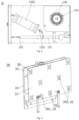
Fig. 1 is a first schematic structural diagram (perspective display) of an underwater positioning apparatus according to an embodiment of the present application; -
Fig. 2 is a second schematic structural diagram of the underwater positioning apparatus according to the embodiment of the present application; -
Fig. 3 is a top view of the underwater positioning apparatus according to the embodiment of the present application; -
Fig. 4 is a schematic diagram of an underwater positioning object according to the embodiment of the present application; -
Fig. 5 is a schematic diagram of communication connection according to the embodiment of the present application; -
Fig. 6 is a schematic diagram of an initial state of a closure joint coordinate system in an underwater installation positioning method for a closure joint of an immersed tunnel according to an embodiment of the present application; -
Fig. 7 is a schematic diagram of a state of the closure joint coordinate system in the underwater installation positioning method for the closure joint of the immersed tunnel during construction according to the embodiment of the present application; -
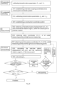
Fig. 8 is a flowchart of the underwater installation positioning method for the closure joint of the immersed tunnel according to the embodiment of the present application; -
Fig. 9 is a flowchart of steps in a step S0 of apparatus calibration of the underwater installation positioning method for the closure joint of the immersed tunnel according to the embodiment of the present application; -
Fig. 10 is a schematic diagram of a target point layout in the S0 apparatus calibration step of the underwater installation positioning method for the closure joint of the immersed tunnel according to the embodiment of the present application; -
Fig. 11 is a logical block diagram for calculating a transformation parameter Xgy of a cable displacement meter coordinate system and a transformation parameter Xfy of a camera displacement meter coordinate system in step S05 of the underwater installation positioning method for the closure joint of the immersed tunnel according to the embodiment of the present application; and -
Fig. 12 is a logical block diagram showing transformations of coordinate systems in step S12 of the underwater installation positioning method for the closure joint of the immersed tunnel according to the embodiment of the present application. - In the drawings:
- 10. underwater positioning apparatus; 11. instrument box; 111. laser pointer; 12. camera displacement meter; 121. camera; 13. cable displacement meter; 131. pull rod; 132. cable; 133. laser angle measuring device; 134. cable encoder; 1331. laser; 1332. light spot camera; 135. universal joint; 136. winding reel;
- 20. underwater positioning object; 201. cable measuring point; 202. light source measuring point; 21. main casing; 22. light source; 23. pull ring; 24. back plate; 25. lamp cabin; 26. light-transmitting port;
- 30. closure joint;
- 40. last tube coupling;
- 50. to-be-butted tube coupling;
- 60. serial port server; 70. data processing terminal.
- The technical solutions in the embodiments will be clearly and completely described below with reference to the drawings in the embodiments of the present application. Apparently, the described embodiments are merely some, but not all, of the embodiments of this application. Based on the embodiments of the present application, all other embodiments obtained by those of ordinary skill in the art without involving any inventive effort shall fall into the protection scope of the present application.
- It should be noted that, in the description of the present application, directional or positional relationships indicated by terms such as "center", "lateral", "longitudinal", "upper", "lower" , "top", "bottom" , "inner" , "outer" , "left" , "right" , "front" , "rear", "vertical", "horizontal" are based on directional or positional relationships as shown in the accompanying drawings, and are only for the purposes of facilitating and simplifying the descriptions, rather than indicating or implying that the referred apparatus or element has to have a specific direction or be constructed and operated in the specific direction, and therefore, they cannot be regarded as limitations on the present application.
- Terms "first" and "second" are for descriptive purposes only, and cannot be understood as indicating or implying the relative importance or implicitly indicating the number of indicated technical features. Therefore, features defined as "first" and "second" may explicitly or implicitly include one or more of the features.
- In the description of the present application, it needs to be noted that the terms "mounting", "connected" and "connection" should be understood in a broad sense, for example, "connection" may be fixed connection or detachable connection or connection in an integral whole, may be direct connection or indirect connection through an intermediate medium, and may be inter communication between two elements, unless it may be clearly defined and limited otherwise. For those skilled in the art, the specific meanings of the above terms in present application may be understood according to specific situations. The description of "a plurality of", "sets of" and the like in this application refers to two (sets) or more.
- Referring to
Fig. 6 and Fig. 7 , a closure joint 30 of an immersed tunnel is disposed inside alast tube coupling 40; after thelast tube coupling 40 is immersed and installed, the closure joint 30 is pushed outwards to butt with a to-be-butted tube coupling 50, so as to achieve through connection of the immersed tunnel. - Embodiments of an underwater installation positioning system for a closure joint of an immersed tunnel described below are not encompassed by the wording of the claims but are considered as useful for understanding the invention.
- As shown in
Figs. 1-5 , an embodiment of an underwater installation positioning system for a closure joint of an immersed tunnel, comprising: at least twounderwater positioning apparatuses 10, at least two underwater positioning objects 20, aserial port server 60 and adata processing terminal 70; it should be noted that a number of theunderwater positioning apparatuses 10 is consistent with a number of the underwater positioning objects 20. - The
underwater positioning apparatuses 10 are arranged at one end of the closure joint 30 close to the to-be-butted tube coupling 50. Eachunderwater positioning apparatus 10 comprises aninstrument box 11, and acamera displacement meter 12 and acable displacement meter 13 that are installed in theinstrument box 11. A shooting direction of thecamera displacement meter 12 and an outgoing direction of thecable displacement meter 13 both face the to-be-butted tube coupling 50. The underwater positioning objects 20 are arranged at one end of the to-be-butted tube coupling 50 close to the closure joint 30, and are arranged opposite to theunderwater positioning apparatuses 10 one by one. It can be understood by those skilled in the art that both thecamera displacement meter 12 and thecable displacement meter 13 measure a distance and a direction with respect to the correspondingunderwater positioning object 20, so as to position and determine a posture of the closure joint 30. Eachunderwater positioning object 20 is provided with a cable measuring point 201 and a light source measuring point 202, wherein the cable measuring point 201 is used for measuring in cooperation with thecable displacement meter 13, and the light source measuring point 202 is used for measuring in cooperation with thecamera displacement meter 12. - By combining the
camera displacement meter 12 and thecable displacement meter 13 in thesame instrument box 11, the compact and integrated arrangement of various positioning devices is implemented, so that theunderwater positioning apparatus 10 has good apparatus redundancy, the installation difficulty and space occupation of various positioning devices are significantly reduced, the construction efficiency is improved, the integrated arrangement of communication cables of the various positioning devices can be implemented, and the construction cost is reduced; moreover, the various positioning devices can be calibrated uniformly to improve the calibration accuracy of theunderwater positioning apparatus 10, and redundant measurement data of different positioning devices can be mutually checked to improve the positioning accuracy, so as to achieve high-accuracy positioning and posture determination of the closure joint 30. - As shown in
Fig. 5 , theserial port server 60 is in communication connection with both thecamera displacement meter 12 and thecable displacement meter 13 to receive and transmit measurement data of thecamera displacement meter 12 and thecable displacement meter 13 in real time. Thedata processing terminal 70 is in communication connection with theserial port server 60 and is used for acquiring the measurement data of thecamera displacement meter 12 and thecable displacement meter 13 to calculate a real-time plane displacement and a real-time rotation angle of the closure joint 30, so that real-time position and posture information in a pushing process of the closure joint 30 can be accurately obtained, and the installation accuracy of the closure joint 30 can be ensured to meet construction requirements. - In the above-mentioned exemplary embodiment, by using the
underwater positioning apparatuses 10 each comprising thecamera displacement meter 12 and thecable displacement meter 13, the plane displacement and the rotation angle of the closure joint 30 can be precisely monitored in the pushing process of the closure joint 30, so as to achieve the high-accuracy positioning and posture determination of the closure joint 30 and better ensure the accuracy and reliability of the installing construction of the closure joint 30. - As shown in
Figs. 1 and 2 , in some embodiments, thecamera displacement meter 12 comprises twocameras 121 disposed side by side to measure a distance and direction between thecamera displacement meter 12 and the light source measuring point 202, that is, to determine a relative position relationship between the closure joint 30 and the to-be-butted tube coupling 50 by a camera measuring method. The shooting directions of the twocameras 121 face the light source measuring point 202, and the twocameras 121 form a binocular camera, which is more conducive to the measurement and positioning of the light source measuring point 202. - As shown in
Figs. 1-3 , thecable displacement meter 13 comprises arotatable pull rod 131, aretractable cable 132 penetrating through thepull rod 131, acable encoder 134 for measuring a length of thecable 132, and a laserangle measuring device 133 for measuring a direction of thecable 132, so as to measure the distance and direction between thecable displacement meter 13 and the cable measuring point 201, that is, to determine the relative position relationship between the closure joint 30 and the to-be-butted tube coupling 50 by a cable measuring method. - A rotation center of the
pull rod 131 is located in theinstrument box 11, and a rotation state of thecable 132 is consistent with that of thepull rod 131. For example, in some embodiments, a rear end of thepull rod 131 is rotatably connected to an interior of theinstrument box 11 through auniversal joint 135, and a front end of thepull rod 131 is connected to the cable measuring point 201 through thecable 132, and thepull rod 131 rotates around the rear end of thepull rod 131 due to the movement of the cable measuring point 201. It is further explained that one end of thecable 132 is wound around a windingreel 136, and the other end of the cable is to be connected with the cable measuring point 201; the windingreel 136 is used for winding and unwinding thecable 132, and thecable encoder 134 is disposed at the windingreel 136 to measure a rotation angle of the windingreel 136, and then calculate the length of thecable 132. - As shown in
Figs. 2 and3 , the laserangle measuring device 133 comprises alaser 1331 and alight spot camera 1332; thelaser 1331 is installed on thepull rod 131 to rotate synchronously with thepull rod 131, and thelaser 1331 is used for emitting laser light outwards; thelight spot camera 1332 faces thelaser 1331, so that the laser light emitted by thelaser 1331 can be projected on thelight spot camera 1332 to form a light spot; and thelight spot camera 1332 is used for measuring position information of the light spot, thereby calculating a direction of thepull rod 131, that is, the direction of thecable 132, the direction of thepull rod 131 comprises a horizontal angle and a vertical angle. Specifically, according to the movement of the light spot on thelight spot camera 1332, a change of the rotation angle of thelaser 1331 can be calculated; since thelaser 1331 rotates synchronously with thepull rod 131, the change of the rotation angle of thelaser 1331 is the change of the rotation angle of thepull rod 131. It is further explained that when the laserangle measuring device 133 of the present embodiment is used for angle measurement, thepull rod 131 is straightened first, that is, to make the horizontal angle and the vertical angle of thepull rod 131 both zero, and a position of the light spot at this moment is calibrated as an initial position; when thepull rod 131 and thelaser 1331 rotate synchronously, a real-time position of the light spot changes accordingly; according to a relationship between the real-time position of the light spot and the initial position, the rotation angle of thelaser 1331 can be calculated, the rotation angle of thelaser 1331 comprises a horizontal rotation angle and a vertical rotation angle; since the horizontal angle and the vertical angle of thepull rod 131 are both zero when calibrating, the horizontal rotation angle of thelaser 1331 is equal to the horizontal angle of thepull rod 131, and the vertical rotation angle of thelaser 1331 is equal to the vertical angle of thepull rod 131, thereby obtaining the direction of thepull rod 131. According to the exemplary embodiment, through the combined arrangement of the various positioning devices, more redundant measurement data can be obtained in different measurement modes, so that the data quality can be checked and screened, and the accuracy and reliability of the result data can be improved. - As shown in
Fig. 2 , theserial port server 60 is installed inside theinstrument box 11; theserial port server 60 is in communication connection with thecable encoder 134, the laserangle measuring device 133 and thecamera 121, so as to output the measurement data of thecable encoder 134, the laserangle measuring device 133 and thecamera 121. - As shown in
Fig. 4 , in some embodiments, eachunderwater positioning object 20 comprises amain casing 21, a pull ring 23 installed on an outer side of themain casing 21, and a plurality oflight sources 22 installed in themain casing 21; a hooking direction of the pull ring 23 faces the correspondingunderwater positioning apparatus 10; and light-emitting directions of the plurality oflight sources 22 also face the correspondingunderwater positioning apparatus 10. The pull ring 23 is used to be connected with thecable displacement meter 13 as the cable measuring point 201 for thecable displacement meter 13. The plurality oflight sources 22 constitute light source measuring points 202 for thecamera displacement meter 12, and provide a field-of-view for camera measuring of thecamera displacement meter 12. - In some embodiments, each
underwater positioning object 20 further comprises aback plate 24, theback plate 24 is opposite to themain casing 21 in parallel, and a plurality oflamp cabins 25 are disposed between theback plate 24 and themain casing 21, and eachlamp cabin 25 is hermetically connected with theback plate 24 and themain casing 21. A Lamp bead is installed in eachlamp cabin 25, light-transmittingports 26 corresponding to lamp beads one by one are formed in themain casing 21, filter plates are installed at the light-transmittingports 26, and the lamp beads providelight sources 22 for the underwater positioning object; it can be understood that the filter plates are hermetically connected with themain casing 21 to ensure the tightness of thelamp cabins 25. Each lamp bead emits laser light towards its corresponding light-transmittingport 26 and transmits the laser light outward through the filter plate. Through the arrangement of the plurality oflamp cabins 25 and lamp beads, theunderwater positioning object 20 may be used as the light source measuring point 202 to meet the camera measurement requirements of thecamera displacement meter 12. - The pull ring 23 is convexly disposed on a surface of the
main casing 21 facing away from theback plate 24, and the pull ring 23 is to be connected with thecable 132 of thecable displacement meter 13; through the arrangement of the pull ring 23, theunderwater positioning object 20 can be used as the cable measuring point 201 to meet cable measurement requirements of thecable displacement meter 13. - In the above-mentioned embodiment, by integrating the pull ring 23 and the plurality of lamp beads on the
main casing 21, compact and integrated arrangement of various underwater positioning points in oneunderwater positioning object 20 is implemented, so that theunderwater positioning object 20 can provide measuring points required for various positioning devices at the same time, thus a workload and difficulty of underwater installation are reduced, a space occupation is also reduced, unified installation and unified calibration are facilitated, and the installation accuracy and positioning accuracy are further improved. - Referring to
Figs. 6-8 , an embodiment of the present application provides an underwater installation positioning method for a closure joint of an immersed tunnel, which is performed by using the underwater installation positioning system for the closure joint of the immersed tunnel according to any embodiment as described above. The method comprises the following steps:
S1: a step of construction calibrating, specifically comprising: - S11: establishing a last tube coupling coordinate system based on the
last tube coupling 40, and marking it as a OK - XY coordinate system; establishing a closure joint coordinate system based on the closure joint 30, and marking it as a OD - UV coordinate system; and an initial state of the closure joint coordinate system is the same as the last tube coupling coordinate system, that is, the closure joint coordinate system coincides with the last tube coupling coordinate system before the closure joint 30 is pushed, as shown inFig. 6 ; - it can be understood that after the
last tube coupling 40 is immersed and installed, the state of the last tube coupling coordinate system will no longer change, but the state of the closure joint coordinate system changes in real time in the pushing process of the closure joint 30, as shown inFig. 7 ; therefore, when the pushing process of the closure joint 30 starts, a real-time plane displacement of the closure joint 30 is equal to a real-time plane displacement of the closure joint coordinate system relative to the last tube coupling coordinate system, and a real-time rotation angle of the closure joint 30 is equal to a real-time rotation angle of the closure joint coordinate system relative to the last tube coupling coordinate system; - S12: arranging and installing a plurality of underwater positioning apparatuses 10 at one end of the closure joint 30 close to the to-be-butted tube coupling 50, arranging and installing a plurality of underwater positioning objects 20 at one end of the to-be-butted tube coupling 50 close to the closure joint 30, the underwater positioning apparatuses 10 are disposed opposite to the underwater positioning objects 20 one by one, wherein in some embodiments, four underwater positioning apparatuses 10 and four underwater positioning objects 20 may be adopted, the four underwater positioning apparatuses 10 may be respectively arranged at four corners of an end sealing door of the closure joint 30, the four underwater positioning objects 20 are respectively arranged at four corners of an end sealing door of the to-be-butted tube coupling 50, and it can be understood that the numbers and layout are not limited in the present application, but the numbers of the underwater positioning apparatuses 10 and the underwater positioning objects 20 are at least two; establishing a cable displacement meter coordinate system based on the cable displacement meter 13 and a camera displacement meter coordinate system based on the camera displacement meter 12, calibrating a transformation parameter Xgj between the cable displacement meter coordinate system and the closure joint coordinate system, and calibrating a transformation parameter Xfj between the camera displacement meter coordinate system and the closure joint coordinate system;
- it can be understood that Xfj and Xgj are constants because a relative position relationship between the
underwater positioning apparatus 10 and the closure joint 30 is constant; it is further explained that through the calibration of Xgj and Xfj , measurement data of thecable displacement meter 13 in the cable displacement meter coordinate system and measurement data of thecamera displacement meter 12 in the camera displacement meter coordinate system can be converted into measurement data in the closure joint coordinate system, so that the measurement data in different coordinate systems are uniformly converted into the measurement data in the same coordinate system, which facilitates subsequent processing of the measurement data and calculation of real-time posture state of the closure joint 30; - S2: a step of measurement before pushing, which is performed after the
last tube coupling 40 is immersed and installed and before the closure joint 30 is pushed, and which specifically comprises:- S21: establishing a construction coordinate system, and marking it as a OG - PQ coordinate system, as shown in
Fig. 6 , wherein the construction coordinate system is established according to construction requirements, for example, in some embodiments, an included angle between the construction coordinate system and a design axis C of the tunnel is 56 degrees; and - S22: setting a measuring point (for example, a cable measuring point 201 or a light source measuring point 202) on the to-
be-butted tube coupling 50, through a through measurement after thelast tube coupling 40 is immersed and installed, plane coordinates of the measuring point in the last tube coupling coordinate system and plane coordinates of the measuring point in the construction coordinate system are obtained to calculate a plane displacement and a rotation angle between the last tube coupling coordinate system and the construction coordinate system, wherein since the initial state of the closure joint coordinate system is the same as that of the last tube coupling coordinate system, a plane displacement and a rotation angle between the initial state of the closure joint coordinate system and the construction coordinate system before pushing are also obtained; as such, in combination with a structural dimension of the closure joint 30, a theoretical plane displacement (ΔUt, ΔVt ) and a theoretical rotation angle δt when the closure joint 30 is pushed in place are obtained. It should be noted that the measuring point may directly adopt the cable measuring point 201 or the light source measuring point 202, or may be set as desired; - S23: through the through measurement after the
last tube coupling 40 is immersed and installed, plane coordinates of all the cable measuring points 201 and the light source measuring points 202 in the last tube coupling coordinate system are obtained, numbering all the cable measuring points 201 and the light source measuring points 202 and marking the plane coordinates of the cable measuring points 201 and the light source measuring points 202 in the last tube coupling coordinate system as (Xi, Yi ), where, i = 1 or 2 or ... or n; it can be understood that n ≥ 4; it should be noted that (Xi, Yi ) is a constant in the pushing process of the closure joint 30 since the final joint 40 has already been immersed and mounted; - S3: a step of closure joint pushing, wherein in a pushing process of the closure joint 30, the
data processing terminal 70 acquires synchronous measurement data of a plurality ofcamera displacement meters 12 and a plurality ofcable displacement meters 13 in real time through theserial port server 60, to calculate a real-time plane displacement (ΔUa , ΔVa ) and a real-time rotation angle δ a of the closure joint 30; when (ΔUa , ΔVa ) = (ΔUt, ΔVt ) and δa = δt, the pushing of the closure joint 30 is completed.
- S21: establishing a construction coordinate system, and marking it as a OG - PQ coordinate system, as shown in
- In the above-mentioned embodiment, through the step of construction calibrating, the step of measurement before pushing and the step of closure joint pushing, the plane displacement and the rotation angle of the closure joint 30 can be accurately monitored, so as to achieve high-accuracy positioning and posture determination of the closure joint 30 and ensure the accuracy and reliability of pushing installation of the closure joint 30. It should be noted that a specific method of the through measurement in step S22 is the prior art, which can be reasonably realized by those skilled in the art based on the prior art, and will not be described in detail in the present application.
- Step S3 comprises the following steps:
- S31: in the pushing process of the closure joint 30, using the
cable displacement meter 13 to measure coordinates of the cable measuring points 201 in the cable displacement meter coordinate system and, in combination with Xgj , real-time plane coordinates of the cable measuring points 201 in the closure joint coordinate system are obtained; using thecamera displacement meter 12 to measure coordinates of the light source measuring points 202 in the camera displacement meter coordinate system, and in combination with Xfj, real-time plane coordinates of the light source measuring points 202 in the closure joint coordinate system are obtained; marking the real-time plane coordinates of the cable measuring points 201 and the light source measuring points 202 in the closure joint coordinate system as (Ui,Vi ), wherein it can be understood that (Ui,Vi) is a variable which changes with the pushing of the closure joint 30; and - S32: establishing an observation equation of one cable measuring point 201 or one light source measuring point 202, which is expressed as a formula (1);

- where, in the formula (1), Vki is a measurement correction number of the cable measuring point 201 or the light source measuring point 202; (ΔUa , ΔVa ) is a real-time plane displacement of the closure joint 30, that is, the real-time plane displacement of the closure joint coordinate system relative to the last tube coupling coordinate system; δa is the real-time rotation angle of the closure joint 30, that is, the real-time rotation angle of the closure joint coordinate system relative to the closure joint coordinate system;
- letting


- according to the principle of a least square method, a solution of X expressed as a formula (3) is obtained, thereby the real-time plane displacement (ΔUa,ΔVa ) and the real-time rotation angle δ a of the closure joint 30 are obtained;

- In the above-mentioned embodiment, the calculation of the real-time plane displacement and the real-time rotation angle in the pushing process of the closure joint 30 is realized, so that the plane displacement and the rotation angle of the closure joint 30 can be monitored in real time, and real-time posture information of the closure joint 30 can be accurately obtained.
- In some embodiments, step S3 further comprises: S33: substituting the result of X into the formula (1) to obtain the measurement correction number Vki ; judging whether an absolute value of Vki exceeds a preset maximum allowable deviation; if the absolute value does not exceed the preset maximum allowable deviation, calculation accuracy check of X at a current pushing position is completed, that is, the calculation result of a current posture of the closure joint 30 is determined to be accurate, and performing the next pushing according to step S3 until the pushing of the closure joint 30 is completed; if the absolute value exceeds the preset maximum allowable deviation, eliminating coordinate data of a measuring point corresponding to this Vki , and using coordinate data of other measuring points that have not been eliminated to calculate X again; if the amount of the coordinate data of the measuring points that have not been eliminated is less than 2, re-measuring and re-acquiring the plane coordinates of the cable measuring points 201 and the light source measuring points 202 in the closure joint coordinate system at the current pushing position, so as to re-calculate and re-check X. In the present embodiment, results of the real-time plane displacement and the real-time rotation angle of the closure joint 30 are checked, so that the accuracy of the calculation results is ensured and the accuracy and reliability of the installing construction of the closure joint 30 are further ensured.
- In some embodiments, in step S22, the plane coordinates of the measuring point in the last tube coupling coordinate system OK - XY are marked as (X 0 ,Y 0) and the plane coordinates of the measuring point in the construction coordinate system OG - PQ are marked as (P 0, Q 0), and the plane displacement (dX, dY) and the rotation angle γ between the last tube coupling coordinate system and the construction coordinate system are calculated according to a formula (4); further, on the basis that (dX, dY) and γ are obtained, the theoretical plane displacement (ΔUt, ΔVt ) and the theoretical rotation angle δt of the closure joint 30 when the closure joint is pushed in place can be obtained by simply calculation in combination with the specific structural dimension of the closure joint 30;

- In the above-mentioned embodiment, the calculation of the theoretical plane displacement (ΔUt, ΔVt ) and the theoretical rotation angle δt when the closure joint 30 is pushed in place is realized.
- In some embodiments, the underwater installation positioning method for the closure joint of the immersed tunnel further comprises the following steps:
S0: a step of apparatus calibrating, which is performed before theunderwater positioning apparatuses 10 are installed at the closure joint 30, calibrating a transformation parameter Xgy between the cable displacement meter coordinate system and an instrument box coordinate system, and calibrating a transformation parameter Xfy between the camera displacement meter coordinate system and the instrument box coordinate system; specifically, as shown inFig. 9 , the step of apparatus calibrating comprises: - S01: respectively establishing the instrument box coordinate system based on the
instrument box 11, the camera displacement meter coordinate system based on thecamera displacement meter 12, and the cable displacement meter coordinate system based on thecable displacement meter 13; marking an origin point of the instrument box coordinate system as Oy, Oy is located at a center of a top surface of theinstrument box 11, and marking a main axis of the instrument box coordinate system as a Zy axis, the Zy axis facing the shooting direction of thecamera displacement meter 12; - S02: putting the
instrument box 11 on the ground and keeping it in a horizontal state; disposing alaser pointer 111 on the top surface of theinstrument box 11, and using laser light emitted by thelaser pointer 111 to indicate a direction of the Zy axis; setting two reference points P 1 and P 2 at an interval on the Zy axis, and recording their coordinates in the instrument box coordinate system; as shown inFig. 10 , disposing a plurality of targets T at intervals along the Zy axis and a plurality of target points are provided on each target T, and numbering all the target points as Bj, j = 1 or 2 or ... or m; - S03: setting up a total station to measure coordinates of Oy, P 1, P 2 and Bj in a total station coordinate system; measuring coordinates of Bj in the camera displacement meter coordinate system by using the
camera displacement meter 12; and measuring coordinates of Bj in the cable displacement meter coordinate system by using thecable displacement meter 13; - S04: by using the coordinates of Oy, P 1, P 2 in the total station coordinate system and in the instrument box coordinate system, calculating a transformation parameter Xqy of the total station coordinate system when the total station coordinate system is transformed into the instrument box coordinate system; according to the transformation parameter Xqy of the total station coordinate system, transforming the coordinates of Bj in the total station coordinate system into coordinates of Bj in the instrument box coordinate system; and
- S05: by using the coordinates of Bj in the instrument box coordinate system and the coordinates of Bj in the camera displacement meter coordinate system, establishing a first observation equation of the target point Bj to calculate a transformation parameter Xfy of the camera displacement meter coordinate system when the camera displacement meter coordinate system is transformed into the instrument box coordinate system; by using the coordinates of Bj in the instrument box coordinate system and the coordinates of Bj in the cable displacement meter coordinate system, establishing a second observation equation of the target point Bj to calculate a transformation parameter Xgy of the cable displacement meter coordinate system when the cable displacement meter coordinate system is transformed into the instrument box coordinate system, wherein a logic block diagram for calculating the transformation parameter Xgy of the cable displacement meter coordinate system and the transformation parameter Xfy of the camera displacement meter coordinate system is shown in
Fig. 11 . - Through the above steps, various positioning devices can be calibrated uniformly in a same coordinate system, so that the calibration of the
underwater positioning apparatus 10 itself is implemented and the calibration accuracy is improved, and the measurement results of thecable displacement meter 13 and thecamera displacement meter 12 are ensured to be more accurate and reliable, thereby achieving high-accuracy positioning and posture determination of the closure joint in pushing process of the closure joint. - As shown in
Fig. 12 , in step S12, when theunderwater positioning apparatuses 10 are installed on the closure joint 30, the transformation parameter Xyj between the instrument box coordinate system and the closure joint coordinate system is calibrated first, then Xgy and Xyj are combined to obtain the transformation parameter Xgj between the cable displacement meter coordinate system and the closure joint coordinate system, and Xfy and Xyj are combined to obtain the transformation parameter Xfj between the camera displacement meter coordinate system and the closure joint coordinate system. According to the exemplary embodiment, the calculation of the transformation parameter between the cable displacement meter coordinate system and the closure joint coordinate system, and the calculation of the transformation parameter between the camera displacement meter coordinate system and the closure joint coordinate system are realized. - To sum up, according to the underwater installation positioning method for the closure joint of the immersed tunnel provided by the present application, the plane displacement and the rotation angle of the closure joint 30 can be accurately monitored in the pushing process of the closure joint 30, so as to achieve the high-accuracy positioning and posture determination of the closure joint 30 and better ensure the accuracy and reliability of the installing construction of the closure joint 30.
- Finally, it should be noted that the various embodiments in the present description are described in a progressive way, and each embodiment focuses on the differences from other embodiments, the same and similar parts between the embodiments can be referred to each other.
- The above embodiments are only intended to illustrate the technical solution of the present application, but are not intended to limit the present application.
Claims (9)
- An underwater installation positioning method for a closure joint of an immersed tunnel, which is performed by an underwater installation positioning system comprising:at least two underwater positioning apparatuses (10) arranged at one end of the closure joint (30) close to a to-be-butted tube coupling (50), wherein each underwater positioning apparatus (10) comprises an instrument box (11), and a camera displacement meter (12) and a cable displacement meter (13) that are installed in the instrument box (11), a shooting direction of the camera displacement meter (12) and an outgoing direction of the cable displacement meter (13) both face the to-be-butted tube coupling (50);at least two underwater positioning objects (20) arranged at one end of the to-be-butted tube coupling (50) close to the closure joint (30) and arranged opposite to the underwater positioning apparatuses (10) one by one;a serial port server (60) being in communication connection with both the camera displacement meter (12) and the cable displacement meter (13) to receive and transmit measurement data of the camera displacement meter (12) and the cable displacement meter (13) in real time; anda data processing terminal (70) being in communication connection with the serial port server (60) and used for acquiring measurement data to calculate a real-time plane displacement and a real-time rotation angle of the closure joint (30);the method, characterized in that, comprises following steps:
S1: a step of construction calibrating, specifically comprises:S11: establishing a last tube coupling coordinate system based on a last tube coupling (40) and a closure joint coordinate system based on the closure joint (30), and an initial state of the closure joint coordinate system is the same as the last tube coupling coordinate system; andS12: installing the underwater positioning apparatuses (10) on the closure joint (30) and installing the underwater positioning objects (20) on the to-be-butted tube coupling (50), establishing a cable displacement meter coordinate system based on the cable displacement meter (13) and a camera displacement meter coordinate system based on the camera displacement meter (12), calibrating a transformation parameter xqj between the cable displacement meter coordinate system and the closure joint coordinate system, and calibrating a transformation parameter Xfj between the camera displacement meter coordinate system and the closure joint coordinate system;S2: a step of measurement before pushing, which is performed after the last tube coupling (40) is immersed and installed and before the closure joint (30) is pushed, and which specifically comprises:S21: establishing a construction coordinate system; andS22: setting a measuring point, that is, a cable measuring point (201) or a light source measuring point (202), on the to-be-butted tube coupling (40); obtaining plane coordinates of the measuring point in the last tube coupling coordinate system and plane coordinates of the measuring point in the construction coordinate system by a through measurement, so as to calculate a plane displacement and a rotation angle between the last tube coupling coordinate system and the construction coordinate system; and then obtaining a theoretical plane displacement (ΔUt, ΔVt ) and a theoretical rotation angle δt when the closure joint (30) is pushed in place in combination with a structural dimension of the closure joint (30);S23, obtaining plane coordinates of all cable measuring points (201) and light source measuring points (202) in the last tube coupling coordinate system by a through measurement, and marking them as (Xi, Yi ), where i = 1 or 2 or ... or n;S3: a step of closure joint pushing, wherein in a pushing process of the closure joint (30), the data processing terminal (70) uses synchronous measurement data of a plurality of camera displacement meters (12) and a plurality of cable displacement meters (13), to calculate a real-time plane displacement (ΔUa,ΔVa ) and a real-time rotation angle δ a of the closure joint (30); when (ΔUa , ΔVa ) = (ΔUt,ΔVt ) and δa = δt, the pushing of the closure joint (30) is completed;step S3 comprises following steps:S31: in the pushing process of the closure joint (30), using the cable displacement meter (13) to measure the coordinates of the cable measuring points (201) in the cable displacement meter coordinate system, and in combination with Xgj , real-time plane coordinates of the cable measuring points (201) in the closure joint coordinate system are obtained; using the camera displacement meter (12) to measure coordinates of the light source measuring points (202) in the camera displacement meter coordinate system, and in combination with Xfj, real-time plane coordinates of the light source measuring points (202) in the closure joint coordinate system are obtained; marking the real-time plane coordinates of the cable measuring points (201) and the light source measuring points (202) in the closure joint coordinate system as (Ui, Vi ); andS32: establishing an observation equation of one cable measuring point (201) or one light source measuring point (202), which is expressed as a formula (1); where, in the formula (1), Vki is a measurement correction number of the cable measuring point (201) or the light source measuring point (202); (ΔUa ,ΔVa ) is a real-time plane displacement of the closure joint (30), that is, a real-time plane displacement of the closure joint coordinate system relative to the last tube coupling coordinate system; δa is the real-time rotation angle of the closure joint (30), that is, a real-time rotation angle of the closure joint coordinate system relative to the closure joint coordinate system;letting
 according to a principle of a least square method, a solution of X expressed as a formula (3) is obtained, thereby obtaining the real-time plane displacement (ΔUa,ΔVa ) and the real-time rotation angle δ a of the closure joint (30);
- The underwater installation positioning method according to claim 1, characterized in that, step S3 further comprises: S33: substituting a result of X into the formula (1) to obtain the measurement correction number Vki ; judging whether an absolute value of Vki exceeds a preset maximum allowable deviation; if not, calculation accuracy check of X at a current pushing position is completed, and performing a next pushing according to step S3 until the pushing of the closure joint (30) is completed; if yes, eliminating coordinate data of a measuring point corresponding to the Vki , and using coordinate data of other measuring points that have not been eliminated to calculate X again; if an amount of the coordinate data of the measuring points that have not been eliminated is less than 2, re-measuring and re-acquiring the plane coordinates of the cable measuring points (201) and the light source measuring points (202) in the closure joint coordinate system at the current pushing position, so as to re-calculate and re-check X.
- The underwater installation positioning method according to claim 1, characterized in that, in step S22, the plane coordinates of the measuring point in the last tube coupling coordinate system are marked as (X0,Y0) and the plane coordinates of the measuring point in the construction coordinate system are marked as (P 0, Q 0), and the plane displacement (dX, dY) and the rotation angle γ between the last tube coupling coordinate system and the construction coordinate system are calculated according to a formula (4):

- The underwater installation positioning method according to claim 1, characterized in that, further comprises following step:S0: a step of apparatus calibrating, which is performed before the underwater positioning apparatuses (10) are installed at the closure joint, calibrating a transformation parameter Xgy between the cable displacement meter coordinate system and an instrument box coordinate system, and calibrating a transformation parameter Xfy between the camera displacement meter coordinate system and the instrument box coordinate system;in step S12, when the underwater positioning apparatuses (10) are installed on the closure joint (30), calibrating the transformation parameter Xyj between the instrument box coordinate system and the closure joint coordinate system, then combining Xgy and Xyj to obtain the transformation parameter Xgj between the cable displacement meter coordinate system and the closure joint coordinate system, and combining Xfy and Xyj to obtain the transformation parameter Xfj between the camera displacement meter coordinate system and the closure joint coordinate system.
- The underwater installation positioning method according to claim 4, characterized in that, the step S0 of apparatus calibrating comprises following steps:S01: respectively establishing the instrument box coordinate system based on the instrument box (11), the camera displacement meter coordinate system based on the camera displacement meter (12) and the cable displacement meter coordinate system based on the cable displacement meter (13); marking an origin point of the instrument box coordinate system as Oy, marking a main axis of the instrument box coordinate system as a Zy axis, the Zy axis facing the shooting direction of the camera displacement meter (12);S02: setting two reference points P 1 and P 2 at an interval on the Zy axis, and recording coordinates of reference points P 1 and P 2 in the instrument box coordinate system; disposing a plurality of targets (T) at intervals along the Zy axis and disposing a plurality of target points on each target (T), and numbering all the target points as Bj ;S03: setting up a total station to measure coordinates of Oy, P 1, P 2 and Bj in a total station coordinate system; measuring coordinates of Bj in the camera displacement meter coordinate system by using the camera displacement meter (12); and measuring coordinates of Bj in the cable displacement meter coordinate system by using the cable displacement meter (13);S04: by using the coordinates of Oy, P 1, P 2 in the total station coordinate system and the coordinates of Oy, P 1, P 2 in the instrument box coordinate system, calculating a transformation parameter Xqy of the total station coordinate system when the total station coordinate system is transformed into the instrument box coordinate system; according to the transformation parameter Xqy of the total station coordinate system, transforming the coordinates of Bj in the total station coordinate system into coordinates of Bj in the instrument box coordinate system; andS05: by using the coordinates of Bj in the instrument box coordinate system and the coordinates of Bj in the camera displacement meter coordinate system, calculating a transformation parameter Xfy of the camera displacement meter coordinate system when the camera displacement meter coordinate system is transformed into the instrument box coordinate system; by using the coordinates of Bj in the instrument box coordinate system and the coordinates of Bj in the cable displacement meter coordinate system, calculating a transformation parameter Xgy of the cable displacement meter coordinate system when the cable displacement meter coordinate system is transformed in to the instrument box coordinate system.
- The underwater installation positioning method according to claim 1, characterized in that, each underwater positioning object (20) comprises a pull ring (23) and a plurality of light sources (22); the pull ring (23) is used as the cable measuring point (201) for the cable displacement meter (13), a hooking direction of the pull ring (23) faces a corresponding underwater positioning apparatus (10); and the plurality of light sources (22) constitute light source measuring points (202) for the camera displacement meter (12), and light-emitting directions of the plurality of light sources (22) face a corresponding underwater positioning apparatus (10).
- The underwater installation positioning method according to claim 6, characterized in that, the camera displacement meter (12) comprises two cameras (121) disposed side by side to measure a distance and direction between the camera displacement meter (12) and one of the light source measuring points (202).
- The underwater installation positioning method according to claim 6, characterized in that, the cable displacement meter (13) comprises a rotatable pull rod (131), a retractable cable (132) penetrating through the pull rod (131), a cable encoder (134) for measuring a length of the cable (132), and a laser angle measuring device (133) for measuring a direction of the cable (132), so as to measure a distance and direction between the cable displacement meter (13) and the cable measuring point (201).
- The underwater installation positioning method according to claim 8, characterized in that, the laser angle measuring device (133) comprises a laser (1331) and a light spot camera (1332); the laser (1331) is installed on the pull rod (131) to rotate synchronously with the pull rod (131), and the laser (1331) is used for emitting laser light outwards; the light spot camera (1332) faces the laser (1331), so that the laser light emitted by the laser (1331) is projected on the light spot camera (1332) to form a light spot; and the light spot camera (1332) is used for measuring position information of the light spot.
Applications Claiming Priority (5)
| Application Number | Priority Date | Filing Date | Title |
|---|---|---|---|
| CN202321922323.7U CN220556321U (en) | 2023-07-20 | 2023-07-20 | Underwater positioning device |
| CN202321912770.4U CN220270373U (en) | 2023-07-20 | 2023-07-20 | Underwater positioning target |
| CN202310892430.8A CN116592768B (en) | 2023-07-20 | 2023-07-20 | Underwater installation positioning system and positioning method for final joint of immersed tube tunnel |
| CN202321913304.8U CN220270374U (en) | 2023-07-20 | 2023-07-20 | Underwater positioning target |
| PCT/CN2023/118204 WO2024017408A1 (en) | 2023-07-20 | 2023-09-12 | Underwater mounting positioning system and method for final joint in immersed tube tunnel |
Publications (4)
| Publication Number | Publication Date |
|---|---|
| EP4368942A1 EP4368942A1 (en) | 2024-05-15 |
| EP4368942A4 EP4368942A4 (en) | 2025-01-01 |
| EP4368942C0 EP4368942C0 (en) | 2025-05-21 |
| EP4368942B1 true EP4368942B1 (en) | 2025-05-21 |
Family
ID=89617164
Family Applications (1)
| Application Number | Title | Priority Date | Filing Date |
|---|---|---|---|
| EP23842470.9A Active EP4368942B1 (en) | 2023-07-20 | 2023-09-12 | Underwater mounting positioning method for final joint in immersed tube tunnel |
Country Status (2)
| Country | Link |
|---|---|
| EP (1) | EP4368942B1 (en) |
| WO (1) | WO2024017408A1 (en) |
Families Citing this family (3)
| Publication number | Priority date | Publication date | Assignee | Title |
|---|---|---|---|---|
| CN118089686B (en) * | 2024-04-26 | 2024-09-06 | 深圳大学 | Rapid penetration measurement method and system for installation of immersed tube tunnel segments |
| CN118376377B (en) * | 2024-05-22 | 2025-02-07 | 中国航空工业集团公司哈尔滨空气动力研究所 | A high-precision optical positioning system for wind tunnel balance |
| CN120042233B (en) * | 2025-04-24 | 2025-07-11 | 兰州交通大学 | A large-scale underwater docking guidance system and docking positioning method |
Family Cites Families (5)
| Publication number | Priority date | Publication date | Assignee | Title |
|---|---|---|---|---|
| CN209877872U (en) * | 2019-02-26 | 2019-12-31 | 北京市政路桥股份有限公司 | A kind of multifunctional pull wire displacement sensor |
| DE202021101325U1 (en) * | 2021-03-16 | 2022-06-20 | Dana Motion Systems Italia S.R.L. | pull wire sensor |
| CN216815272U (en) * | 2022-03-15 | 2022-06-24 | 中交第一航务工程局有限公司 | Immersed tube tunnel final joint underwater installation positioning system |
| CN115077487B (en) * | 2022-05-13 | 2023-04-25 | 深圳大学 | Immersed tube butt joint measurement method and system for stay wire assisted photogrammetry |
| CN116592768B (en) * | 2023-07-20 | 2023-09-19 | 中交第一航务工程局有限公司 | Underwater installation positioning system and positioning method for final joint of immersed tube tunnel |
-
2023
- 2023-09-12 WO PCT/CN2023/118204 patent/WO2024017408A1/en not_active Ceased
- 2023-09-12 EP EP23842470.9A patent/EP4368942B1/en active Active
Also Published As
| Publication number | Publication date |
|---|---|
| EP4368942C0 (en) | 2025-05-21 |
| WO2024017408A1 (en) | 2024-01-25 |
| EP4368942A4 (en) | 2025-01-01 |
| EP4368942A1 (en) | 2024-05-15 |
Similar Documents
| Publication | Publication Date | Title |
|---|---|---|
| EP4368942A1 (en) | Underwater mounting positioning system and method for final joint in immersed tube tunnel | |
| US9316486B2 (en) | Method and apparatus for determining and storing the position and orientation of antenna structures | |
| JP5538929B2 (en) | Three-dimensional position measurement and ink marking system and its usage | |
| WO2022262571A1 (en) | System for automated measurement of levelness of end surface of tunnel ring | |
| CN210014783U (en) | Laser target for measuring shield posture | |
| CN101504272B (en) | Camera network camera measurement method and device for posture and displacement deformation of large structure | |
| CN206160947U (en) | Multidimension degree displacement measurement device based on survey line | |
| CN103658721B (en) | A Calibration Method of Off-Axis Camera Boresight | |
| CN106225689A (en) | Various dimensions displacement measuring device based on survey line | |
| CN114593708A (en) | Tunnel deformation automatic monitoring system based on inclination angle and reference point position compensation | |
| CN113914880A (en) | Inclination angle correctable tunnel punching method based on laser ranging and punching robot | |
| CN115371639B (en) | Underwater photogrammetry immersed tube joint butt joint measurement method | |
| CN116592768B (en) | Underwater installation positioning system and positioning method for final joint of immersed tube tunnel | |
| JP2015042974A (en) | Internal cavity cross-sectional shape measuring apparatus and internal air cross-sectional shape measuring method | |
| CN116625240B (en) | A calibration method for combined underwater positioning equipment | |
| CN111678536A (en) | Calibration method for the simultaneous calibration of the magnetic declination angle of the ground observation post and the angle measurement system error of the observation equipment | |
| CN113048955B (en) | Specific space measurement method and system based on laser pose target and machine vision | |
| CN114353765A (en) | Inclined roadway waist line laying method | |
| CN105526907A (en) | Measuring device and measuring method for space angle in large-size space | |
| CN115060161A (en) | Intelligent positioning and attitude-determining device of heading machine and control method thereof | |
| CN111197486A (en) | Push bench guiding method based on machine vision | |
| CN115596465A (en) | Shield prefabricated part assembling and measuring device and mounting method | |
| CN110955266A (en) | Automatic centering control method for lifting point of rocket lifting vehicle | |
| JPH07113640A (en) | Method and equipment for measuring attitude of excavator by laser distance measurement | |
| KR101217855B1 (en) | System for maintaining proper topography measurement information by measuring position level and distance between positions |
Legal Events
| Date | Code | Title | Description |
|---|---|---|---|
| STAA | Information on the status of an ep patent application or granted ep patent |
Free format text: STATUS: THE INTERNATIONAL PUBLICATION HAS BEEN MADE |
|
| PUAI | Public reference made under article 153(3) epc to a published international application that has entered the european phase |
Free format text: ORIGINAL CODE: 0009012 |
|
| STAA | Information on the status of an ep patent application or granted ep patent |
Free format text: STATUS: REQUEST FOR EXAMINATION WAS MADE |
|
| 17P | Request for examination filed |
Effective date: 20240202 |
|
| AK | Designated contracting states |
Kind code of ref document: A1 Designated state(s): AL AT BE BG CH CY CZ DE DK EE ES FI FR GB GR HR HU IE IS IT LI LT LU LV MC ME MK MT NL NO PL PT RO RS SE SI SK SM TR |
|
| A4 | Supplementary search report drawn up and despatched |
Effective date: 20241129 |
|
| RIC1 | Information provided on ipc code assigned before grant |
Ipc: G06F 17/11 20060101ALI20241125BHEP Ipc: E02D 29/073 20060101ALI20241125BHEP Ipc: G01C 11/02 20060101ALI20241125BHEP Ipc: G01B 5/02 20060101ALI20241125BHEP Ipc: G01B 11/02 20060101ALI20241125BHEP Ipc: G01B 11/26 20060101ALI20241125BHEP Ipc: G01B 11/00 20060101AFI20241125BHEP |
|
| GRAP | Despatch of communication of intention to grant a patent |
Free format text: ORIGINAL CODE: EPIDOSNIGR1 |
|
| STAA | Information on the status of an ep patent application or granted ep patent |
Free format text: STATUS: GRANT OF PATENT IS INTENDED |
|
| GRAS | Grant fee paid |
Free format text: ORIGINAL CODE: EPIDOSNIGR3 |
|
| DAV | Request for validation of the european patent (deleted) | ||
| DAX | Request for extension of the european patent (deleted) | ||
| INTG | Intention to grant announced |
Effective date: 20250317 |
|
| GRAA | (expected) grant |
Free format text: ORIGINAL CODE: 0009210 |
|
| STAA | Information on the status of an ep patent application or granted ep patent |
Free format text: STATUS: THE PATENT HAS BEEN GRANTED |
|
| AK | Designated contracting states |
Kind code of ref document: B1 Designated state(s): AL AT BE BG CH CY CZ DE DK EE ES FI FR GB GR HR HU IE IS IT LI LT LU LV MC ME MK MT NL NO PL PT RO RS SE SI SK SM TR |
|
| REG | Reference to a national code |
Ref country code: GB Ref legal event code: FG4D |
|
| REG | Reference to a national code |
Ref country code: CH Ref legal event code: EP |
|
| REG | Reference to a national code |
Ref country code: DE Ref legal event code: R096 Ref document number: 602023003641 Country of ref document: DE |
|
| REG | Reference to a national code |
Ref country code: IE Ref legal event code: FG4D |
|
| U01 | Request for unitary effect filed |
Effective date: 20250522 |
|
| U07 | Unitary effect registered |
Designated state(s): AT BE BG DE DK EE FI FR IT LT LU LV MT NL PT RO SE SI Effective date: 20250603 |
|
| U20 | Renewal fee for the european patent with unitary effect paid |
Year of fee payment: 3 Effective date: 20250826 |
|
| PG25 | Lapsed in a contracting state [announced via postgrant information from national office to epo] |
Ref country code: ES Free format text: LAPSE BECAUSE OF FAILURE TO SUBMIT A TRANSLATION OF THE DESCRIPTION OR TO PAY THE FEE WITHIN THE PRESCRIBED TIME-LIMIT Effective date: 20250521 |
|
| PG25 | Lapsed in a contracting state [announced via postgrant information from national office to epo] |
Ref country code: GR Free format text: LAPSE BECAUSE OF FAILURE TO SUBMIT A TRANSLATION OF THE DESCRIPTION OR TO PAY THE FEE WITHIN THE PRESCRIBED TIME-LIMIT Effective date: 20250822 Ref country code: NO Free format text: LAPSE BECAUSE OF FAILURE TO SUBMIT A TRANSLATION OF THE DESCRIPTION OR TO PAY THE FEE WITHIN THE PRESCRIBED TIME-LIMIT Effective date: 20250821 |
|
| PG25 | Lapsed in a contracting state [announced via postgrant information from national office to epo] |
Ref country code: PL Free format text: LAPSE BECAUSE OF FAILURE TO SUBMIT A TRANSLATION OF THE DESCRIPTION OR TO PAY THE FEE WITHIN THE PRESCRIBED TIME-LIMIT Effective date: 20250521 |
|
| PG25 | Lapsed in a contracting state [announced via postgrant information from national office to epo] |
Ref country code: HR Free format text: LAPSE BECAUSE OF FAILURE TO SUBMIT A TRANSLATION OF THE DESCRIPTION OR TO PAY THE FEE WITHIN THE PRESCRIBED TIME-LIMIT Effective date: 20250521 |
|
| PG25 | Lapsed in a contracting state [announced via postgrant information from national office to epo] |
Ref country code: RS Free format text: LAPSE BECAUSE OF FAILURE TO SUBMIT A TRANSLATION OF THE DESCRIPTION OR TO PAY THE FEE WITHIN THE PRESCRIBED TIME-LIMIT Effective date: 20250821 |
|
| PG25 | Lapsed in a contracting state [announced via postgrant information from national office to epo] |
Ref country code: IS Free format text: LAPSE BECAUSE OF FAILURE TO SUBMIT A TRANSLATION OF THE DESCRIPTION OR TO PAY THE FEE WITHIN THE PRESCRIBED TIME-LIMIT Effective date: 20250921 |
|
| PG25 | Lapsed in a contracting state [announced via postgrant information from national office to epo] |
Ref country code: SM Free format text: LAPSE BECAUSE OF FAILURE TO SUBMIT A TRANSLATION OF THE DESCRIPTION OR TO PAY THE FEE WITHIN THE PRESCRIBED TIME-LIMIT Effective date: 20250521 |
|
| PG25 | Lapsed in a contracting state [announced via postgrant information from national office to epo] |
Ref country code: CZ Free format text: LAPSE BECAUSE OF FAILURE TO SUBMIT A TRANSLATION OF THE DESCRIPTION OR TO PAY THE FEE WITHIN THE PRESCRIBED TIME-LIMIT Effective date: 20250521 |
|
| PG25 | Lapsed in a contracting state [announced via postgrant information from national office to epo] |
Ref country code: SK Free format text: LAPSE BECAUSE OF FAILURE TO SUBMIT A TRANSLATION OF THE DESCRIPTION OR TO PAY THE FEE WITHIN THE PRESCRIBED TIME-LIMIT Effective date: 20250521 |
|
| PLBE | No opposition filed within time limit |
Free format text: ORIGINAL CODE: 0009261 |
|
| STAA | Information on the status of an ep patent application or granted ep patent |
Free format text: STATUS: NO OPPOSITION FILED WITHIN TIME LIMIT |
|
| REG | Reference to a national code |
Ref country code: CH Ref legal event code: L10 Free format text: ST27 STATUS EVENT CODE: U-0-0-L10-L00 (AS PROVIDED BY THE NATIONAL OFFICE) Effective date: 20260402 |
|
| 26N | No opposition filed |
Effective date: 20260224 |