EP4368934A1 - Once-through heat exchanger and combined power generation system including the same - Google Patents
Once-through heat exchanger and combined power generation system including the same Download PDFInfo
- Publication number
- EP4368934A1 EP4368934A1 EP23209151.2A EP23209151A EP4368934A1 EP 4368934 A1 EP4368934 A1 EP 4368934A1 EP 23209151 A EP23209151 A EP 23209151A EP 4368934 A1 EP4368934 A1 EP 4368934A1
- Authority
- EP
- European Patent Office
- Prior art keywords
- heads
- connection part
- heat exchanger
- tube connector
- once
- Prior art date
- Legal status (The legal status is an assumption and is not a legal conclusion. Google has not performed a legal analysis and makes no representation as to the accuracy of the status listed.)
- Granted
Links
Images




Classifications
-
- F—MECHANICAL ENGINEERING; LIGHTING; HEATING; WEAPONS; BLASTING
- F28—HEAT EXCHANGE IN GENERAL
- F28F—DETAILS OF HEAT-EXCHANGE AND HEAT-TRANSFER APPARATUS, OF GENERAL APPLICATION
- F28F9/00—Casings; Header boxes; Auxiliary supports for elements; Auxiliary members within casings
- F28F9/02—Header boxes; End plates
- F28F9/026—Header boxes; End plates with static flow control means, e.g. with means for uniformly distributing heat exchange media into conduits
- F28F9/027—Header boxes; End plates with static flow control means, e.g. with means for uniformly distributing heat exchange media into conduits in the form of distribution pipes
- F28F9/0275—Header boxes; End plates with static flow control means, e.g. with means for uniformly distributing heat exchange media into conduits in the form of distribution pipes with multiple branch pipes
-
- F—MECHANICAL ENGINEERING; LIGHTING; HEATING; WEAPONS; BLASTING
- F28—HEAT EXCHANGE IN GENERAL
- F28D—HEAT-EXCHANGE APPARATUS, NOT PROVIDED FOR IN ANOTHER SUBCLASS, IN WHICH THE HEAT-EXCHANGE MEDIA DO NOT COME INTO DIRECT CONTACT
- F28D21/00—Heat-exchange apparatus not covered by any of the groups F28D1/00 - F28D20/00
- F28D21/0001—Recuperative heat exchangers
- F28D21/0003—Recuperative heat exchangers the heat being recuperated from exhaust gases
- F28D21/001—Recuperative heat exchangers the heat being recuperated from exhaust gases for thermal power plants or industrial processes
-
- F—MECHANICAL ENGINEERING; LIGHTING; HEATING; WEAPONS; BLASTING
- F01—MACHINES OR ENGINES IN GENERAL; ENGINE PLANTS IN GENERAL; STEAM ENGINES
- F01K—STEAM ENGINE PLANTS; STEAM ACCUMULATORS; ENGINE PLANTS NOT OTHERWISE PROVIDED FOR; ENGINES USING SPECIAL WORKING FLUIDS OR CYCLES
- F01K23/00—Plants characterised by more than one engine delivering power external to the plant, the engines being driven by different fluids
- F01K23/02—Plants characterised by more than one engine delivering power external to the plant, the engines being driven by different fluids the engine cycles being thermally coupled
- F01K23/06—Plants characterised by more than one engine delivering power external to the plant, the engines being driven by different fluids the engine cycles being thermally coupled combustion heat from one cycle heating the fluid in another cycle
- F01K23/10—Plants characterised by more than one engine delivering power external to the plant, the engines being driven by different fluids the engine cycles being thermally coupled combustion heat from one cycle heating the fluid in another cycle with exhaust fluid of one cycle heating the fluid in another cycle
-
- F—MECHANICAL ENGINEERING; LIGHTING; HEATING; WEAPONS; BLASTING
- F01—MACHINES OR ENGINES IN GENERAL; ENGINE PLANTS IN GENERAL; STEAM ENGINES
- F01K—STEAM ENGINE PLANTS; STEAM ACCUMULATORS; ENGINE PLANTS NOT OTHERWISE PROVIDED FOR; ENGINES USING SPECIAL WORKING FLUIDS OR CYCLES
- F01K11/00—Plants characterised by the engines being structurally combined with boilers or condensers
- F01K11/02—Plants characterised by the engines being structurally combined with boilers or condensers the engines being turbines
-
- F—MECHANICAL ENGINEERING; LIGHTING; HEATING; WEAPONS; BLASTING
- F22—STEAM GENERATION
- F22B—METHODS OF STEAM GENERATION; STEAM BOILERS
- F22B21/00—Water-tube boilers of vertical or steeply-inclined type, i.e. the water-tube sets being arranged vertically or substantially vertically
-
- F—MECHANICAL ENGINEERING; LIGHTING; HEATING; WEAPONS; BLASTING
- F28—HEAT EXCHANGE IN GENERAL
- F28D—HEAT-EXCHANGE APPARATUS, NOT PROVIDED FOR IN ANOTHER SUBCLASS, IN WHICH THE HEAT-EXCHANGE MEDIA DO NOT COME INTO DIRECT CONTACT
- F28D1/00—Heat-exchange apparatus having stationary conduit assemblies for one heat-exchange medium only, the media being in contact with different sides of the conduit wall, in which the other heat-exchange medium is a large body of fluid, e.g. domestic or motor car radiators
- F28D1/02—Heat-exchange apparatus having stationary conduit assemblies for one heat-exchange medium only, the media being in contact with different sides of the conduit wall, in which the other heat-exchange medium is a large body of fluid, e.g. domestic or motor car radiators with heat-exchange conduits immersed in the body of fluid
- F28D1/04—Heat-exchange apparatus having stationary conduit assemblies for one heat-exchange medium only, the media being in contact with different sides of the conduit wall, in which the other heat-exchange medium is a large body of fluid, e.g. domestic or motor car radiators with heat-exchange conduits immersed in the body of fluid with tubular conduits
- F28D1/047—Heat-exchange apparatus having stationary conduit assemblies for one heat-exchange medium only, the media being in contact with different sides of the conduit wall, in which the other heat-exchange medium is a large body of fluid, e.g. domestic or motor car radiators with heat-exchange conduits immersed in the body of fluid with tubular conduits the conduits being bent, e.g. in a serpentine or zig-zag
-
- F—MECHANICAL ENGINEERING; LIGHTING; HEATING; WEAPONS; BLASTING
- F28—HEAT EXCHANGE IN GENERAL
- F28F—DETAILS OF HEAT-EXCHANGE AND HEAT-TRANSFER APPARATUS, OF GENERAL APPLICATION
- F28F9/00—Casings; Header boxes; Auxiliary supports for elements; Auxiliary members within casings
- F28F9/02—Header boxes; End plates
- F28F9/0243—Header boxes having a circular cross-section
-
- F—MECHANICAL ENGINEERING; LIGHTING; HEATING; WEAPONS; BLASTING
- F28—HEAT EXCHANGE IN GENERAL
- F28F—DETAILS OF HEAT-EXCHANGE AND HEAT-TRANSFER APPARATUS, OF GENERAL APPLICATION
- F28F9/00—Casings; Header boxes; Auxiliary supports for elements; Auxiliary members within casings
- F28F9/02—Header boxes; End plates
- F28F9/0246—Arrangements for connecting header boxes with flow lines
-
- F—MECHANICAL ENGINEERING; LIGHTING; HEATING; WEAPONS; BLASTING
- F28—HEAT EXCHANGE IN GENERAL
- F28D—HEAT-EXCHANGE APPARATUS, NOT PROVIDED FOR IN ANOTHER SUBCLASS, IN WHICH THE HEAT-EXCHANGE MEDIA DO NOT COME INTO DIRECT CONTACT
- F28D21/00—Heat-exchange apparatus not covered by any of the groups F28D1/00 - F28D20/00
- F28D2021/0019—Other heat exchangers for particular applications; Heat exchange systems not otherwise provided for
- F28D2021/0026—Other heat exchangers for particular applications; Heat exchange systems not otherwise provided for for combustion engines, e.g. for gas turbines or for Stirling engines
-
- F—MECHANICAL ENGINEERING; LIGHTING; HEATING; WEAPONS; BLASTING
- F28—HEAT EXCHANGE IN GENERAL
- F28D—HEAT-EXCHANGE APPARATUS, NOT PROVIDED FOR IN ANOTHER SUBCLASS, IN WHICH THE HEAT-EXCHANGE MEDIA DO NOT COME INTO DIRECT CONTACT
- F28D21/00—Heat-exchange apparatus not covered by any of the groups F28D1/00 - F28D20/00
- F28D2021/0019—Other heat exchangers for particular applications; Heat exchange systems not otherwise provided for
- F28D2021/0061—Other heat exchangers for particular applications; Heat exchange systems not otherwise provided for for phase-change applications
- F28D2021/0064—Vaporizers, e.g. evaporators
-
- F—MECHANICAL ENGINEERING; LIGHTING; HEATING; WEAPONS; BLASTING
- F28—HEAT EXCHANGE IN GENERAL
- F28F—DETAILS OF HEAT-EXCHANGE AND HEAT-TRANSFER APPARATUS, OF GENERAL APPLICATION
- F28F2265/00—Safety or protection arrangements; Arrangements for preventing malfunction
- F28F2265/26—Safety or protection arrangements; Arrangements for preventing malfunction for allowing differential expansion between elements
-
- Y—GENERAL TAGGING OF NEW TECHNOLOGICAL DEVELOPMENTS; GENERAL TAGGING OF CROSS-SECTIONAL TECHNOLOGIES SPANNING OVER SEVERAL SECTIONS OF THE IPC; TECHNICAL SUBJECTS COVERED BY FORMER USPC CROSS-REFERENCE ART COLLECTIONS [XRACs] AND DIGESTS
- Y02—TECHNOLOGIES OR APPLICATIONS FOR MITIGATION OR ADAPTATION AGAINST CLIMATE CHANGE
- Y02E—REDUCTION OF GREENHOUSE GAS [GHG] EMISSIONS, RELATED TO ENERGY GENERATION, TRANSMISSION OR DISTRIBUTION
- Y02E20/00—Combustion technologies with mitigation potential
- Y02E20/16—Combined cycle power plant [CCPP], or combined cycle gas turbine [CCGT]
Definitions
- Exemplary embodiments relate to a once-through heat exchanger and a combined power generation system including the same.
- a gas turbine is a power engine that mixes air compressed by a compressor with fuel for combustion and rotates a turbine with hot gas produced by the combustion.
- the gas turbine is used to drive a generator, an aircraft, a ship, a train, etc.
- a heat recovery steam generator is an energy recovery device that recovers heat from a hot gas stream to produce steam that is usable to drive a steam turbine (combined cycle).
- the HRSG typically includes four main components: an economizer, an evaporator, a superheater and a preheater.
- a natural circulation HRSG includes piping to facilitate a proper rate of circulation within an evaporator tube, as well as evaporator heating surfaces and drums.
- a once-through HRSG includes a once-through evaporator that replaces a natural circulation component, thereby providing higher facility efficiency on site and further assisting in extending HRSG life in the absence of thick wall drums.
- aspects of one or more exemplary embodiments provide a once-through heat exchanger, a heat recovery steam generator, and a combined power generation system including the same, which are capable of minimizing damage caused by thermal expansion.
- a heat exchanger in particular a once-through heat exchanger, that includes a tube stack including a plurality of tubes, a plurality of heads connected to the tube stack and configured to accommodate heated steam, a connector module configured to connect the tubes and the heads and including a plurality of tube connectors, a manifold connected to the heads and configured to accommodate heated steam, and a plurality of link pipes configured to connect the heads and the manifold, and the connector module includes a first tube connector and a second tube connector having different shapes.
- the heads may be spaced at different distances from the manifold.
- the heads adjacent to each other in a longitudinal direction of the manifold may be spaced at different distances from the manifold.
- the first tube connector may include a first connection part connected to associated ones of the heads.
- the second tube connector may include a second connection part connected to associated ones of the heads.
- the first connection part may have a smaller length than the second connection part.
- the first connection part and the second connection part may be formed in parallel.
- the first tube connector may further include a first extension part extending in a longitudinal direction of the link pipes from the first connection part.
- the first tube connector may further include a first intermediate part extending in a longitudinal direction of the first connection part from the first extension part.
- the first tube connector may further include a first tip part extending in a longitudinal direction of the first extension part from the first intermediate part.
- the second tube connector may further include a second tip part extending in the longitudinal direction of the link pipes from the second connection part.
- the connector module may further include a third tube connector having a different shape from the second tube connector.
- the third tube connector may include a third connection part connected to associated ones of the heads.
- the third connection part may have a larger length than the second connection part.
- the third tube connector may further include a third extension part extending in the longitudinal direction of the link pipes from the third connection part.
- the third tube connector may further include an inclined part extending obliquely from the third extension part.
- the third tube connector may further include a third tip part extending in a longitudinal direction of the third extension part from the inclined part.
- a combined power generation system that includes a gas turbine configured to generate rotational force by burning fuel, a heat recovery steam generator configured to heat water using combustion gas discharged from the gas turbine and including a high-pressure section, a medium-pressure section, and a low-pressure section having different levels of pressure, and a steam turbine using steam heated by the heat recovery steam generator.
- the heat recovery steam generator includes a plurality of heat exchangers.
- Each of the heat exchangers includes a tube stack including a plurality of tubes, a plurality of heads connected to the tube stack and configured to accommodate heated steam, a connector module configured to connect the tubes and the heads and including a plurality of tube connectors, a manifold connected to the heads and configured to accommodate heated steam, and a plurality of link pipes configured to connect the heads and the manifold, and the connector module includes a first tube connector and a second tube connector having different shapes.
- the heads may be spaced at different distances from the manifold.
- the heads adjacent to each other in a longitudinal direction of the manifold may be spaced at different distances from the manifold.
- the first tube connector may include a first connection part connected to associated ones of the heads
- the second tube connector may include a second connection part connected to associated ones of the heads
- the first connection part may have a smaller length than the second connection part
- the first connection part and the second connection part may be formed in parallel.
- the first tube connector may further include a first extension part extending in a longitudinal direction of the link pipes from the first connection part, a first intermediate part extending in a longitudinal direction of the first connection part from the first extension part, and a first tip part extending in a longitudinal direction of the first extension part from the first intermediate part.
- the second tube connector may further include a second tip part extending in the longitudinal direction of the link pipes from the second connection part.
- the connector module may further include a third tube connector having a different shape from the second tube connector, the third tube connector may include a third connection part connected to associated ones of the heads, and the third connection part may have a larger length than the second connection part.
- the third tube connector may further include a third extension part extending in the longitudinal direction of the link pipes from the third connection part, an inclined part extending obliquely from the third extension part, and a third tip part extending in a longitudinal direction of the third extension part from the inclined part.
- FIG. 1 is a configuration diagram illustrating the combined power generation system according to the first exemplary embodiment.
- FIG. 2 is a configuration diagram illustrating a heat recovery steam generator according to the first exemplary embodiment.
- the combined power generation system which is designated by reference numeral 1000, according to the first exemplary embodiment may include a gas turbine 1200, a steam turbine 1600, a first generator G1, a second generator G2, and a heat recovery steam generator 140.
- thermal energy may be released by combustion of fuel in an isobaric environment after atmospheric air is sucked and compressed to a high pressure, hot combustion gas may be expanded to be converted into kinetic energy, and exhaust gas with residual energy may then be discharged to the atmosphere.
- the gas turbine 1200 may include a compressor 1210, a combustor 1220, and a main turbine 1230.
- the compressor 1210 of the gas turbine 1200 may suck air from the outside and compress the air.
- the compressor 1210 may supply the combustor 1220 with the air compressed by compressor blades and may also supply cooling air to a hot region required for cooling in the gas turbine 1200.
- the combustor 1220 may mix the compressed air, which is supplied from the outlet of the compressor 1210, with fuel for isobaric combustion to produce combustion gas with high energy.
- the high-temperature and high-pressure combustion gas produced by the combustor 1220 is supplied to the main turbine 1230.
- the combustion gas applies impingement or reaction force to a plurality of turbine blades radially disposed on the rotary shaft of the main turbine 1230 while expanding adiabatically, so that the thermal energy of the combustion gas is converted into mechanical energy for rotating the rotary shaft.
- Some of the mechanical energy obtained from the main turbine 1230 is supplied as energy required to compress the air in the compressor 1210, and the rest is utilized as effective energy, such as for driving the first generator G1 to generate electric power.
- the heat recovery steam generator 140 After the combustion gas flowing out of the main turbine 1230 is cooled through the heat recovery steam generator 140, it is purified and discharged to the outside.
- the heat recovery steam generator 140 not only cools the combustion gas, but also produces high-temperature and high-pressure steam using the heat of the combustion gas to deliver the steam to the steam turbine 1600.
- the steam turbine 1600 rotates the blades thereof using the steam produced by the heat recovery steam generator 140 and transfers rotational energy to the second generator G2.
- the steam turbine 1600 supplies cooled steam back to the heat recovery steam generator 140.
- the first generator G1 may be connected to the gas turbine 1200 and the second generator G2 may be connected to the steam turbine 1600 so as to generate electric power.
- the present disclosure is not limited thereto, and a single generator may be connected to the gas turbine 1200 and the steam turbine 1600.
- the combined power generation system may be equipped with a condenser 121 for condensing steam, a condensate reservoir 122 for storing condensed water, and a condensate pump 123 for supplying the heat recovery steam generator 140 with the condensed water stored in the condensate reservoir 122.
- the steam flowing in the heat recovery steam generator 140 may have two or three levels of pressure, so that the water is pressurized to two or three or more levels of pressure.
- the heat recovery steam generator 140 is exemplified as having three levels of pressure.
- the heat recovery steam generator 140 may include a low-pressure section H1 having a relatively low pressure, a medium-pressure section H2 having a medium pressure, and a high-pressure section H3 having a relatively high pressure.
- the high-pressure section H3 may be disposed adjacent to an inlet for introduction of combustion gas therethrough and be heated by high-temperature combustion gas.
- the low-pressure section H1 may be disposed adjacent to an outlet for discharge of combustion gas therethrough and be heated by low-temperature combustion gas.
- the heat recovery steam generator 140 includes a condensate preheater 141, a low-pressure evaporator 142, a medium-pressure economizer 143, a medium-pressure evaporator 144, a high-pressure economizer 145, and a high-pressure evaporator 146, which are installed therein.
- an additional superheater (not shown) may be installed upstream of each evaporator.
- the combustion gas flowing out of the heat recovery steam generator 140 may be discharged via a stack.
- the low-pressure section H1 includes a condensate preheater 141, a low-pressure evaporator 142, and a low-pressure drum 147.
- the condensed water stored in the condensate reservoir 122 is delivered to the condensate preheater 141 by the condensate pump 123.
- the condensate preheater 141 heats the condensed water by exchanging heat with combustion gas.
- the water heated by the condensate preheater 141 is delivered to a deaerator 175 so that gas is removed from the condensed water.
- Water is supplied from the deaerator 175 to the low-pressure drum 147.
- the low-pressure evaporator 142 may be connected to the low-pressure drum 147, so that the water stored in the low-pressure drum 147 is converted into steam by heating and the steam is then supplied to the superheater after steam-water separation in the low-pressure drum 147.
- the medium-pressure section H2 includes a medium-pressure economizer 143, a medium-pressure evaporator 144, and a medium-pressure drum 148.
- the water in the deaerator 175 is supplied to the medium-pressure economizer 143 by a medium-pressure pump 172.
- the medium-pressure economizer 143 heats the water by exchanging heat with combustion gas.
- the water heated in the medium-pressure economizer 143 is supplied to the low-pressure drum 148.
- the medium-pressure evaporator 144 may be connected to the medium-pressure drum 148, so that the water stored in the medium-pressure drum 148 is converted into steam by heating and the steam is then supplied to the superheater after steam-water separation in the medium-pressure drum 148.
- the high-pressure section H3 includes a high-pressure economizer 145, a high-pressure evaporator 146, a high-pressure drum 149, and a high-pressure superheater 178.
- the water in the deaerator 175 is supplied to the high-pressure economizer 145 by a high-pressure pump 173.
- the high-pressure economizer 145 heats the water by exchanging heat with combustion gas.
- the water heated in the high-pressure economizer 145 is supplied to the high-pressure drum 149.
- the high-pressure evaporator 146 may be connected to the high-pressure drum 149, so that the water stored in the high-pressure drum 149 is converted into steam by heating and the steam is then supplied to the high-pressure superheater 178 after steam-water separation in the high-pressure drum 149.
- the steam stored in the low-pressure drum 147, the medium-pressure drum 148, and the high-pressure drum 149 may be supplied to low-pressure, medium-pressure, and high-pressure steam turbines, respectively.
- FIG. 3 is a perspective view illustrating a heat exchanger according to the first exemplary embodiment.
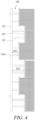
- FIG. 4 is a top view illustrating the heat exchanger according to the first exemplary embodiment.
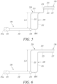
- FIG. 5 is a side view illustrating a first tube connector according to the first exemplary embodiment.
- FIG. 6 is a side view illustrating a second tube connector according to the first exemplary embodiment.
- the heat exchanger which is designated by reference numeral 150, according to the present embodiment may be a once-through heat exchanger, and in particular, a vertical once-through heat exchanger applied to the heat recovery steam generator 140.
- the heat exchanger 150 may be the high-pressure superheater 178 of the high-pressure section H3.
- the heat exchanger 150 may include a tube stack 156, a connector module 201, a plurality of heads 153, a plurality of link pipes 152, and a manifold 151.
- the tube stack 156 includes a plurality of tubes 157 and serves to overheat steam by exchanging heat with heated combustion gas.
- the tubes 157 may be connected in a straight line, and the steam flowing along the tube stack 156 may be heated by high-temperature combustion gas.
- the connector module 201 connects the tubes 157 and the heads 153 and includes a plurality of tube connectors 210 and 220.
- the tube connectors 210 and 220 may be composed of pipes each having a passage through which steam flows, and may each have a multiple curved structure.
- the tube connectors 210 and 220 may have a greater thickness than tubes 157.
- the heads 153 are connected to the connector module 201 and accommodate steam delivered from the connector module 201.
- Each of the heads 153 may be a pipe that extends parallel to the manifold 151 and has both longitudinal ends blocked.
- the heads 153 may be arranged in the longitudinal direction thereof and spaced at different distances from the manifold 151. That is, one head 153 may be spaced apart from the manifold 151 by a first distance D11, and another head 153 may be spaced apart from the manifold 151 by a second distance D12 greater than the first distance D11. In particular, the heads 153 adjacent to each other in the longitudinal direction of the manifold 151 are spaced at different distances from the manifold 151.
- the link pipes 152 may connect the heads 153 and the manifold 151.
- the manifold 151 and any one of the heads 153 may be connected by two link pipes 152.
- the link pipes 152 may each have a thickness greater than that of the connector module 201.
- the manifold 151 may be a long pipe, and the heads are connected to the manifold through the link pipes.
- the manifold 151 may have a plurality of connection pipes 151a formed for introduction or discharge of steam.
- the connector module 201 may include a first tube connector 210 and a second tube connector 220 having different shapes.
- One head 153 may be connected to both the first tube connector 210 and the second tube connector 220, and some other heads 153 may be connected to only the first tube connector 210.
- the other heads 153 may also be connected to only the second tube connector 220.
- the first tube connector 210 may include a first connection part 212 connected to associated ones of the heads 153, a first extension part 213 extending in the longitudinal direction of the link pipes 152 from the first connection part 212, a first intermediate part 214 extending in the longitudinal direction of the first connection part 212 from the first extension part 213, and a first tip part 215 extending in the longitudinal direction of the first extension part 213 from the first intermediate part 214.
- the first tip part 215 is connected to associated ones of the tubes 157.
- the first tube connector 210 may further include a bent part BD1 connected to the side ends of the associated heads 153, and the first connection part 212 may be connected to the associated heads 153 via the bent part BD1.
- the second tube connector 220 may include a second connection part 221 connected to associated ones of the heads 153, and a second tip part 225 extending in the longitudinal direction of the link pipes 152 from the second connection part 221. Meanwhile, the second tube connector 220 may further include a bent part BD1 connected to the side ends of the associated heads 153, and the second connection part 221 may be connected to the associated heads 153 via the bent part BD1.
- first connection part 212 and the second connection part 221 may be formed in parallel, and the length L11 of the first connection part 212 may be smaller than the length L12 of the second connection part 221.
- the adjacent heads 153 are spaced at different distances from the manifold 151, it is possible to absorb an amount of deformation when the tubes 157, the heads 153, and the manifold 151 are deformed by steam.
- the first and second tube connectors 210 and 220 have different shapes and the first connection part 212 has a smaller length than the second connection part 221, it is possible to minimize deformation of the arrangement of the tubes 157 caused by thermal deformation or damage to the piping caused by thermal stress.
- FIG. 7 is a perspective view illustrating the heat exchanger according to the second exemplary embodiment.
- FIG. 8 is a side view illustrating a third tube connector according to the second exemplary embodiment.
- the heat exchanger which is designated by reference numeral 150, according to the second exemplary embodiment may include a tube stack 156, a connector module 202, a plurality of heads 153, a plurality of link pipes 152, and a manifold 151.
- the heat exchanger 150 according to the second exemplary embodiment has the same structure as the heat exchanger according to the first exemplary embodiment, with the sole exception of the connector module 202, a redundant description thereof will be omitted.
- the connector module 202 connects the tubes 157 and the heads 153 and includes a plurality of tube connectors 220 and 230.
- the connector module 202 may include a second tube connector 220 and a third tube connector 230 having different shapes.
- the second tube connector 220 and the third tube connector 230 may be connected to different heads.
- the third tube connector 230 may include a third connection part 231 connected to associated ones of the heads 153, a third extension part 232 extending in the longitudinal direction of the link pipes from the third connection part 231, an inclined part 233 extending obliquely from the third extension part 232, and a third tip part 234 extending in the longitudinal direction of the third extension part 232 from the inclined part 233.
- the third tip part 234 is connected to associated ones of the tubes 157.
- the third tube connector 230 may further include a bent part BD1 connected to the side ends of the associated heads 153, and the third connection part 231 may be connected to the associated heads via the bent part BD1.
- the third connection part 231 and the second connection part 221 may be formed in parallel, and the length L 13 of the third connection part 231 may be larger than the length L 12 of the second connection part 221.
- the second and third tube connectors 220 and 230 have different shapes and the second connection part 221 has a smaller length than the third connection part 231, it is possible to reliably prevent the tubes 157 from being broken due to thermal deformation.
- FIG. 9 is a perspective view illustrating the heat exchanger according to the third exemplary embodiment.
- the heat exchanger which is designated by reference numeral 150, according to the third exemplary embodiment may include a tube stack 156, a connector module 204, a plurality of heads 153, a plurality of link pipes 152, and a manifold 151.
- the heat exchanger 150 according to the third exemplary embodiment has the same structure as the heat exchanger according to the first exemplary embodiment, with the sole exception of the connector module 204, a redundant description thereof will be omitted.
- the connector module 204 connects the tubes 157 and the heads 153 and includes a plurality of tube connectors 210, 220, and 230.
- the connector module 204 may include a first tube connector 210, a second tube connector 220, and a third tube connector 230 having different shapes.
- the first tube connector 210 and the second tube connector 220 may be connected to the same head or different heads 153.
- the third tube connector 230 may be connected to heads 153 different from those connected to the first and second tube connectors 210 and 220.
- the first and second tube connectors 210 and 220 according to the third exemplary embodiment may have the same structure as the first and second tube connectors 210 and 220 of the above-mentioned first exemplary embodiment.
- the third tube connector 230 according to the third exemplary embodiment may have the same structure as the third tube connector 230 of the second exemplary embodiment.
- the first connection part 212 has a smaller length than the second connection part 221
- the second connection part 221 has a smaller length than the third connection part 231
- FIG. 10 is a perspective view illustrating the heat exchanger according to the fourth exemplary embodiment.
- the heat exchanger which is designated by reference numeral 180, according to the fourth exemplary embodiment may include a tube stack 156, a connector module, a plurality of heads 183, a plurality of link pipes 182, and a manifold 181.
- the manifold 181 may be a long pipe, and may have a plurality of connection pipes 181a formed for introduction or discharge of steam.
- the heat exchanger 180 according to the fourth exemplary embodiment has the same structure as the heat exchanger according to the first exemplary embodiment, with the sole exception of the link pipes 182, a redundant description thereof will be omitted.
- the link pipes 182 may connect the heads 183 and the manifold 181.
- the manifold 181 and any one of the heads 183 may be connected by two link pipes 182.
- the connector module may include a first tube connector 210 and a second tube connector 220, but the present disclosure is not limited thereto.
- the link pipes coupled to different heads are formed to have different lengths, and the link pipes having different lengths are arranged obliquely to each other. Some of the link pipes may be inclined upward, while some of the link pipes may be inclined downward.
- the link pipes have different lengths and the link pipes 182 are inclined to each other, it is possible to reliably prevent the tubes from being broken due to thermal deformation.
- the once-through heat exchanger can prevent breakage and stress concentration due to thermal deformation since the heads are spaced at different distances from the manifold and the heads and the manifold are connected via the link pipes.
- the tube connectors constituting the connector module have different shapes, it is possible to minimize deformation of the arrangement of the tubes caused by thermal deformation or damage to the piping caused by thermal stress.
Landscapes
- Engineering & Computer Science (AREA)
- Mechanical Engineering (AREA)
- General Engineering & Computer Science (AREA)
- Physics & Mathematics (AREA)
- Thermal Sciences (AREA)
- Chemical & Material Sciences (AREA)
- Combustion & Propulsion (AREA)
- Heat-Exchange Devices With Radiators And Conduit Assemblies (AREA)
Abstract
Description
- Exemplary embodiments relate to a once-through heat exchanger and a combined power generation system including the same.
- A gas turbine is a power engine that mixes air compressed by a compressor with fuel for combustion and rotates a turbine with hot gas produced by the combustion. The gas turbine is used to drive a generator, an aircraft, a ship, a train, etc.
- A heat recovery steam generator (HRSG) is an energy recovery device that recovers heat from a hot gas stream to produce steam that is usable to drive a steam turbine (combined cycle). The HRSG typically includes four main components: an economizer, an evaporator, a superheater and a preheater.
- In particular, a natural circulation HRSG includes piping to facilitate a proper rate of circulation within an evaporator tube, as well as evaporator heating surfaces and drums. A once-through HRSG includes a once-through evaporator that replaces a natural circulation component, thereby providing higher facility efficiency on site and further assisting in extending HRSG life in the absence of thick wall drums.
- In the case of supercritical pressure vertical once-through HRSGs, it is difficult to ensure structural stability due to severe thermal expansion of an outlet head of a final superheater. Heating and thermal expansion of the outlet head by steam heated to a high temperature distorts tube arrangement and concentrates thermal stress, resulting in a high risk of breakage.
- Aspects of one or more exemplary embodiments provide a once-through heat exchanger, a heat recovery steam generator, and a combined power generation system including the same, which are capable of minimizing damage caused by thermal expansion.
- Additional aspects will be set forth in part in the description which follows and, in part, will become apparent from the description, or may be learned by practice of the exemplary embodiments.
- According to an aspect of an exemplary embodiment, there is provided a heat exchanger, in particular a once-through heat exchanger, that includes a tube stack including a plurality of tubes, a plurality of heads connected to the tube stack and configured to accommodate heated steam, a connector module configured to connect the tubes and the heads and including a plurality of tube connectors, a manifold connected to the heads and configured to accommodate heated steam, and a plurality of link pipes configured to connect the heads and the manifold, and the connector module includes a first tube connector and a second tube connector having different shapes.
- The heads may be spaced at different distances from the manifold.
- The heads adjacent to each other in a longitudinal direction of the manifold may be spaced at different distances from the manifold.
- The first tube connector may include a first connection part connected to associated ones of the heads. The second tube connector may include a second connection part connected to associated ones of the heads. The first connection part may have a smaller length than the second connection part.
- The first connection part and the second connection part may be formed in parallel.
- The first tube connector may further include a first extension part extending in a longitudinal direction of the link pipes from the first connection part. The first tube connector may further include a first intermediate part extending in a longitudinal direction of the first connection part from the first extension part. The first tube connector may further include a first tip part extending in a longitudinal direction of the first extension part from the first intermediate part.
- The second tube connector may further include a second tip part extending in the longitudinal direction of the link pipes from the second connection part.
- The connector module may further include a third tube connector having a different shape from the second tube connector. The third tube connector may include a third connection part connected to associated ones of the heads. The third connection part may have a larger length than the second connection part.
- The third tube connector may further include a third extension part extending in the longitudinal direction of the link pipes from the third connection part. The third tube connector may further include an inclined part extending obliquely from the third extension part. The third tube connector may further include a third tip part extending in a longitudinal direction of the third extension part from the inclined part.
- According to an aspect of another exemplary embodiment, there is provided a combined power generation system that includes a gas turbine configured to generate rotational force by burning fuel, a heat recovery steam generator configured to heat water using combustion gas discharged from the gas turbine and including a high-pressure section, a medium-pressure section, and a low-pressure section having different levels of pressure, and a steam turbine using steam heated by the heat recovery steam generator. The heat recovery steam generator includes a plurality of heat exchangers. Each of the heat exchangers includes a tube stack including a plurality of tubes, a plurality of heads connected to the tube stack and configured to accommodate heated steam, a connector module configured to connect the tubes and the heads and including a plurality of tube connectors, a manifold connected to the heads and configured to accommodate heated steam, and a plurality of link pipes configured to connect the heads and the manifold, and the connector module includes a first tube connector and a second tube connector having different shapes.
- The heads may be spaced at different distances from the manifold.
- The heads adjacent to each other in a longitudinal direction of the manifold may be spaced at different distances from the manifold.
- The first tube connector may include a first connection part connected to associated ones of the heads, the second tube connector may include a second connection part connected to associated ones of the heads, and the first connection part may have a smaller length than the second connection part.
- The first connection part and the second connection part may be formed in parallel.
- The first tube connector may further include a first extension part extending in a longitudinal direction of the link pipes from the first connection part, a first intermediate part extending in a longitudinal direction of the first connection part from the first extension part, and a first tip part extending in a longitudinal direction of the first extension part from the first intermediate part.
- The second tube connector may further include a second tip part extending in the longitudinal direction of the link pipes from the second connection part.
- The connector module may further include a third tube connector having a different shape from the second tube connector, the third tube connector may include a third connection part connected to associated ones of the heads, and the third connection part may have a larger length than the second connection part.
- The third tube connector may further include a third extension part extending in the longitudinal direction of the link pipes from the third connection part, an inclined part extending obliquely from the third extension part, and a third tip part extending in a longitudinal direction of the third extension part from the inclined part.
- It is to be understood that both the foregoing general description and the following detailed description of exemplary embodiments are exemplary and explanatory and are intended to provide further explanation of the disclosure as claimed.
- The above and other aspects will become more apparent from the following description of the exemplary embodiments with reference to the accompanying drawings, in which:
-
FIG. 1 is a configuration diagram illustrating a combined power generation system according to a first exemplary embodiment; -
FIG. 2 is a configuration diagram illustrating a heat recovery steam generator according to the first exemplary embodiment; -
FIG. 3 is a perspective view illustrating a heat exchanger according to the first exemplary embodiment; -
FIG. 4 is a top view illustrating the heat exchanger according to the first exemplary embodiment; -
FIG. 5 is a side view illustrating a first tube connector according to the first exemplary embodiment; -
FIG. 6 is a side view illustrating a second tube connector according to the first exemplary embodiment; -
FIG. 7 is a perspective view illustrating a heat exchanger according to a second exemplary embodiment; -
FIG. 8 is a side view illustrating a third tube connector according to the second exemplary embodiment; -
FIG. 9 is a perspective view illustrating a heat exchanger according to a third exemplary embodiment; and -
FIG. 10 is a perspective view illustrating a heat exchanger according to a fourth exemplary embodiment. - Various modifications and different embodiments will be described below in detail with reference to the accompanying drawings so that those skilled in the art can easily carry out the disclosure. It should be understood, however, that the present disclosure is not intended to be limited to the specific embodiments, but the present disclosure includes all modifications, equivalents or replacements that fall within the spirit and scope of the disclosure as defined in the following claims.
- The terminology used herein is for the purpose of describing specific embodiments only and is not intended to limit the scope of the disclosure. As used herein, the singular forms "a", "an" and "the" are intended to include the plural forms as well, unless the context clearly indicates otherwise. In the disclosure, terms such as "comprises", "includes", or "have/has" should be construed as designating that there are such features, integers, steps, operations, components, parts, and/or combinations thereof, not to exclude the presence or possibility of adding of one or more of other features, integers, steps, operations, components, parts, and/or combinations thereof.
- Exemplary embodiments will be described below in detail with reference to the accompanying drawings. It should be noted that like reference numerals refer to like parts throughout various drawings and exemplary embodiments. In certain embodiments, a detailed description of functions and configurations well known in the art may be omitted to avoid obscuring appreciation of the disclosure by those skilled in the art. For the same reason, some components may be exaggerated, omitted, or schematically illustrated in the accompanying drawings.
- Hereinafter, a combined power generation system according to a first exemplary embodiment will be described.
-
FIG. 1 is a configuration diagram illustrating the combined power generation system according to the first exemplary embodiment.FIG. 2 is a configuration diagram illustrating a heat recovery steam generator according to the first exemplary embodiment. - Referring to
FIGS. 1 and 2 , the combined power generation system, which is designated byreference numeral 1000, according to the first exemplary embodiment may include agas turbine 1200, asteam turbine 1600, a first generator G1, a second generator G2, and a heatrecovery steam generator 140. - In the
gas turbine 1200, thermal energy may be released by combustion of fuel in an isobaric environment after atmospheric air is sucked and compressed to a high pressure, hot combustion gas may be expanded to be converted into kinetic energy, and exhaust gas with residual energy may then be discharged to the atmosphere. - The
gas turbine 1200 may include acompressor 1210, acombustor 1220, and amain turbine 1230. Thecompressor 1210 of thegas turbine 1200 may suck air from the outside and compress the air. Thecompressor 1210 may supply thecombustor 1220 with the air compressed by compressor blades and may also supply cooling air to a hot region required for cooling in thegas turbine 1200. - Meanwhile, the
combustor 1220 may mix the compressed air, which is supplied from the outlet of thecompressor 1210, with fuel for isobaric combustion to produce combustion gas with high energy. - The high-temperature and high-pressure combustion gas produced by the
combustor 1220 is supplied to themain turbine 1230. In themain turbine 1230, the combustion gas applies impingement or reaction force to a plurality of turbine blades radially disposed on the rotary shaft of themain turbine 1230 while expanding adiabatically, so that the thermal energy of the combustion gas is converted into mechanical energy for rotating the rotary shaft. Some of the mechanical energy obtained from themain turbine 1230 is supplied as energy required to compress the air in thecompressor 1210, and the rest is utilized as effective energy, such as for driving the first generator G1 to generate electric power. - After the combustion gas flowing out of the
main turbine 1230 is cooled through the heatrecovery steam generator 140, it is purified and discharged to the outside. The heatrecovery steam generator 140 not only cools the combustion gas, but also produces high-temperature and high-pressure steam using the heat of the combustion gas to deliver the steam to thesteam turbine 1600. - The
steam turbine 1600 rotates the blades thereof using the steam produced by the heatrecovery steam generator 140 and transfers rotational energy to the second generator G2. Thesteam turbine 1600 supplies cooled steam back to the heatrecovery steam generator 140. - The first generator G1 may be connected to the
gas turbine 1200 and the second generator G2 may be connected to thesteam turbine 1600 so as to generate electric power. However, the present disclosure is not limited thereto, and a single generator may be connected to thegas turbine 1200 and thesteam turbine 1600. - The combined power generation system may be equipped with a condenser 121 for condensing steam, a
condensate reservoir 122 for storing condensed water, and acondensate pump 123 for supplying the heatrecovery steam generator 140 with the condensed water stored in thecondensate reservoir 122. - The steam flowing in the heat
recovery steam generator 140 may have two or three levels of pressure, so that the water is pressurized to two or three or more levels of pressure. In the exemplary embodiment, the heatrecovery steam generator 140 is exemplified as having three levels of pressure. - The heat
recovery steam generator 140 may include a low-pressure section H1 having a relatively low pressure, a medium-pressure section H2 having a medium pressure, and a high-pressure section H3 having a relatively high pressure. The high-pressure section H3 may be disposed adjacent to an inlet for introduction of combustion gas therethrough and be heated by high-temperature combustion gas. The low-pressure section H1 may be disposed adjacent to an outlet for discharge of combustion gas therethrough and be heated by low-temperature combustion gas. - The heat
recovery steam generator 140 includes acondensate preheater 141, a low-pressure evaporator 142, a medium-pressure economizer 143, a medium-pressure evaporator 144, a high-pressure economizer 145, and a high-pressure evaporator 146, which are installed therein. In addition, an additional superheater (not shown) may be installed upstream of each evaporator. The combustion gas flowing out of the heatrecovery steam generator 140 may be discharged via a stack. - The low-pressure section H1 includes a
condensate preheater 141, a low-pressure evaporator 142, and a low-pressure drum 147. The condensed water stored in thecondensate reservoir 122 is delivered to thecondensate preheater 141 by thecondensate pump 123. Thecondensate preheater 141 heats the condensed water by exchanging heat with combustion gas. The water heated by thecondensate preheater 141 is delivered to adeaerator 175 so that gas is removed from the condensed water. - Water is supplied from the
deaerator 175 to the low-pressure drum 147. The low-pressure evaporator 142 may be connected to the low-pressure drum 147, so that the water stored in the low-pressure drum 147 is converted into steam by heating and the steam is then supplied to the superheater after steam-water separation in the low-pressure drum 147. - The medium-pressure section H2 includes a medium-
pressure economizer 143, a medium-pressure evaporator 144, and a medium-pressure drum 148. The water in thedeaerator 175 is supplied to the medium-pressure economizer 143 by a medium-pressure pump 172. The medium-pressure economizer 143 heats the water by exchanging heat with combustion gas. The water heated in the medium-pressure economizer 143 is supplied to the low-pressure drum 148. The medium-pressure evaporator 144 may be connected to the medium-pressure drum 148, so that the water stored in the medium-pressure drum 148 is converted into steam by heating and the steam is then supplied to the superheater after steam-water separation in the medium-pressure drum 148. - The high-pressure section H3 includes a high-
pressure economizer 145, a high-pressure evaporator 146, a high-pressure drum 149, and a high-pressure superheater 178. The water in thedeaerator 175 is supplied to the high-pressure economizer 145 by a high-pressure pump 173. The high-pressure economizer 145 heats the water by exchanging heat with combustion gas. The water heated in the high-pressure economizer 145 is supplied to the high-pressure drum 149. The high-pressure evaporator 146 may be connected to the high-pressure drum 149, so that the water stored in the high-pressure drum 149 is converted into steam by heating and the steam is then supplied to the high-pressure superheater 178 after steam-water separation in the high-pressure drum 149. - The steam stored in the low-
pressure drum 147, the medium-pressure drum 148, and the high-pressure drum 149 may be supplied to low-pressure, medium-pressure, and high-pressure steam turbines, respectively. -
FIG. 3 is a perspective view illustrating a heat exchanger according to the first exemplary embodiment.FIG. 4 is a top view illustrating the heat exchanger according to the first exemplary embodiment.FIG. 5 is a side view illustrating a first tube connector according to the first exemplary embodiment.FIG. 6 is a side view illustrating a second tube connector according to the first exemplary embodiment. - Referring to
FIGS. 3 to 6 , the heat exchanger, which is designated byreference numeral 150, according to the present embodiment may be a once-through heat exchanger, and in particular, a vertical once-through heat exchanger applied to the heatrecovery steam generator 140. Alternatively, theheat exchanger 150 may be the high-pressure superheater 178 of the high-pressure section H3. - The
heat exchanger 150 may include atube stack 156, aconnector module 201, a plurality ofheads 153, a plurality oflink pipes 152, and amanifold 151. Thetube stack 156 includes a plurality oftubes 157 and serves to overheat steam by exchanging heat with heated combustion gas. Thetubes 157 may be connected in a straight line, and the steam flowing along thetube stack 156 may be heated by high-temperature combustion gas. - The
connector module 201 connects thetubes 157 and theheads 153 and includes a plurality oftube connectors tube connectors tube connectors tubes 157. - The
heads 153 are connected to theconnector module 201 and accommodate steam delivered from theconnector module 201. Each of theheads 153 may be a pipe that extends parallel to the manifold 151 and has both longitudinal ends blocked. - The
heads 153 may be arranged in the longitudinal direction thereof and spaced at different distances from themanifold 151. That is, onehead 153 may be spaced apart from the manifold 151 by a first distance D11, and anotherhead 153 may be spaced apart from the manifold 151 by a second distance D12 greater than the first distance D11. In particular, theheads 153 adjacent to each other in the longitudinal direction of the manifold 151 are spaced at different distances from themanifold 151. - The
link pipes 152 may connect theheads 153 and themanifold 151. In addition, the manifold 151 and any one of theheads 153 may be connected by twolink pipes 152. Thelink pipes 152 may each have a thickness greater than that of theconnector module 201. - The manifold 151 may be a long pipe, and the heads are connected to the manifold through the link pipes. The manifold 151 may have a plurality of
connection pipes 151a formed for introduction or discharge of steam. - Meanwhile, the
connector module 201 may include afirst tube connector 210 and asecond tube connector 220 having different shapes. Onehead 153 may be connected to both thefirst tube connector 210 and thesecond tube connector 220, and someother heads 153 may be connected to only thefirst tube connector 210. Theother heads 153 may also be connected to only thesecond tube connector 220. - The
first tube connector 210 may include afirst connection part 212 connected to associated ones of theheads 153, afirst extension part 213 extending in the longitudinal direction of thelink pipes 152 from thefirst connection part 212, a firstintermediate part 214 extending in the longitudinal direction of thefirst connection part 212 from thefirst extension part 213, and afirst tip part 215 extending in the longitudinal direction of thefirst extension part 213 from the firstintermediate part 214. Thefirst tip part 215 is connected to associated ones of thetubes 157. - Meanwhile, the
first tube connector 210 may further include a bent part BD1 connected to the side ends of the associated heads 153, and thefirst connection part 212 may be connected to the associatedheads 153 via the bent part BD1. - The
second tube connector 220 may include asecond connection part 221 connected to associated ones of theheads 153, and asecond tip part 225 extending in the longitudinal direction of thelink pipes 152 from thesecond connection part 221. Meanwhile, thesecond tube connector 220 may further include a bent part BD1 connected to the side ends of the associated heads 153, and thesecond connection part 221 may be connected to the associatedheads 153 via the bent part BD1. - Here, the
first connection part 212 and thesecond connection part 221 may be formed in parallel, and the length L11 of thefirst connection part 212 may be smaller than the length L12 of thesecond connection part 221. - As in the first exemplary embodiment, if the
adjacent heads 153 are spaced at different distances from the manifold 151, it is possible to absorb an amount of deformation when thetubes 157, theheads 153, and the manifold 151 are deformed by steam. In addition, if the first andsecond tube connectors first connection part 212 has a smaller length than thesecond connection part 221, it is possible to minimize deformation of the arrangement of thetubes 157 caused by thermal deformation or damage to the piping caused by thermal stress. - Hereinafter, a heat exchanger according to a second exemplary embodiment will be described.
-
FIG. 7 is a perspective view illustrating the heat exchanger according to the second exemplary embodiment.FIG. 8 is a side view illustrating a third tube connector according to the second exemplary embodiment. - Referring to
FIGS. 7 and 8 , the heat exchanger, which is designated byreference numeral 150, according to the second exemplary embodiment may include atube stack 156, aconnector module 202, a plurality ofheads 153, a plurality oflink pipes 152, and amanifold 151. - Since the
heat exchanger 150 according to the second exemplary embodiment has the same structure as the heat exchanger according to the first exemplary embodiment, with the sole exception of theconnector module 202, a redundant description thereof will be omitted. - The
connector module 202 connects thetubes 157 and theheads 153 and includes a plurality oftube connectors connector module 202 may include asecond tube connector 220 and athird tube connector 230 having different shapes. Thesecond tube connector 220 and thethird tube connector 230 may be connected to different heads. - The
third tube connector 230 may include athird connection part 231 connected to associated ones of theheads 153, athird extension part 232 extending in the longitudinal direction of the link pipes from thethird connection part 231, aninclined part 233 extending obliquely from thethird extension part 232, and athird tip part 234 extending in the longitudinal direction of thethird extension part 232 from theinclined part 233. Thethird tip part 234 is connected to associated ones of thetubes 157. - Meanwhile, the
third tube connector 230 may further include a bent part BD1 connected to the side ends of the associated heads 153, and thethird connection part 231 may be connected to the associated heads via the bent part BD1. - Here, the
third connection part 231 and thesecond connection part 221 may be formed in parallel, and the length L 13 of thethird connection part 231 may be larger than the length L 12 of thesecond connection part 221. - As in the second exemplary embodiment, if the second and
third tube connectors second connection part 221 has a smaller length than thethird connection part 231, it is possible to reliably prevent thetubes 157 from being broken due to thermal deformation. - Hereinafter, a heat exchanger according to a third exemplary embodiment will be described.
-
FIG. 9 is a perspective view illustrating the heat exchanger according to the third exemplary embodiment. - Referring to
FIG. 9 , the heat exchanger, which is designated byreference numeral 150, according to the third exemplary embodiment may include atube stack 156, aconnector module 204, a plurality ofheads 153, a plurality oflink pipes 152, and amanifold 151. - Since the
heat exchanger 150 according to the third exemplary embodiment has the same structure as the heat exchanger according to the first exemplary embodiment, with the sole exception of theconnector module 204, a redundant description thereof will be omitted. - The
connector module 204 connects thetubes 157 and theheads 153 and includes a plurality oftube connectors connector module 204 may include afirst tube connector 210, asecond tube connector 220, and athird tube connector 230 having different shapes. Thefirst tube connector 210 and thesecond tube connector 220 may be connected to the same head ordifferent heads 153. Meanwhile, thethird tube connector 230 may be connected toheads 153 different from those connected to the first andsecond tube connectors - The first and
second tube connectors second tube connectors third tube connector 230 according to the third exemplary embodiment may have the same structure as thethird tube connector 230 of the second exemplary embodiment. - As in the third exemplary embodiment, if the first, second, and
third tube connectors first connection part 212 has a smaller length than thesecond connection part 221, and thesecond connection part 221 has a smaller length than thethird connection part 231, it is possible to reliably prevent the tubes from being broken due to thermal deformation. - Hereinafter, a heat exchanger according to a fourth exemplary embodiment will be described.
-
FIG. 10 is a perspective view illustrating the heat exchanger according to the fourth exemplary embodiment. - Referring to
FIG. 10 , the heat exchanger, which is designated byreference numeral 180, according to the fourth exemplary embodiment may include atube stack 156, a connector module, a plurality ofheads 183, a plurality oflink pipes 182, and amanifold 181. The manifold 181 may be a long pipe, and may have a plurality ofconnection pipes 181a formed for introduction or discharge of steam. - Since the
heat exchanger 180 according to the fourth exemplary embodiment has the same structure as the heat exchanger according to the first exemplary embodiment, with the sole exception of thelink pipes 182, a redundant description thereof will be omitted. - The
link pipes 182 may connect theheads 183 and themanifold 181. In addition, the manifold 181 and any one of theheads 183 may be connected by twolink pipes 182. The connector module may include afirst tube connector 210 and asecond tube connector 220, but the present disclosure is not limited thereto. - The link pipes coupled to different heads are formed to have different lengths, and the link pipes having different lengths are arranged obliquely to each other. Some of the link pipes may be inclined upward, while some of the link pipes may be inclined downward.
- As in the fourth exemplary embodiment, if the link pipes have different lengths and the
link pipes 182 are inclined to each other, it is possible to reliably prevent the tubes from being broken due to thermal deformation. - As is apparent from the above description, the once-through heat exchanger according to the exemplary embodiments can prevent breakage and stress concentration due to thermal deformation since the heads are spaced at different distances from the manifold and the heads and the manifold are connected via the link pipes.
- In addition, since the tube connectors constituting the connector module have different shapes, it is possible to minimize deformation of the arrangement of the tubes caused by thermal deformation or damage to the piping caused by thermal stress.
- While one or more exemplary embodiments have been described with reference to the accompanying drawings, it will be apparent to those skilled in the art that various variations and modifications may be made by adding, changing, or removing components without departing from the spirit and scope of the disclosure as defined in the appended claims, and these variations and modifications fall within the spirit and scope of the disclosure as defined in the appended claims.
Claims (10)
- A once-through heat exchanger (150, 180) comprising:a tube stack (156) comprising a plurality of tubes (157);a plurality of heads (153, 183) connected to the tube stack (156) and configured to accommodate heated steam;a connector module (201, 202, 204) configured to connect the tubes (157) and the heads (153, 183) and comprising a plurality of tube connectors (210, 220, 230);a manifold connected to the heads and configured to accommodate heated steam; anda plurality of link pipes (152, 182) configured to connect the heads (153, 183) and the manifold (151, 181),wherein the connector module (201, 202, 204) comprises a first tube connector (210) and a second tube connector (220) having different shapes.
- The once-through heat exchanger (150, 180) according to claim 1, wherein the heads (153, 183) are spaced at different distances from the manifold.
- The once-through heat exchanger (150, 180) according to claim 1 or 2, wherein the heads (153, 183) adjacent to each other in a longitudinal direction of the manifold (151, 181) are spaced at different distances from the manifold (151, 181).
- The once-through heat exchanger (150, 180) according to any one of the preceding claims, wherein:the first tube connector (210) comprises a first connection part (212) connected to associated ones of the heads (153, 183), and the second tube connector comprises a second connection part (221) connected to associated ones of the heads (153, 183); andthe first connection part (212) has a smaller length than the second connection part (221).
- The once-through heat exchanger (150, 180) according to claim 4, wherein the first connection part (212) and the second connection part (221) are formed in parallel.
- The once-through heat exchanger (150, 180) according to claim 4 or 5, wherein the first tube connector (210) further comprises a first extension part (213) extending in a longitudinal direction of the link pipes (152, 182) from the first connection part (212), a first intermediate part (214) extending in a longitudinal direction of the first connection part from the first extension part (213), and a first tip part (215) extending in a longitudinal direction of the first extension part (213) from the first intermediate part (214).
- The once-through heat exchanger (150, 180) according to claim 4, 5 or 6, wherein the second tube connector (220) further comprises a second tip part (225) extending in the longitudinal direction of the link pipes (152, 182) from the second connection part (221).
- The once-through heat exchanger (150, 180) according to claim 4, 5, 6 or 7, wherein:the connector module (202) further comprises a third tube connector (230) having a different shape from the second tube connector (220); andthe third tube connector (230) comprises a third connection part (231) connected to associated ones of the heads (153, 183), and the third connection part (231) has a larger length than the second connection part (221).
- The once-through heat exchanger (150, 180) according to claim 8, wherein the third tube connector (230) further comprises a third extension part (232) extending in the longitudinal direction of the link pipes (152, 182) from the third connection part (231), an inclined part (233) extending obliquely from the third extension part (232), and a third tip part (234) extending in a longitudinal direction of the third extension part (232) from the inclined part (233).
- A combined power generation system (1000) comprising:a gas turbine (1200) configured to generate rotational force by burning fuel;a heat recovery steam generator (140) configured to heat water using combustion gas discharged from the gas turbine (1200) and comprising a high-pressure section (H3), a medium-pressure section (H2), and a low-pressure section (H1) having different levels of pressure; anda steam turbine (1600) using steam heated by the heat recovery steam generator (140),wherein the heat recovery steam generator (140) comprises a plurality of once-through heat exchangers (150, 180) according to any one of the preceding claims.
Applications Claiming Priority (1)
| Application Number | Priority Date | Filing Date | Title |
|---|---|---|---|
| KR1020220151966A KR102787601B1 (en) | 2022-11-14 | 2022-11-14 | One-through heat exchanger and combined power plant |
Publications (2)
| Publication Number | Publication Date |
|---|---|
| EP4368934A1 true EP4368934A1 (en) | 2024-05-15 |
| EP4368934B1 EP4368934B1 (en) | 2025-07-30 |
Family
ID=88779154
Family Applications (1)
| Application Number | Title | Priority Date | Filing Date |
|---|---|---|---|
| EP23209151.2A Active EP4368934B1 (en) | 2022-11-14 | 2023-11-10 | Once-through heat exchanger and combined power generation system including the same |
Country Status (2)
| Country | Link |
|---|---|
| EP (1) | EP4368934B1 (en) |
| KR (1) | KR102787601B1 (en) |
Citations (6)
| Publication number | Priority date | Publication date | Assignee | Title |
|---|---|---|---|---|
| GB1389904A (en) * | 1971-07-14 | 1975-04-09 | Babcock & Wilcox Co | Nuclear power generating systems |
| US4473035A (en) * | 1982-08-18 | 1984-09-25 | Foster Wheeler Energy Corporation | Splitter-bifurcate arrangement for a vapor generating system utilizing angularly arranged furnace boundary wall fluid flow tubes |
| US20090173072A1 (en) * | 2008-01-07 | 2009-07-09 | Alstom Technology Ltd. | Flexible assembly of recuperator for combustion turbine exhaust |
| WO2011092317A2 (en) * | 2010-01-29 | 2011-08-04 | Tanjung Citech Uk Limited | A steam generation unit |
| US20130048245A1 (en) * | 2010-05-20 | 2013-02-28 | Nooter/Eriksen, Inc. | Heat Exchanger Having Improved Drain System |
| EP2573449A1 (en) * | 2010-06-18 | 2013-03-27 | Kabushiki Kaisha Kobe Seiko Sho | Vaporizer for low-temperature liquefied gas |
Family Cites Families (4)
| Publication number | Priority date | Publication date | Assignee | Title |
|---|---|---|---|---|
| US8517008B2 (en) * | 2009-02-12 | 2013-08-27 | Babcock Power Services, Inc. | Modular solar receiver panels and solar boilers with modular receiver panels |
| KR101928374B1 (en) | 2017-05-26 | 2019-02-26 | 비에이치아이 주식회사 | Hrsg |
| US10669897B2 (en) * | 2017-12-06 | 2020-06-02 | General Electric Company | Components and systems for reducing thermal stress of heat recovery steam generators in combined cycle power plant systems |
| KR102266676B1 (en) | 2019-10-28 | 2021-06-21 | 비에이치아이 주식회사 | Retention deviation tube of lower header for hrsg |
-
2022
- 2022-11-14 KR KR1020220151966A patent/KR102787601B1/en active Active
-
2023
- 2023-11-10 EP EP23209151.2A patent/EP4368934B1/en active Active
Patent Citations (6)
| Publication number | Priority date | Publication date | Assignee | Title |
|---|---|---|---|---|
| GB1389904A (en) * | 1971-07-14 | 1975-04-09 | Babcock & Wilcox Co | Nuclear power generating systems |
| US4473035A (en) * | 1982-08-18 | 1984-09-25 | Foster Wheeler Energy Corporation | Splitter-bifurcate arrangement for a vapor generating system utilizing angularly arranged furnace boundary wall fluid flow tubes |
| US20090173072A1 (en) * | 2008-01-07 | 2009-07-09 | Alstom Technology Ltd. | Flexible assembly of recuperator for combustion turbine exhaust |
| WO2011092317A2 (en) * | 2010-01-29 | 2011-08-04 | Tanjung Citech Uk Limited | A steam generation unit |
| US20130048245A1 (en) * | 2010-05-20 | 2013-02-28 | Nooter/Eriksen, Inc. | Heat Exchanger Having Improved Drain System |
| EP2573449A1 (en) * | 2010-06-18 | 2013-03-27 | Kabushiki Kaisha Kobe Seiko Sho | Vaporizer for low-temperature liquefied gas |
Also Published As
| Publication number | Publication date |
|---|---|
| KR102787601B1 (en) | 2025-03-26 |
| US20240159172A1 (en) | 2024-05-16 |
| KR20240070284A (en) | 2024-05-21 |
| EP4368934B1 (en) | 2025-07-30 |
Similar Documents
| Publication | Publication Date | Title |
|---|---|---|
| US6499302B1 (en) | Method and apparatus for fuel gas heating in combined cycle power plants | |
| CA2019748C (en) | Combined gas and steam turbine plant with coal gasification | |
| US10900418B2 (en) | Fuel preheating system for a combustion turbine engine | |
| KR20140085001A (en) | Energy saving system for using waste heat of ship | |
| CN103062744A (en) | Heat recovery steam generator and methods of coupling same to combined cycle power plant | |
| JP2008255822A (en) | Combined cycle power generation plant and heat exchanger | |
| JP4070821B2 (en) | Gas / steam turbine equipment and cooling method of gas turbine coolant in this equipment | |
| JP7059347B2 (en) | Waste heat recovery plant and combined cycle plant | |
| US12264599B2 (en) | Synergistic heat pumped thermal storage and flexible carbon capture system | |
| US9109513B2 (en) | Combined cycle electric power generation plant and heat exchanger | |
| KR101935637B1 (en) | Combined cycle power generation system | |
| KR101247772B1 (en) | generator of ship using the organic rankine cycle | |
| CN217481350U (en) | Thermal power unit system for coupling compressed liquid carbon dioxide energy storage | |
| EP4368934B1 (en) | Once-through heat exchanger and combined power generation system including the same | |
| JP2019007380A (en) | Thermal energy recovery device | |
| US12631131B2 (en) | Once-through heat exchanger and heat recovery steam generator including the same | |
| EP4368884A1 (en) | Once-through heat exchanger and heat recovery steam generator including the same | |
| KR20140085003A (en) | Energy saving system for using waste heat of ship | |
| KR102526789B1 (en) | Combined cycle power generation system | |
| JPH11280412A (en) | Combined cycle power plant | |
| RU2686541C1 (en) | Steam-gas plant | |
| KR102803493B1 (en) | Vertical type heat recovery steam generator and combined cycle system comprising it | |
| US20250084774A1 (en) | Heat recovery in a lng plant | |
| CN116201617B (en) | An energy-saving system for coupling LNG cold energy power generation and ORC power generation for LNG fueled ships | |
| CN115288958B (en) | Indirect type photo-thermal and coal-fired complementary steam turbine system and power generation system |
Legal Events
| Date | Code | Title | Description |
|---|---|---|---|
| PUAI | Public reference made under article 153(3) epc to a published international application that has entered the european phase |
Free format text: ORIGINAL CODE: 0009012 |
|
| STAA | Information on the status of an ep patent application or granted ep patent |
Free format text: STATUS: REQUEST FOR EXAMINATION WAS MADE |
|
| 17P | Request for examination filed |
Effective date: 20231110 |
|
| AK | Designated contracting states |
Kind code of ref document: A1 Designated state(s): AL AT BE BG CH CY CZ DE DK EE ES FI FR GB GR HR HU IE IS IT LI LT LU LV MC ME MK MT NL NO PL PT RO RS SE SI SK SM TR |
|
| RBV | Designated contracting states (corrected) |
Designated state(s): AL AT BE BG CH CY CZ DE DK EE ES FI FR GB GR HR HU IE IS IT LI LT LU LV MC ME MK MT NL NO PL PT RO RS SE SI SK SM TR |
|
| GRAP | Despatch of communication of intention to grant a patent |
Free format text: ORIGINAL CODE: EPIDOSNIGR1 |
|
| STAA | Information on the status of an ep patent application or granted ep patent |
Free format text: STATUS: GRANT OF PATENT IS INTENDED |
|
| INTG | Intention to grant announced |
Effective date: 20250305 |
|
| GRAS | Grant fee paid |
Free format text: ORIGINAL CODE: EPIDOSNIGR3 |
|
| GRAA | (expected) grant |
Free format text: ORIGINAL CODE: 0009210 |
|
| STAA | Information on the status of an ep patent application or granted ep patent |
Free format text: STATUS: THE PATENT HAS BEEN GRANTED |
|
| AK | Designated contracting states |
Kind code of ref document: B1 Designated state(s): AL AT BE BG CH CY CZ DE DK EE ES FI FR GB GR HR HU IE IS IT LI LT LU LV MC ME MK MT NL NO PL PT RO RS SE SI SK SM TR |
|
| REG | Reference to a national code |
Ref country code: GB Ref legal event code: FG4D |
|
| REG | Reference to a national code |
Ref country code: CH Ref legal event code: EP |
|
| REG | Reference to a national code |
Ref country code: DE Ref legal event code: R096 Ref document number: 602023005240 Country of ref document: DE |
|
| REG | Reference to a national code |
Ref country code: IE Ref legal event code: FG4D |
|
| REG | Reference to a national code |
Ref country code: NL Ref legal event code: MP Effective date: 20250730 |
|
| REG | Reference to a national code |
Ref country code: AT Ref legal event code: MK05 Ref document number: 1819325 Country of ref document: AT Kind code of ref document: T Effective date: 20250730 |
|
| PG25 | Lapsed in a contracting state [announced via postgrant information from national office to epo] |
Ref country code: PT Free format text: LAPSE BECAUSE OF FAILURE TO SUBMIT A TRANSLATION OF THE DESCRIPTION OR TO PAY THE FEE WITHIN THE PRESCRIBED TIME-LIMIT Effective date: 20251202 |
|
| PG25 | Lapsed in a contracting state [announced via postgrant information from national office to epo] |
Ref country code: IS Free format text: LAPSE BECAUSE OF FAILURE TO SUBMIT A TRANSLATION OF THE DESCRIPTION OR TO PAY THE FEE WITHIN THE PRESCRIBED TIME-LIMIT Effective date: 20251130 |
|
| PGFP | Annual fee paid to national office [announced via postgrant information from national office to epo] |
Ref country code: DE Payment date: 20251126 Year of fee payment: 3 |
|
| PG25 | Lapsed in a contracting state [announced via postgrant information from national office to epo] |
Ref country code: NO Free format text: LAPSE BECAUSE OF FAILURE TO SUBMIT A TRANSLATION OF THE DESCRIPTION OR TO PAY THE FEE WITHIN THE PRESCRIBED TIME-LIMIT Effective date: 20251030 |
|
| REG | Reference to a national code |
Ref country code: LT Ref legal event code: MG9D |
|
| PG25 | Lapsed in a contracting state [announced via postgrant information from national office to epo] |
Ref country code: AT Free format text: LAPSE BECAUSE OF FAILURE TO SUBMIT A TRANSLATION OF THE DESCRIPTION OR TO PAY THE FEE WITHIN THE PRESCRIBED TIME-LIMIT Effective date: 20250730 |
|
| PG25 | Lapsed in a contracting state [announced via postgrant information from national office to epo] |
Ref country code: FI Free format text: LAPSE BECAUSE OF FAILURE TO SUBMIT A TRANSLATION OF THE DESCRIPTION OR TO PAY THE FEE WITHIN THE PRESCRIBED TIME-LIMIT Effective date: 20250730 |
|
| PGFP | Annual fee paid to national office [announced via postgrant information from national office to epo] |
Ref country code: IT Payment date: 20251201 Year of fee payment: 3 |
|
| PG25 | Lapsed in a contracting state [announced via postgrant information from national office to epo] |
Ref country code: HR Free format text: LAPSE BECAUSE OF FAILURE TO SUBMIT A TRANSLATION OF THE DESCRIPTION OR TO PAY THE FEE WITHIN THE PRESCRIBED TIME-LIMIT Effective date: 20250730 Ref country code: NL Free format text: LAPSE BECAUSE OF FAILURE TO SUBMIT A TRANSLATION OF THE DESCRIPTION OR TO PAY THE FEE WITHIN THE PRESCRIBED TIME-LIMIT Effective date: 20250730 |
|
| PGFP | Annual fee paid to national office [announced via postgrant information from national office to epo] |
Ref country code: FR Payment date: 20251125 Year of fee payment: 3 |
|
| PG25 | Lapsed in a contracting state [announced via postgrant information from national office to epo] |
Ref country code: GR Free format text: LAPSE BECAUSE OF FAILURE TO SUBMIT A TRANSLATION OF THE DESCRIPTION OR TO PAY THE FEE WITHIN THE PRESCRIBED TIME-LIMIT Effective date: 20251031 |
|
| PG25 | Lapsed in a contracting state [announced via postgrant information from national office to epo] |
Ref country code: SE Free format text: LAPSE BECAUSE OF FAILURE TO SUBMIT A TRANSLATION OF THE DESCRIPTION OR TO PAY THE FEE WITHIN THE PRESCRIBED TIME-LIMIT Effective date: 20250730 |
|
| PG25 | Lapsed in a contracting state [announced via postgrant information from national office to epo] |
Ref country code: LV Free format text: LAPSE BECAUSE OF FAILURE TO SUBMIT A TRANSLATION OF THE DESCRIPTION OR TO PAY THE FEE WITHIN THE PRESCRIBED TIME-LIMIT Effective date: 20250730 |
|
| PG25 | Lapsed in a contracting state [announced via postgrant information from national office to epo] |
Ref country code: BG Free format text: LAPSE BECAUSE OF FAILURE TO SUBMIT A TRANSLATION OF THE DESCRIPTION OR TO PAY THE FEE WITHIN THE PRESCRIBED TIME-LIMIT Effective date: 20250730 Ref country code: PL Free format text: LAPSE BECAUSE OF FAILURE TO SUBMIT A TRANSLATION OF THE DESCRIPTION OR TO PAY THE FEE WITHIN THE PRESCRIBED TIME-LIMIT Effective date: 20250730 |
|
| PG25 | Lapsed in a contracting state [announced via postgrant information from national office to epo] |
Ref country code: RS Free format text: LAPSE BECAUSE OF FAILURE TO SUBMIT A TRANSLATION OF THE DESCRIPTION OR TO PAY THE FEE WITHIN THE PRESCRIBED TIME-LIMIT Effective date: 20251030 |
|
| PG25 | Lapsed in a contracting state [announced via postgrant information from national office to epo] |
Ref country code: ES Free format text: LAPSE BECAUSE OF FAILURE TO SUBMIT A TRANSLATION OF THE DESCRIPTION OR TO PAY THE FEE WITHIN THE PRESCRIBED TIME-LIMIT Effective date: 20250730 |
|
| PG25 | Lapsed in a contracting state [announced via postgrant information from national office to epo] |
Ref country code: RO Free format text: LAPSE BECAUSE OF FAILURE TO SUBMIT A TRANSLATION OF THE DESCRIPTION OR TO PAY THE FEE WITHIN THE PRESCRIBED TIME-LIMIT Effective date: 20250730 |
|
| PG25 | Lapsed in a contracting state [announced via postgrant information from national office to epo] |
Ref country code: SM Free format text: LAPSE BECAUSE OF FAILURE TO SUBMIT A TRANSLATION OF THE DESCRIPTION OR TO PAY THE FEE WITHIN THE PRESCRIBED TIME-LIMIT Effective date: 20250730 |
|
| PG25 | Lapsed in a contracting state [announced via postgrant information from national office to epo] |
Ref country code: DK Free format text: LAPSE BECAUSE OF FAILURE TO SUBMIT A TRANSLATION OF THE DESCRIPTION OR TO PAY THE FEE WITHIN THE PRESCRIBED TIME-LIMIT Effective date: 20250730 |
|
| PG25 | Lapsed in a contracting state [announced via postgrant information from national office to epo] |
Ref country code: CZ Free format text: LAPSE BECAUSE OF FAILURE TO SUBMIT A TRANSLATION OF THE DESCRIPTION OR TO PAY THE FEE WITHIN THE PRESCRIBED TIME-LIMIT Effective date: 20250730 |
|
| PG25 | Lapsed in a contracting state [announced via postgrant information from national office to epo] |
Ref country code: SK Free format text: LAPSE BECAUSE OF FAILURE TO SUBMIT A TRANSLATION OF THE DESCRIPTION OR TO PAY THE FEE WITHIN THE PRESCRIBED TIME-LIMIT Effective date: 20250730 Ref country code: EE Free format text: LAPSE BECAUSE OF FAILURE TO SUBMIT A TRANSLATION OF THE DESCRIPTION OR TO PAY THE FEE WITHIN THE PRESCRIBED TIME-LIMIT Effective date: 20250730 |