EP4368923A1 - Vehicle refrigerator unit, and vehicle - Google Patents
Vehicle refrigerator unit, and vehicle Download PDFInfo
- Publication number
- EP4368923A1 EP4368923A1 EP22895311.3A EP22895311A EP4368923A1 EP 4368923 A1 EP4368923 A1 EP 4368923A1 EP 22895311 A EP22895311 A EP 22895311A EP 4368923 A1 EP4368923 A1 EP 4368923A1
- Authority
- EP
- European Patent Office
- Prior art keywords
- high voltage
- type
- voltage
- storage box
- vehicle
- Prior art date
- Legal status (The legal status is an assumption and is not a legal conclusion. Google has not performed a legal analysis and makes no representation as to the accuracy of the status listed.)
- Pending
Links
Images




Classifications
-
- F—MECHANICAL ENGINEERING; LIGHTING; HEATING; WEAPONS; BLASTING
- F25—REFRIGERATION OR COOLING; COMBINED HEATING AND REFRIGERATION SYSTEMS; HEAT PUMP SYSTEMS; MANUFACTURE OR STORAGE OF ICE; LIQUEFACTION SOLIDIFICATION OF GASES
- F25D—REFRIGERATORS; COLD ROOMS; ICE-BOXES; COOLING OR FREEZING APPARATUS NOT OTHERWISE PROVIDED FOR
- F25D29/00—Arrangement or mounting of control or safety devices
- F25D29/003—Arrangement or mounting of control or safety devices for movable devices
-
- B—PERFORMING OPERATIONS; TRANSPORTING
- B60—VEHICLES IN GENERAL
- B60H—ARRANGEMENTS OF HEATING, COOLING, VENTILATING OR OTHER AIR-TREATING DEVICES SPECIALLY ADAPTED FOR PASSENGER OR GOODS SPACES OF VEHICLES
- B60H1/00—Heating, cooling or ventilating devices
- B60H1/00007—Combined heating, ventilating, or cooling devices
- B60H1/00014—Combined heating, ventilating, or cooling devices for load cargos on load transporting vehicles
-
- B—PERFORMING OPERATIONS; TRANSPORTING
- B60—VEHICLES IN GENERAL
- B60P—VEHICLES ADAPTED FOR LOAD TRANSPORTATION OR TO TRANSPORT, TO CARRY, OR TO COMPRISE SPECIAL LOADS OR OBJECTS
- B60P3/00—Vehicles adapted to transport, to carry or to comprise special loads or objects
- B60P3/20—Refrigerated goods vehicles
-
- B—PERFORMING OPERATIONS; TRANSPORTING
- B60—VEHICLES IN GENERAL
- B60H—ARRANGEMENTS OF HEATING, COOLING, VENTILATING OR OTHER AIR-TREATING DEVICES SPECIALLY ADAPTED FOR PASSENGER OR GOODS SPACES OF VEHICLES
- B60H1/00—Heating, cooling or ventilating devices
- B60H1/00421—Driving arrangements for parts of a vehicle air-conditioning
- B60H1/00428—Driving arrangements for parts of a vehicle air-conditioning electric
Definitions
- the present disclosure relates to a vehicle refrigeration unit and a vehicle.
- Priority is claimed on Japanese Patent Application No. 2021-186086, filed on November 16, 2021 , the content of which is incorporated herein by reference.
- Such a transportation refrigerator includes a compressor that compresses a refrigerant, a drive device that drives the compressor, a control device that controls the drive device, and the like.
- Patent Literature 1 discloses a configuration equipped with a motor compressor which is disposed in a container (transportation container) and an electrical equipment unit which includes a high voltage-type apparatus driving the motor compressor and a low voltage-type apparatus controlling the driving of the motor compressor.
- the electrical equipment unit is disposed inside a box body provided on a front surface side of the container.
- This electrical equipment unit includes a first electrical equipment box which stores the high voltage-type apparatus and a second electrical equipment box which stores the low voltage-type apparatus.
- the first electrical equipment box and the second electrical equipment box are arranged side by side with a gap in the longitudinal direction.
- Patent Literature 1 Japanese Unexamined Patent Application, First Publication No. 2016-211788
- the first electrical equipment box storing the high voltage-type apparatus and the second electrical equipment box storing the low voltage-type apparatus are individually provided with a gap therebetween, but all of the first electrical equipment box and the second electrical equipment box are arranged at a low position inside the box body provided on the front surface side of the container. Therefore, when an operator opens the first electrical equipment box by mistake when performing maintenance, there is a possibility that the operator may touch the high voltage-type apparatus which is stored in the first electrical equipment box and through which a high voltage of, for example, 200 V or more flows. Therefore, for example, even when performing maintenance on the low voltage-type apparatus, the operator needs to be a person qualified to handle a high voltage. Further, the operator needs to have gloves, tools, and the like that are compatible with a high voltage. These factors may lead to a decrease in the maintainability of the transportation refrigerator and an increase in maintenance costs.
- the present disclosure has been made to solve the above-described problems and an object thereof is to provide a vehicle refrigeration unit and a vehicle capable of performing maintenance easily and safely, improving maintainability, and reducing maintenance costs.
- a vehicle refrigeration unit includes: a box-shaped container which is mountable on a vehicle body; a refrigeration cycle which includes at least an indoor heat exchanger disposed inside the container and a motor compressor compressing a refrigerant supplied to the indoor heat exchanger; a high voltage-type apparatus which includes a boost converter boosting a DC low voltage supplied from a low-voltage DC power source provided in the vehicle body side to a DC high voltage and an inverter electrically connected to the boost converter and converting the DC high voltage into an AC high voltage; a low voltage-type apparatus which is driven by a voltage lower than the high voltage-type apparatus and includes a controller controlling the operation of the inverter; a high voltage-type storage box which stores the high voltage-type apparatus; a low voltage-type storage box which stores the low voltage-type apparatus; and a box-shaped unit body which is installed in a front upper portion of the container or an upper surface of the container and stores at least the high voltage-type storage box.
- a vehicle according to the present disclosure includes the above-described vehicle refrigeration unit and a vehicle body which is disposed in front of the container and has a cabin allowing an occupant to board.
- the vehicle refrigeration unit and the vehicle of the present disclosure it is possible to perform maintenance easily and safely, improve maintainability, and reduce maintenance costs.
- a vehicle 1 includes a vehicle body 2 and a vehicle refrigeration unit 10.
- the traveling direction of the vehicle 1 is referred to as the longitudinal direction Da
- the direction orthogonal to the longitudinal direction Da and connecting the left and right sides in the traveling direction when viewed from the occupant of the vehicle 1 is referred to as the width direction Dw
- the direction orthogonal to the longitudinal direction Da and the width direction Dw is referred to as the vertical direction Dv.
- the vehicle body 2 of this embodiment is, for example, a truck.
- the vehicle body 2 includes a chassis 4 and a cabin 5 allowing an occupant to board.
- the vehicle body 2 may be, for example, a trailer.
- the vehicle body 2 includes a tractor which allows the vehicle refrigeration unit 10 to be mounted thereon and the cabin 5 which tows the tractor and allows the occupant to board.
- the chassis 4 extends in the longitudinal direction Da.
- the chassis 4 includes a plurality of wheels 4w.
- the chassis 4 includes a traveling engine (not shown) which allows the vehicle body 2 to travel.
- the engine is mounted on the front part of the chassis 4 in the longitudinal direction Da.
- the cabin 5 is disposed above the engine in the front part of the chassis 4.
- the vehicle refrigeration unit 10 is mounted on the rear part of the chassis 4 in the longitudinal direction Da.
- the cabin 5 is disposed in front of the vehicle refrigeration unit 10.
- the vehicle body 2 includes a generator 101 which is driven by the engine and a battery 102.
- the generator 101 is disposed in the vicinity of the engine.
- the generator 101 generates electric power by being rotated by the engine.
- the generator 101 is a low-voltage DC power source 100 and generates a DC low voltage DL of, for example, 27 V.
- the battery 102 is provided in the rear part of the chassis 4.
- the battery 102 is a low-voltage DC power source 100 and outputs a DC low voltage DL of, for example, 27 V.
- the vehicle refrigeration unit 10 mainly includes a container 11, a refrigeration cycle 12, and a unit body 50.
- the container 11 is mounted on the chassis 4.
- the container 11 is disposed behind the cabin 5.
- the container 11 is formed into a hollow rectangular parallelepiped shape extending in the longitudinal direction Da.
- the container 11 can store cargo that needs to be cooled or frozen.
- the container 11 includes a bottom plate 11a, a front wall 11b, a rear wall 11c, a pair of side walls 11d, and an upper plate 11e.
- the bottom plate 11a forms a bottom surface of the container 11.
- the bottom plate 11a has a rectangular shape in plan view with the long side extending in the longitudinal direction Da and is fixed on the chassis 4.
- the front wall 11b rises upward from the front edge of the bottom plate 11a.
- the rear wall 11c rises upward from the rear edge of the bottom plate 11a.
- the pair of side walls 11d respectively rise upward from both ends of the bottom plate 11a in the width direction Dw.
- the upper plate 11e forms an upper surface 11t of the container 11.
- the upper plate 11e covers a space surrounded by the front wall 11b, the rear wall 11c, and the pair of side walls 11d from above.
- the refrigeration cycle 12 includes a motor compressor 15, an indoor heat exchanger 13, an outdoor heat exchanger 14, an indoor heat exchange fan 17, an outdoor heat exchange fan 18, an expansion valve (not shown), an accumulator (not shown), and a receiver (not shown).
- the motor compressor 15, the outdoor heat exchanger 14, and the outdoor heat exchange fan 18 are built in the unit body 50 to be described later.
- the motor compressor 15 compresses a refrigerant.
- the outdoor heat exchanger 14 is disposed outside the container 11.
- the outdoor heat exchanger 14 cools the refrigerant supplied from the motor compressor 15 by heat exchange with outside air.
- the outdoor heat exchange fan 18 is disposed in the vicinity of the outdoor heat exchanger 14.
- the outdoor heat exchange fan 18 sends outside air to the outdoor heat exchanger 14.
- the refrigerant cooled by the outdoor heat exchanger 14 is supplied to the expansion valve (not shown) via the receiver (not shown).
- the expansion valve expands (depressurizes) the refrigerant supplied from the receiver.
- the indoor heat exchanger 13 is provided in an indoor unit 19 provided inside the container 11.
- the indoor heat exchanger 13 cools the atmosphere inside the container 11 by exchanging heat between the refrigerant expanded by the expansion valve and the (indoor) atmosphere inside the container 11.
- the indoor heat exchange fan 17 is provided in the indoor unit 19.
- the indoor heat exchange fan 17 is disposed in the vicinity of the indoor heat exchanger 13.
- the indoor heat exchange fan 17 cools the inside of the container 11 by sending air cooled by the indoor heat exchanger 13 inside the container 11.
- the accumulator (not shown) receives the refrigerant having passed through the indoor heat exchanger 13. The accumulator supplies the received refrigerant to the motor compressor 15.
- the vehicle refrigeration unit 10 includes a high voltage-type apparatus 20 and a low voltage-type apparatus 30 in order to operate the refrigeration cycle 12.
- the high voltage-type apparatus 20 drives the motor compressor 15.
- the high voltage-type apparatus 20 mainly includes an inverter 21, a boost converter 22, an AC-DC converter 23, and a buck converter 24.
- the boost converter 22 boosts the DC low voltage DL supplied from the battery 102 and the generator 101 serving as the low-voltage DC power source 100 provided in the vehicle body 2 to a DC high voltage DH of, for example, 270 V.
- the AC-DC converter 23 converts an AC high voltage AD of, for example, 230 V supplied from a commercial power source 200 outside the vehicle 1 into a DC high voltage DH of, for example, 270 V.
- the inverter 21 converts the DC high voltage DH supplied from the boost converter 22 or the AC-DC converter 23 into a three-phase AC high voltage AH of, for example, 270 V.
- the inverter 21 drives the motor compressor 15 by supplying the converted three-phase AC high voltage AH to the motor compressor 15.
- the buck converter 24 converts the DC high voltage DH supplied from the boost converter 22 or the AC-DC converter 23 into the DC low voltage DL of, for example, 27 V.
- the buck converter 24 supplies the converted DC low voltage DL to the low voltage-type apparatus 30.
- the low voltage-type apparatus 30 is driven by the DC low voltage DL of, for example, 27 V lower than the DC high voltage DH used for the high voltage-type apparatus 20.
- the low voltage-type apparatus 30 includes a controller 31 which controls the operation of the refrigeration cycle 12.
- the controller 31 includes a main circuit section 32 and a relay circuit section 33.
- the main circuit section 32 is operated by the DC low voltage DL supplied from the buck converter 24.
- the main circuit section 32 executes a process for controlling the operation of the inverter 21 on the basis of a pre-stored program.
- the main circuit section 32 receives an input signal of the set temperature inside the container 11 from a cabin controller 5c provided in the cabin 5.
- the main circuit section 32 outputs a control signal for operating the inverter 21 so that the temperature inside the container 11 is maintained at the set temperature on the basis of detection signals from temperature sensors (not shown) respectively provided inside the container 11 and outside the container 11.
- the control signal output from the main circuit section 32 is transmitted to the inverter 21 via a communication circuit section 28 provided in the high voltage-type apparatus 20.
- the relay circuit section 33 is electrically connected to the main circuit section 32.
- the relay circuit section 33 controls the operations of the indoor heat exchange fan 17 and the outdoor heat exchange fan 18 on the basis of the signal output from the main circuit section 32.
- the unit body 50 is installed outside the container 11.
- the unit body 50 is installed in a front upper portion lift of the front wall 11b of the container 11.
- the unit body 50 is disposed above the cabin 5.
- the unit body 50 has a box shape as a whole.
- the unit body 50 includes a frame 51 and a decorative panel 52.
- the frame 51 is fixed to the front wall 11b of the container 11.
- the frame 51 integrally includes a bottom plate 51a and a peripheral wall portion 51w.
- the peripheral wall portion 51w includes a rear plate 51b, side plates 51c and 51d, and a front plate 51e.
- the bottom plate 51a is formed in a rectangular shape that is long in the width direction Dw when viewed from above.
- the rear plate 51b rises upward from the rear edge of the bottom plate 51a.
- the rear plate 51b is fixed to the front wall 11b of the container 11.
- the side plates 51c and 51d rise upward from both side edges of the bottom plate 51a in the width direction Dw.
- the front plate 51e rises upward from the front edge of the bottom plate 51a.
- a notch 51k is formed in a part of the side plate 51d and the front plate 51e constituting the peripheral wall portion 51w.
- the decorative panel 52 integrally includes an upper panel 52a, a front panel 52b, and side panels 52c and 52d.
- the upper panel 52a is formed in a rectangular shape that is long in the width direction Dw when viewed from above.
- the front panel 52b extends downward from the front edge of the upper panel 52a.
- the side panels 52c and 52d extend downward from both sides of the upper panel 52a in the width direction Dw.
- the decorative panel 52 is removably attached to the frame 51 via a stay (not shown) or the like.
- the upper panel 52a is formed to cover the entire frame 51 from above while the decorative panel 52 is attached to the frame 51.
- the front panel 52b and the side panels 52c and 52d are arranged with a gap in the horizontal direction with respect to the frame 51 while the decorative panel 52 is attached to the frame 51.
- the motor compressor 15, the outdoor heat exchanger 14, the outdoor heat exchange fan 18, the expansion valve (not shown), the accumulator (not shown), and the receiver (not shown) constituting a part of the refrigeration cycle 12 shown in FIG. 1 are attached to the frame 51.
- the motor compressor 15, the expansion valve (not shown), the accumulator (not shown), and the receiver (not shown) are stored inside the peripheral wall portion 51w of the frame 51.
- the outdoor heat exchanger 14 is provided to cover the notch 51k and constitutes a part of the peripheral wall portion 51w.
- the upper panel 52a of the decorative panel 52 is provided with a fan opening (not shown) which sends air inside the unit body 50 to the outside by the rotation of the outdoor heat exchange fan 18.
- a high voltage-type storage box 60 and a low voltage-type storage box 70 are arranged inside the unit body 50.
- the high voltage-type storage box 60 is stored inside the peripheral wall portion 51w of the frame 51.
- the frame 51 is provided to surround the high voltage-type storage box 60 when viewed from above.
- the high voltage-type storage box 60 is disposed inside the frame 51 toward the side plate 51c on one side in the width direction Dw.
- the high voltage-type storage box 60 includes a high voltage-type box body 61 and a high voltage-type lid 63.
- the high voltage-type box body 61 is formed in a bottomed box shape having an upper opening 62 opening upward.
- the inverter 21, the boost converter 22, the AC-DC converter 23, and the buck converter 24 constituting the high voltage-type apparatus 20 are stored inside the high voltage-type box body 61.
- the high voltage-type lid 63 closes the upper opening 62 in an openable and closable manner.
- the low voltage-type storage box 70 is installed outside the peripheral wall portion 51w of the frame 51.
- the low voltage-type storage box 70 includes a low voltage-type box body 71 and a low voltage-type lid 73.
- the low voltage-type box body 71 has a side opening 72 that opens toward one side (outward) in the width direction Dw.
- a circuit board and the like constituting the main circuit section 32 and the relay circuit section 33 constituting the low voltage-type apparatus 30 are stored inside the low voltage-type box body 71.
- the low voltage-type lid 73 closes the side opening 72 in an openable and closable manner.
- the frame 51, the high voltage-type storage box 60 disposed inside the frame 51, and the low voltage-type storage box 70 attached to the outside of the frame 51 are covered with the decorative panel 52.
- one ends of power source side wirings 301A and 301B are respectively connected to the boost converter 22 and the AC-DC converter 23 inside the high voltage-type storage box 60.
- the power source side wirings 301A and 301B are led out to the outside of the high voltage-type storage box 60 and are connected to the generator 101, the battery 102, and the commercial power source 200.
- a contactor 25 and a noise filter 26 are provided in the power source side wiring 301B connected to the commercial power source 200.
- one end of the output side wiring 302 is connected to the inverter 21.
- the other end of the output side wiring 302 is led out to the outside of the high voltage-type storage box 60 and is connected to the motor compressor 15 inside the unit body 50.
- One end of a power supply wiring 303 for supplying electric power to the controller 31 is connected to the buck converter 24.
- the other end of the power supply wiring 303 is led out to the outside of the high voltage-type storage box 60 and is connected to the main circuit section 32 inside the low voltage-type storage box 70.
- the high voltage-type storage box 60 includes a detection mechanism 65 (see FIG. 6 ) and a cutoff means 66.
- the detection mechanism 65 includes a sensor such as a limit switch that detects that the high voltage-type lid 63 is opened.
- the cutoff means 66 cuts off the application of the DC high voltage DH in the high voltage-type apparatus 20 when the sensor of the detection mechanism 65 detects that the high voltage-type lid 63 is opened.
- a switch 69 is provided in the power source side wiring 301A that connects the generator 101, the battery 102, and the boost converter 22 inside the high voltage-type storage box 60.
- the switch 69 is automatically opened when the sensor of the detection mechanism 65 detects that the high voltage-type lid 63 is opened and cuts off the supply of the DC low voltage DL to the boost converter 22 via the power source side wiring 301A.
- the thick line portion indicates a portion where the current of the DC low voltage DL flows and the thin line portion indicates a portion where no current flows.
- connection terminal connected to the power source side wiring 301A on the upstream side of the switch 69 (the side of the generator 101 and the battery 102) is preferably covered with a cover such as a finger protector. Accordingly, it is possible to prevent an operator from carelessly touching a portion where the DC low voltage DL flows on the upstream side of the switch 69.
- a cutoff mechanism 25s of the contactor 25 provided in the power source side wiring 301B connected to the commercial power source 200 is provided as the cutoff means 66.
- the cutoff mechanism 25s of the contactor 25 cuts off the supply of the voltage to the downstream side (the side of the AC-DC converter 23) when the sensor of the detection mechanism 65 detects that the high voltage-type lid 63 is opened.
- a cutoff mechanism 22s built in the boost converter 22 can be used as the cutoff means 66.
- the cutoff mechanism 22s of the boost converter 22 cuts off the supply of the voltage to the downstream side (the side of the motor compressor 15) when the sensor of the detection mechanism 65 detects that the high voltage-type lid 63 is opened.
- the decorative panel 52 of the unit body 50 is first separated to expose the low voltage-type lid 73 of the low voltage-type storage box 70 as shown in FIG. 4 . Subsequently, as shown in FIG. 6 , the low voltage-type lid 73 is opened to access the inside of the low voltage-type box body 71 and to perform predetermined maintenance work.
- the high voltage-type lid 63 of the high voltage-type storage box 80 is left in a closed state. Accordingly, careless touching of the high voltage-type apparatus 20 inside the high voltage-type storage box 80 is suppressed when performing maintenance on parts other than the high voltage-type storage box 80.
- the high voltage-type storage box 60 is stored in the unit body 50 installed in the front upper portion 11ft of the container 11. Accordingly, the operator cannot access the high voltage-type storage box 60 storing the high voltage-type apparatus 20 unless the operator climbs to a high position of the container 11. Thus, it is possible to prevent the operator from carelessly touching the high voltage-type apparatus 20 to which the DC high voltage DH is applied when performing maintenance on parts other than the high voltage-type apparatus 20. Therefore, when performing maintenance on parts other than the high voltage-type apparatus 20, the operator is not limited to a person qualified to handle a high voltage. Further, it is possible to eliminate the need for special equipment and tools compatible with a high voltage. As a result, it is possible to perform maintenance easily and safely, improve maintainability, and reduce maintenance costs.
- the high voltage-type storage box 60 is surrounded by the frame 51.
- the frame 51 In order to access the high voltage-type storage box 60, it is necessary to remove the decorative panel 52 of the unit body 50 located at a high position of the container 11 and to access the frame 51 from above. From this reason, it is possible to suppress the operator from carelessly touching the high voltage-type apparatus 20 to which the DC high voltage DH is applied when performing maintenance on parts other than the high voltage-type apparatus 20.
- the high voltage-type storage box 60 includes the high voltage-type box body 61 having the upper opening 62 opening upward and the high voltage-type lid 63 which closes the upper opening 62 in an openable and closable manner.
- the low voltage-type storage box 70 is installed outside the frame 51 and is covered with the decorative panel 52.
- the low voltage-type storage box 70 is installed outside the frame 51 surrounding the high voltage-type storage box 60, it is possible to suppress the high voltage-type apparatus 20 inside the high voltage-type storage box 60 surrounded by the frame 51 from being carelessly touched when performing maintenance on the low voltage-type apparatus 30 stored in the low voltage-type storage box 70. Thus, it is possible to more effectively suppress the operator from carelessly touching the high voltage-type apparatus 20 to which the DC high voltage DH is applied when performing maintenance on parts other than the high voltage-type apparatus 20.
- the low voltage-type storage box 70 includes the low voltage-type box body 71 which has the side opening 72 opening laterally and the low voltage-type lid 73 which closes the side opening 72 in an openable and closable manner.
- the low voltage-type lid 73 which closes the side opening 72 of the low voltage-type box body 71 may be opened after removing the decorative panel 52 of the unit body 50. Since the side opening 72 opens laterally, it is easy to access the low voltage-type apparatus 30 inside the low voltage-type storage box 70 and it is possible to improve maintainability.
- the high voltage-type storage box 60 includes the cutoff means 66 which cuts off the application of the DC high voltage DH in the high voltage-type apparatus 20 when the detection mechanism 65 detects that the high voltage-type lid 63 is opened.
- the cutoff means 66 cuts off the application of the DC high voltage DH in the high voltage-type apparatus 20. Accordingly, it is possible to more effectively suppress the operator from carelessly touching the high voltage-type apparatus 20 to which the DC high voltage DH is applied.
- the low voltage-type storage box 70 is provided in the unit body 50 in which the high voltage-type storage box 60 is disposed, but the low voltage-type storage box 70 may be disposed, for example, at an appropriate location outside the unit body 50.
- the unit body 50 is disposed on the front upper portion lift of the container 11, but the present disclosure is not limited thereto. As shown in FIG. 8 , the unit body 50 may be installed in the upper surface 11t of the container 11.
- the vehicle refrigeration unit 10 and the vehicle 1 described in the embodiment are understood, for example, as below.
- the high voltage-type storage box 60 is stored in the unit body 50 installed in the front upper portion lift of the container 11 or the upper surface 11t of the container 11. Accordingly, the operator cannot access the high voltage-type storage box 60 storing the high voltage-type apparatus 20 unless the operator climbs to a high position of the container 11. Thus, it is possible to prevent the operator from carelessly touching the high voltage-type apparatus 20 to which the DC high voltage DH is applied when performing maintenance on parts other than the high voltage-type apparatus 20. Therefore, when performing maintenance on parts other than the high voltage-type apparatus 20, the operator is not limited to a person qualified to handle a high voltage. Further, it is possible to eliminate the need for special equipment and tools compatible with a high voltage. As a result, it is possible to perform maintenance easily and safely, improve maintainability, and reduce maintenance costs.
- the vehicle refrigeration unit 10 is the vehicle refrigeration unit 10 of (1), wherein the unit body 50 includes the frame 51 which is formed to surround the high voltage-type storage box 60 when viewed from above and the decorative panel 52 which covers the frame 51 and the high voltage-type storage box 60.
- the high voltage-type storage box 60 is surrounded by the frame 51.
- the vehicle refrigeration unit 10 is the vehicle refrigeration unit 10 of (2), wherein the high voltage-type storage box 60 includes the high voltage-type box body 61 which has the upper opening 62 opening upward and stores the high voltage-type apparatus 20 therein and the high voltage-type lid 63 which closes the upper opening 62 in an openable and closable manner.
- the vehicle refrigeration unit 10 according to a fourth aspect is the vehicle refrigeration unit 10 of (2) or (3), wherein the low voltage-type storage box 70 is installed outside the frame 51 and is covered with the decorative panel 52.
- the low voltage-type storage box 70 is installed outside the frame 51 surrounding the high voltage-type storage box 60, it is possible to suppress the high voltage-type apparatus 20 inside the high voltage-type storage box 60 surrounded by the frame 51 from being carelessly touched by the operator when performing maintenance on the low voltage-type apparatus 30 stored in the low voltage-type storage box 70. Thus, it is possible to more effectively suppress the operator from carelessly touching the high voltage-type apparatus 20 to which the DC high voltage DH is applied when performing maintenance on parts other than the high voltage-type apparatus 20.
- the vehicle refrigeration unit 10 is the vehicle refrigeration unit 10 of (4), wherein the low voltage-type storage box 70 includes the low voltage-type box body 71 which has the side opening 72 opening laterally and stores the low voltage-type apparatus 30 therein and the low voltage-type lid 73 which closes the side opening 72 in an openable and closable manner.
- the low voltage-type lid 73 which closes the side opening 72 of the low voltage-type box body 71 may be opened after removing the decorative panel 52 of the unit body 50. Since the side opening 72 opens laterally, it is easy to access the low voltage-type apparatus 30 inside the low voltage-type storage box 70 and it is possible to improve maintainability.
- the vehicle refrigeration unit 10 is the vehicle refrigeration unit 10 of any one of (1) to (5), wherein the high voltage-type storage box 60 includes the detection mechanism 65 which detects that the high voltage-type lid 63 is opened and the cutoff means 66 which cuts off the application of the DC high voltage DH in the high voltage-type apparatus 20 when the detection mechanism 65 detects that the high voltage-type lid 63 is opened.
- the cutoff means 66 cuts off the application of the DC high voltage DH in the high voltage-type apparatus 20. Accordingly, it is possible to more effectively suppress the operator from carelessly touching the high voltage-type apparatus 20 to which the DC high voltage DH is applied.
- Examples of the cutoff means 66 include a switch or contactor which is provided in a circuit connected to the boost converter 22 and a cutoff mechanism which is built into an electrical component to which the DC high voltage DH is applied.
- the vehicle 1 according to a seventh aspect includes: the vehicle refrigeration unit 10 according to any one of (1) to (6); and the vehicle body 2 which is disposed in front of the container 11 and has the cabin allowing the occupant to board.
- the vehicle 1 equipped with the vehicle refrigeration unit 10 it is possible to suppress the operator from carelessly touching the high voltage-type apparatus 20 to which the DC high voltage DH is applied when performing maintenance on parts other than the high voltage-type apparatus 20. As a result, it is possible to perform maintenance easily and safely, improve maintainability, and reduce maintenance costs.
Landscapes
- Engineering & Computer Science (AREA)
- Physics & Mathematics (AREA)
- Thermal Sciences (AREA)
- Mechanical Engineering (AREA)
- Health & Medical Sciences (AREA)
- Public Health (AREA)
- Transportation (AREA)
- Chemical & Material Sciences (AREA)
- Combustion & Propulsion (AREA)
- General Engineering & Computer Science (AREA)
- Devices That Are Associated With Refrigeration Equipment (AREA)
- Refrigerator Housings (AREA)
Abstract
Description
- The present disclosure relates to a vehicle refrigeration unit and a vehicle. Priority is claimed on
Japanese Patent Application No. 2021-186086, filed on November 16, 2021 - Some vehicles such as trailers that are towed by trucks and tractors are equipped with containers having transportation refrigerators. Such a transportation refrigerator includes a compressor that compresses a refrigerant, a drive device that drives the compressor, a control device that controls the drive device, and the like.
- For example,
Patent Literature 1 discloses a configuration equipped with a motor compressor which is disposed in a container (transportation container) and an electrical equipment unit which includes a high voltage-type apparatus driving the motor compressor and a low voltage-type apparatus controlling the driving of the motor compressor. In this configuration, the electrical equipment unit is disposed inside a box body provided on a front surface side of the container. This electrical equipment unit includes a first electrical equipment box which stores the high voltage-type apparatus and a second electrical equipment box which stores the low voltage-type apparatus. The first electrical equipment box and the second electrical equipment box are arranged side by side with a gap in the longitudinal direction. - [Patent Literature 1]
Japanese Unexamined Patent Application, First Publication No. 2016-211788 - However, in the configuration shown in
Patent Literature 1, the first electrical equipment box storing the high voltage-type apparatus and the second electrical equipment box storing the low voltage-type apparatus are individually provided with a gap therebetween, but all of the first electrical equipment box and the second electrical equipment box are arranged at a low position inside the box body provided on the front surface side of the container. Therefore, when an operator opens the first electrical equipment box by mistake when performing maintenance, there is a possibility that the operator may touch the high voltage-type apparatus which is stored in the first electrical equipment box and through which a high voltage of, for example, 200 V or more flows. Therefore, for example, even when performing maintenance on the low voltage-type apparatus, the operator needs to be a person qualified to handle a high voltage. Further, the operator needs to have gloves, tools, and the like that are compatible with a high voltage. These factors may lead to a decrease in the maintainability of the transportation refrigerator and an increase in maintenance costs. - The present disclosure has been made to solve the above-described problems and an object thereof is to provide a vehicle refrigeration unit and a vehicle capable of performing maintenance easily and safely, improving maintainability, and reducing maintenance costs.
- In order to solve the above-described problems, a vehicle refrigeration unit according to the present disclosure includes: a box-shaped container which is mountable on a vehicle body; a refrigeration cycle which includes at least an indoor heat exchanger disposed inside the container and a motor compressor compressing a refrigerant supplied to the indoor heat exchanger; a high voltage-type apparatus which includes a boost converter boosting a DC low voltage supplied from a low-voltage DC power source provided in the vehicle body side to a DC high voltage and an inverter electrically connected to the boost converter and converting the DC high voltage into an AC high voltage; a low voltage-type apparatus which is driven by a voltage lower than the high voltage-type apparatus and includes a controller controlling the operation of the inverter; a high voltage-type storage box which stores the high voltage-type apparatus; a low voltage-type storage box which stores the low voltage-type apparatus; and a box-shaped unit body which is installed in a front upper portion of the container or an upper surface of the container and stores at least the high voltage-type storage box.
- A vehicle according to the present disclosure includes the above-described vehicle refrigeration unit and a vehicle body which is disposed in front of the container and has a cabin allowing an occupant to board.
- According to the vehicle refrigeration unit and the vehicle of the present disclosure, it is possible to perform maintenance easily and safely, improve maintainability, and reduce maintenance costs.
-
-
FIG. 1 is a diagram showing a schematic configuration of a vehicle equipped with a vehicle refrigeration unit according to an embodiment of the present disclosure. -
FIG. 2 is a block diagram showing a functional configuration of a high voltage-type apparatus and a low voltage-type apparatus of the vehicle refrigeration unit. -
FIG. 3 is a perspective view showing a configuration of a unit body of the vehicle refrigeration unit. -
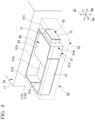
FIG. 4 is a perspective view showing a frame, a high voltage-type storage box, and a low voltage-type storage box of the unit body. -
FIG. 5 is a perspective view showing a state in which a high voltage-type lid of the high voltage-type storage box and a low voltage-type lid of the low voltage-type storage box are opened. -
FIG. 6 is a cross-sectional view showing a state when performing maintenance on the low voltage-type apparatus. -
FIG. 7 is a block diagram showing a state in which the application of a DC high voltage is cut off in the high voltage-type apparatus and the low voltage-type apparatus of the vehicle refrigeration unit. -
FIG. 8 is a diagram showing a schematic configuration of a vehicle equipped with a vehicle refrigeration unit according to a modified example of the embodiment of the present disclosure. - Hereinafter, a mode for carrying out a vehicle refrigeration unit and a vehicle according to the present disclosure will be described with reference to the accompanying drawings. However, the present disclosure is not limited to this embodiment.
- As shown in
FIG. 1 , avehicle 1 includes avehicle body 2 and avehicle refrigeration unit 10. In the following, the traveling direction of thevehicle 1 is referred to as the longitudinal direction Da, the direction orthogonal to the longitudinal direction Da and connecting the left and right sides in the traveling direction when viewed from the occupant of thevehicle 1 is referred to as the width direction Dw, and the direction orthogonal to the longitudinal direction Da and the width direction Dw is referred to as the vertical direction Dv. - The
vehicle body 2 of this embodiment is, for example, a truck. In this case, thevehicle body 2 includes a chassis 4 and acabin 5 allowing an occupant to board. Furthermore, thevehicle body 2 may be, for example, a trailer. In this case, thevehicle body 2 includes a tractor which allows thevehicle refrigeration unit 10 to be mounted thereon and thecabin 5 which tows the tractor and allows the occupant to board. - The chassis 4 extends in the longitudinal direction Da. The chassis 4 includes a plurality of
wheels 4w. The chassis 4 includes a traveling engine (not shown) which allows thevehicle body 2 to travel. The engine is mounted on the front part of the chassis 4 in the longitudinal direction Da. - The
cabin 5 is disposed above the engine in the front part of the chassis 4. Thevehicle refrigeration unit 10 is mounted on the rear part of the chassis 4 in the longitudinal direction Da. Thecabin 5 is disposed in front of thevehicle refrigeration unit 10. - As shown in
FIG. 2 , thevehicle body 2 includes agenerator 101 which is driven by the engine and abattery 102. Thegenerator 101 is disposed in the vicinity of the engine. Thegenerator 101 generates electric power by being rotated by the engine. Thegenerator 101 is a low-voltageDC power source 100 and generates a DC low voltage DL of, for example, 27 V. Thebattery 102 is provided in the rear part of the chassis 4. Thebattery 102 is a low-voltageDC power source 100 and outputs a DC low voltage DL of, for example, 27 V. - As shown in
FIG. 1 , thevehicle refrigeration unit 10 mainly includes acontainer 11, arefrigeration cycle 12, and aunit body 50. - The
container 11 is mounted on the chassis 4. Thecontainer 11 is disposed behind thecabin 5. Thecontainer 11 is formed into a hollow rectangular parallelepiped shape extending in the longitudinal direction Da. Thecontainer 11 can store cargo that needs to be cooled or frozen. Thecontainer 11 includes abottom plate 11a, afront wall 11b, arear wall 11c, a pair ofside walls 11d, and anupper plate 11e. Thebottom plate 11a forms a bottom surface of thecontainer 11. Thebottom plate 11a has a rectangular shape in plan view with the long side extending in the longitudinal direction Da and is fixed on the chassis 4. Thefront wall 11b rises upward from the front edge of thebottom plate 11a. Therear wall 11c rises upward from the rear edge of thebottom plate 11a. The pair ofside walls 11d respectively rise upward from both ends of thebottom plate 11a in the width direction Dw. Theupper plate 11e forms anupper surface 11t of thecontainer 11. Theupper plate 11e covers a space surrounded by thefront wall 11b, therear wall 11c, and the pair ofside walls 11d from above. - The
refrigeration cycle 12 includes amotor compressor 15, anindoor heat exchanger 13, anoutdoor heat exchanger 14, an indoorheat exchange fan 17, an outdoorheat exchange fan 18, an expansion valve (not shown), an accumulator (not shown), and a receiver (not shown). - The
motor compressor 15, theoutdoor heat exchanger 14, and the outdoorheat exchange fan 18 are built in theunit body 50 to be described later. Themotor compressor 15 compresses a refrigerant. Theoutdoor heat exchanger 14 is disposed outside thecontainer 11. Theoutdoor heat exchanger 14 cools the refrigerant supplied from themotor compressor 15 by heat exchange with outside air. The outdoorheat exchange fan 18 is disposed in the vicinity of theoutdoor heat exchanger 14. The outdoorheat exchange fan 18 sends outside air to theoutdoor heat exchanger 14. The refrigerant cooled by theoutdoor heat exchanger 14 is supplied to the expansion valve (not shown) via the receiver (not shown). The expansion valve expands (depressurizes) the refrigerant supplied from the receiver. - The
indoor heat exchanger 13 is provided in anindoor unit 19 provided inside thecontainer 11. Theindoor heat exchanger 13 cools the atmosphere inside thecontainer 11 by exchanging heat between the refrigerant expanded by the expansion valve and the (indoor) atmosphere inside thecontainer 11. The indoorheat exchange fan 17 is provided in theindoor unit 19. The indoorheat exchange fan 17 is disposed in the vicinity of theindoor heat exchanger 13. The indoorheat exchange fan 17 cools the inside of thecontainer 11 by sending air cooled by theindoor heat exchanger 13 inside thecontainer 11. - The accumulator (not shown) receives the refrigerant having passed through the
indoor heat exchanger 13. The accumulator supplies the received refrigerant to themotor compressor 15. - As shown in
FIG. 2 , thevehicle refrigeration unit 10 includes a high voltage-type apparatus 20 and a low voltage-type apparatus 30 in order to operate therefrigeration cycle 12. - The high voltage-
type apparatus 20 drives themotor compressor 15. The high voltage-type apparatus 20 mainly includes aninverter 21, aboost converter 22, an AC-DC converter 23, and abuck converter 24. Theboost converter 22 boosts the DC low voltage DL supplied from thebattery 102 and thegenerator 101 serving as the low-voltageDC power source 100 provided in thevehicle body 2 to a DC high voltage DH of, for example, 270 V. - The AC-
DC converter 23 converts an AC high voltage AD of, for example, 230 V supplied from acommercial power source 200 outside thevehicle 1 into a DC high voltage DH of, for example, 270 V. - The
inverter 21 converts the DC high voltage DH supplied from theboost converter 22 or the AC-DC converter 23 into a three-phase AC high voltage AH of, for example, 270 V. Theinverter 21 drives themotor compressor 15 by supplying the converted three-phase AC high voltage AH to themotor compressor 15. - The
buck converter 24 converts the DC high voltage DH supplied from theboost converter 22 or the AC-DC converter 23 into the DC low voltage DL of, for example, 27 V. Thebuck converter 24 supplies the converted DC low voltage DL to the low voltage-type apparatus 30. - The low voltage-
type apparatus 30 is driven by the DC low voltage DL of, for example, 27 V lower than the DC high voltage DH used for the high voltage-type apparatus 20. The low voltage-type apparatus 30 includes acontroller 31 which controls the operation of therefrigeration cycle 12. Thecontroller 31 includes amain circuit section 32 and arelay circuit section 33. - The
main circuit section 32 is operated by the DC low voltage DL supplied from thebuck converter 24. Themain circuit section 32 executes a process for controlling the operation of theinverter 21 on the basis of a pre-stored program. Themain circuit section 32 receives an input signal of the set temperature inside thecontainer 11 from acabin controller 5c provided in thecabin 5. Themain circuit section 32 outputs a control signal for operating theinverter 21 so that the temperature inside thecontainer 11 is maintained at the set temperature on the basis of detection signals from temperature sensors (not shown) respectively provided inside thecontainer 11 and outside thecontainer 11. The control signal output from themain circuit section 32 is transmitted to theinverter 21 via acommunication circuit section 28 provided in the high voltage-type apparatus 20. - The
relay circuit section 33 is electrically connected to themain circuit section 32. Therelay circuit section 33 controls the operations of the indoorheat exchange fan 17 and the outdoorheat exchange fan 18 on the basis of the signal output from themain circuit section 32. - As shown in
FIG. 1 , theunit body 50 is installed outside thecontainer 11. Theunit body 50 is installed in a front upper portion lift of thefront wall 11b of thecontainer 11. Theunit body 50 is disposed above thecabin 5. Theunit body 50 has a box shape as a whole. As shown inFIGS. 3 and4 , theunit body 50 includes aframe 51 and adecorative panel 52. - As shown in
FIG. 4 , theframe 51 is fixed to thefront wall 11b of thecontainer 11. Theframe 51 integrally includes abottom plate 51a and aperipheral wall portion 51w. Theperipheral wall portion 51w includes arear plate 51b,side plates front plate 51e. Thebottom plate 51a is formed in a rectangular shape that is long in the width direction Dw when viewed from above. Therear plate 51b rises upward from the rear edge of thebottom plate 51a. Therear plate 51b is fixed to thefront wall 11b of thecontainer 11. Theside plates bottom plate 51a in the width direction Dw. Thefront plate 51e rises upward from the front edge of thebottom plate 51a. Anotch 51k is formed in a part of theside plate 51d and thefront plate 51e constituting theperipheral wall portion 51w. - As shown in
FIG. 3 , thedecorative panel 52 integrally includes anupper panel 52a, afront panel 52b, andside panels upper panel 52a is formed in a rectangular shape that is long in the width direction Dw when viewed from above. Thefront panel 52b extends downward from the front edge of theupper panel 52a. Theside panels upper panel 52a in the width direction Dw. Thedecorative panel 52 is removably attached to theframe 51 via a stay (not shown) or the like. Theupper panel 52a is formed to cover theentire frame 51 from above while thedecorative panel 52 is attached to theframe 51. Thefront panel 52b and theside panels frame 51 while thedecorative panel 52 is attached to theframe 51. - The
motor compressor 15, theoutdoor heat exchanger 14, the outdoorheat exchange fan 18, the expansion valve (not shown), the accumulator (not shown), and the receiver (not shown) constituting a part of therefrigeration cycle 12 shown inFIG. 1 are attached to theframe 51. Themotor compressor 15, the expansion valve (not shown), the accumulator (not shown), and the receiver (not shown) are stored inside theperipheral wall portion 51w of theframe 51. As shown inFIG. 4 , theoutdoor heat exchanger 14 is provided to cover thenotch 51k and constitutes a part of theperipheral wall portion 51w. - The
upper panel 52a of thedecorative panel 52 is provided with a fan opening (not shown) which sends air inside theunit body 50 to the outside by the rotation of the outdoorheat exchange fan 18. - As shown in
FIGS. 4 to 6 , a high voltage-type storage box 60 and a low voltage-type storage box 70 are arranged inside theunit body 50. - The high voltage-
type storage box 60 is stored inside theperipheral wall portion 51w of theframe 51. In other words, theframe 51 is provided to surround the high voltage-type storage box 60 when viewed from above. The high voltage-type storage box 60 is disposed inside theframe 51 toward theside plate 51c on one side in the width direction Dw. The high voltage-type storage box 60 includes a high voltage-type box body 61 and a high voltage-type lid 63. The high voltage-type box body 61 is formed in a bottomed box shape having anupper opening 62 opening upward. As shown inFIG. 2 , theinverter 21, theboost converter 22, the AC-DC converter 23, and thebuck converter 24 constituting the high voltage-type apparatus 20 are stored inside the high voltage-type box body 61. As shown inFIG. 6 , the high voltage-type lid 63 closes theupper opening 62 in an openable and closable manner. - As shown in
FIGS. 4 to 6 , the low voltage-type storage box 70 is installed outside theperipheral wall portion 51w of theframe 51. The low voltage-type storage box 70 includes a low voltage-type box body 71 and a low voltage-type lid 73. The low voltage-type box body 71 has aside opening 72 that opens toward one side (outward) in the width direction Dw. As shown inFIG. 2 , a circuit board and the like constituting themain circuit section 32 and therelay circuit section 33 constituting the low voltage-type apparatus 30 are stored inside the low voltage-type box body 71. As shown inFIG. 4 , the low voltage-type lid 73 closes theside opening 72 in an openable and closable manner. - As shown in
FIGS. 3 and4 , theframe 51, the high voltage-type storage box 60 disposed inside theframe 51, and the low voltage-type storage box 70 attached to the outside of theframe 51 are covered with thedecorative panel 52. - As shown in
FIG. 2 , one ends of powersource side wirings boost converter 22 and the AC-DC converter 23 inside the high voltage-type storage box 60. The powersource side wirings type storage box 60 and are connected to thegenerator 101, thebattery 102, and thecommercial power source 200. Acontactor 25 and anoise filter 26 are provided in the powersource side wiring 301B connected to thecommercial power source 200. - Further, one end of the
output side wiring 302 is connected to theinverter 21. The other end of theoutput side wiring 302 is led out to the outside of the high voltage-type storage box 60 and is connected to themotor compressor 15 inside theunit body 50. One end of apower supply wiring 303 for supplying electric power to thecontroller 31 is connected to thebuck converter 24. The other end of thepower supply wiring 303 is led out to the outside of the high voltage-type storage box 60 and is connected to themain circuit section 32 inside the low voltage-type storage box 70. - Further, the high voltage-
type storage box 60 includes a detection mechanism 65 (seeFIG. 6 ) and a cutoff means 66. Thedetection mechanism 65 includes a sensor such as a limit switch that detects that the high voltage-type lid 63 is opened. The cutoff means 66 cuts off the application of the DC high voltage DH in the high voltage-type apparatus 20 when the sensor of thedetection mechanism 65 detects that the high voltage-type lid 63 is opened. - In this embodiment, as the cutoff means 66, a
switch 69 is provided in the powersource side wiring 301A that connects thegenerator 101, thebattery 102, and theboost converter 22 inside the high voltage-type storage box 60. As shown inFIG. 7 , theswitch 69 is automatically opened when the sensor of thedetection mechanism 65 detects that the high voltage-type lid 63 is opened and cuts off the supply of the DC low voltage DL to theboost converter 22 via the powersource side wiring 301A. In the powersource side wirings FIG. 7 , the thick line portion indicates a portion where the current of the DC low voltage DL flows and the thin line portion indicates a portion where no current flows. Accordingly, no current flows on the downstream side (the side of the boost converter 22) in relation to theswitch 69. Further, the connection terminal connected to the powersource side wiring 301A on the upstream side of the switch 69 (the side of thegenerator 101 and the battery 102) is preferably covered with a cover such as a finger protector. Accordingly, it is possible to prevent an operator from carelessly touching a portion where the DC low voltage DL flows on the upstream side of theswitch 69. - Further, a
cutoff mechanism 25s of thecontactor 25 provided in the powersource side wiring 301B connected to thecommercial power source 200 is provided as the cutoff means 66. Thecutoff mechanism 25s of thecontactor 25 cuts off the supply of the voltage to the downstream side (the side of the AC-DC converter 23) when the sensor of thedetection mechanism 65 detects that the high voltage-type lid 63 is opened. - A
cutoff mechanism 22s built in theboost converter 22 can be used as the cutoff means 66. Thecutoff mechanism 22s of theboost converter 22 cuts off the supply of the voltage to the downstream side (the side of the motor compressor 15) when the sensor of thedetection mechanism 65 detects that the high voltage-type lid 63 is opened. - In such a
vehicle refrigeration unit 10, for example, when performing maintenance such as updating a program on themain circuit section 32 of the low voltage-type apparatus 30, thedecorative panel 52 of theunit body 50 is first separated to expose the low voltage-type lid 73 of the low voltage-type storage box 70 as shown inFIG. 4 . Subsequently, as shown inFIG. 6 , the low voltage-type lid 73 is opened to access the inside of the low voltage-type box body 71 and to perform predetermined maintenance work. - At this time, the high voltage-
type lid 63 of the high voltage-type storage box 80 is left in a closed state. Accordingly, careless touching of the high voltage-type apparatus 20 inside the high voltage-type storage box 80 is suppressed when performing maintenance on parts other than the high voltage-type storage box 80. - In the
vehicle refrigeration unit 10 and thevehicle 1 of the above-described configuration, the high voltage-type storage box 60 is stored in theunit body 50 installed in the front upper portion 11ft of thecontainer 11. Accordingly, the operator cannot access the high voltage-type storage box 60 storing the high voltage-type apparatus 20 unless the operator climbs to a high position of thecontainer 11. Thus, it is possible to prevent the operator from carelessly touching the high voltage-type apparatus 20 to which the DC high voltage DH is applied when performing maintenance on parts other than the high voltage-type apparatus 20. Therefore, when performing maintenance on parts other than the high voltage-type apparatus 20, the operator is not limited to a person qualified to handle a high voltage. Further, it is possible to eliminate the need for special equipment and tools compatible with a high voltage. As a result, it is possible to perform maintenance easily and safely, improve maintainability, and reduce maintenance costs. - Further, the high voltage-
type storage box 60 is surrounded by theframe 51. Thus, in order to access the high voltage-type storage box 60, it is necessary to remove thedecorative panel 52 of theunit body 50 located at a high position of thecontainer 11 and to access theframe 51 from above. From this reason, it is possible to suppress the operator from carelessly touching the high voltage-type apparatus 20 to which the DC high voltage DH is applied when performing maintenance on parts other than the high voltage-type apparatus 20. - Further, the high voltage-
type storage box 60 includes the high voltage-type box body 61 having theupper opening 62 opening upward and the high voltage-type lid 63 which closes theupper opening 62 in an openable and closable manner. - Accordingly, in order to access the high voltage-
type apparatus 20 inside the high voltage-type storage box 60, it is necessary to open the high voltage-type lid 63 that closes theupper opening 62 of the high voltage-type box body 61. Thus, it is possible to more effectively suppress the operator from carelessly touching the high voltage-type apparatus 20 to which the DC high voltage DH is applied when performing maintenance on parts other than the high voltage-type apparatus 20. - Further, the low voltage-
type storage box 70 is installed outside theframe 51 and is covered with thedecorative panel 52. - Accordingly, since the low voltage-
type storage box 70 is installed outside theframe 51 surrounding the high voltage-type storage box 60, it is possible to suppress the high voltage-type apparatus 20 inside the high voltage-type storage box 60 surrounded by theframe 51 from being carelessly touched when performing maintenance on the low voltage-type apparatus 30 stored in the low voltage-type storage box 70. Thus, it is possible to more effectively suppress the operator from carelessly touching the high voltage-type apparatus 20 to which the DC high voltage DH is applied when performing maintenance on parts other than the high voltage-type apparatus 20. - Further, the low voltage-
type storage box 70 includes the low voltage-type box body 71 which has theside opening 72 opening laterally and the low voltage-type lid 73 which closes theside opening 72 in an openable and closable manner. - Accordingly, in order to access the low voltage-
type apparatus 30 inside the low voltage-type storage box 70, the low voltage-type lid 73 which closes theside opening 72 of the low voltage-type box body 71 may be opened after removing thedecorative panel 52 of theunit body 50. Since theside opening 72 opens laterally, it is easy to access the low voltage-type apparatus 30 inside the low voltage-type storage box 70 and it is possible to improve maintainability. - Further, the high voltage-
type storage box 60 includes the cutoff means 66 which cuts off the application of the DC high voltage DH in the high voltage-type apparatus 20 when thedetection mechanism 65 detects that the high voltage-type lid 63 is opened. - Accordingly, when the
detection mechanism 65 detects that the high voltage-type lid 63 of the high voltage-type storage box 60 is opened, the cutoff means 66 cuts off the application of the DC high voltage DH in the high voltage-type apparatus 20. Accordingly, it is possible to more effectively suppress the operator from carelessly touching the high voltage-type apparatus 20 to which the DC high voltage DH is applied. - Although the embodiment of the present disclosure has been described above in detail with reference to the drawings, the specific configuration is not limited to this embodiment, and includes design changes within the scope of the gist of the present disclosure.
- For example, the low voltage-
type storage box 70 is provided in theunit body 50 in which the high voltage-type storage box 60 is disposed, but the low voltage-type storage box 70 may be disposed, for example, at an appropriate location outside theunit body 50. - Further, in the above-described embodiment, the
unit body 50 is disposed on the front upper portion lift of thecontainer 11, but the present disclosure is not limited thereto. As shown inFIG. 8 , theunit body 50 may be installed in theupper surface 11t of thecontainer 11. - The
vehicle refrigeration unit 10 and thevehicle 1 described in the embodiment are understood, for example, as below. - (1) The
vehicle refrigeration unit 10 according to a first aspect includes: the box-shapedcontainer 11 which is mountable on thevehicle body 2; therefrigeration cycle 12 which includes at least theindoor heat exchanger 13 disposed inside thecontainer 11 and themotor compressor 15 compressing the refrigerant supplied to theindoor heat exchanger 13; the high voltage-type apparatus 20 which includes theboost converter 22 boosting the DC low voltage DL supplied from the low-voltageDC power source 100 provided on the side of thevehicle body 2 to the DC high voltage DH and theinverter 21 electrically connected to theboost converter 22 and converting the DC high voltage DH into the AC high voltage AH; the low voltage-type apparatus 30 which is driven by a voltage lower than the high voltage-type apparatus 20 and includes thecontroller 31 controlling the operation of theinverter 21; the high voltage-type storage box 60 which stores the high voltage-type apparatus 20; the low voltage-type storage box 70 which stores the low voltage-type apparatus 30; and the box-shapedunit body 50 which is installed in the front upper portion 11ft of thecontainer 11 or theupper surface 11t of thecontainer 11 and stores at least the high voltage-type storage box 60. - In the
vehicle refrigeration unit 10, at least the high voltage-type storage box 60 is stored in theunit body 50 installed in the front upper portion lift of thecontainer 11 or theupper surface 11t of thecontainer 11. Accordingly, the operator cannot access the high voltage-type storage box 60 storing the high voltage-type apparatus 20 unless the operator climbs to a high position of thecontainer 11. Thus, it is possible to prevent the operator from carelessly touching the high voltage-type apparatus 20 to which the DC high voltage DH is applied when performing maintenance on parts other than the high voltage-type apparatus 20. Therefore, when performing maintenance on parts other than the high voltage-type apparatus 20, the operator is not limited to a person qualified to handle a high voltage. Further, it is possible to eliminate the need for special equipment and tools compatible with a high voltage. As a result, it is possible to perform maintenance easily and safely, improve maintainability, and reduce maintenance costs. - (2) The
vehicle refrigeration unit 10 according to a second aspect is thevehicle refrigeration unit 10 of (1), wherein theunit body 50 includes theframe 51 which is formed to surround the high voltage-type storage box 60 when viewed from above and thedecorative panel 52 which covers theframe 51 and the high voltage-type storage box 60. - Accordingly, the high voltage-
type storage box 60 is surrounded by theframe 51. Thus, in order to access the high voltage-type storage box 60, it is necessary to remove thedecorative panel 52 of theunit body 50 located at a high position of thecontainer 11 and to access theframe 51 from above. From this reason, it is possible to suppress the operator from carelessly touching the high voltage-type apparatus 20 to which the DC high voltage DH is applied when performing maintenance on parts other than the high voltage-type apparatus 20. - (3) The
vehicle refrigeration unit 10 according to a third aspect is thevehicle refrigeration unit 10 of (2), wherein the high voltage-type storage box 60 includes the high voltage-type box body 61 which has theupper opening 62 opening upward and stores the high voltage-type apparatus 20 therein and the high voltage-type lid 63 which closes theupper opening 62 in an openable and closable manner. - Accordingly, in order to access the high voltage-
type apparatus 20 inside the high voltage-type storage box 60, it is necessary to open the high voltage-type lid 63 that closes theupper opening 62 of the high voltage-type box body 61. Thus, it is possible to more effectively suppress the operator from carelessly touching the high voltage-type apparatus 20 to which the DC high voltage DH is applied when performing maintenance on parts other than the high voltage-type apparatus 20. - (4) The
vehicle refrigeration unit 10 according to a fourth aspect is thevehicle refrigeration unit 10 of (2) or (3), wherein the low voltage-type storage box 70 is installed outside theframe 51 and is covered with thedecorative panel 52. - Accordingly, since the low voltage-
type storage box 70 is installed outside theframe 51 surrounding the high voltage-type storage box 60, it is possible to suppress the high voltage-type apparatus 20 inside the high voltage-type storage box 60 surrounded by theframe 51 from being carelessly touched by the operator when performing maintenance on the low voltage-type apparatus 30 stored in the low voltage-type storage box 70. Thus, it is possible to more effectively suppress the operator from carelessly touching the high voltage-type apparatus 20 to which the DC high voltage DH is applied when performing maintenance on parts other than the high voltage-type apparatus 20. - (5) The
vehicle refrigeration unit 10 according to a fifth aspect is thevehicle refrigeration unit 10 of (4), wherein the low voltage-type storage box 70 includes the low voltage-type box body 71 which has theside opening 72 opening laterally and stores the low voltage-type apparatus 30 therein and the low voltage-type lid 73 which closes theside opening 72 in an openable and closable manner. - Accordingly, in order to access the low voltage-
type apparatus 30 inside the low voltage-type storage box 70, the low voltage-type lid 73 which closes theside opening 72 of the low voltage-type box body 71 may be opened after removing thedecorative panel 52 of theunit body 50. Since theside opening 72 opens laterally, it is easy to access the low voltage-type apparatus 30 inside the low voltage-type storage box 70 and it is possible to improve maintainability. - (6) The
vehicle refrigeration unit 10 according to a sixth aspect is thevehicle refrigeration unit 10 of any one of (1) to (5), wherein the high voltage-type storage box 60 includes thedetection mechanism 65 which detects that the high voltage-type lid 63 is opened and the cutoff means 66 which cuts off the application of the DC high voltage DH in the high voltage-type apparatus 20 when thedetection mechanism 65 detects that the high voltage-type lid 63 is opened. - Accordingly, when the
detection mechanism 65 detects that the high voltage-type lid 63 of the high voltage-type storage box 60 is opened, the cutoff means 66 cuts off the application of the DC high voltage DH in the high voltage-type apparatus 20. Accordingly, it is possible to more effectively suppress the operator from carelessly touching the high voltage-type apparatus 20 to which the DC high voltage DH is applied. - Examples of the cutoff means 66 include a switch or contactor which is provided in a circuit connected to the
boost converter 22 and a cutoff mechanism which is built into an electrical component to which the DC high voltage DH is applied. - (7) The
vehicle 1 according to a seventh aspect includes: thevehicle refrigeration unit 10 according to any one of (1) to (6); and thevehicle body 2 which is disposed in front of thecontainer 11 and has the cabin allowing the occupant to board. - Accordingly, in the
vehicle 1 equipped with thevehicle refrigeration unit 10, it is possible to suppress the operator from carelessly touching the high voltage-type apparatus 20 to which the DC high voltage DH is applied when performing maintenance on parts other than the high voltage-type apparatus 20. As a result, it is possible to perform maintenance easily and safely, improve maintainability, and reduce maintenance costs. - According to the aspects of the present disclosure, it is possible to perform maintenance easily and safely, improve maintainability, and reduce maintenance costs.
-
- 1 Vehicle
- 2 Vehicle body
- 4 Chassis
- 4w Wheel
- 5 Cabin
- 5c Cabin controller
- 10 Vehicle refrigeration unit
- 11 Container
- 11a Bottom plate
- 11b Front wall
- 11c Rear wall
- 11d Side wall
- 11e Upper plate
- lift Front upper portion
- 11t Upper surface
- 12 Refrigeration cycle
- 13 Indoor heat exchanger
- 14 Outdoor heat exchanger
- 15 Motor compressor
- 17 Indoor heat exchange fan
- 18 Outdoor heat exchange fan
- 19 Indoor unit
- 20 High voltage-type apparatus
- 21 Inverter
- 22 Boost converter
- 22s Cutoff mechanism
- 23 AC-DC converter
- 24 Buck converter
- 25 Contactor
- 25s Cutoff mechanism
- 26 Noise filter
- 28 Communication circuit section
- 30 Low voltage-type apparatus
- 31 Controller
- 32 Main circuit section
- 33 Relay circuit section
- 50 Unit body
- 51 Frame
- 51a Bottom plate
- 51b Rear plate
- 51c Side plate
- 51d Side plate
- 51e Front plate
- 51k Notch
- 51w Peripheral wall portion
- 52 Decorative panel
- 52a Upper panel
- 52b Front panel
- 52c Side panel
- 52d Side panel
- 60 High voltage-type storage box
- 61 High voltage-type box body
- 62 Upper opening
- 63 High voltage-type lid
- 65 Detection mechanism
- 66 Cutoff means
- 69 Switch
- 70 Low voltage-type storage box
- 71 Low voltage-type box body
- 72 Side opening
- 73 Low voltage-type lid
- 80 High voltage-type storage box
- 100 Low-voltage DC power source
- 101 Generator
- 102 Battery
- 200 Commercial power source
- 301A Power source side wiring
- 301B Power source side wiring
- 302 Output side wiring
- 303 Power supply wiring
- AD AC high voltage
- AH Three-phase AC high voltage
- DH DC high voltage
- DL DC low voltage
- Da Direction
- Dv Vertical direction
- Dw Width direction
Claims (7)
- A vehicle refrigeration unit comprising:a box-shaped container which is mountable on a vehicle body;a refrigeration cycle which includes at least an indoor heat exchanger disposed inside the container and a motor compressor compressing a refrigerant supplied to the indoor heat exchanger;a high voltage-type apparatus which includes a boost converter boosting a DC low voltage supplied from a low-voltage DC power source provided in the vehicle body side to a DC high voltage and an inverter electrically connected to the boost converter and converting the DC high voltage into an AC high voltage;a low voltage-type apparatus which is driven by a voltage lower than the high voltage-type apparatus and includes a controller controlling the operation of the inverter;a high voltage-type storage box which stores the high voltage-type apparatus;a low voltage-type storage box which stores the low voltage-type apparatus; anda box-shaped unit body which is installed in a front upper portion of the container or an upper surface of the container and stores at least the high voltage-type storage box.
- The vehicle refrigeration unit according to claim 1,
wherein the unit body includes a frame which is fixed to the vehicle body and is formed to surround the high voltage-type storage box when viewed from above and a decorative panel which covers the frame and the high voltage-type storage box. - The vehicle refrigeration unit according to claim 2,
wherein the high voltage-type storage box includes a high voltage-type box body which has an upper opening that opens upward and stores the high voltage-type apparatus therein and a high voltage-type lid which closes the upper opening in an openable and closable manner. - The vehicle refrigeration unit according to claim 2 or 3,
wherein the low voltage-type storage box is installed outside the frame and is covered with the decorative panel. - The vehicle refrigeration unit according to claim 4,
wherein the low voltage-type storage box includes a low voltage-type box body which has a side opening that opens laterally and stores the low voltage-type apparatus therein and a low voltage-type lid which closes the side opening in an openable and closable manner. - The vehicle refrigeration unit according to claim 3,
wherein the high voltage-type storage box includes a detection mechanism which detects that the high voltage-type lid is opened and a cutoff means which cuts off the application of the DC high voltage in the high voltage-type apparatus when the detection mechanism detects that the high voltage-type lid is opened. - A vehicle comprising:the vehicle refrigeration unit according to any one of claims 1 to 6; anda vehicle body which is disposed in front of the container and has a cabin allowing an occupant to board.
Applications Claiming Priority (2)
| Application Number | Priority Date | Filing Date | Title |
|---|---|---|---|
| JP2021186086A JP7851105B2 (en) | 2021-11-16 | 2021-11-16 | Vehicle refrigeration unit, vehicle |
| PCT/JP2022/038676 WO2023090025A1 (en) | 2021-11-16 | 2022-10-18 | Vehicle refrigerator unit, and vehicle |
Publications (2)
| Publication Number | Publication Date |
|---|---|
| EP4368923A1 true EP4368923A1 (en) | 2024-05-15 |
| EP4368923A4 EP4368923A4 (en) | 2024-12-11 |
Family
ID=86396608
Family Applications (1)
| Application Number | Title | Priority Date | Filing Date |
|---|---|---|---|
| EP22895311.3A Pending EP4368923A4 (en) | 2021-11-16 | 2022-10-18 | VEHICLE REFRIGERATOR UNIT AND VEHICLE |
Country Status (3)
| Country | Link |
|---|---|
| EP (1) | EP4368923A4 (en) |
| JP (1) | JP7851105B2 (en) |
| WO (1) | WO2023090025A1 (en) |
Families Citing this family (1)
| Publication number | Priority date | Publication date | Assignee | Title |
|---|---|---|---|---|
| JP2025158852A (en) * | 2024-04-05 | 2025-10-17 | 三菱重工サーマルシステムズ株式会社 | Transport refrigeration equipment |
Family Cites Families (9)
| Publication number | Priority date | Publication date | Assignee | Title |
|---|---|---|---|---|
| JPS5631139Y2 (en) * | 1975-10-15 | 1981-07-24 | ||
| JPH11136812A (en) * | 1997-10-28 | 1999-05-21 | Kojima Press Co Ltd | Switch device |
| JP4123906B2 (en) * | 2002-11-12 | 2008-07-23 | 日産自動車株式会社 | High-voltage component housing structure |
| US20110162395A1 (en) * | 2008-09-17 | 2011-07-07 | Bruno Chakiachvili | Electrically powered transport refrigeration units |
| JP6181684B2 (en) * | 2015-02-27 | 2017-08-16 | 株式会社デンソーエアクール | Roof mounted unit and vehicle air conditioning system including roof mounted unit |
| JP6667210B2 (en) * | 2015-05-11 | 2020-03-18 | 三菱重工サーマルシステムズ株式会社 | Transport refrigerators and trailers |
| JP6614213B2 (en) * | 2017-08-09 | 2019-12-04 | マツダ株式会社 | Harness wiring structure in the engine room |
| JP7137334B2 (en) * | 2018-03-29 | 2022-09-14 | 三菱重工サーマルシステムズ株式会社 | Refrigerator unit for cold storage vehicle |
| JP7581659B2 (en) | 2020-05-27 | 2024-11-13 | ヤマハ株式会社 | Golf club head and golf club |
-
2021
- 2021-11-16 JP JP2021186086A patent/JP7851105B2/en active Active
-
2022
- 2022-10-18 EP EP22895311.3A patent/EP4368923A4/en active Pending
- 2022-10-18 WO PCT/JP2022/038676 patent/WO2023090025A1/en not_active Ceased
Also Published As
| Publication number | Publication date |
|---|---|
| JP7851105B2 (en) | 2026-04-24 |
| EP4368923A4 (en) | 2024-12-11 |
| JP2023073552A (en) | 2023-05-26 |
| WO2023090025A1 (en) | 2023-05-25 |
Similar Documents
| Publication | Publication Date | Title |
|---|---|---|
| US11554629B2 (en) | Hybrid power conversion system for a refrigerated transport vehicle and method | |
| EP2903860B1 (en) | Systems and methods for powering a transport refrigeration system | |
| US10974582B2 (en) | Electric vehicle | |
| US11235671B2 (en) | Electrically powered vehicle | |
| US9539908B2 (en) | Contactless power supply device | |
| EP1897843A2 (en) | Hybrid industrial vehicle | |
| CN105480070B (en) | Electric vehicle | |
| US20120118659A1 (en) | Saddle-ride-type electrically operated vehicle | |
| US20140151138A1 (en) | Automobile having electric vehicle drive motor | |
| EP2985188A1 (en) | Contactless power-supply device | |
| JP7693898B2 (en) | Tractor | |
| JP6431882B2 (en) | vehicle | |
| JP2019174062A (en) | Cold insulation vehicle refrigerator unit | |
| JP7851105B2 (en) | Vehicle refrigeration unit, vehicle | |
| JP5895072B2 (en) | Vehicle connection structure | |
| JP2017132289A (en) | Power source car | |
| JP2014051172A (en) | Vehicle connection part arrangement structure | |
| US20110116950A1 (en) | Inverter-integrated electric compressor | |
| JP5962905B2 (en) | Vehicle power supply system | |
| CN115912922A (en) | Energy dissipation for power supplies of transport climate control systems | |
| CN211457691U (en) | Electric cabinet of orchard operation vehicle | |
| JP5939387B2 (en) | Vehicle power supply system | |
| CN207311125U (en) | A kind of high pressure box mounting structure | |
| EP4494905A1 (en) | Electrically isolating hazardous voltage from vehicle powered transport climate control system | |
| US20260138415A1 (en) | Electrically isolating hazardous voltage from vehicle powered transport climate control system |
Legal Events
| Date | Code | Title | Description |
|---|---|---|---|
| STAA | Information on the status of an ep patent application or granted ep patent |
Free format text: STATUS: THE INTERNATIONAL PUBLICATION HAS BEEN MADE |
|
| PUAI | Public reference made under article 153(3) epc to a published international application that has entered the european phase |
Free format text: ORIGINAL CODE: 0009012 |
|
| STAA | Information on the status of an ep patent application or granted ep patent |
Free format text: STATUS: REQUEST FOR EXAMINATION WAS MADE |
|
| 17P | Request for examination filed |
Effective date: 20240205 |
|
| AK | Designated contracting states |
Kind code of ref document: A1 Designated state(s): AL AT BE BG CH CY CZ DE DK EE ES FI FR GB GR HR HU IE IS IT LI LT LU LV MC ME MK MT NL NO PL PT RO RS SE SI SK SM TR |
|
| A4 | Supplementary search report drawn up and despatched |
Effective date: 20241107 |
|
| RIC1 | Information provided on ipc code assigned before grant |
Ipc: B60H 1/00 20060101ALI20241101BHEP Ipc: B60P 3/20 20060101ALI20241101BHEP Ipc: F25D 23/06 20060101ALI20241101BHEP Ipc: F25B 1/00 20060101ALI20241101BHEP Ipc: F25D 29/00 20060101ALI20241101BHEP Ipc: F25D 11/00 20060101AFI20241101BHEP |
|
| DAV | Request for validation of the european patent (deleted) | ||
| DAX | Request for extension of the european patent (deleted) | ||
| GRAP | Despatch of communication of intention to grant a patent |
Free format text: ORIGINAL CODE: EPIDOSNIGR1 |
|
| STAA | Information on the status of an ep patent application or granted ep patent |
Free format text: STATUS: GRANT OF PATENT IS INTENDED |
|
| INTG | Intention to grant announced |
Effective date: 20260105 |
|
| GRAS | Grant fee paid |
Free format text: ORIGINAL CODE: EPIDOSNIGR3 |
|
| GRAA | (expected) grant |
Free format text: ORIGINAL CODE: 0009210 |
|
| STAA | Information on the status of an ep patent application or granted ep patent |
Free format text: STATUS: THE PATENT HAS BEEN GRANTED |