EP4368860A1 - Cassette seal - Google Patents
Cassette seal Download PDFInfo
- Publication number
- EP4368860A1 EP4368860A1 EP23197649.9A EP23197649A EP4368860A1 EP 4368860 A1 EP4368860 A1 EP 4368860A1 EP 23197649 A EP23197649 A EP 23197649A EP 4368860 A1 EP4368860 A1 EP 4368860A1
- Authority
- EP
- European Patent Office
- Prior art keywords
- axially
- extending
- radially
- region
- sealing
- Prior art date
- Legal status (The legal status is an assumption and is not a legal conclusion. Google has not performed a legal analysis and makes no representation as to the accuracy of the status listed.)
- Granted
Links
Images


Classifications
-
- F—MECHANICAL ENGINEERING; LIGHTING; HEATING; WEAPONS; BLASTING
- F16—ENGINEERING ELEMENTS AND UNITS; GENERAL MEASURES FOR PRODUCING AND MAINTAINING EFFECTIVE FUNCTIONING OF MACHINES OR INSTALLATIONS; THERMAL INSULATION IN GENERAL
- F16J—PISTONS; CYLINDERS; SEALINGS
- F16J15/00—Sealings
- F16J15/16—Sealings between relatively-moving surfaces
- F16J15/32—Sealings between relatively-moving surfaces with elastic sealings, e.g. O-rings
- F16J15/3248—Sealings between relatively-moving surfaces with elastic sealings, e.g. O-rings provided with casings or supports
- F16J15/3252—Sealings between relatively-moving surfaces with elastic sealings, e.g. O-rings provided with casings or supports with rigid casings or supports
- F16J15/3256—Sealings between relatively-moving surfaces with elastic sealings, e.g. O-rings provided with casings or supports with rigid casings or supports comprising two casing or support elements, one attached to each surface, e.g. cartridge or cassette seals
-
- F—MECHANICAL ENGINEERING; LIGHTING; HEATING; WEAPONS; BLASTING
- F16—ENGINEERING ELEMENTS AND UNITS; GENERAL MEASURES FOR PRODUCING AND MAINTAINING EFFECTIVE FUNCTIONING OF MACHINES OR INSTALLATIONS; THERMAL INSULATION IN GENERAL
- F16J—PISTONS; CYLINDERS; SEALINGS
- F16J15/00—Sealings
- F16J15/16—Sealings between relatively-moving surfaces
- F16J15/164—Sealings between relatively-moving surfaces the sealing action depending on movements; pressure difference, temperature or presence of leaking fluid
-
- F—MECHANICAL ENGINEERING; LIGHTING; HEATING; WEAPONS; BLASTING
- F16—ENGINEERING ELEMENTS AND UNITS; GENERAL MEASURES FOR PRODUCING AND MAINTAINING EFFECTIVE FUNCTIONING OF MACHINES OR INSTALLATIONS; THERMAL INSULATION IN GENERAL
- F16J—PISTONS; CYLINDERS; SEALINGS
- F16J15/00—Sealings
- F16J15/16—Sealings between relatively-moving surfaces
- F16J15/32—Sealings between relatively-moving surfaces with elastic sealings, e.g. O-rings
- F16J15/3204—Sealings between relatively-moving surfaces with elastic sealings, e.g. O-rings with at least one lip
- F16J15/3208—Sealings between relatively-moving surfaces with elastic sealings, e.g. O-rings with at least one lip provided with tension elements, e.g. elastic rings
- F16J15/3212—Sealings between relatively-moving surfaces with elastic sealings, e.g. O-rings with at least one lip provided with tension elements, e.g. elastic rings with metal springs
-
- F—MECHANICAL ENGINEERING; LIGHTING; HEATING; WEAPONS; BLASTING
- F16—ENGINEERING ELEMENTS AND UNITS; GENERAL MEASURES FOR PRODUCING AND MAINTAINING EFFECTIVE FUNCTIONING OF MACHINES OR INSTALLATIONS; THERMAL INSULATION IN GENERAL
- F16J—PISTONS; CYLINDERS; SEALINGS
- F16J15/00—Sealings
- F16J15/16—Sealings between relatively-moving surfaces
- F16J15/32—Sealings between relatively-moving surfaces with elastic sealings, e.g. O-rings
- F16J15/3204—Sealings between relatively-moving surfaces with elastic sealings, e.g. O-rings with at least one lip
- F16J15/3232—Sealings between relatively-moving surfaces with elastic sealings, e.g. O-rings with at least one lip having two or more lips
-
- F—MECHANICAL ENGINEERING; LIGHTING; HEATING; WEAPONS; BLASTING
- F16—ENGINEERING ELEMENTS AND UNITS; GENERAL MEASURES FOR PRODUCING AND MAINTAINING EFFECTIVE FUNCTIONING OF MACHINES OR INSTALLATIONS; THERMAL INSULATION IN GENERAL
- F16J—PISTONS; CYLINDERS; SEALINGS
- F16J15/00—Sealings
- F16J15/16—Sealings between relatively-moving surfaces
- F16J15/32—Sealings between relatively-moving surfaces with elastic sealings, e.g. O-rings
- F16J15/3204—Sealings between relatively-moving surfaces with elastic sealings, e.g. O-rings with at least one lip
- F16J15/3232—Sealings between relatively-moving surfaces with elastic sealings, e.g. O-rings with at least one lip having two or more lips
- F16J15/3236—Sealings between relatively-moving surfaces with elastic sealings, e.g. O-rings with at least one lip having two or more lips with at least one lip for each surface, e.g. U-cup packings
-
- F—MECHANICAL ENGINEERING; LIGHTING; HEATING; WEAPONS; BLASTING
- F16—ENGINEERING ELEMENTS AND UNITS; GENERAL MEASURES FOR PRODUCING AND MAINTAINING EFFECTIVE FUNCTIONING OF MACHINES OR INSTALLATIONS; THERMAL INSULATION IN GENERAL
- F16J—PISTONS; CYLINDERS; SEALINGS
- F16J15/00—Sealings
- F16J15/16—Sealings between relatively-moving surfaces
- F16J15/32—Sealings between relatively-moving surfaces with elastic sealings, e.g. O-rings
- F16J15/3268—Mounting of sealing rings
- F16J15/3276—Mounting of sealing rings with additional static sealing between the sealing, or its casing or support, and the surface on which it is mounted
-
- F—MECHANICAL ENGINEERING; LIGHTING; HEATING; WEAPONS; BLASTING
- F16—ENGINEERING ELEMENTS AND UNITS; GENERAL MEASURES FOR PRODUCING AND MAINTAINING EFFECTIVE FUNCTIONING OF MACHINES OR INSTALLATIONS; THERMAL INSULATION IN GENERAL
- F16J—PISTONS; CYLINDERS; SEALINGS
- F16J15/00—Sealings
- F16J15/16—Sealings between relatively-moving surfaces
- F16J15/34—Sealings between relatively-moving surfaces with slip-ring pressed against a more or less radial face on one member
- F16J15/3436—Pressing means
- F16J15/3456—Pressing means without external means for pressing the ring against the face, e.g. slip-ring with a resilient lip
Definitions
- Embodiments of the present disclosure relate generally to a cassette seal for sealing an annular gap between a rotatable shaft and an aperture in a housing through which the shaft passes.
- Embodiments of the present disclosure relate in particular, but not exclusively, to such a cassette seal for a final drive in an axle of a mobile machine such as a tractor or other agricultural vehicle.
- Cassette seals (also referred to as cartridge seals) are known for sealing between a shaft which in use is rotated about its axis and a surface of an aperture in a housing through which the shaft projects. Often the housing will contain oil and the cassette seal includes oil seals for preventing oil escaping through the aperture about the shaft.
- This type of known cassette seal has a rotational inner member which is fitted to and rotates with the shaft, and a stationary outer member, which is an interference fit in the aperture of the housing and so remains static.
- the rotational member typically carries an elastomeric sealing member that forms a static oil seal with the shaft, and the outer member carries another elastomeric sealing member that forms a static oil seal with the surface the housing aperture.
- the outer member also has an oil sealing lip resiliently biased onto a sealing surface formed on the rotational inner member so as to form a rotary oil seal between stationary and rotational members.
- the inner member In applications where the aperture is in an outer wall of the housing so that the shaft projects externally of the housing through the aperture, and where the cassette seal separates an internal volume of the housing at an axially inner end of the cassette seal from atmosphere at an axially outer end of the cassette seal, it is also known for the inner member to carry secondary or dust sealing lips that engage a sealing surface of the outer member at a position axially outboard of the oil sealing lip. The secondary sealing lips help to prevent dust and other contaminates entering the cassette seal between the stationary and rotational members from reaching the oil sealing lip.
- aspects of the invention include a cassette seal and a mobile machine having an axle with a final drive incorporating such a cassette seal between a drive shaft and an aperture of a housing of the final drive through which the drive shaft projects.
- a cassette seal for sealing an annular gap between a shaft having a longitudinal axis and mounted for rotation about its longitudinal axis and a surface defining an aperture in a housing through which the shaft projects and for separating an internal volume of the housing at an axially inner end of the cassette seal from atmosphere at an axially outer end of the cassette seal
- the cassette seal having an annular rotational member for mounting rotationally fast with the shaft and an annular stationary member for mounting to the surface of the housing defining the aperture
- the stationary member comprising a sealing element for forming a static oil seal with the surface of the housing and the rotational member comprising a sealing element for forming a static oil seal with the shaft, the stationary member encircling at least part of the rotational member and having a sealing lip resiliently engaging a sealing surface on the rotational member to form an oil seal between the stationary and rotational members
- the rotational member comprising at least one secondary sealing lip engaging a sealing surface of the stationary member at a position axially outboard of the
- the at least one exterior sealing lip may act as a further level of protection in addition to the at least one secondary sealing lip in preventing dust, dirt and other contaminants from entering the cassette seal as far as the oil sealing lip. It is an advantage that any contaminants that do pass the at least one exterior sealing lip can be ejected back past the exterior sealing lip when the inner member is rotated with the shaft due to centrifugal force.
- the rotational member may comprise a cover portion located axially outboard of the at least one exterior sealing lip, the cover portion extending radially outward and axially inward to at least partially enclose the exterior sealing lip, the cover portion being more rigid than the exterior sealing lip.
- the stationary member may comprise a first reinforcing member having an axially extending cylindrical region for engagement with the surface of the housing defining the aperture and a radially extending region at an axial outer end of the axially extending cylindrical region, wherein the radially extending portion of the stationary member may be defined by the radially extending region of the reinforcing member.
- the radially extending portion of the stationary member extends radially outward, the arrangement configured such that in use, the radially extending portion of the stationary member locates adjacent an outer surface of the housing which surface extends radially about the aperture.
- the rotational member may comprise two of the exterior sealing lips radially spaced apart.
- the rotational member comprises a second reinforcing member having a first axially extending cylindrical region for location adjacent the shaft and carrying a first elastomeric sealing member which comprises the sealing element for forming a static oil seal with the shaft, the second reinforcing member having a first radially extending region extending radially outward at an axial outer end of the first axially extending cylindrical region, a second axially extending cylindrical region extending axially outward from a radially outer end of the first radially extending region, and a second radially extending region extending radially outward at an axially outer end of the second axially extending cylindrical region, the rotational member having a further elastomeric sealing member attached to the second axially extending cylindrical region and the second radially extending region, the further elastomeric member comprising the at least one secondary sealing lip and the at least one exterior sealing lip.
- the further elastomeric member comprises an axially extending portion attached to the second axially extending cylindrical region of the second reinforcing member and a radially extending portion attached to the second radially extending region of the second reinforcing member, the at least one secondary lip extending radially outward and axially outward from the axially extending portion of the further elastomeric member and the at least one exterior sealing lip extending radially outward and axially inward from the radially extending portion of the further elastomeric member.
- the cover may comprise a cover region of the second reinforcing member, the cover region extending radially outward and axially inward from a radial outer end of the second radially extending region.
- a free end of the cover may be located proximal to but spaced from the outer surface of the radially extending portion of the outer member.
- the radially extending portion of the stationary member extends radially inward.
- the rotational member comprises a second reinforcing member having an axially extending cylindrical region for location adjacent the shaft and a radially extending region extending radially outward at an outer axial end of the axially extending cylindrical region, the second reinforcing member carrying at least one elastomeric sealing member that defines the sealing element for forming a static oil seal with the shaft, the at least one secondary sealing lip, and the at least one exterior sealing lip.
- the rotational member comprises a single integral elastomeric sealing member extending along a radially inner surface of the axially extending cylindrical region of the second reinforcing member and an axially outer surface of the radially extending region of the second reinforcing member, the elastomeric sealing member having a first lip portion and a second lip portion, the first lip portion extending axially inward at a radial outer end of the radially extending region of the second reinforcing member, the at least one secondary sealing lip extending radially outward and axially outward from the first lip portion, the second lip portion extending axially outward at the radial outer end of the radially extending region of the second reinforcing member, the at least one exterior sealing lip extending radially outward and axially inward from the second lip portion.
- the cover may be attached to the at least one elastomeric sealing member and may be clipped to the at least one elastomeric sealing member.
- the cover may extend radially outboard of the stationary member, the arrangement configured such that in use, a free end of the cover locates proximal to but spaced from an axially directed outer surface of the housing extending radially about the aperture.
- the radially extending region of the first reinforcing member may at least partially enclose the at least one secondary sealing lip.
- a mobile machine having an axle with a final drive, the final drive including a drive shaft extending through an aperture in a housing of the final drive, wherein a cassette seal according to the previously mentioned aspect of the invention is mounted to seal an annular gap between the drive shaft and a surface defining the aperture in the final drive housing.
- a mobile machine in the form of an agricultural tractor 10 has front wheels 12 mounted to a front axle 14 and rear wheels 16 mounted to a rear axle 18.
- the tractor has a chassis 20 and an engine compartment 22 in which an engine or other prime mover is located.
- An operator cab 24 is mounted to the chassis 20 to the rear of the engine compartment 22.
- At least one of the front and rear axles 14, 18 has a final drive 30 including at least one drive shaft 32 extending through an aperture 34 in a wall 36 of a housing 38 of the final drive 30.
- the drive shaft 32 (only an upper portion of an end region of which is shown in FIG. 2 ) is driven to rotate about its longitudinal axis X and is mounted with a clearance or annular gap 40 between its outer cylindrical surface 42 and a surface 44 of the housing defining the aperture 34.
- the annular gap 40 is shown on an enlarged scale for clarity.
- Oil is contained within an interior volume 46 of the housing and a cassette seal 50 according to an aspect of the invention is provided to seal the annular gap 40 between the drive shaft 32 and the surface 44 of the housing to prevent oil escaping from the interior volume 46 of the housing.
- the wall 36 is an exterior wall so that the cassette seal 50 also serves to separate the interior volume 46 of the housing from atmosphere.
- An axial end 52 of the cassette seal 50 adjacent the interior volume will be referred to as an inner axial end, and an axial end 54 of the cassette seal which is exposed to atmosphere will be referred to as an outer axial end.
- the cassette seal 50 is operative to prevent dust and other contaminants from entering the interior 46 of the housing 38 from the outside. This is particularly important for an agricultural vehicle such as a tractor 10 which is often operated in dusty and dirty conditions in fields and the like and where the final drive 30 in particular is located close to the ground and so exposed to any dust or other contaminants thrown up by the wheels 12, 14 or agriculture implements attached to the tractor 10.
- the cassette seal 50 has a radially inner member 56 and a radially outer member 58.
- the radially inner member 56 is mounted rotationally fast with the drive shaft 32 so that it rotates with the drive shaft 32.
- the inner member will be referred to as a rotational member 56.
- the radially outer member 58 is mounted with an interference fit to the surface 44 of the housing and so does not rotate.
- the radially outer member will be referred to as a stationary member 58. Both the rotational member 56 and the stationary member 58 are annular.
- the rotational member 56 has an axis of rotation which is coaxial with the longitudinal axis of the drive shaft 32 when in use.
- the axis X can be considered an axis of the cassette seal 50.
- directional terms such as axial, axially, radial or radially and the like as used herein should be understood with reference to the longitudinal axis X of the drive shaft 32/axis of the cassette seal 50.
- terms such as axial and axially and the like refer to directions parallel to the longitudinal axis X of the drive shaft/ axis of the cassette seal whilst terms such as radial or radially and the like refer to directions perpendicular to the longitudinal axis X of the drive shaft/axis of the cassette seal 50.
- the stationary member 58 has a reinforcing member 60, referred to herein as a first reinforcing member.
- the first reinforcing member 60 has an axially extending cylindrical region 60a which is an interference fit to the surface 44 of the housing defining the aperture 34, a first radially extending region 60b which extends radially inward at an axial inner end of the axially extending region 60a, an inclined region 60c which extends radially inward and axially outward from the inner radial end of the first radially extending region 60b.
- a second radially extending region 60d extends radially inward at the radially inner end of the inclined region 60c.
- a sealing element in the form of a first elastomeric sealing member 62 is attached to the first reinforcing member 60.
- a part 64 of the first elastomeric sealing member 62 engages the surface 44 of the housing to form a static oil seal with the surface 44 of the housing.
- the rotational member 56 also has a reinforcing member 68, referred to herein as a second reinforcing member.
- the second reinforcing member 68 has a first axially extending cylindrical region 68a which locates proximal to the surface 42 of the drive shaft 32, a first radially extending portion 68b which extends radially outward towards the stationary member 58 at an axially outer end of the first axially extending region 68a, a second axially extending cylindrical region 68c which extends axially outward from the outer radial end of the first radially extending region 68b, and a second radially extending region 68d which extends radially outward from an outer axial end of the second axially extending region 68b.
- a second elastomeric sealing member 70 is attached to a radially inner surface of the first axially extending region 68a of the second reinforcing member 68 and extends along an axial outer surface of the first radially extending region 68b.
- the second elastomeric sealing member grips the surface 42 of the drive shaft 32 tightly to form a static oil seal with the drive shaft 32 and to hold the rotational member 56 rotationally fast with the drive shaft 32.
- the first elastomeric sealing member 62 defines a sealing lip 72 which is biased by a spring 74 to engage a first sealing surface 76 defined on a radially inner side of the first axially extending cylindrical region 68a of the second reinforcing member 68 to form an oil seal between the rotational and stationary members 56, 58.
- a supplementary sealing lip 78 extends radially inward and axially outward to engage a further sealing surface 80 defined on a radially inner side of the second reinforcing member 68.
- the first elastomeric sealing member 62 also defines a spacer 82 which engages an axially inner side of the first radially extending region 68b of the second reinforcing member 68 of the rotational member 56 to maintain a desired axial spacing between the rotational and stationary members 56, 58.
- a further (i.e., a third) elastomeric sealing member 84 is attached to the second reinforcing member 68.
- the further elastomeric sealing member 84 has an axially extending portion 84a attached to a radially outer face of the second axially extending cylindrical region 68c.
- the axially extending portion 84a projects axially inward beyond the first radially extending region 68b of the second reinforcing member and contacts the inclined region 60c of the first reinforcing member 60.
- Two secondary sealing lips 86a, 86b project radially outward and axially outward from the radially outer surface of the axially ending portion 84a of the further elastomeric sealing member 84 to engage a radially inner sealing surface 88 of the axially extending cylindrical region 60a of the first reinforcing member 60.
- the two secondary sealing lips 86a, 86b are spaced axially apart and a further spring 90 is operative to bias an axially innermost one of the secondary sealing lips 86a into engagement with the sealing surface 88 of the first reinforcing member and the axially inner end of the further elastomeric sealing member 84 into engagement with the inclined region 60c of the first reinforcing member 60.
- the further elastomeric sealing member 84 also has a radially extending portion 84b attached to an axially directed inner surface of the second radially extending region 68d of the second reinforcing member 68.
- the radially extending portion 84 carries two exterior sealing lips 92a, 92b that are spaced apart radially. A distal end of each of the exterior sealing lips 92a, 92b engages an axially directed outer surface 94 of a third radially extending region 60e of the first reinforcing member 60.
- the third radially extending region 60e of the first reinforcing member 60 extends radially outward at an axial outer end of the axially extending cylindrical region 60a of the first reinforcing member 60 and defines a radially extending portion of the stationary member 58 located axially outboard of the secondary sealing lips 86a, 86b.
- the third radially extending region 60e projects radially outside the aperture 34 and an axially inward directed surface of the third radially extending region 60e is arranged to abut, or at least to lie in close proximity to, an axially outward directed surface 96 of the housing which surface extends radially outboard of the aperture.
- the exterior sealing lips 92a, 92b are partially enclosed by a cover 98 formed in this embodiment by a region 68e of the second reinforcing member 68 which extends radially outward and axially inward from the outer radial end of the second radially extending region 68d of the second reinforcing member 68.
- a distal, free end 98a of the cover locates close to but slightly spaced from the outer surface 94 of the third radially extending region 60e of the first reinforcing member 60.
- the secondary sealing lips 86a, 86b are operative to prevent contaminants such as dust, dirt and the like entering the cassette seal 50 from outside from passing through to the oil sealing lip 72.
- contaminants such as dust, dirt and the like entering the cassette seal 50 from outside from passing through to the oil sealing lip 72.
- they may not be wholly effective.
- a particular issue is that dust and dirt entering the cassette seal can become trapped in the cassette seal 50 by the secondary sealing lips 86a, 86b and may cause wear to the seal.
- the exterior sealing lips 92a, 92b provide an additional level of protection against contaminants entering the cassette seal 50.
- the exterior sealing lips 92a, 92b extend radially outward to engage an outer surface 94 of the third radially extending region 60e of the first reinforcing member 60 outside of the aperture 34, should any dust, dirt or other contaminants enter the cassette seal 50 past the exterior sealing lips 92a, 92b and be held between them and the secondary sealing lips 86a, 86b, the contaminants are able to be expelled from the cassette seal 50 back past the exterior sealing lips 92a, 92b by centrifugal force when the rotational member 56 is rotated with the drive shaft 32. Removing such contaminants reduces the risk of their damaging the cassette seal 50.
- the cover 98 is more rigid than the exterior sealing lips 92a, 92b, and helps to protect the lips from external forces and debris including high external pressure. For example, when cleaning a final drive 30 of a tractor using a pressure washer, the cover 98 helps to protect the exterior sealing lips 92a, 92b from damage and mitigates against such pressure washing forcing contaminants past the exterior sealing lips 92a, 92b.
- the cassette seal 50 may have only one exterior sealing lip or may have three or more exterior sealing lips 92a, 92b. Similarly, the cassette seal 50 may have only one secondary sealing lip 86a, 86b or may have three or more secondary sealing lips. Furthermore, though providing the secondary sealing lip(s) 86a, 86b and the exterior sealing lip(s) 92a, 92b on a single integral elastomeric member 84 attached to the second reinforcing member 68 simplifies manufacturing, the sealing lips 86a, 86b, 92a, 92b may be provided on two or more discrete elastomeric sealing members attached to the second reinforcing member 68.
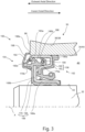
- FIG. 3 illustrates an alternative embodiment of a cassette seal 150 which is similar to the embodiment shown in FIG. 2 and described above. Accordingly, only the major differences of the cassette seal 150 over the cassette seal 50 of the previous embodiment will be described in detail.
- Features of the cassette seal 150 which are the same as, or which serve a similar function to, those of the previous embodiment 50 will be given the same reference numerals but increased by 100 in each case.
- the third radially extending region 160e of the first reinforcing member 160 extends radially inward at the axial outer end of the axially extending region 160a to define a radially extending portion of the stationary member 158 axially outboard of the secondary sealing lips 186a, 186b.
- a first elastomeric sealing member 162 is attached to the first reinforcing member.
- the second reinforcing member 168 of the rotational member 156 is simpler than that of the previous embodiment having only a single axially extending cylindrical region 168a equivalent to the first axially extending cylindrical region 68a in the previous embodiment and a single radially extending region 168b, equivalent to the first radially extending region 68b in the previous embodiment.
- the inner rotational member 156 in this embodiment carries a single elastomeric member 170, referred to as a second elastomeric member to differentiate it from the first elastomeric member 160 of the stationary member 158.
- the second elastomeric member 170 extends axially long the radially inner surface of the axially extending cylindrical region 168a of the second reinforcing member 168 and radially along the axial outer surface of the radially extending portion 168b of the second reinforcing member 168.
- the second elastomeric member 170 extends axially long the radially inner surface of the axially extending cylindrical region 168a of the second reinforcing member 168 it grips the surface 42 of the drive shaft 32 tightly to form a static oil seal with the drive shaft 32 and to hold the rotational member 156 rotationally fast with the drive shaft 32.
- the second elastomeric member 170 defines a first lip portion 170a which extends axially inward beyond the radially extending region 168b of the second reinforcing member and contacts the inclined region 160c of the first reinforcing member 160.
- Two secondary sealing lips 186a, 186b project radially outward and axially outward from the radial outer surface of the first lip portion 170a to engage a radially inner sealing surface 188 of the axially extending cylindrical region 160a of the first reinforcing member 160.
- the two secondary sealing lips 186a, 186b are spaced axially apart and a further spring 190 is operative to bias an axially innermost one of the secondary sealing lips 186a into engagement with the sealing surface 188 and the axially inner end of the first lip portion 170a into engagement with the inclined region 160c of the first reinforcing member 160.
- the axially outermost of the secondary sealing lips 186b in this embodiment also contacts an axially inward directed surface of the third radially extending region 160e of the first reinforcing member 160, which partially encloses the secondary sealing lips 186a, 186b.
- the first lip portion 170a performs a similar function to the axially extending region 84a of the further elastomeric member 84 of the previous embodiment and is constructed in a similar manner.
- the second elastomeric member 168 also defines a second lip portion 170b which projects from the outer radial end of the radially extending region 168b of the second reinforcing member axially outward beyond the third radially extending region 160e of the first reinforcing member 160.
- the second lip portion 170b has an exterior sealing lip 192 which projects radially outward and axially inward such that a distal, free end of the exterior lip 92 engages an axially directed outer face of the third radially extending region 160e of the first reinforcing member 160.
- a cover 198 is attached to the second elastomeric member 170 axially outboard of the exterior sealing lip 192.
- the cover extends radially outward and axially inward to partially enclose the exterior sealing lip 192 and has a free, distal end 198a which locates close to but spaced from an axially directed outer surface 96 of the wall 36 of the housing 38 radially outboard of the aperture 34.
- the cover 198 may be clipped or otherwise attached to the second elastomeric member.
- the cover member 198 is more rigid that the second sealing member 170 and the exterior sealing lip 192 and may also act as a further reinforcing member to support the second lip portion 170b.
- the exterior sealing lip 192 and the cover 198 perform similar functions to those of the previous embodiment shown in FIG. 2 as described above.
- the various seals and sealing lips 186a, 186b, 192 need not be provided by a single integral sealing member 170 attached to the second reinforcing member 168 but could be provided by two or more discrete sealing members attached to the second reinforcing member 168.
- the first and second reinforcing members 60, 68; 160, 168 can be made of any suitable material and by any suitable methods but in an embodiment are made of metallic material and plastically deformed into the required shape.
- the elastomeric sealing members 62, 70, 84; 160, 170 may be securely bonded to the respective reinforcing members in a known manner, for example by cementing or vulcanization.
Landscapes
- Engineering & Computer Science (AREA)
- General Engineering & Computer Science (AREA)
- Mechanical Engineering (AREA)
- Sealing With Elastic Sealing Lips (AREA)
Abstract
Description
- Embodiments of the present disclosure relate generally to a cassette seal for sealing an annular gap between a rotatable shaft and an aperture in a housing through which the shaft passes. Embodiments of the present disclosure relate in particular, but not exclusively, to such a cassette seal for a final drive in an axle of a mobile machine such as a tractor or other agricultural vehicle.
- Cassette seals (also referred to as cartridge seals) are known for sealing between a shaft which in use is rotated about its axis and a surface of an aperture in a housing through which the shaft projects. Often the housing will contain oil and the cassette seal includes oil seals for preventing oil escaping through the aperture about the shaft. This type of known cassette seal has a rotational inner member which is fitted to and rotates with the shaft, and a stationary outer member, which is an interference fit in the aperture of the housing and so remains static. The rotational member typically carries an elastomeric sealing member that forms a static oil seal with the shaft, and the outer member carries another elastomeric sealing member that forms a static oil seal with the surface the housing aperture. The outer member also has an oil sealing lip resiliently biased onto a sealing surface formed on the rotational inner member so as to form a rotary oil seal between stationary and rotational members. In applications where the aperture is in an outer wall of the housing so that the shaft projects externally of the housing through the aperture, and where the cassette seal separates an internal volume of the housing at an axially inner end of the cassette seal from atmosphere at an axially outer end of the cassette seal, it is also known for the inner member to carry secondary or dust sealing lips that engage a sealing surface of the outer member at a position axially outboard of the oil sealing lip. The secondary sealing lips help to prevent dust and other contaminates entering the cassette seal between the stationary and rotational members from reaching the oil sealing lip.
- Aspects of the invention include a cassette seal and a mobile machine having an axle with a final drive incorporating such a cassette seal between a drive shaft and an aperture of a housing of the final drive through which the drive shaft projects.
- According to an aspect of the invention, there is provided a cassette seal for sealing an annular gap between a shaft having a longitudinal axis and mounted for rotation about its longitudinal axis and a surface defining an aperture in a housing through which the shaft projects and for separating an internal volume of the housing at an axially inner end of the cassette seal from atmosphere at an axially outer end of the cassette seal, the cassette seal having an annular rotational member for mounting rotationally fast with the shaft and an annular stationary member for mounting to the surface of the housing defining the aperture, the stationary member comprising a sealing element for forming a static oil seal with the surface of the housing and the rotational member comprising a sealing element for forming a static oil seal with the shaft, the stationary member encircling at least part of the rotational member and having a sealing lip resiliently engaging a sealing surface on the rotational member to form an oil seal between the stationary and rotational members, the rotational member comprising at least one secondary sealing lip engaging a sealing surface of the stationary member at a position axially outboard of the oil sealing lip, the stationary member having a radially extending portion located axially outboard of the at least one secondary sealing lip, wherein the rotational member comprises at least one exterior sealing lip extending radially outward and axially inward to engage an outer surface of the radially extending portion of the outer member.
- In a cassette seal according to this aspect of the invention, the at least one exterior sealing lip may act as a further level of protection in addition to the at least one secondary sealing lip in preventing dust, dirt and other contaminants from entering the cassette seal as far as the oil sealing lip. It is an advantage that any contaminants that do pass the at least one exterior sealing lip can be ejected back past the exterior sealing lip when the inner member is rotated with the shaft due to centrifugal force.
- The rotational member may comprise a cover portion located axially outboard of the at least one exterior sealing lip, the cover portion extending radially outward and axially inward to at least partially enclose the exterior sealing lip, the cover portion being more rigid than the exterior sealing lip.
- The stationary member may comprise a first reinforcing member having an axially extending cylindrical region for engagement with the surface of the housing defining the aperture and a radially extending region at an axial outer end of the axially extending cylindrical region, wherein the radially extending portion of the stationary member may be defined by the radially extending region of the reinforcing member.
- In an embodiment, the radially extending portion of the stationary member extends radially outward, the arrangement configured such that in use, the radially extending portion of the stationary member locates adjacent an outer surface of the housing which surface extends radially about the aperture.
- The rotational member may comprise two of the exterior sealing lips radially spaced apart.
- In an embodiment, the rotational member comprises a second reinforcing member having a first axially extending cylindrical region for location adjacent the shaft and carrying a first elastomeric sealing member which comprises the sealing element for forming a static oil seal with the shaft, the second reinforcing member having a first radially extending region extending radially outward at an axial outer end of the first axially extending cylindrical region, a second axially extending cylindrical region extending axially outward from a radially outer end of the first radially extending region, and a second radially extending region extending radially outward at an axially outer end of the second axially extending cylindrical region, the rotational member having a further elastomeric sealing member attached to the second axially extending cylindrical region and the second radially extending region, the further elastomeric member comprising the at least one secondary sealing lip and the at least one exterior sealing lip.
- In an embodiment, the further elastomeric member comprises an axially extending portion attached to the second axially extending cylindrical region of the second reinforcing member and a radially extending portion attached to the second radially extending region of the second reinforcing member, the at least one secondary lip extending radially outward and axially outward from the axially extending portion of the further elastomeric member and the at least one exterior sealing lip extending radially outward and axially inward from the radially extending portion of the further elastomeric member.
- The cover may comprise a cover region of the second reinforcing member, the cover region extending radially outward and axially inward from a radial outer end of the second radially extending region. A free end of the cover may be located proximal to but spaced from the outer surface of the radially extending portion of the outer member.
- In another embodiment, the radially extending portion of the stationary member extends radially inward.
- In an embodiment, the rotational member comprises a second reinforcing member having an axially extending cylindrical region for location adjacent the shaft and a radially extending region extending radially outward at an outer axial end of the axially extending cylindrical region, the second reinforcing member carrying at least one elastomeric sealing member that defines the sealing element for forming a static oil seal with the shaft, the at least one secondary sealing lip, and the at least one exterior sealing lip.
- In an embodiment, the rotational member comprises a single integral elastomeric sealing member extending along a radially inner surface of the axially extending cylindrical region of the second reinforcing member and an axially outer surface of the radially extending region of the second reinforcing member, the elastomeric sealing member having a first lip portion and a second lip portion, the first lip portion extending axially inward at a radial outer end of the radially extending region of the second reinforcing member, the at least one secondary sealing lip extending radially outward and axially outward from the first lip portion, the second lip portion extending axially outward at the radial outer end of the radially extending region of the second reinforcing member, the at least one exterior sealing lip extending radially outward and axially inward from the second lip portion.
- Where the cassette seal has a cover, the cover may be attached to the at least one elastomeric sealing member and may be clipped to the at least one elastomeric sealing member. The cover may extend radially outboard of the stationary member, the arrangement configured such that in use, a free end of the cover locates proximal to but spaced from an axially directed outer surface of the housing extending radially about the aperture.
- The radially extending region of the first reinforcing member, may at least partially enclose the at least one secondary sealing lip.
- There may be two secondary sealing lips spaced apart axially, and an axial outermost one of the secondary sealing lips may engage an inward directed axial surface of the radially extending region of the first reinforcing member.
- According to an aspect of the invention, there is provided a mobile machine having an axle with a final drive, the final drive including a drive shaft extending through an aperture in a housing of the final drive, wherein a cassette seal according to the previously mentioned aspect of the invention is mounted to seal an annular gap between the drive shaft and a surface defining the aperture in the final drive housing.
- Within the scope of this application it should be understood that the various aspects, embodiments, examples and alternatives set out herein, and individual features thereof may be taken independently or in any possible and compatible combination. Where features are described with reference to a single aspect or embodiment, it should be understood that such features are applicable to all aspects and embodiments unless otherwise stated or where such features are incompatible.
- One or more embodiments of the invention will now be described, by way of example only, with reference to the accompanying drawings, in which:
-
FIG. 1 is view from one side of an agricultural tractor; -
FIG. 2 is a simplified cross-sectional view through part of final drive of the tractor ofFIG. 1 , illustrating a first embodiment of cassette seal in accordance with an aspect of the invention sealing an annular gap (i.e., a radial gap) between a drive shaft and a surface defining an aperture in a housing of the final drive through which the drive shaft extends; and -
FIG. 3 is a view similar to that ofFIG. 2 but illustrating a second embodiment of a cassette seal according to an aspect of the invention. - With reference initially to
FIG. 1 , a mobile machine in the form of anagricultural tractor 10 hasfront wheels 12 mounted to afront axle 14 andrear wheels 16 mounted to arear axle 18. The tractor has achassis 20 and anengine compartment 22 in which an engine or other prime mover is located. Anoperator cab 24 is mounted to thechassis 20 to the rear of theengine compartment 22. - With reference also to
FIG. 2 , at least one of the front andrear axles final drive 30 including at least onedrive shaft 32 extending through an aperture 34 in a wall 36 of a housing 38 of thefinal drive 30. The drive shaft 32 (only an upper portion of an end region of which is shown inFIG. 2 ) is driven to rotate about its longitudinal axis X and is mounted with a clearance orannular gap 40 between its outercylindrical surface 42 and a surface 44 of the housing defining the aperture 34. Theannular gap 40 is shown on an enlarged scale for clarity. - Oil is contained within an
interior volume 46 of the housing and acassette seal 50 according to an aspect of the invention is provided to seal theannular gap 40 between thedrive shaft 32 and the surface 44 of the housing to prevent oil escaping from theinterior volume 46 of the housing. The wall 36 is an exterior wall so that thecassette seal 50 also serves to separate theinterior volume 46 of the housing from atmosphere. Anaxial end 52 of thecassette seal 50 adjacent the interior volume will be referred to as an inner axial end, and anaxial end 54 of the cassette seal which is exposed to atmosphere will be referred to as an outer axial end. - In addition to preventing oil escaping from the
interior volume 46 of the final drive housing 38, thecassette seal 50 is operative to prevent dust and other contaminants from entering theinterior 46 of the housing 38 from the outside. This is particularly important for an agricultural vehicle such as atractor 10 which is often operated in dusty and dirty conditions in fields and the like and where thefinal drive 30 in particular is located close to the ground and so exposed to any dust or other contaminants thrown up by thewheels tractor 10. - The
cassette seal 50 has a radiallyinner member 56 and a radiallyouter member 58. The radiallyinner member 56 is mounted rotationally fast with thedrive shaft 32 so that it rotates with thedrive shaft 32. The inner member will be referred to as arotational member 56. The radiallyouter member 58 is mounted with an interference fit to the surface 44 of the housing and so does not rotate. The radially outer member will be referred to as astationary member 58. Both therotational member 56 and thestationary member 58 are annular. - The
rotational member 56 has an axis of rotation which is coaxial with the longitudinal axis of thedrive shaft 32 when in use. Indeed the axis X can be considered an axis of thecassette seal 50. For the avoidance of doubt, directional terms such as axial, axially, radial or radially and the like as used herein should be understood with reference to the longitudinal axis X of thedrive shaft 32/axis of thecassette seal 50. Thus terms such as axial and axially and the like refer to directions parallel to the longitudinal axis X of the drive shaft/ axis of the cassette seal whilst terms such as radial or radially and the like refer to directions perpendicular to the longitudinal axis X of the drive shaft/axis of thecassette seal 50. - The
stationary member 58 has a reinforcingmember 60, referred to herein as a first reinforcing member. The first reinforcingmember 60 has an axially extendingcylindrical region 60a which is an interference fit to the surface 44 of the housing defining the aperture 34, a first radially extendingregion 60b which extends radially inward at an axial inner end of the axially extendingregion 60a, aninclined region 60c which extends radially inward and axially outward from the inner radial end of the first radially extendingregion 60b. A second radially extendingregion 60d extends radially inward at the radially inner end of theinclined region 60c. A sealing element in the form of a firstelastomeric sealing member 62 is attached to the first reinforcingmember 60. Apart 64 of the firstelastomeric sealing member 62 engages the surface 44 of the housing to form a static oil seal with the surface 44 of the housing. - The
rotational member 56 also has a reinforcingmember 68, referred to herein as a second reinforcing member. The second reinforcingmember 68 has a first axially extendingcylindrical region 68a which locates proximal to thesurface 42 of thedrive shaft 32, a first radially extending portion 68b which extends radially outward towards thestationary member 58 at an axially outer end of the first axially extendingregion 68a, a second axially extendingcylindrical region 68c which extends axially outward from the outer radial end of the first radially extending region 68b, and a secondradially extending region 68d which extends radially outward from an outer axial end of the second axially extending region 68b. - A second elastomeric sealing member 70 is attached to a radially inner surface of the first axially extending
region 68a of the second reinforcingmember 68 and extends along an axial outer surface of the first radially extending region 68b. The second elastomeric sealing member grips thesurface 42 of thedrive shaft 32 tightly to form a static oil seal with thedrive shaft 32 and to hold therotational member 56 rotationally fast with thedrive shaft 32. - The first
elastomeric sealing member 62 defines a sealinglip 72 which is biased by aspring 74 to engage afirst sealing surface 76 defined on a radially inner side of the first axially extendingcylindrical region 68a of the second reinforcingmember 68 to form an oil seal between the rotational andstationary members supplementary sealing lip 78 extends radially inward and axially outward to engage a further sealingsurface 80 defined on a radially inner side of the second reinforcingmember 68. The firstelastomeric sealing member 62 also defines a spacer 82 which engages an axially inner side of the first radially extending region 68b of the second reinforcingmember 68 of therotational member 56 to maintain a desired axial spacing between the rotational andstationary members - A further (i.e., a third) elastomeric sealing
member 84 is attached to the second reinforcingmember 68. The furtherelastomeric sealing member 84 has anaxially extending portion 84a attached to a radially outer face of the second axially extendingcylindrical region 68c. Theaxially extending portion 84a projects axially inward beyond the first radially extending region 68b of the second reinforcing member and contacts theinclined region 60c of the first reinforcingmember 60. Twosecondary sealing lips axially ending portion 84a of the furtherelastomeric sealing member 84 to engage a radiallyinner sealing surface 88 of the axially extendingcylindrical region 60a of the first reinforcingmember 60. The twosecondary sealing lips further spring 90 is operative to bias an axially innermost one of thesecondary sealing lips 86a into engagement with the sealingsurface 88 of the first reinforcing member and the axially inner end of the furtherelastomeric sealing member 84 into engagement with theinclined region 60c of the first reinforcingmember 60. - The further
elastomeric sealing member 84 also has aradially extending portion 84b attached to an axially directed inner surface of the secondradially extending region 68d of the second reinforcingmember 68. Theradially extending portion 84 carries twoexterior sealing lips exterior sealing lips outer surface 94 of a thirdradially extending region 60e of the first reinforcingmember 60. The thirdradially extending region 60e of the first reinforcingmember 60 extends radially outward at an axial outer end of the axially extendingcylindrical region 60a of the first reinforcingmember 60 and defines a radially extending portion of thestationary member 58 located axially outboard of thesecondary sealing lips radially extending region 60e projects radially outside the aperture 34 and an axially inward directed surface of the thirdradially extending region 60e is arranged to abut, or at least to lie in close proximity to, an axially outward directedsurface 96 of the housing which surface extends radially outboard of the aperture. - The
exterior sealing lips member 68 which extends radially outward and axially inward from the outer radial end of the secondradially extending region 68d of the second reinforcingmember 68. A distal,free end 98a of the cover locates close to but slightly spaced from theouter surface 94 of the thirdradially extending region 60e of the first reinforcingmember 60. - The
secondary sealing lips cassette seal 50 from outside from passing through to theoil sealing lip 72. However, particularly when used in heavily contaminated environments, such as is the case for a final drive of a tractor operating in a field, they may not be wholly effective. A particular issue is that dust and dirt entering the cassette seal can become trapped in thecassette seal 50 by thesecondary sealing lips exterior sealing lips cassette seal 50. Furthermore, because theexterior sealing lips outer surface 94 of the thirdradially extending region 60e of the first reinforcingmember 60 outside of the aperture 34, should any dust, dirt or other contaminants enter thecassette seal 50 past theexterior sealing lips secondary sealing lips cassette seal 50 back past theexterior sealing lips rotational member 56 is rotated with thedrive shaft 32. Removing such contaminants reduces the risk of their damaging thecassette seal 50. - The cover 98 is more rigid than the
exterior sealing lips final drive 30 of a tractor using a pressure washer, the cover 98 helps to protect theexterior sealing lips exterior sealing lips - Though the embodiment of
FIG. 2 has twoexterior sealing lips cassette seal 50 may have only one exterior sealing lip or may have three or moreexterior sealing lips cassette seal 50 may have only onesecondary sealing lip integral elastomeric member 84 attached to the second reinforcingmember 68 simplifies manufacturing, the sealinglips member 68. -
FIG. 3 illustrates an alternative embodiment of acassette seal 150 which is similar to the embodiment shown inFIG. 2 and described above. Accordingly, only the major differences of thecassette seal 150 over thecassette seal 50 of the previous embodiment will be described in detail. Features of thecassette seal 150 which are the same as, or which serve a similar function to, those of theprevious embodiment 50 will be given the same reference numerals but increased by 100 in each case. - In the
cassette seal 150 according to the second embodiment, the thirdradially extending region 160e of the first reinforcingmember 160 extends radially inward at the axial outer end of theaxially extending region 160a to define a radially extending portion of thestationary member 158 axially outboard of thesecondary sealing lips elastomeric sealing member 162 is attached to the first reinforcing member. - The second reinforcing
member 168 of therotational member 156 is simpler than that of the previous embodiment having only a single axially extendingcylindrical region 168a equivalent to the first axially extendingcylindrical region 68a in the previous embodiment and a singleradially extending region 168b, equivalent to the first radially extending region 68b in the previous embodiment. - The inner
rotational member 156 in this embodiment carries a singleelastomeric member 170, referred to as a second elastomeric member to differentiate it from the firstelastomeric member 160 of thestationary member 158. The secondelastomeric member 170 extends axially long the radially inner surface of the axially extendingcylindrical region 168a of the second reinforcingmember 168 and radially along the axial outer surface of theradially extending portion 168b of the second reinforcingmember 168. Where the secondelastomeric member 170 extends axially long the radially inner surface of the axially extendingcylindrical region 168a of the second reinforcingmember 168 it grips thesurface 42 of thedrive shaft 32 tightly to form a static oil seal with thedrive shaft 32 and to hold therotational member 156 rotationally fast with thedrive shaft 32. - At the radially outer end of the
radially extending region 168b of the second reinforcingmember 168, the secondelastomeric member 170 defines afirst lip portion 170a which extends axially inward beyond theradially extending region 168b of the second reinforcing member and contacts the inclined region 160c of the first reinforcingmember 160. Twosecondary sealing lips first lip portion 170a to engage a radiallyinner sealing surface 188 of the axially extendingcylindrical region 160a of the first reinforcingmember 160. The twosecondary sealing lips further spring 190 is operative to bias an axially innermost one of thesecondary sealing lips 186a into engagement with the sealingsurface 188 and the axially inner end of thefirst lip portion 170a into engagement with the inclined region 160c of the first reinforcingmember 160. The axially outermost of thesecondary sealing lips 186b in this embodiment also contacts an axially inward directed surface of the thirdradially extending region 160e of the first reinforcingmember 160, which partially encloses thesecondary sealing lips first lip portion 170a performs a similar function to theaxially extending region 84a of the furtherelastomeric member 84 of the previous embodiment and is constructed in a similar manner. - The second
elastomeric member 168 also defines asecond lip portion 170b which projects from the outer radial end of theradially extending region 168b of the second reinforcing member axially outward beyond the thirdradially extending region 160e of the first reinforcingmember 160. Thesecond lip portion 170b has anexterior sealing lip 192 which projects radially outward and axially inward such that a distal, free end of the exterior lip 92 engages an axially directed outer face of the thirdradially extending region 160e of the first reinforcingmember 160. - A
cover 198 is attached to the secondelastomeric member 170 axially outboard of theexterior sealing lip 192. The cover extends radially outward and axially inward to partially enclose theexterior sealing lip 192 and has a free,distal end 198a which locates close to but spaced from an axially directedouter surface 96 of the wall 36 of the housing 38 radially outboard of the aperture 34. Thecover 198 may be clipped or otherwise attached to the second elastomeric member. Thecover member 198 is more rigid that thesecond sealing member 170 and theexterior sealing lip 192 and may also act as a further reinforcing member to support thesecond lip portion 170b. - The
exterior sealing lip 192 and thecover 198 perform similar functions to those of the previous embodiment shown inFIG. 2 as described above. - In alternative embodiments, there may be more than one exterior sealing lip 92 and may be more or fewer than two
secondary sealing lips lips integral sealing member 170 attached to the second reinforcingmember 168 but could be provided by two or more discrete sealing members attached to the second reinforcingmember 168. - The first and second reinforcing
members elastomeric sealing members
Claims (15)
- A cassette seal (50; 150) for sealing an annular gap (40) between a shaft (32) having a longitudinal axis (X) and mounted for rotation about its longitudinal axis and a surface (44) defining an aperture (34) in a housing (38) through which the shaft projects and for separating an internal volume (46) of the housing at an axially inner end (52; 152) of the cassette seal from atmosphere at an axially outer end (54; 154) of the cassette seal, the cassette seal having an annular rotational member (56; 156) for mounting rotationally fast with the shaft and an annular stationary member (58; 158) for mounting to the surface of the housing defining the aperture, the stationary member comprising a sealing element (64) for forming a static oil seal with the surface of the housing and the rotational member comprising a sealing element (70; 170) for forming a static oil seal with the shaft, the stationary member encircling at least part of the rotational member and having a sealing lip (72) configured to resiliently engage a sealing surface (76) on the rotational member to form an oil seal between the stationary and rotational members, the rotational member comprising at least one secondary sealing lip (86a, 86b; 186a, 186b) configured to engage a sealing surface (88; 188) of the stationary member at a position axially outboard of the oil sealing lip, the stationary member having a radially extending portion (60e; 160e) located axially outboard of the at least one secondary sealing lip, wherein the rotational member comprises at least one exterior sealing lip (92a, 92b; 192) extending radially outward and axially inward to engage an outer surface (94) of the radially extending portion of the stationary member.
- A cassette seal (50; 150) according to claim 1, wherein the rotational member comprises a cover portion (98; 198) located axially outboard of the at least one exterior sealing lip (92a, 92b; 192), the cover portion extending radially outward and axially inward to at least partially enclose the exterior sealing lip (92a, 92b; 192), the cover portion being more rigid than the exterior sealing lip.
- A cassette seal (50; 150) according to claim 1 or claim 2, wherein the stationary member comprises a first reinforcing member (60; 160), the first reinforcing member comprising an axially extending cylindrical region (60a; 160a) for engagement with the surface of the housing defining the aperture and a radially extending region (60e; 160e) at an axial outer end of the axially extending cylindrical region, and wherein the radially extending portion of the stationary member is defined by the radially extending region of the reinforcing member.
- A cassette seal (50) according to any one of claims 1 to 3, wherein the radially extending portion (60e) of the stationary member extends radially outward, the arrangement configured such that in use, the radially extending portion of the stationary member locates adjacent an outer surface (96) of the housing extending radially about the aperture (34).
- A cassette seal (50) according to claim 4, wherein the rotational member (56) comprises two of the exterior sealing lips (92a, 92b) radially spaced apart.
- A cassette seal (50) according to claim 4 or claim 5, wherein the rotational member (56) comprises a second reinforcing member (68) having a first axially extending cylindrical region (68a) for location adjacent the shaft (32) and carrying a first elastomeric sealing member (70) which comprises the sealing element for forming a static oil seal with the shaft, the second reinforcing member having a first radially extending region (68b) extending radially outward at an axial outer end of the first axially extending cylindrical region, a second axially extending cylindrical region (68c) extending axially outward from a radially outer end of the first radially extending region, and a second radially extending region (68d) extending radially outward at an axially outer end of the second axially extending region, the rotational member having a further elastomeric sealing member (84) attached to the second axially extending cylindrical region and the second radially extending region, the further elastomeric member comprising the at least one secondary sealing lip (86a, 86b) and the at least one exterior sealing lip (92a, 92b).
- A cassette seal (50) according to claim 6, wherein the further elastomeric member (84) comprises an axially extending portion (84a) attached to the second axially extending cylindrical region (68c) of the second reinforcing member and a radially extending portion (84b) attached to the second radially extending region (68d) of the second reinforcing member, the at least one secondary lip (86a, 86b) extending radially outward and axially outward from the axially extending portion (84a) of the further elastomeric member and the at least one exterior sealing lip (92a, 92b) extending radially outward and axially inward from the radially extending portion (84b) of the further elastomeric member.
- A cassette seal (50) according to claim 6 or claim 7, both when dependent on claim 2, wherein the cover (98) comprises a cover region (68e) of the second reinforcing member (68), the cover region extending radially outward and axially inward from a radial outer end of the second radially extending region (68d).
- A cassette seal (50) according to any one of claims 4 to 8, each when dependent on claim 2, wherein a free end (98a) of the cover (98) is located proximal to but spaced from the outer surface (94) of the radially extending portion (60e) of the stationary member.
- A cassette seal (150) according to any one of claims 1 to 3, wherein the radially extending portion (160e) of the stationary member (158) extends radially inward.
- A cassette seal (150) according to claim 10, wherein the rotational member (156) comprises a second reinforcing member (168) having an axially extending cylindrical region (168a) for location adjacent the shaft and a radially extending region (168b) extending radially outward at an outer axial end of the axially extending cylindrical region, the second reinforcing member carrying at least one elastomeric sealing member (170) which defines the sealing element for forming a static oil seal with the shaft, the at least one secondary sealing lip (186a, 186b), and the at least one exterior sealing lip (192).
- A cassette seal (150) according to claim 11, wherein the rotational member (156) comprises a single integral elastomeric sealing member (170) extending along a radially inner surface of the axially extending cylindrical region (168a) of the second reinforcing member and an axially outer surface of the radially extending region (168b) of the second reinforcing member, the elastomeric sealing member having a first lip portion (170a) and a second lip portion (170b), the first lip portion (170a) extending axially inward at a radial outer end of the radially extending region (168a) of the second reinforcing member, the at least one secondary sealing lip (186a, 186b) extending radially outward and axially outward from the first lip portion, the second lip portion (170b) extending axially outward at the radial outer end of the radially extending region (168b) of the second reinforcing member, the at least one exterior sealing lip (192) extending radially outward and axially inward from the second lip portion.
- A cassette seal (150) according to either of claim 11 or claim 12, each when dependent on claim 2, wherein the cover (198) is attached to the at least one elastomeric sealing member (170) and wherein, optionally, the cover is clipped to the at least one elastomeric sealing member.
- A cassette seal (150) according to any one of claims 10 to 13, each when dependent on claim 2, wherein the cover (198) extends radially outboard of the stationary member, the arrangement configured such that in use, a free end (198a) of the cover locates proximal to but spaced from an axially directed outer surface (96) of the housing extending radially about the aperture.
- A mobile machine (10) having an axle with a final drive, the final drive including a drive shaft (32) extending through an aperture (34) in a housing (38) of the final drive, wherein a cassette seal (50; 150) according to any one of the preceding claims is mounted to seal an annular gap (40) between the drive shaft (32) and a surface (44) defining the aperture in the final drive housing.
Applications Claiming Priority (1)
| Application Number | Priority Date | Filing Date | Title |
|---|---|---|---|
| GBGB2216964.3A GB202216964D0 (en) | 2022-11-14 | 2022-11-14 | Cassette seal |
Publications (2)
| Publication Number | Publication Date |
|---|---|
| EP4368860A1 true EP4368860A1 (en) | 2024-05-15 |
| EP4368860B1 EP4368860B1 (en) | 2026-04-22 |
Family
ID=84839975
Family Applications (1)
| Application Number | Title | Priority Date | Filing Date |
|---|---|---|---|
| EP23197649.9A Active EP4368860B1 (en) | 2022-11-14 | 2023-09-15 | Cassette seal |
Country Status (3)
| Country | Link |
|---|---|
| US (1) | US12510160B2 (en) |
| EP (1) | EP4368860B1 (en) |
| GB (1) | GB202216964D0 (en) |
Citations (3)
| Publication number | Priority date | Publication date | Assignee | Title |
|---|---|---|---|---|
| JP2007292192A (en) * | 2006-04-25 | 2007-11-08 | Nok Corp | Sealing deice |
| JP2012087814A (en) * | 2010-10-15 | 2012-05-10 | Nok Corp | Hermetically sealing device |
| EP3078886A1 (en) * | 2015-04-07 | 2016-10-12 | Freudenberg Sealing Technologies S.A.S Di Externa Italia S.R.L.U | A gasket |
Family Cites Families (12)
| Publication number | Priority date | Publication date | Assignee | Title |
|---|---|---|---|---|
| FR2630179B1 (en) | 1988-04-14 | 1991-03-29 | Procal | CARTRIDGE SEAL |
| DE3940003A1 (en) * | 1989-12-02 | 1991-06-06 | Freudenberg Carl Fa | CASSETTE SEAL |
| US5201529A (en) * | 1990-02-16 | 1993-04-13 | Nok Corporation | Sealing device |
| US5183269A (en) * | 1991-02-06 | 1993-02-02 | Chicago Rawhide Manufacturing Co. | Unitized grit seal with removable thrust bumper |
| JP3885396B2 (en) | 1998-12-24 | 2007-02-21 | Nok株式会社 | Sealing device |
| DE102005006445A1 (en) * | 2005-02-12 | 2006-08-24 | Gkn Driveline International Gmbh | Sealing unit, for connection between stationary rubber sleeve and rotating shaft, comprising contactless as well as sliding elements |
| US8016293B2 (en) * | 2006-01-03 | 2011-09-13 | Freudenberg-Nok General Partnership | Contaminant exclusion seal |
| JP5003862B2 (en) | 2006-03-31 | 2012-08-15 | Nok株式会社 | Sealing device |
| DE102007057962B4 (en) * | 2007-12-01 | 2022-04-14 | Schaeffler Technologies AG & Co. KG | Cassette seal and wheel bearing with the cassette seal |
| JP5158389B2 (en) * | 2008-11-28 | 2013-03-06 | Nok株式会社 | Sealing device |
| DE102017204857A1 (en) | 2017-03-22 | 2018-09-27 | Zf Friedrichshafen Ag | seal means |
| JP2022051326A (en) * | 2020-09-18 | 2022-03-31 | Ntn株式会社 | Bearing device for wheel |
-
2022
- 2022-11-14 GB GBGB2216964.3A patent/GB202216964D0/en not_active Ceased
-
2023
- 2023-09-15 EP EP23197649.9A patent/EP4368860B1/en active Active
- 2023-10-09 US US18/482,950 patent/US12510160B2/en active Active
Patent Citations (3)
| Publication number | Priority date | Publication date | Assignee | Title |
|---|---|---|---|---|
| JP2007292192A (en) * | 2006-04-25 | 2007-11-08 | Nok Corp | Sealing deice |
| JP2012087814A (en) * | 2010-10-15 | 2012-05-10 | Nok Corp | Hermetically sealing device |
| EP3078886A1 (en) * | 2015-04-07 | 2016-10-12 | Freudenberg Sealing Technologies S.A.S Di Externa Italia S.R.L.U | A gasket |
Also Published As
| Publication number | Publication date |
|---|---|
| GB202216964D0 (en) | 2022-12-28 |
| EP4368860B1 (en) | 2026-04-22 |
| US12510160B2 (en) | 2025-12-30 |
| US20240159316A1 (en) | 2024-05-16 |
Similar Documents
| Publication | Publication Date | Title |
|---|---|---|
| US5611548A (en) | Sealing arrangement | |
| EP1783405A1 (en) | Sealing device | |
| US6357757B1 (en) | Integral seal protector/labyrinth | |
| KR890004033B1 (en) | Radial oil sealing | |
| US6257587B1 (en) | Radial lip seal having protected porous dust excluder | |
| CN110088492B (en) | Sealing means | |
| CN112469911A (en) | Sealing member and wheel bearing device provided with sealing member | |
| JPH0694903B2 (en) | Cassette packing | |
| EP4368860B1 (en) | Cassette seal | |
| US6027122A (en) | Sealing assembly for a rolling element bearing | |
| CN108412905B (en) | Universal joint bearing | |
| JP7624104B2 (en) | Propeller shaft | |
| KR101980881B1 (en) | Differential side oil seal | |
| US6311985B1 (en) | Integral yoke and slinger | |
| KR101705874B1 (en) | Differential side oil seal | |
| JP2005282711A (en) | Dust-proof connecting structure of rotary shaft | |
| CN108691993B (en) | Seal assembly for steering gear input shaft | |
| US7086952B2 (en) | Propshaft boot with integrated bearing seal deflector and clampless retention | |
| JP2017219176A (en) | Axle seal device for agricultural machine and seal member | |
| JP3764262B2 (en) | Bearing device | |
| JP4857514B2 (en) | Sealing device | |
| JP6839948B2 (en) | Axle sealing device for agricultural machinery | |
| JP2016200259A (en) | Sealing device | |
| KR101699942B1 (en) | Differential side oil seal | |
| JP3359462B2 (en) | Sealing device |
Legal Events
| Date | Code | Title | Description |
|---|---|---|---|
| PUAI | Public reference made under article 153(3) epc to a published international application that has entered the european phase |
Free format text: ORIGINAL CODE: 0009012 |
|
| STAA | Information on the status of an ep patent application or granted ep patent |
Free format text: STATUS: THE APPLICATION HAS BEEN PUBLISHED |
|
| AK | Designated contracting states |
Kind code of ref document: A1 Designated state(s): AL AT BE BG CH CY CZ DE DK EE ES FI FR GB GR HR HU IE IS IT LI LT LU LV MC ME MK MT NL NO PL PT RO RS SE SI SK SM TR |
|
| STAA | Information on the status of an ep patent application or granted ep patent |
Free format text: STATUS: REQUEST FOR EXAMINATION WAS MADE |
|
| 17P | Request for examination filed |
Effective date: 20241115 |
|
| RBV | Designated contracting states (corrected) |
Designated state(s): AL AT BE BG CH CY CZ DE DK EE ES FI FR GB GR HR HU IE IS IT LI LT LU LV MC ME MK MT NL NO PL PT RO RS SE SI SK SM TR |
|
| STAA | Information on the status of an ep patent application or granted ep patent |
Free format text: STATUS: EXAMINATION IS IN PROGRESS |
|
| 17Q | First examination report despatched |
Effective date: 20250508 |
|
| GRAP | Despatch of communication of intention to grant a patent |
Free format text: ORIGINAL CODE: EPIDOSNIGR1 |
|
| STAA | Information on the status of an ep patent application or granted ep patent |
Free format text: STATUS: GRANT OF PATENT IS INTENDED |
|
| INTG | Intention to grant announced |
Effective date: 20251127 |
|
| GRAS | Grant fee paid |
Free format text: ORIGINAL CODE: EPIDOSNIGR3 |
|
| GRAA | (expected) grant |
Free format text: ORIGINAL CODE: 0009210 |
|
| STAA | Information on the status of an ep patent application or granted ep patent |
Free format text: STATUS: THE PATENT HAS BEEN GRANTED |
|
| AK | Designated contracting states |
Kind code of ref document: B1 Designated state(s): AL AT BE BG CH CY CZ DE DK EE ES FI FR GB GR HR HU IE IS IT LI LT LU LV MC ME MK MT NL NO PL PT RO RS SE SI SK SM TR |
|
| REG | Reference to a national code |
Ref country code: CH Ref legal event code: F10 Free format text: ST27 STATUS EVENT CODE: U-0-0-F10-F00 (AS PROVIDED BY THE NATIONAL OFFICE) Effective date: 20260422 Ref country code: GB Ref legal event code: FG4D |
|
| REG | Reference to a national code |
Ref country code: DE Ref legal event code: R096 Ref document number: 602023015621 Country of ref document: DE |