EP4368566A1 - Hydrogen compression system - Google Patents
Hydrogen compression system Download PDFInfo
- Publication number
- EP4368566A1 EP4368566A1 EP23179161.7A EP23179161A EP4368566A1 EP 4368566 A1 EP4368566 A1 EP 4368566A1 EP 23179161 A EP23179161 A EP 23179161A EP 4368566 A1 EP4368566 A1 EP 4368566A1
- Authority
- EP
- European Patent Office
- Prior art keywords
- hydrogen
- compression part
- metal hydride
- circulation line
- line
- Prior art date
- Legal status (The legal status is an assumption and is not a legal conclusion. Google has not performed a legal analysis and makes no representation as to the accuracy of the status listed.)
- Pending
Links
Images

Classifications
-
- F—MECHANICAL ENGINEERING; LIGHTING; HEATING; WEAPONS; BLASTING
- F25—REFRIGERATION OR COOLING; COMBINED HEATING AND REFRIGERATION SYSTEMS; HEAT PUMP SYSTEMS; MANUFACTURE OR STORAGE OF ICE; LIQUEFACTION SOLIDIFICATION OF GASES
- F25B—REFRIGERATION MACHINES, PLANTS OR SYSTEMS; COMBINED HEATING AND REFRIGERATION SYSTEMS; HEAT PUMP SYSTEMS
- F25B1/00—Compression machines, plants or systems with non-reversible cycle
- F25B1/10—Compression machines, plants or systems with non-reversible cycle with multi-stage compression
-
- C—CHEMISTRY; METALLURGY
- C01—INORGANIC CHEMISTRY
- C01B—NON-METALLIC ELEMENTS; COMPOUNDS THEREOF; METALLOIDS OR COMPOUNDS THEREOF NOT COVERED BY SUBCLASS C01C
- C01B3/00—Hydrogen; Gaseous mixtures containing hydrogen; Separation of hydrogen from mixtures containing it; Purification of hydrogen; Reversible storage of hydrogen
- C01B3/0005—Reversible storage of hydrogen, e.g. by hydrogen getters or electrodes
-
- F—MECHANICAL ENGINEERING; LIGHTING; HEATING; WEAPONS; BLASTING
- F25—REFRIGERATION OR COOLING; COMBINED HEATING AND REFRIGERATION SYSTEMS; HEAT PUMP SYSTEMS; MANUFACTURE OR STORAGE OF ICE; LIQUEFACTION SOLIDIFICATION OF GASES
- F25B—REFRIGERATION MACHINES, PLANTS OR SYSTEMS; COMBINED HEATING AND REFRIGERATION SYSTEMS; HEAT PUMP SYSTEMS
- F25B29/00—Combined heating and refrigeration systems, e.g. operating alternately or simultaneously
- F25B29/003—Combined heating and refrigeration systems, e.g. operating alternately or simultaneously of the compression type system
-
- B—PERFORMING OPERATIONS; TRANSPORTING
- B01—PHYSICAL OR CHEMICAL PROCESSES OR APPARATUS IN GENERAL
- B01D—SEPARATION
- B01D3/00—Distillation or related exchange processes in which liquids are contacted with gaseous media, e.g. stripping
- B01D3/007—Energy recuperation; Heat pumps
-
- C—CHEMISTRY; METALLURGY
- C01—INORGANIC CHEMISTRY
- C01B—NON-METALLIC ELEMENTS; COMPOUNDS THEREOF; METALLOIDS OR COMPOUNDS THEREOF NOT COVERED BY SUBCLASS C01C
- C01B3/00—Hydrogen; Gaseous mixtures containing hydrogen; Separation of hydrogen from mixtures containing it; Purification of hydrogen; Reversible storage of hydrogen
- C01B3/0005—Reversible storage of hydrogen, e.g. by hydrogen getters or electrodes
- C01B3/001—Reversible storage of hydrogen, e.g. by hydrogen getters or electrodes characterised by the uptaking media; Treatment thereof
-
- C—CHEMISTRY; METALLURGY
- C01—INORGANIC CHEMISTRY
- C01B—NON-METALLIC ELEMENTS; COMPOUNDS THEREOF; METALLOIDS OR COMPOUNDS THEREOF NOT COVERED BY SUBCLASS C01C
- C01B3/00—Hydrogen; Gaseous mixtures containing hydrogen; Separation of hydrogen from mixtures containing it; Purification of hydrogen; Reversible storage of hydrogen
- C01B3/0005—Reversible storage of hydrogen, e.g. by hydrogen getters or electrodes
- C01B3/001—Reversible storage of hydrogen, e.g. by hydrogen getters or electrodes characterised by the uptaking media; Treatment thereof
- C01B3/0018—Inorganic elements or compounds, e.g. oxides, nitrides, borohydrides or zeolites; Solutions thereof
- C01B3/0031—Intermetallic compounds; Metal alloys
-
- C—CHEMISTRY; METALLURGY
- C01—INORGANIC CHEMISTRY
- C01B—NON-METALLIC ELEMENTS; COMPOUNDS THEREOF; METALLOIDS OR COMPOUNDS THEREOF NOT COVERED BY SUBCLASS C01C
- C01B3/00—Hydrogen; Gaseous mixtures containing hydrogen; Separation of hydrogen from mixtures containing it; Purification of hydrogen; Reversible storage of hydrogen
- C01B3/0005—Reversible storage of hydrogen, e.g. by hydrogen getters or electrodes
- C01B3/001—Reversible storage of hydrogen, e.g. by hydrogen getters or electrodes characterised by the uptaking media; Treatment thereof
- C01B3/0018—Inorganic elements or compounds, e.g. oxides, nitrides, borohydrides or zeolites; Solutions thereof
- C01B3/0031—Intermetallic compounds; Metal alloys
- C01B3/0047—Intermetallic compounds; Metal alloys containing a rare earth metal
- C01B3/0057—Intermetallic compounds; Metal alloys containing a rare earth metal and nickel
-
- F—MECHANICAL ENGINEERING; LIGHTING; HEATING; WEAPONS; BLASTING
- F17—STORING OR DISTRIBUTING GASES OR LIQUIDS
- F17C—VESSELS FOR CONTAINING OR STORING COMPRESSED, LIQUEFIED OR SOLIDIFIED GASES; FIXED-CAPACITY GAS-HOLDERS; FILLING VESSELS WITH, OR DISCHARGING FROM VESSELS, COMPRESSED, LIQUEFIED, OR SOLIDIFIED GASES
- F17C11/00—Use of gas-solvents or gas-sorbents in vessels
- F17C11/005—Use of gas-solvents or gas-sorbents in vessels for hydrogen
-
- F—MECHANICAL ENGINEERING; LIGHTING; HEATING; WEAPONS; BLASTING
- F25—REFRIGERATION OR COOLING; COMBINED HEATING AND REFRIGERATION SYSTEMS; HEAT PUMP SYSTEMS; MANUFACTURE OR STORAGE OF ICE; LIQUEFACTION SOLIDIFICATION OF GASES
- F25B—REFRIGERATION MACHINES, PLANTS OR SYSTEMS; COMBINED HEATING AND REFRIGERATION SYSTEMS; HEAT PUMP SYSTEMS
- F25B41/00—Fluid-circulation arrangements
- F25B41/20—Disposition of valves, e.g. of on-off valves or flow control valves
-
- F—MECHANICAL ENGINEERING; LIGHTING; HEATING; WEAPONS; BLASTING
- F25—REFRIGERATION OR COOLING; COMBINED HEATING AND REFRIGERATION SYSTEMS; HEAT PUMP SYSTEMS; MANUFACTURE OR STORAGE OF ICE; LIQUEFACTION SOLIDIFICATION OF GASES
- F25B—REFRIGERATION MACHINES, PLANTS OR SYSTEMS; COMBINED HEATING AND REFRIGERATION SYSTEMS; HEAT PUMP SYSTEMS
- F25B41/00—Fluid-circulation arrangements
- F25B41/40—Fluid line arrangements
-
- F—MECHANICAL ENGINEERING; LIGHTING; HEATING; WEAPONS; BLASTING
- F25—REFRIGERATION OR COOLING; COMBINED HEATING AND REFRIGERATION SYSTEMS; HEAT PUMP SYSTEMS; MANUFACTURE OR STORAGE OF ICE; LIQUEFACTION SOLIDIFICATION OF GASES
- F25B—REFRIGERATION MACHINES, PLANTS OR SYSTEMS; COMBINED HEATING AND REFRIGERATION SYSTEMS; HEAT PUMP SYSTEMS
- F25B41/00—Fluid-circulation arrangements
- F25B41/40—Fluid line arrangements
- F25B41/42—Arrangements for diverging or converging flows, e.g. branch lines or junctions
-
- F—MECHANICAL ENGINEERING; LIGHTING; HEATING; WEAPONS; BLASTING
- F25—REFRIGERATION OR COOLING; COMBINED HEATING AND REFRIGERATION SYSTEMS; HEAT PUMP SYSTEMS; MANUFACTURE OR STORAGE OF ICE; LIQUEFACTION SOLIDIFICATION OF GASES
- F25B—REFRIGERATION MACHINES, PLANTS OR SYSTEMS; COMBINED HEATING AND REFRIGERATION SYSTEMS; HEAT PUMP SYSTEMS
- F25B2400/00—Component parts or details not otherwise provided for in this subclass
- F25B2400/01—Heaters
-
- F—MECHANICAL ENGINEERING; LIGHTING; HEATING; WEAPONS; BLASTING
- F25—REFRIGERATION OR COOLING; COMBINED HEATING AND REFRIGERATION SYSTEMS; HEAT PUMP SYSTEMS; MANUFACTURE OR STORAGE OF ICE; LIQUEFACTION SOLIDIFICATION OF GASES
- F25B—REFRIGERATION MACHINES, PLANTS OR SYSTEMS; COMBINED HEATING AND REFRIGERATION SYSTEMS; HEAT PUMP SYSTEMS
- F25B2400/00—Component parts or details not otherwise provided for in this subclass
- F25B2400/04—Refrigeration circuit bypassing means
- F25B2400/0401—Refrigeration circuit bypassing means for compressors
-
- F—MECHANICAL ENGINEERING; LIGHTING; HEATING; WEAPONS; BLASTING
- F25—REFRIGERATION OR COOLING; COMBINED HEATING AND REFRIGERATION SYSTEMS; HEAT PUMP SYSTEMS; MANUFACTURE OR STORAGE OF ICE; LIQUEFACTION SOLIDIFICATION OF GASES
- F25B—REFRIGERATION MACHINES, PLANTS OR SYSTEMS; COMBINED HEATING AND REFRIGERATION SYSTEMS; HEAT PUMP SYSTEMS
- F25B2400/00—Component parts or details not otherwise provided for in this subclass
- F25B2400/07—Details of compressors or related parts
- F25B2400/075—Details of compressors or related parts with parallel compressors
Definitions
- Embodiments of the present disclosure relate to a hydrogen compression system, and more particularly, to a hydrogen compression system capable of minimizing electric power consumption and improving energy efficiency when compressing hydrogen by using a thermochemical method.
- Hydrogen may be produced by hydrogen production facilities using steam reforming, water electrolysis, coal gasification, biomass gasification, and other fossil fuel-based methods such as a thermochemical process.
- hydrogen extracted (produced) in the hydrogen production facility has a low pressure (e.g., 10 bar or less), it is difficult to store the hydrogen directly in a high-pressure storage facility such as a high-pressure tank. Therefore, hydrogen extracted (produced) in the hydrogen production facility needs to be compressed by a separate compression facility.
- Examples of a method of compressing hydrogen include a method of compressing hydrogen in a mechanical manner and a method of compressing hydrogen in a non-mechanical manner.
- a thermochemical compressor based on metal hydride namely, a metal hydride-based thermochemical compressor
- thermochemical compressor may compress hydrogen without a separate mechanical component (e.g., a piston configured to reciprocate). Therefore, it is possible to simplify the structure of the compressor and improve a degree of design freedom and spatial utilization. Further, the thermochemical compressor may cause less noise and be easily maintained and repaired because the cycle for replacing various types of components abraded by rotating devices is long. In addition, the mechanical compressor often contaminates hydrogen because the mechanical compressor uses lubricating oil. In contrast, the thermochemical hydrogen compressor releases hydrogen by breaking chemical bonds in the form of metal hydride without the use of lubricating oil, which makes it possible to maintain high-purity hydrogen.
- the thermochemical compressor may compress hydrogen through a process of repeatedly heating and cooling a metal hydride material by using characteristics of the metal hydride material.
- An equilibrium pressure of a reaction for making metal hydride by storing hydrogen in metal varies depending on the composition and temperature of the material. In general, the equilibrium pressure increases as the temperature increases. Therefore, when hydrogen, which is introduced at a low temperature and a low pressure, forms metal hydride, the temperature is increased and then hydrogen is compressed through a process in which high-pressure hydrogen is released from metal hydride.
- a separate electric heat source e.g., an electric heater
- the metal hydride material needs to be heated by heat transferred from the electric heat source to the metal hydride material by conduction. For this reason, there is a problem in that electric power consumption increases and energy efficiency decreases.
- the present disclosure has been made in an effort to provide a hydrogen compression system capable of minimizing electric power consumption and improving energy efficiency when compressing hydrogen by using a thermochemical method.
- the present disclosure has been made in an effort to operate a metal hydride compressor by using a refrigerant of a heat pump part as a heat source.
- the present disclosure has also been made in an effort to continuously extract high-pressure hydrogen.
- the hydrogen compression system includes: a heat pump part including a heat pump line configured to allow a refrigerant to circulate therethrough; a hydrogen compression part configured to compress hydrogen by being repeatedly heated and cooled; and a first circulation line connected to the heat pump line while passing through the hydrogen compression part and configured to allow the refrigerant introduced from the heat pump line to circulate therethrough.
- the hydrogen compression system further includes: a second circulation line provided to pass through the hydrogen compression part and configured to allow a cooling fluid to circulate therethrough; and a cooling unit provided in the second circulation line and configured to cool the cooling fluid, in which the hydrogen compression part is heated by the refrigerant or cooled by the cooling fluid.
- thermochemical method to compress hydrogen by using the thermochemical method, a separate electric heat source (e.g., an electric heater) for heating the metal hydride material needs to be provided, and the metal hydride material needs to be heated by heat transferred from the electric heat source to the metal hydride material by conduction. For this reason, there is a problem in that electric power consumption increases and energy efficiency decreases.
- an electric heat source e.g., an electric heater
- the hydrogen compression part configured to compress hydrogen by using a thermochemical method may be heated or cooled by the refrigerant and the cooling fluid of the heat pump part, such that the hydrogen compression part may be operated (heated and cooled) to compress hydrogen even without using a separate electric heat source (e.g., an electric heater) that consumes a large amount of electric power. Therefore, it is possible to obtain an advantageous effect of minimizing electric power consumption and remarkably improving energy efficiency (for example, by 50%) in comparison with a method that heats a hydrogen compression part by using an electric heat source.
- a separate electric heat source e.g., an electric heater
- the heat pump part may have various structures capable of converting thermal energy of a low-temperature object (e.g., the refrigerant) into high-temperature thermal energy by supplying mechanical energy from the outside.
- a low-temperature object e.g., the refrigerant
- the heat pump part may include: a compressor provided in the heat pump line and configured to compress the refrigerant; a condenser provided in the heat pump line and configured to condense the refrigerant; an expansion valve provided in the heat pump line and configured to decompress the refrigerant; and an evaporator provided in the heat pump line and configured to vaporize the refrigerant, and the first circulation line may be connected to the condenser or the evaporator.
- the hydrogen compression part may include a first compression part configured to compress hydrogen, and a second compression part configured to compress hydrogen independently of the first compression part.
- the first and second compression parts may alternately compress hydrogen by being alternately heated or cooled.
- the first and second compression parts may alternately compress hydrogen as the first and second compression parts are alternately heated or cooled. Therefore, it is possible to continuously perform the process of compressing hydrogen without interruption.
- the hydrogen compression system may include: a first bypass line having one end disposed at an upstream side of the first compression part and connected to the first circulation line, and the other end disposed at an upstream side of the second compression part and connected to the second circulation line.
- the hydrogen compression system may further include: a second bypass line having one end disposed at a downstream side of the second compression part and connected to the second circulation line, and the other end disposed at a downstream side of the first compression part and connected to the first circulation line.
- the hydrogen compression system may further include: a third bypass line having one end disposed at the upstream side of the second compression part and connected to the second circulation line, and the other end disposed at the upstream side of the first compression part and connected to the first circulation line.
- the hydrogen compression system may further include: a fourth bypass line having one end disposed at the downstream side of the first compression part and connected to the first circulation line, and the other end disposed at the downstream side of the second compression part and connected to the second circulation line.
- the hydrogen compression system may include: a first valve provided in the first circulation line and configured to selectively switch a flow path of the refrigerant introduced from the heat pump line to the first bypass line; and a second valve provided in the second circulation line and configured to selectively switch a flow path of the refrigerant having passed through the second compression part to the second bypass line.
- the hydrogen compression system may further include: a third valve provided in the second circulation line and configured selectively switch a flow path of the cooling fluid having passed through the cooling unit to the third bypass line; and a fourth valve provided in the first circulation line and configured to selectively switch a flow path of the cooling fluid having passed through the first compression part to the fourth bypass line.
- the first compression part may include a first-first metal hydride compressor configured to compress hydrogen, and a first-second metal hydride compressor configured to compress hydrogen independently of the first-first metal hydride compressor.
- the first-first metal hydride compressor and the first-second metal hydride compressor may be connected in series.
- the second compression part may include a second-first metal hydride compressor configured to compress hydrogen, and a second-second metal hydride compressor configured to compress hydrogen independently of the second-first metal hydride compressor.
- the second-first metal hydride compressor and the second-second metal hydride compressor may be connected in series.
- the hydrogen compression system may include: a first heater provided in the first circulation line, positioned between the first valve and the first compression part, and configured to heat the refrigerant; and a second heater provided in the second circulation line, positioned between the third valve and the second compression part, and configured to heat the refrigerant.
- the first and second heaters may be respectively provided in the first and second circulation lines, and the first and second heaters may additionally heat the refrigerant to be supplied to the first and second compression parts at the time of heating the first and second compression parts. Therefore, it is possible to obtain an advantageous effect of increasing the heating capacity and heating speed of the first and second compression parts.
- a singular form may also include a plural form.
- the expression "at least one (or one or more) of A, B, and C" may include one or more of all combinations that can be made by combining A, B, and C.
- first, second, A, B, (a), and (b) may be used to describe constituent elements of the embodiments of the present disclosure.
- one constituent element when one constituent element is described as being 'connected', 'coupled', or 'attached' to another constituent element, one constituent element may be connected, coupled, or attached directly to another constituent element or connected, coupled, or attached to another constituent element through still another constituent element interposed therebetween.
- a component, device, element, or the like of the present disclosure is described as having a purpose or performing an operation, function, or the like, the component, device, or element should be considered herein as being “configured to” meet that purpose or to perform that operation or function.
- one constituent element is provided or disposed above (on) or below (under) another constituent element” includes not only a case in which the two constituent elements are in direct contact with each other, but also a case in which one or more other constituent elements are provided or disposed between the two constituent elements.
- the expression “above (on) or below (under)” may mean a downward direction as well as an upward direction based on one constituent element.
- a hydrogen compression system 10 includes: a heat pump part 100 including a heat pump line 102 and configured to allow a refrigerant to circulate therethrough; a hydrogen compression part 300 configured to compress hydrogen by being repeatedly heated and cooled; a first circulation line 410 connected to the heat pump line 102 while passing through the hydrogen compression part 300 and configured to allow the refrigerant introduced from the heat pump line 102 to circulate therethrough; a second circulation line 420 configured to pass through the hydrogen compression part 300 and allow a cooling fluid to circulate therethrough; and a cooling unit provided in the second circulation line 420 and configured to cool the cooling fluid.
- the hydrogen compression part 300 may be heated by the refrigerant or cooled by the cooling fluid.
- the hydrogen compression system 10 may be used to treat (compress) required hydrogen.
- the present disclosure is not restricted or limited by the characteristics and states of hydrogen treated by the hydrogen compression system 10.
- the hydrogen compression system 10 may be used to compress hydrogen, produced by a steam reforming method (or water electrolysis), before the hydrogen is supplied to a supply destination (e.g., a high-pressure tank). According to another embodiment of the present disclosure, the hydrogen compression system may be used to compress again hydrogen that has been compressed once.
- the heat pump part 100 may include the heat pump line 102 through which the refrigerant circulates.
- the refrigerant circulating through the heat pump line 102 may be used as a heat medium for heating the hydrogen compression part 300.
- the heat pump part 100 may have various structures capable of converting thermal energy of a low-temperature object (e.g., the refrigerant) into high-temperature thermal energy by supplying mechanical energy from the outside.
- a low-temperature object e.g., the refrigerant
- the present disclosure is not restricted or limited by the type and structure of the heat pump part 100.
- the heat pump part 100 may include: a compressor 110 provided in the heat pump line 102 and configured to compress the refrigerant; a condenser 120 provided in the heat pump line 102 and configured to condense the refrigerant; an expansion valve 130 provided in the heat pump line 102 and configured to decompress the refrigerant; and an evaporator 140 provided in the heat pump line 102 and configured to vaporize the refrigerant.
- the refrigerant may circulate through the heat pump line 102 while sequentially passing through the compressor 110, the condenser 120, the expansion valve 130, and the evaporator 140.
- the refrigerant may circulate through the heat pump line while sequentially passing through the compressor, the evaporator, the expansion valve, and the condenser.
- the compressor 110 is configured to compress the low-pressure refrigerant into the high-pressure refrigerant.
- the present disclosure is not restricted or limited by the type and structure of the compressor 110.
- the condenser 120 is a kind of heat exchanger configured to condense the high-temperature, high-pressure refrigerant by exchanging heat with air (or water).
- the present disclosure is not restricted or limited by the type and structure of the condenser 120.
- the expansion valve 130 is a kind of decompression valve configured to reduce a pressure of the refrigerant having passed through the condenser 120 and adjust a flow rate of the refrigerant.
- the present disclosure is not restricted or limited by the type and structure of the expansion valve 130.
- the evaporator 140 is also a kind of heat exchanger configured to vaporize the refrigerant by exchanging heat with air (or water).
- the present disclosure is not restricted or limited by the type and structure of the evaporator 140.
- the hydrogen compression part 300 is configured to compress hydrogen by being repeatedly heated and cooled.
- the hydrogen compression part 300 may have various structures capable of compressing hydrogen by being repeatedly heated and cooled.
- the present disclosure is not restricted or limited by the structure of the hydrogen compression part 300.
- the hydrogen compression part 300 may be defined as the hydrogen compression part 300 that does not include a separate electric heat source (e.g., an electric heater) for heating metal hydride compressors.
- a separate electric heat source e.g., an electric heater
- the hydrogen compression part 300 may include a first compression part 310 configured to compress hydrogen, and a second compression part 320 configured to compress hydrogen independently of the first compression part 310.
- the first and second compression parts 310 and 320 may alternately compress hydrogen by being alternately heated or cooled.
- the hydrogen compression part may include three or more compression parts.
- the hydrogen compression part may include only one compression part.
- the first compression part 310 may include a first-first metal hydride compressor 312 configured to compress hydrogen, and a first-second metal hydride compressor 314 configured to compress hydrogen independently of the first-first metal hydride compressor 312.
- first-first metal hydride compressor 312 and the first-second metal hydride compressor 314 may be connected in series.
- first-second metal hydride compressor 314 may be connected in series to a downstream side of the first-first metal hydride compressor 312.
- the first-first metal hydride compressor and the first-second metal hydride compressor may be connected in parallel.
- the second compression part 320 may include a second-first metal hydride compressor 322 configured to compress hydrogen, and a second-second metal hydride compressor 324 configured to compress hydrogen independently of the second-first metal hydride compressor 322.
- the second-first metal hydride compressor 322 and the second-second metal hydride compressor 324 may be connected in series.
- the second-second metal hydride compressor 324 may be connected in series to a downstream side of the second-first metal hydride compressor 322.
- the second-first metal hydride compressor and the second-second metal hydride compressor may be connected in parallel.
- Each of the metal hydride compressors (the first-first metal hydride compressor 312, the first-second metal hydride compressor 314, the second-first metal hydride compressor 322, and the second-second metal hydride compressor 324), which constitute the hydrogen compression part 300, is a metal hydride-based thermochemical compressor and may compress hydrogen by being repeatedly heated and cooled by using properties of a metal hydride material.
- the metal hydride compressors (the first-first metal hydride compressor 312, the first-second metal hydride compressor 314, the second-first metal hydride compressor 322, and the second-second metal hydride compressor 324) of the hydrogen compression part 300 may have various structures and shapes each having a storage space therein.
- the present disclosure is not restricted or limited by the structure and shape of the metal hydride compressor.
- the type of metal hydride material, which constitutes each of the metal hydride compressors (the first-first metal hydride compressor 312, the first-second metal hydride compressor 314, the second-first metal hydride compressor 322, and the second-second metal hydride compressor 324) of the hydrogen compression part 300 may be variously changed in accordance with required conditions and design specifications.
- the metal hydride material may include at least one of an AB5-based alloy, an AB2-based alloy, or an AB-based alloy.
- the metal hydride material may be an alloy containing LaNis, TiFe, TiMn 2 , and the like as main elements.
- the metal hydride material may be provided in the form of powder or pellets and accommodated in a container (not illustrated).
- the present disclosure is not restricted or limited by the accommodated state and shape of the metal hydride material.
- the metal hydride material may be formed by compressing metal hydride powder or metal hydride pellets and have a bulk shape corresponding to the container.
- the first circulation line 410 may be connected to the heat pump line 102 while passing through the hydrogen compression part 300.
- the refrigerant introduced from the heat pump line 102 may circulate through the first circulation line 410.
- the first circulation line 410 may be connected to the condenser 120 or the evaporator 140 through which the high-temperature refrigerant may flow.
- both ends (e.g., first and second ends) of the first circulation line 410 are connected to the condenser 120.
- the high-temperature refrigerant discharged from the compressor 110 may circulate through the first circulation line 410 via the condenser 120 and then circulate through the heat pump line 102 via the condenser 120.
- the configuration in which the first circulation line 410 passes through the hydrogen compression part 300 may mean that the first circulation line 410 is provided to exchange heat with (to heat) the metal hydride compressors (the first-first metal hydride compressor 312, the first-second metal hydride compressor 314, the second-first metal hydride compressor 322, and the second-second metal hydride compressor 324) that constitute the hydrogen compression part 300.
- the metal hydride compressors the first-first metal hydride compressor 312, the first-second metal hydride compressor 314, the second-first metal hydride compressor 322, and the second-second metal hydride compressor 324.
- the first circulation line 410 may pass through interiors of the metal hydride compressors (the first-first metal hydride compressor 312, the first-second metal hydride compressor 314, the second-first metal hydride compressor 322, and the second-second metal hydride compressor 324) or surround the metal hydride compressors.
- the refrigerant supplied through the first circulation line 410 may heat the metal hydride compressors (the first-first metal hydride compressor 312, the first-second metal hydride compressor 314, the second-first metal hydride compressor 322, and the second-second metal hydride compressor 324) through heat exchange by convection.
- the refrigerant circulating through the first circulation line 410 may be used as a heat medium for heating the metal hydride compressors (the first-first metal hydride compressor 312, the first-second metal hydride compressor 314, the second-first metal hydride compressor 322, and the second-second metal hydride compressor 324).
- the second circulation line 420 may pass through the hydrogen compression part 300, and the cooling fluid may circulate through the second circulation line 420.
- the second circulation line 420 may have various structures capable of passing through the hydrogen compression part 300.
- the present disclosure is not restricted or limited by the structure and shape of the second circulation line 420.
- the configuration in which the second circulation line 420 passes through the hydrogen compression part 300 may mean that the second circulation line 420 is provided to exchange heat with (to cool) the metal hydride compressors (the first-first metal hydride compressor 312, the first-second metal hydride compressor 314, the second-first metal hydride compressor 322, and the second-second metal hydride compressor 324) that constitute the hydrogen compression part 300.
- the metal hydride compressors the first-first metal hydride compressor 312, the first-second metal hydride compressor 314, the second-first metal hydride compressor 322, and the second-second metal hydride compressor 324.
- the second circulation line 420 may pass through the interiors of the metal hydride compressors (the first-first metal hydride compressor 312, the first-second metal hydride compressor 314, the second-first metal hydride compressor 322, and the second-second metal hydride compressor 324) or surround the metal hydride compressors.
- the cooling fluid supplied through the second circulation line 420 may cool the metal hydride compressors (the first-first metal hydride compressor 312, the first-second metal hydride compressor 314, the second-first metal hydride compressor 322, and the second-second metal hydride compressor 324) through heat exchange by convection.
- the cooling fluid circulating through the second circulation line 420 may be used to cool the metal hydride compressors (the first-first metal hydride compressor 312, the first-second metal hydride compressor 314, the second-first metal hydride compressor 322, and the second-second metal hydride compressor 324).
- a typical liquid (e.g., coolant) or gas may be used as the cooling fluid.
- the present disclosure is not restricted or limited by the type and properties of the cooling fluid.
- the cooling unit is provided in the second circulation line 420 and configured to cool the cooling fluid.
- cooling unit capable of cooling the cooling fluid
- the present disclosure is not restricted or limited by the type and structure (method) of the cooling unit.
- the cooling unit may be configured to cool the cooling fluid in a water-cooled manner (or air-cooled manner).
- the cooling unit may be configured by using a Peltier element or other cooling means.
- the first and second compression parts 310 and 320 are configured to alternately compress hydrogen by being alternately heated or cooled.
- the second compression part 320 may be cooled while the first compression part 310 is heated (hydrogen is compressed).
- the first compression part 310 may be cooled while the second compression part 320 is heated (hydrogen is compressed).
- the first and second compression parts 310 and 320 may alternately compress hydrogen as the first and second compression parts 310 and 320 are alternately heated or cooled. Therefore, it is possible to continuously perform the process of compressing hydrogen without interruption.
- the hydrogen compression system 10 may include: a first bypass line 430 having one end disposed at an upstream side of the first compression part 310 and connected to the first circulation line 410, and the other end disposed at an upstream side of the second compression part 320 and connected to the second circulation line 420; and a second bypass line 440 having one end disposed at a downstream side of the second compression part 320 and connected to the second circulation line 420, and the other end disposed at a downstream side of the first compression part 310 and connected to the first circulation line 410.
- the hydrogen compression system 10 may further include a third bypass line 450 having one end disposed at the upstream side of the second compression part 320 and connected to the second circulation line 420, and the other end disposed at the upstream side of the first compression part 310 and connected to the first circulation line 410; and a fourth bypass line 460 having one end disposed at the downstream side of the first compression part 310 and connected to the first circulation line 410, and the other end disposed at the downstream side of the second compression part 320 and connected to the second circulation line 420.
- the first bypass line 430 is configured to supply the second circulation line 420 (the second compression part) with the refrigerant (the high-temperature refrigerant) that circulates through the first circulation line 410.
- first bypass line 430 may be disposed at the upstream side of the first compression part 310 (e.g., between the condenser 120 and an inlet end of the first compression part 310) and connected to the first circulation line 410.
- the other end of the first bypass line 430 may be disposed at the upstream side of the second compression part 320 (e.g., between the cooling unit and an inlet end of the second compression part 320) and connected to the second circulation line 420.
- the second bypass line 440 is configured to return the refrigerant having passed through the second compression part 320 to the first circulation line 410 (the heat pump line).
- one end of the second bypass line 440 may be disposed at the downstream side of the second compression part 320 (e.g., between an outlet end of the second compression part 320 and the cooling unit) and connected to the second circulation line 420.
- the other end of the second bypass line 440 may be disposed at the downstream side of the first compression part 310 (e.g., between an outlet end of the first compression part 310 and the condenser 120) and connected to the first circulation line 410.
- the third bypass line 450 is configured to supply the first circulation line 410 (the first compression part) with the cooling fluid that circulates through the second circulation line 420.
- one end of the third bypass line 450 may be disposed at the upstream side of the second compression part 320 (e.g., between the cooling unit and the inlet end of the second compression part 320) and connected to the second circulation line 420.
- the other end of the third bypass line 450 may be disposed at the upstream side of the first compression part 310 (e.g., between the condenser 120 and the inlet end of the first compression part 310) and connected to the first circulation line 410.
- the fourth bypass line 460 is configured to return the refrigerant having passed through the first compression part 310 to the second circulation line 420 (the cooling unit).
- one end of the fourth bypass line 460 may be disposed at the downstream side of the first compression part 310 (e.g., between the outlet end of the first compression part 310 and the condenser 120) and connected to the first circulation line 410.
- the other end of the fourth bypass line 460 may be disposed at the downstream side of the second compression part 320 (e.g., between the outlet end of the second compression part 320 and the cooling unit) and connected to the second circulation line 420.
- the hydrogen compression system 10 may include: a first valve 510 provided in the first circulation line 410 and configured to selectively switch the flow path of the refrigerant introduced from the heat pump line 102 to the first bypass line 430; and a second valve 520 provided in the second circulation line 420 and configured to selectively switch the flow path of the refrigerant having passed through the second compression part 320 to the second bypass line 440.
- the hydrogen compression system 10 may further include: a third valve 530 provided in the second circulation line 420 and configured to selectively switch the flow path of the cooling fluid having passed through the cooling unit to the third bypass line 450; and a fourth valve 540 provided in the first circulation line 410 and configured to selectively switch the flow path of the cooling fluid having passed through the first compression part 310 to the fourth bypass line 460.
- the first valve 510 may be provided in the first circulation line 410 and positioned between the condenser 120 and the inlet end of the first compression part 310.
- the first bypass line 430 may be connected to the first valve 510.
- valve means capable of selectively switching the flow path of the refrigerant introduced from the heat pump line 102 to the first bypass line 430 may be used as the first valve 510.
- the first valve 510 may include: a first-first port 512 connected to the first circulation line 410 so that the refrigerant introduced from the heat pump line 102 is introduced into the first valve 510; a first-second port 514 connected to the first circulation line 410 so that the refrigerant having passed through the first valve 510 is supplied to the first compression part 310; and a first-third port 516 connected to one end of the first bypass line 430.
- the supply of the refrigerant to the first compression part 310 may be cut off, and the refrigerant introduced from the heat pump line 102 may be supplied to the second compression part 320 through the first bypass line 430.
- the second valve 520 may be provided in the second circulation line 420 and positioned between the outlet end of the second compression part 320 and the cooling unit.
- the second bypass line 440 may be connected to the second valve 520.
- valve means capable of selectively switching the flow path of the refrigerant having passed through the second compression part 320 to the second bypass line 440 may be used as the second valve 520.
- a typical three-way valve may be used as the second valve 520.
- the second valve 520 may include: a second-first port 522 connected to the second circulation line 420 so that the refrigerant having passed through the second compression part 320 is introduced into the second valve 520; a second-second port 524 connected to the second circulation line 420 so that the cooling fluid having passed through the second valve 520 is supplied to the cooling unit (the refrigerant having passed through the second compression part is not supplied to the cooling unit); and a second-third port 526 connected to one end of the second bypass line 440.
- the refrigerant having passed through the second compression part 320 may be supplied back to the first circulation line 410 (the heat pump line) through the second bypass line 440.
- the third valve 530 may be provided in the second circulation line 420 and positioned between the cooling unit and the inlet end of the second compression part 320.
- the third bypass line 450 may be connected to the third valve 530.
- valve means capable of selectively switching the flow path of the cooling fluid having passed through the cooling unit to the third bypass line 450 may be used as the third valve 530.
- a typical three-way valve may be used as the third valve 530.
- the third valve 530 may include: a third-first port 532 connected to the second circulation line 420 so that the cooling fluid having passed through the cooling unit is introduced into the third valve 530; a third-second port 534 connected to the second circulation line 420 so that the cooling fluid having passed through the third valve 530 is supplied to the second compression part 320; and a third-third port 536 connected to one end of the second bypass line 440.
- the supply of the cooling fluid to the second compression part 320 may be cut off, and the cooling fluid having passed through the cooling unit may be supplied to the first compression part 310 through the third bypass line 450.
- the fourth valve 540 may be provided in the first circulation line 410 and positioned between the outlet end of the first compression part 310 and the condenser 120.
- the fourth bypass line 460 may be connected to the fourth valve 540.
- valve means capable of selectively switching the flow path of the cooling fluid having passed through the first compression part 310 to the fourth bypass line 460 may be used as the fourth valve 540.
- the fourth valve 540 may include: a fourth-first port 542 connected to the first circulation line 410 so that the cooling fluid having passed through the first compression part 310 is introduced into the fourth valve 540; a fourth-second port 544 connected to the first circulation line 410 so that the refrigerant having passed through the fourth valve 540 is supplied to the condenser 120 (the cooling fluid having passed through the first compression part is not supplied to the condenser); and a fourth-third port 546 connected to one end of the fourth bypass line 460.
- the cooling fluid having passed through the first compression part 310 may be supplied back to the second circulation line 420 (the cooling unit) through the fourth bypass line 460.
- the first and second compression parts 310 and 320 may continuously perform the process of compressing hydrogen without interruption by being alternately heated or cooled.
- the refrigerant circulating through the first circulation line 410 may heat the first-first metal hydride compressor 312 and the first-second metal hydride compressor 314 by sequentially passing through the first-first metal hydride compressor 312 and the first-second metal hydride compressor 314.
- the second compression part 320 may be cooled while the first compression part 310 is heated.
- the cooling fluid circulating through the second circulation line 420 may cool the second-first metal hydride compressor 322 and the second-second metal hydride compressor 324 by sequentially passing through the second-first metal hydride compressor 322 and the second-second metal hydride compressor 324.
- the refrigerant circulating through the first circulation line 410 may heat the second-first metal hydride compressor 322 and the second-second metal hydride compressor 324 by sequentially passing through the second-first metal hydride compressor 322 and the second-second metal hydride compressor 324 via the first bypass line 430. Thereafter, the refrigerant having passed through the second compression part 320 (the second-first metal hydride compressor 322 and the second-second metal hydride compressor 324) may be supplied back to the first circulation line 410 through the second bypass line 440.
- the first compression part 310 may be cooled while the second compression part 320 is heated.
- the cooling fluid circulating through the second circulation line 420 may cool the first-first metal hydride compressor 312 and the first-second metal hydride compressor 314 by sequentially passing through the first-first metal hydride compressor 312 and the first-second metal hydride compressor 314 via the third bypass line 450.
- the cooling fluid having passed through the first compression part 310 (the first-first metal hydride compressor 312 and the first-second metal hydride compressor 314) may be supplied back to the second circulation line 420 through the fourth bypass line 460.
- first and second compression parts 310 and 320 are alternately heated or cooled.
- first and second compression parts may be simultaneously heated or simultaneously cooled.
- the hydrogen compression system 10 may include: a first heater 412 provided in the first circulation line 410, positioned between the first valve 510 and the first compression part 310, and configured to heat the refrigerant; and a second heater 422 provided in the second circulation line 420, positioned between the third valve 530 and the second compression part 320, and configured to heat the refrigerant.
- the first heater 412 is configured to heat the refrigerant to be supplied to the first compression part 310 through the first circulation line 410.
- first heater 412 Various heating means capable of heating the refrigerant to be supplied to the first compression part 310 through the first circulation line 410 may be used as the first heater 412.
- the present disclosure is not restricted or limited by the type and structure of the first heater 412.
- a typical electric heater may be used as the first heater 412.
- the first heater 412 may be provided in the first circulation line 410, and the first heater 412 may additionally heat the refrigerant to be supplied to the first compression part 310 at the time of heating the first compression part 310. Therefore, it is possible to obtain an advantageous effect of increasing the heating capacity and heating speed of the first compression part 310.
- the second heater 422 is configured to heat the refrigerant to be supplied to second compression part 320 through the second circulation line 420 via the first bypass line 430.
- the second heater 422 Various heating means capable of heating the refrigerant to be supplied to the second compression part 320 through the second circulation line 420 may be used as the second heater 422.
- the present disclosure is not restricted or limited by the type and structure of the second heater 422.
- a typical electric heater may be used as the second heater 422.
- the second heater 422 may be provided in the second circulation line 420, and the second heater 422 may additionally heat the refrigerant to be supplied to the second compression part 320 at the time of heating the second compression part 320. Therefore, it is possible to obtain an advantageous effect of increasing the heating capacity and heating speed of the second compression part 320.
- thermochemical method it is possible to obtain an advantageous effect of minimizing electric power consumption and improving energy efficiency when compressing hydrogen by using the thermochemical method.
- the metal hydride compressor by using the refrigerant of the heat pump part as a heat source. Therefore, it is possible to obtain an advantageous effect of minimizing electric power consumption required for the process of compressing hydrogen and an advantageous effect of improving energy efficiency.
Landscapes
- Chemical & Material Sciences (AREA)
- Engineering & Computer Science (AREA)
- Organic Chemistry (AREA)
- General Engineering & Computer Science (AREA)
- Mechanical Engineering (AREA)
- Chemical Kinetics & Catalysis (AREA)
- Physics & Mathematics (AREA)
- Thermal Sciences (AREA)
- Inorganic Chemistry (AREA)
- Combustion & Propulsion (AREA)
- Life Sciences & Earth Sciences (AREA)
- Environmental & Geological Engineering (AREA)
- General Life Sciences & Earth Sciences (AREA)
- Geology (AREA)
- Sorption Type Refrigeration Machines (AREA)
Abstract
Description
- This application claims priority to and the benefit of
Korean Patent Application No. 10-2022-0148796, filed in the Korean Intellectual Property Office on November 09, 2022 - Embodiments of the present disclosure relate to a hydrogen compression system, and more particularly, to a hydrogen compression system capable of minimizing electric power consumption and improving energy efficiency when compressing hydrogen by using a thermochemical method.
- The statements in this section merely provide background information related to the present disclosure and may not constitute prior art.
- Hydrogen may be produced by hydrogen production facilities using steam reforming, water electrolysis, coal gasification, biomass gasification, and other fossil fuel-based methods such as a thermochemical process.
- Meanwhile, because hydrogen extracted (produced) in the hydrogen production facility has a low pressure (e.g., 10 bar or less), it is difficult to store the hydrogen directly in a high-pressure storage facility such as a high-pressure tank. Therefore, hydrogen extracted (produced) in the hydrogen production facility needs to be compressed by a separate compression facility.
- Examples of a method of compressing hydrogen include a method of compressing hydrogen in a mechanical manner and a method of compressing hydrogen in a non-mechanical manner. In the related art, there has been a proposed facility for compressing hydrogen without the use of mechanical means. This facility utilizes a thermochemical compressor based on metal hydride (namely, a metal hydride-based thermochemical compressor") to compress the hydrogen.
- Unlike a mechanical compressor (e.g., a reciprocating compressor), the thermochemical compressor may compress hydrogen without a separate mechanical component (e.g., a piston configured to reciprocate). Therefore, it is possible to simplify the structure of the compressor and improve a degree of design freedom and spatial utilization. Further, the thermochemical compressor may cause less noise and be easily maintained and repaired because the cycle for replacing various types of components abraded by rotating devices is long. In addition, the mechanical compressor often contaminates hydrogen because the mechanical compressor uses lubricating oil. In contrast, the thermochemical hydrogen compressor releases hydrogen by breaking chemical bonds in the form of metal hydride without the use of lubricating oil, which makes it possible to maintain high-purity hydrogen.
- The thermochemical compressor may compress hydrogen through a process of repeatedly heating and cooling a metal hydride material by using characteristics of the metal hydride material. An equilibrium pressure of a reaction for making metal hydride by storing hydrogen in metal varies depending on the composition and temperature of the material. In general, the equilibrium pressure increases as the temperature increases. Therefore, when hydrogen, which is introduced at a low temperature and a low pressure, forms metal hydride, the temperature is increased and then hydrogen is compressed through a process in which high-pressure hydrogen is released from metal hydride.
- As described above, to compress hydrogen by heating a metal hydride material, a separate electric heat source (e.g., an electric heater) needs to be provided, and the metal hydride material needs to be heated by heat transferred from the electric heat source to the metal hydride material by conduction. For this reason, there is a problem in that electric power consumption increases and energy efficiency decreases.
- The present disclosure has been made in an effort to provide a hydrogen compression system capable of minimizing electric power consumption and improving energy efficiency when compressing hydrogen by using a thermochemical method.
- Particularly, the present disclosure has been made in an effort to operate a metal hydride compressor by using a refrigerant of a heat pump part as a heat source.
- The present disclosure has also been made in an effort to continuously extract high-pressure hydrogen.
- The objects to be achieved by the embodiments are not limited to the above-mentioned objects, but also include objects or effects that may be understood from the solutions or embodiments described below.
- An embodiment of the present disclosure provides a hydrogen compression system. The hydrogen compression system includes: a heat pump part including a heat pump line configured to allow a refrigerant to circulate therethrough; a hydrogen compression part configured to compress hydrogen by being repeatedly heated and cooled; and a first circulation line connected to the heat pump line while passing through the hydrogen compression part and configured to allow the refrigerant introduced from the heat pump line to circulate therethrough. The hydrogen compression system further includes: a second circulation line provided to pass through the hydrogen compression part and configured to allow a cooling fluid to circulate therethrough; and a cooling unit provided in the second circulation line and configured to cool the cooling fluid, in which the hydrogen compression part is heated by the refrigerant or cooled by the cooling fluid.
- This is to minimize electric power consumption required for a process of compressing hydrogen by using a thermochemical method and to improve energy efficiency.
- In the related art, to compress hydrogen by using the thermochemical method, a separate electric heat source (e.g., an electric heater) for heating the metal hydride material needs to be provided, and the metal hydride material needs to be heated by heat transferred from the electric heat source to the metal hydride material by conduction. For this reason, there is a problem in that electric power consumption increases and energy efficiency decreases.
- In contrast, according to the embodiment of the present disclosure, the hydrogen compression part configured to compress hydrogen by using a thermochemical method may be heated or cooled by the refrigerant and the cooling fluid of the heat pump part, such that the hydrogen compression part may be operated (heated and cooled) to compress hydrogen even without using a separate electric heat source (e.g., an electric heater) that consumes a large amount of electric power. Therefore, it is possible to obtain an advantageous effect of minimizing electric power consumption and remarkably improving energy efficiency (for example, by 50%) in comparison with a method that heats a hydrogen compression part by using an electric heat source.
- The heat pump part may have various structures capable of converting thermal energy of a low-temperature object (e.g., the refrigerant) into high-temperature thermal energy by supplying mechanical energy from the outside.
- According to an embodiment of the present disclosure, the heat pump part may include: a compressor provided in the heat pump line and configured to compress the refrigerant; a condenser provided in the heat pump line and configured to condense the refrigerant; an expansion valve provided in the heat pump line and configured to decompress the refrigerant; and an evaporator provided in the heat pump line and configured to vaporize the refrigerant, and the first circulation line may be connected to the condenser or the evaporator.
- According to an embodiment of the present disclosure, the hydrogen compression part may include a first compression part configured to compress hydrogen, and a second compression part configured to compress hydrogen independently of the first compression part. The first and second compression parts may alternately compress hydrogen by being alternately heated or cooled.
- As described above, the first and second compression parts may alternately compress hydrogen as the first and second compression parts are alternately heated or cooled. Therefore, it is possible to continuously perform the process of compressing hydrogen without interruption.
- According to another embodiment of the present disclosure, the hydrogen compression system may include: a first bypass line having one end disposed at an upstream side of the first compression part and connected to the first circulation line, and the other end disposed at an upstream side of the second compression part and connected to the second circulation line. The hydrogen compression system may further include: a second bypass line having one end disposed at a downstream side of the second compression part and connected to the second circulation line, and the other end disposed at a downstream side of the first compression part and connected to the first circulation line. The hydrogen compression system may further include: a third bypass line having one end disposed at the upstream side of the second compression part and connected to the second circulation line, and the other end disposed at the upstream side of the first compression part and connected to the first circulation line. The hydrogen compression system may further include: a fourth bypass line having one end disposed at the downstream side of the first compression part and connected to the first circulation line, and the other end disposed at the downstream side of the second compression part and connected to the second circulation line.
- According to an embodiment of the present disclosure, the hydrogen compression system may include: a first valve provided in the first circulation line and configured to selectively switch a flow path of the refrigerant introduced from the heat pump line to the first bypass line; and a second valve provided in the second circulation line and configured to selectively switch a flow path of the refrigerant having passed through the second compression part to the second bypass line. The hydrogen compression system may further include: a third valve provided in the second circulation line and configured selectively switch a flow path of the cooling fluid having passed through the cooling unit to the third bypass line; and a fourth valve provided in the first circulation line and configured to selectively switch a flow path of the cooling fluid having passed through the first compression part to the fourth bypass line.
- According to an embodiment of the present disclosure, the first compression part may include a first-first metal hydride compressor configured to compress hydrogen, and a first-second metal hydride compressor configured to compress hydrogen independently of the first-first metal hydride compressor.
- According to another embodiment of the present disclosure, the first-first metal hydride compressor and the first-second metal hydride compressor may be connected in series.
- According to one embodiment of the present disclosure, the second compression part may include a second-first metal hydride compressor configured to compress hydrogen, and a second-second metal hydride compressor configured to compress hydrogen independently of the second-first metal hydride compressor.
- According to one embodiment of the present disclosure, the second-first metal hydride compressor and the second-second metal hydride compressor may be connected in series.
- According to one embodiment of the present disclosure, the hydrogen compression system may include: a first heater provided in the first circulation line, positioned between the first valve and the first compression part, and configured to heat the refrigerant; and a second heater provided in the second circulation line, positioned between the third valve and the second compression part, and configured to heat the refrigerant.
- As described above, in the embodiment of the present disclosure, the first and second heaters may be respectively provided in the first and second circulation lines, and the first and second heaters may additionally heat the refrigerant to be supplied to the first and second compression parts at the time of heating the first and second compression parts. Therefore, it is possible to obtain an advantageous effect of increasing the heating capacity and heating speed of the first and second compression parts.
-
-
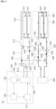
FIG. 1 is a view illustrating a hydrogen compression system according to an embodiment of the present disclosure. -
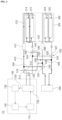
FIG. 2 is a view illustrating a process of heating a first compression part, and a process of cooling a second compression part of the hydrogen compression system according to an embodiment of the present disclosure. -
FIG. 3 is a view illustrating a process of cooling the first compression part, and a process of heating the second compression part of the hydrogen compression system according to an embodiment of the present disclosure. - The drawings described herein are for illustration purposes only and are not intended to limit the scope of the present disclosure in any way.
- Hereinafter, embodiments of the present disclosure are described in detail with reference to the accompanying drawings.
- However, the technical spirit of the present disclosure is not limited to some embodiments described herein but may be implemented in various different forms. One or more of the constituent elements in the embodiments may be selectively combined and substituted for use within the scope of the technical spirit of the present disclosure.
- In addition, unless otherwise specifically and explicitly defined and stated, the terms (including technical and scientific terms) used in the embodiments of the present disclosure may be construed as the meaning which may be commonly understood by the person with ordinary skill in the art to which the present disclosure pertains. The meanings of the commonly used terms such as the terms defined in dictionaries may be interpreted in consideration of the contextual meanings of the related technology.
- In addition, the terms used in the embodiments of the present disclosure are for explaining the embodiments, not for limiting the present disclosure.
- In the present specification, unless particularly stated otherwise, a singular form may also include a plural form. The expression "at least one (or one or more) of A, B, and C" may include one or more of all combinations that can be made by combining A, B, and C.
- In addition, the terms such as first, second, A, B, (a), and (b) may be used to describe constituent elements of the embodiments of the present disclosure.
- These terms are used only for the purpose of discriminating one constituent element from another constituent element, and the nature, the sequences, or the orders of the constituent elements are not limited by the terms.
- Further, when one constituent element is described as being 'connected', 'coupled', or 'attached' to another constituent element, one constituent element may be connected, coupled, or attached directly to another constituent element or connected, coupled, or attached to another constituent element through still another constituent element interposed therebetween. When a component, device, element, or the like of the present disclosure is described as having a purpose or performing an operation, function, or the like, the component, device, or element should be considered herein as being "configured to" meet that purpose or to perform that operation or function.
- In addition, the expression "one constituent element is provided or disposed above (on) or below (under) another constituent element" includes not only a case in which the two constituent elements are in direct contact with each other, but also a case in which one or more other constituent elements are provided or disposed between the two constituent elements. The expression "above (on) or below (under)" may mean a downward direction as well as an upward direction based on one constituent element.
- Referring to
FIGS. 1 to 3 , ahydrogen compression system 10 according to an embodiment of the present disclosure includes: aheat pump part 100 including aheat pump line 102 and configured to allow a refrigerant to circulate therethrough; ahydrogen compression part 300 configured to compress hydrogen by being repeatedly heated and cooled; afirst circulation line 410 connected to theheat pump line 102 while passing through thehydrogen compression part 300 and configured to allow the refrigerant introduced from theheat pump line 102 to circulate therethrough; asecond circulation line 420 configured to pass through thehydrogen compression part 300 and allow a cooling fluid to circulate therethrough; and a cooling unit provided in thesecond circulation line 420 and configured to cool the cooling fluid. Thehydrogen compression part 300 may be heated by the refrigerant or cooled by the cooling fluid. - For reference, the
hydrogen compression system 10 according to the present disclosure may be used to treat (compress) required hydrogen. The present disclosure is not restricted or limited by the characteristics and states of hydrogen treated by thehydrogen compression system 10. - According to the embodiment of the present disclosure, the
hydrogen compression system 10 may be used to compress hydrogen, produced by a steam reforming method (or water electrolysis), before the hydrogen is supplied to a supply destination (e.g., a high-pressure tank). According to another embodiment of the present disclosure, the hydrogen compression system may be used to compress again hydrogen that has been compressed once. - The
heat pump part 100 may include theheat pump line 102 through which the refrigerant circulates. The refrigerant circulating through theheat pump line 102 may be used as a heat medium for heating thehydrogen compression part 300. - The
heat pump part 100 may have various structures capable of converting thermal energy of a low-temperature object (e.g., the refrigerant) into high-temperature thermal energy by supplying mechanical energy from the outside. The present disclosure is not restricted or limited by the type and structure of theheat pump part 100. - According to the embodiment of the present disclosure, the
heat pump part 100 may include: acompressor 110 provided in theheat pump line 102 and configured to compress the refrigerant; acondenser 120 provided in theheat pump line 102 and configured to condense the refrigerant; anexpansion valve 130 provided in theheat pump line 102 and configured to decompress the refrigerant; and anevaporator 140 provided in theheat pump line 102 and configured to vaporize the refrigerant. - For example, the refrigerant may circulate through the
heat pump line 102 while sequentially passing through thecompressor 110, thecondenser 120, theexpansion valve 130, and theevaporator 140. According to another embodiment of the present disclosure, the refrigerant may circulate through the heat pump line while sequentially passing through the compressor, the evaporator, the expansion valve, and the condenser. - The
compressor 110 is configured to compress the low-pressure refrigerant into the high-pressure refrigerant. The present disclosure is not restricted or limited by the type and structure of thecompressor 110. - The
condenser 120 is a kind of heat exchanger configured to condense the high-temperature, high-pressure refrigerant by exchanging heat with air (or water). The present disclosure is not restricted or limited by the type and structure of thecondenser 120. - The
expansion valve 130 is a kind of decompression valve configured to reduce a pressure of the refrigerant having passed through thecondenser 120 and adjust a flow rate of the refrigerant. The present disclosure is not restricted or limited by the type and structure of theexpansion valve 130. - The
evaporator 140 is also a kind of heat exchanger configured to vaporize the refrigerant by exchanging heat with air (or water). The present disclosure is not restricted or limited by the type and structure of theevaporator 140. - The
hydrogen compression part 300 is configured to compress hydrogen by being repeatedly heated and cooled. - The
hydrogen compression part 300 may have various structures capable of compressing hydrogen by being repeatedly heated and cooled. The present disclosure is not restricted or limited by the structure of thehydrogen compression part 300. - For reference, in the embodiment of the present disclosure, the
hydrogen compression part 300 may be defined as thehydrogen compression part 300 that does not include a separate electric heat source (e.g., an electric heater) for heating metal hydride compressors. - According to an embodiment of the present disclosure, the
hydrogen compression part 300 may include afirst compression part 310 configured to compress hydrogen, and asecond compression part 320 configured to compress hydrogen independently of thefirst compression part 310. The first andsecond compression parts - According to another embodiment of the present disclosure, the hydrogen compression part may include three or more compression parts. Alternatively, the hydrogen compression part may include only one compression part.
- According to another embodiment of the present disclosure, the
first compression part 310 may include a first-firstmetal hydride compressor 312 configured to compress hydrogen, and a first-secondmetal hydride compressor 314 configured to compress hydrogen independently of the first-firstmetal hydride compressor 312. - In one form, the first-first
metal hydride compressor 312 and the first-secondmetal hydride compressor 314 may be connected in series. For example, the first-secondmetal hydride compressor 314 may be connected in series to a downstream side of the first-firstmetal hydride compressor 312. - According to another embodiment of the present disclosure, the first-first metal hydride compressor and the first-second metal hydride compressor may be connected in parallel.
- In addition, according to an embodiment of the present disclosure, the
second compression part 320 may include a second-firstmetal hydride compressor 322 configured to compress hydrogen, and a second-secondmetal hydride compressor 324 configured to compress hydrogen independently of the second-firstmetal hydride compressor 322. - In one form, the second-first
metal hydride compressor 322 and the second-secondmetal hydride compressor 324 may be connected in series. For example, the second-secondmetal hydride compressor 324 may be connected in series to a downstream side of the second-firstmetal hydride compressor 322. - According to another embodiment of the present disclosure, the second-first metal hydride compressor and the second-second metal hydride compressor may be connected in parallel.
- Each of the metal hydride compressors (the first-first
metal hydride compressor 312, the first-secondmetal hydride compressor 314, the second-firstmetal hydride compressor 322, and the second-second metal hydride compressor 324), which constitute thehydrogen compression part 300, is a metal hydride-based thermochemical compressor and may compress hydrogen by being repeatedly heated and cooled by using properties of a metal hydride material. - For example, the metal hydride compressors (the first-first
metal hydride compressor 312, the first-secondmetal hydride compressor 314, the second-firstmetal hydride compressor 322, and the second-second metal hydride compressor 324) of thehydrogen compression part 300 may have various structures and shapes each having a storage space therein. The present disclosure is not restricted or limited by the structure and shape of the metal hydride compressor. - The type of metal hydride material, which constitutes each of the metal hydride compressors (the first-first
metal hydride compressor 312, the first-secondmetal hydride compressor 314, the second-firstmetal hydride compressor 322, and the second-second metal hydride compressor 324) of thehydrogen compression part 300 may be variously changed in accordance with required conditions and design specifications. - For example, the metal hydride material may include at least one of an AB5-based alloy, an AB2-based alloy, or an AB-based alloy. For example, the metal hydride material may be an alloy containing LaNis, TiFe, TiMn2, and the like as main elements.
- For reference, the metal hydride material may be provided in the form of powder or pellets and accommodated in a container (not illustrated). The present disclosure is not restricted or limited by the accommodated state and shape of the metal hydride material. According to another embodiment of the present disclosure, the metal hydride material may be formed by compressing metal hydride powder or metal hydride pellets and have a bulk shape corresponding to the container.
- The
first circulation line 410 may be connected to theheat pump line 102 while passing through thehydrogen compression part 300. The refrigerant introduced from theheat pump line 102 may circulate through thefirst circulation line 410. - For example, the
first circulation line 410 may be connected to thecondenser 120 or theevaporator 140 through which the high-temperature refrigerant may flow. - In one embodiment, both ends (e.g., first and second ends) of the
first circulation line 410 are connected to thecondenser 120. With the above-mentioned structure, the high-temperature refrigerant discharged from thecompressor 110 may circulate through thefirst circulation line 410 via thecondenser 120 and then circulate through theheat pump line 102 via thecondenser 120. - For reference, in the embodiment of the present disclosure, the configuration in which the
first circulation line 410 passes through thehydrogen compression part 300 may mean that thefirst circulation line 410 is provided to exchange heat with (to heat) the metal hydride compressors (the first-firstmetal hydride compressor 312, the first-secondmetal hydride compressor 314, the second-firstmetal hydride compressor 322, and the second-second metal hydride compressor 324) that constitute thehydrogen compression part 300. - For example, the
first circulation line 410 may pass through interiors of the metal hydride compressors (the first-firstmetal hydride compressor 312, the first-secondmetal hydride compressor 314, the second-firstmetal hydride compressor 322, and the second-second metal hydride compressor 324) or surround the metal hydride compressors. - According to the embodiment of the present disclosure, the refrigerant supplied through the
first circulation line 410 may heat the metal hydride compressors (the first-firstmetal hydride compressor 312, the first-secondmetal hydride compressor 314, the second-firstmetal hydride compressor 322, and the second-second metal hydride compressor 324) through heat exchange by convection. - The refrigerant circulating through the
first circulation line 410 may be used as a heat medium for heating the metal hydride compressors (the first-firstmetal hydride compressor 312, the first-secondmetal hydride compressor 314, the second-firstmetal hydride compressor 322, and the second-second metal hydride compressor 324). - The
second circulation line 420 may pass through thehydrogen compression part 300, and the cooling fluid may circulate through thesecond circulation line 420. - The
second circulation line 420 may have various structures capable of passing through thehydrogen compression part 300. The present disclosure is not restricted or limited by the structure and shape of thesecond circulation line 420. - In the embodiment of the present disclosure, the configuration in which the
second circulation line 420 passes through thehydrogen compression part 300 may mean that thesecond circulation line 420 is provided to exchange heat with (to cool) the metal hydride compressors (the first-firstmetal hydride compressor 312, the first-secondmetal hydride compressor 314, the second-firstmetal hydride compressor 322, and the second-second metal hydride compressor 324) that constitute thehydrogen compression part 300. - For example, the
second circulation line 420 may pass through the interiors of the metal hydride compressors (the first-firstmetal hydride compressor 312, the first-secondmetal hydride compressor 314, the second-firstmetal hydride compressor 322, and the second-second metal hydride compressor 324) or surround the metal hydride compressors. - According to the embodiment of the present disclosure, the cooling fluid supplied through the
second circulation line 420 may cool the metal hydride compressors (the first-firstmetal hydride compressor 312, the first-secondmetal hydride compressor 314, the second-firstmetal hydride compressor 322, and the second-second metal hydride compressor 324) through heat exchange by convection. - The cooling fluid circulating through the
second circulation line 420 may be used to cool the metal hydride compressors (the first-firstmetal hydride compressor 312, the first-secondmetal hydride compressor 314, the second-firstmetal hydride compressor 322, and the second-second metal hydride compressor 324). - For reference, a typical liquid (e.g., coolant) or gas may be used as the cooling fluid. The present disclosure is not restricted or limited by the type and properties of the cooling fluid.
- The cooling unit is provided in the
second circulation line 420 and configured to cool the cooling fluid. - Various cooling means capable of cooling the cooling fluid may be used as the cooling unit. The present disclosure is not restricted or limited by the type and structure (method) of the cooling unit.
- For example, the cooling unit may be configured to cool the cooling fluid in a water-cooled manner (or air-cooled manner). According to another embodiment of the present disclosure, the cooling unit may be configured by using a Peltier element or other cooling means.
- As described above, according to the embodiment of the present disclosure, the first and
second compression parts - For example, the
second compression part 320 may be cooled while thefirst compression part 310 is heated (hydrogen is compressed). On the contrary, thefirst compression part 310 may be cooled while thesecond compression part 320 is heated (hydrogen is compressed). - As described above, the first and
second compression parts second compression parts - In one embodiment for alternately heating and cooling the first and
second compression parts hydrogen compression system 10 may include: afirst bypass line 430 having one end disposed at an upstream side of thefirst compression part 310 and connected to thefirst circulation line 410, and the other end disposed at an upstream side of thesecond compression part 320 and connected to thesecond circulation line 420; and asecond bypass line 440 having one end disposed at a downstream side of thesecond compression part 320 and connected to thesecond circulation line 420, and the other end disposed at a downstream side of thefirst compression part 310 and connected to thefirst circulation line 410. Thehydrogen compression system 10 may further include athird bypass line 450 having one end disposed at the upstream side of thesecond compression part 320 and connected to thesecond circulation line 420, and the other end disposed at the upstream side of thefirst compression part 310 and connected to thefirst circulation line 410; and afourth bypass line 460 having one end disposed at the downstream side of thefirst compression part 310 and connected to thefirst circulation line 410, and the other end disposed at the downstream side of thesecond compression part 320 and connected to thesecond circulation line 420. - The
first bypass line 430 is configured to supply the second circulation line 420 (the second compression part) with the refrigerant (the high-temperature refrigerant) that circulates through thefirst circulation line 410. - For example, one end of the
first bypass line 430 may be disposed at the upstream side of the first compression part 310 (e.g., between thecondenser 120 and an inlet end of the first compression part 310) and connected to thefirst circulation line 410. The other end of thefirst bypass line 430 may be disposed at the upstream side of the second compression part 320 (e.g., between the cooling unit and an inlet end of the second compression part 320) and connected to thesecond circulation line 420. - The
second bypass line 440 is configured to return the refrigerant having passed through thesecond compression part 320 to the first circulation line 410 (the heat pump line). - For example, one end of the
second bypass line 440 may be disposed at the downstream side of the second compression part 320 (e.g., between an outlet end of thesecond compression part 320 and the cooling unit) and connected to thesecond circulation line 420. The other end of thesecond bypass line 440 may be disposed at the downstream side of the first compression part 310 (e.g., between an outlet end of thefirst compression part 310 and the condenser 120) and connected to thefirst circulation line 410. - The
third bypass line 450 is configured to supply the first circulation line 410 (the first compression part) with the cooling fluid that circulates through thesecond circulation line 420. - For example, one end of the
third bypass line 450 may be disposed at the upstream side of the second compression part 320 (e.g., between the cooling unit and the inlet end of the second compression part 320) and connected to thesecond circulation line 420. The other end of thethird bypass line 450 may be disposed at the upstream side of the first compression part 310 (e.g., between thecondenser 120 and the inlet end of the first compression part 310) and connected to thefirst circulation line 410. - The
fourth bypass line 460 is configured to return the refrigerant having passed through thefirst compression part 310 to the second circulation line 420 (the cooling unit). - For example, one end of the
fourth bypass line 460 may be disposed at the downstream side of the first compression part 310 (e.g., between the outlet end of thefirst compression part 310 and the condenser 120) and connected to thefirst circulation line 410. The other end of thefourth bypass line 460 may be disposed at the downstream side of the second compression part 320 (e.g., between the outlet end of thesecond compression part 320 and the cooling unit) and connected to thesecond circulation line 420. - According to another embodiment of the present disclosure, the
hydrogen compression system 10 may include: afirst valve 510 provided in thefirst circulation line 410 and configured to selectively switch the flow path of the refrigerant introduced from theheat pump line 102 to thefirst bypass line 430; and asecond valve 520 provided in thesecond circulation line 420 and configured to selectively switch the flow path of the refrigerant having passed through thesecond compression part 320 to thesecond bypass line 440. Thehydrogen compression system 10 may further include: athird valve 530 provided in thesecond circulation line 420 and configured to selectively switch the flow path of the cooling fluid having passed through the cooling unit to thethird bypass line 450; and afourth valve 540 provided in thefirst circulation line 410 and configured to selectively switch the flow path of the cooling fluid having passed through thefirst compression part 310 to thefourth bypass line 460. - The
first valve 510 may be provided in thefirst circulation line 410 and positioned between thecondenser 120 and the inlet end of thefirst compression part 310. Thefirst bypass line 430 may be connected to thefirst valve 510. - Various valve means capable of selectively switching the flow path of the refrigerant introduced from the
heat pump line 102 to thefirst bypass line 430 may be used as thefirst valve 510. - For example, a typical three-way valve may be used as the
first valve 510. More specifically, thefirst valve 510 may include: a first-first port 512 connected to thefirst circulation line 410 so that the refrigerant introduced from theheat pump line 102 is introduced into thefirst valve 510; a first-second port 514 connected to thefirst circulation line 410 so that the refrigerant having passed through thefirst valve 510 is supplied to thefirst compression part 310; and a first-third port 516 connected to one end of thefirst bypass line 430. - It is possible to selectively switch the flow path of the refrigerant introduced from the
heat pump line 102 to thefirst bypass line 430 by selectively opening or closing the first-first port 512, the first-second port 514, and the first-third port 516 of thefirst valve 510. In other words, referring toFIG. 2 , at the time of heating the first compression part 310 (cooling the second compression part 320), when the first-first port 512 and the first-second port 514 are opened, and the first-third port 516 is closed, the refrigerant introduced from theheat pump line 102 may be supplied to thefirst compression part 310. In contrast, as illustrated inFIG. 3 , at the time of heating the second compression part 320 (cooling the first compression part 310), when the first-first port 512 and the first-third port 516 are opened, and the first-second port 514 is closed, the supply of the refrigerant to thefirst compression part 310 may be cut off, and the refrigerant introduced from theheat pump line 102 may be supplied to thesecond compression part 320 through thefirst bypass line 430. - The
second valve 520 may be provided in thesecond circulation line 420 and positioned between the outlet end of thesecond compression part 320 and the cooling unit. Thesecond bypass line 440 may be connected to thesecond valve 520. - Various valve means capable of selectively switching the flow path of the refrigerant having passed through the
second compression part 320 to thesecond bypass line 440 may be used as thesecond valve 520. - For example, a typical three-way valve may be used as the
second valve 520. More specifically, thesecond valve 520 may include: a second-first port 522 connected to thesecond circulation line 420 so that the refrigerant having passed through thesecond compression part 320 is introduced into thesecond valve 520; a second-second port 524 connected to thesecond circulation line 420 so that the cooling fluid having passed through thesecond valve 520 is supplied to the cooling unit (the refrigerant having passed through the second compression part is not supplied to the cooling unit); and a second-third port 526 connected to one end of thesecond bypass line 440. - It is possible to selectively switch the flow path of the refrigerant having passed through the
second compression part 320 to thesecond bypass line 440 by selectively opening or closing the second-first port 522, the second-second port 524, and the second-third port 526 of thesecond valve 520. In other words, referring toFIG. 2 , at the time of heating the first compression part 310 (cooling the second compression part 320), when the second-first port 522 and the second-second port 524 are opened, and the second-third port 526 is closed, the cooling fluid having passed through thesecond compression part 320 may be supplied to the cooling unit. In contrast, as illustrated inFIG. 3 , at the time of heating the second compression part 320 (cooling the first compression part 310), when the second-first port 522 and the second-third port 526 are opened, and the second-second port 524 is closed, the refrigerant having passed through thesecond compression part 320 may be supplied back to the first circulation line 410 (the heat pump line) through thesecond bypass line 440. - The
third valve 530 may be provided in thesecond circulation line 420 and positioned between the cooling unit and the inlet end of thesecond compression part 320. Thethird bypass line 450 may be connected to thethird valve 530. - Various valve means capable of selectively switching the flow path of the cooling fluid having passed through the cooling unit to the
third bypass line 450 may be used as thethird valve 530. - For example, a typical three-way valve may be used as the
third valve 530. More specifically, thethird valve 530 may include: a third-first port 532 connected to thesecond circulation line 420 so that the cooling fluid having passed through the cooling unit is introduced into thethird valve 530; a third-second port 534 connected to thesecond circulation line 420 so that the cooling fluid having passed through thethird valve 530 is supplied to thesecond compression part 320; and a third-third port 536 connected to one end of thesecond bypass line 440. - It is possible to selectively switch the flow path of the cooling fluid having passed through the cooling unit to the
third bypass line 450 by selectively opening or closing the third-first port 532, the third-second port 534, and the third-third port 536 of thethird valve 530. In other words, referring toFIG. 2 , at the time of heating the first compression part 310 (cooling the second compression part 320), when the third-first port 532 and the third-second port 534 are opened, and the third-third port 536 is closed, the cooling fluid having passed through the cooling unit may be supplied to thesecond compression part 320. In contrast, as illustrated inFIG. 3 , at the time of heating the second compression part 320 (cooling the first compression part 310), when the third-first port 532 and the third-third port 536 are opened, and the third-second port 534 is closed, the supply of the cooling fluid to thesecond compression part 320 may be cut off, and the cooling fluid having passed through the cooling unit may be supplied to thefirst compression part 310 through thethird bypass line 450. - The
fourth valve 540 may be provided in thefirst circulation line 410 and positioned between the outlet end of thefirst compression part 310 and thecondenser 120. Thefourth bypass line 460 may be connected to thefourth valve 540. - Various valve means capable of selectively switching the flow path of the cooling fluid having passed through the
first compression part 310 to thefourth bypass line 460 may be used as thefourth valve 540. - For example, a typical three-way valve may be used as the
fourth valve 540. More specifically, thefourth valve 540 may include: a fourth-first port 542 connected to thefirst circulation line 410 so that the cooling fluid having passed through thefirst compression part 310 is introduced into thefourth valve 540; a fourth-second port 544 connected to thefirst circulation line 410 so that the refrigerant having passed through thefourth valve 540 is supplied to the condenser 120 (the cooling fluid having passed through the first compression part is not supplied to the condenser); and a fourth-third port 546 connected to one end of thefourth bypass line 460. - It is possible to selectively switch the flow path of the cooling fluid having passed through the
first compression part 310 to thefourth bypass line 460 by selectively opening or closing the fourth-first port 542, the fourth-second port 544, and the fourth-third port 546 of thefourth valve 540. In other words, referring toFIG. 2 , at the time of heating the first compression part 310 (cooling the second compression part 320), when the fourth-first port 542 and the fourth-second port 544 are opened, and the fourth-third port 546 is closed, the refrigerant having passed through thefirst compression part 310 may be supplied to the cooling unit. In contrast, as illustrated inFIG. 3 , at the time of heating the second compression part 320 (cooling the first compression part 310), when the fourth-first port 542 and the fourth-third port 546 are opened, and the fourth-second port 544 is closed, the cooling fluid having passed through thefirst compression part 310 may be supplied back to the second circulation line 420 (the cooling unit) through thefourth bypass line 460. - With the above-mentioned structure, the first and
second compression parts - Referring to
FIG. 2 , at the time of heating thefirst compression part 310, the refrigerant circulating through thefirst circulation line 410 may heat the first-firstmetal hydride compressor 312 and the first-secondmetal hydride compressor 314 by sequentially passing through the first-firstmetal hydride compressor 312 and the first-secondmetal hydride compressor 314. - In addition, as illustrated in
FIG. 2 , thesecond compression part 320 may be cooled while thefirst compression part 310 is heated. At the time of cooling thesecond compression part 320, the cooling fluid circulating through thesecond circulation line 420 may cool the second-firstmetal hydride compressor 322 and the second-secondmetal hydride compressor 324 by sequentially passing through the second-firstmetal hydride compressor 322 and the second-secondmetal hydride compressor 324. - In contrast, referring to
FIG. 3 , at the time of heating thesecond compression part 320, the refrigerant circulating through thefirst circulation line 410 may heat the second-firstmetal hydride compressor 322 and the second-secondmetal hydride compressor 324 by sequentially passing through the second-firstmetal hydride compressor 322 and the second-secondmetal hydride compressor 324 via thefirst bypass line 430. Thereafter, the refrigerant having passed through the second compression part 320 (the second-firstmetal hydride compressor 322 and the second-second metal hydride compressor 324) may be supplied back to thefirst circulation line 410 through thesecond bypass line 440. - In addition, as illustrated in
FIG. 3 , thefirst compression part 310 may be cooled while thesecond compression part 320 is heated. At the time of cooling thefirst compression part 310, the cooling fluid circulating through thesecond circulation line 420 may cool the first-firstmetal hydride compressor 312 and the first-secondmetal hydride compressor 314 by sequentially passing through the first-firstmetal hydride compressor 312 and the first-secondmetal hydride compressor 314 via thethird bypass line 450. Thereafter, the cooling fluid having passed through the first compression part 310 (the first-firstmetal hydride compressor 312 and the first-second metal hydride compressor 314) may be supplied back to thesecond circulation line 420 through thefourth bypass line 460. - The embodiments of the present disclosure are illustrated and described above as the first and
second compression parts - According to the embodiment of the present disclosure, the
hydrogen compression system 10 may include: afirst heater 412 provided in thefirst circulation line 410, positioned between thefirst valve 510 and thefirst compression part 310, and configured to heat the refrigerant; and asecond heater 422 provided in thesecond circulation line 420, positioned between thethird valve 530 and thesecond compression part 320, and configured to heat the refrigerant. - The
first heater 412 is configured to heat the refrigerant to be supplied to thefirst compression part 310 through thefirst circulation line 410. - Various heating means capable of heating the refrigerant to be supplied to the
first compression part 310 through thefirst circulation line 410 may be used as thefirst heater 412. The present disclosure is not restricted or limited by the type and structure of thefirst heater 412. For example, a typical electric heater may be used as thefirst heater 412. - As described above, in the embodiment of the present disclosure, the
first heater 412 may be provided in thefirst circulation line 410, and thefirst heater 412 may additionally heat the refrigerant to be supplied to thefirst compression part 310 at the time of heating thefirst compression part 310. Therefore, it is possible to obtain an advantageous effect of increasing the heating capacity and heating speed of thefirst compression part 310. - The
second heater 422 is configured to heat the refrigerant to be supplied tosecond compression part 320 through thesecond circulation line 420 via thefirst bypass line 430. - Various heating means capable of heating the refrigerant to be supplied to the
second compression part 320 through thesecond circulation line 420 may be used as thesecond heater 422. The present disclosure is not restricted or limited by the type and structure of thesecond heater 422. For example, a typical electric heater may be used as thesecond heater 422. - As described above, in the embodiment of the present disclosure, the
second heater 422 may be provided in thesecond circulation line 420, and thesecond heater 422 may additionally heat the refrigerant to be supplied to thesecond compression part 320 at the time of heating thesecond compression part 320. Therefore, it is possible to obtain an advantageous effect of increasing the heating capacity and heating speed of thesecond compression part 320. - As described above, according to the embodiment of the present disclosure, it is possible to obtain an advantageous effect of minimizing electric power consumption and improving energy efficiency when compressing hydrogen by using the thermochemical method.
- In particular, according to the embodiments of the present disclosure, it is possible to operate the metal hydride compressor by using the refrigerant of the heat pump part as a heat source. Therefore, it is possible to obtain an advantageous effect of minimizing electric power consumption required for the process of compressing hydrogen and an advantageous effect of improving energy efficiency.
- In addition, according to the embodiments of the present disclosure, it is possible to obtain an advantageous effect of continuously extracting high-pressure hydrogen and reducing the time required for the process of compressing hydrogen.
- While the embodiments have been described above, the embodiments are just illustrative and not intended to limit the present disclosure. It can be appreciated by those having ordinary skill in the art that various modifications and applications, which are not described above, may be made to the present embodiment without departing from the intrinsic features of the present embodiment. For example, the respective constituent elements specifically described in the embodiments may be modified and then carried out. Further, it should be interpreted that the differences related to the modifications and applications are included in the scope of the present disclosure.
Claims (10)
- A hydrogen compression system comprising:a heat pump part comprising a heat pump line configured to allow a refrigerant to circulate therethrough;a hydrogen compression part configured to compress hydrogen by being repeatedly heated and cooled;a first circulation line connected to the heat pump line while passing through the hydrogen compression part and configured to allow the refrigerant introduced from the heat pump line to circulate therethrough;a second circulation line provided to pass through the hydrogen compression part and configured to allow a cooling fluid to circulate therethrough; anda cooling unit provided in the second circulation line and configured to cool the cooling fluid,wherein the hydrogen compression part is heated by the refrigerant or cooled by the cooling fluid.
- The hydrogen compression system of claim 1, wherein the hydrogen compression part comprises:a first compression part configured to compress the hydrogen; anda second compression part configured to compress hydrogen independently of the first compression part, andwherein the first and second compression parts are alternately heated or cooled.
- The hydrogen compression system of claim 2, wherein the first compression part comprises:a first-first metal hydride compressor configured to compress hydrogen; anda first-second metal hydride compressor configured to compress hydrogen independently of the first-first metal hydride compressor.
- The hydrogen compression system of claim 3, wherein the first-first metal hydride compressor and the first-second metal hydride compressor are connected in series.
- The hydrogen compression system of one of claims 2-4, wherein the second compression part comprises:a second-first metal hydride compressor configured to compress hydrogen; anda second-second metal hydride compressor configured to compress hydrogen independently of the second-first metal hydride compressor.
- The hydrogen compression system of claim 5, wherein the second-first metal hydride compressor and the second-second metal hydride compressor are connected in series.
- The hydrogen compression system of one of claims 2-6, comprising:a first bypass line having a first end disposed at an upstream side of the first compression part and connected to the first circulation line, and a second end disposed at an upstream side of the second compression part and connected to the second circulation line;a second bypass line having a first end disposed at a downstream side of the second compression part and connected to the second circulation line, and a second end disposed at a downstream side of the first compression part and connected to the first circulation line;a third bypass line having a first end disposed at the upstream side of the second compression part and connected to the second circulation line, and a second end disposed at the upstream side of the first compression part and connected to the first circulation line; anda fourth bypass line having a first end disposed at the downstream side of the first compression part and connected to the first circulation line, and a second end disposed at the downstream side of the second compression part and connected to the second circulation line.
- The hydrogen compression system of claim 7, comprising:a first valve provided in the first circulation line and configured to selectively switch a flow path of the refrigerant introduced from the heat pump line to the first bypass line;a second valve provided in the second circulation line and configured to selectively switch a flow path of the refrigerant having passed through the second compression part to the second bypass line;a third valve provided in the second circulation line and configured selectively switch a flow path of the cooling fluid having passed through the cooling unit to the third bypass line; anda fourth valve provided in the first circulation line and configured to selectively switch a flow path of the cooling fluid having passed through the first compression part to the fourth bypass line.
- The hydrogen compression system of claim 8, comprising:a first heater provided in the first circulation line, positioned between the first valve and the first compression part, and configured to heat the refrigerant; anda second heater provided in the second circulation line, positioned between the third valve and the second compression part, and configured to heat the refrigerant.
- The hydrogen compression system of one of claims 1-9, wherein the heat pump part comprises:a compressor provided in the heat pump line and configured to compress the refrigerant;a condenser provided in the heat pump line and configured to condense the refrigerant;an expansion valve provided in the heat pump line and configured to decompress the refrigerant; andan evaporator provided in the heat pump line and configured to vaporize the refrigerant, andwherein the first circulation line is connected to the condenser or the evaporator.
Applications Claiming Priority (1)
| Application Number | Priority Date | Filing Date | Title |
|---|---|---|---|
| KR1020220148796A KR20240067595A (en) | 2022-11-09 | 2022-11-09 | Hydrogen compression system |
Publications (1)
| Publication Number | Publication Date |
|---|---|
| EP4368566A1 true EP4368566A1 (en) | 2024-05-15 |
Family
ID=86776503
Family Applications (1)
| Application Number | Title | Priority Date | Filing Date |
|---|---|---|---|
| EP23179161.7A Pending EP4368566A1 (en) | 2022-11-09 | 2023-06-14 | Hydrogen compression system |
Country Status (4)
| Country | Link |
|---|---|
| US (1) | US12385674B2 (en) |
| EP (1) | EP4368566A1 (en) |
| KR (1) | KR20240067595A (en) |
| CN (1) | CN118004964A (en) |
Citations (4)
| Publication number | Priority date | Publication date | Assignee | Title |
|---|---|---|---|---|
| JPH01305273A (en) * | 1988-06-03 | 1989-12-08 | Seijiro Suda | Metal hydride heat pump |
| US4995235A (en) * | 1988-03-17 | 1991-02-26 | Huit Gesellschaft Fur-Hydrid-Und Wasserstofftechnik M.B.H. | Method and apparatus for compressing hydrogen gas |
| US20120198884A1 (en) * | 2005-08-22 | 2012-08-09 | Golben P Mark | Method for Production of Carbon Dioxide and Apparatus Therefor |
| US20210396429A1 (en) * | 2018-02-09 | 2021-12-23 | Xergy Inc | High pressure hydrogen electrical power generator |
Family Cites Families (3)
| Publication number | Priority date | Publication date | Assignee | Title |
|---|---|---|---|---|
| US4108605A (en) * | 1976-05-04 | 1978-08-22 | Billings Energy Corporation | Hydrogen purification and storage system |
| CN100448083C (en) * | 2004-05-19 | 2008-12-31 | 松下电器产业株式会社 | fuel cell system |
| US12487023B2 (en) * | 2023-07-25 | 2025-12-02 | Heatcraft Refrigeration Products Llc | Refrigeration system and method of defrosting the same |
-
2022
- 2022-11-09 KR KR1020220148796A patent/KR20240067595A/en active Pending
-
2023
- 2023-06-14 EP EP23179161.7A patent/EP4368566A1/en active Pending
- 2023-06-23 US US18/213,318 patent/US12385674B2/en active Active
- 2023-07-05 CN CN202310815080.5A patent/CN118004964A/en active Pending
Patent Citations (4)
| Publication number | Priority date | Publication date | Assignee | Title |
|---|---|---|---|---|
| US4995235A (en) * | 1988-03-17 | 1991-02-26 | Huit Gesellschaft Fur-Hydrid-Und Wasserstofftechnik M.B.H. | Method and apparatus for compressing hydrogen gas |
| JPH01305273A (en) * | 1988-06-03 | 1989-12-08 | Seijiro Suda | Metal hydride heat pump |
| US20120198884A1 (en) * | 2005-08-22 | 2012-08-09 | Golben P Mark | Method for Production of Carbon Dioxide and Apparatus Therefor |
| US20210396429A1 (en) * | 2018-02-09 | 2021-12-23 | Xergy Inc | High pressure hydrogen electrical power generator |
Also Published As
| Publication number | Publication date |
|---|---|
| US12385674B2 (en) | 2025-08-12 |
| CN118004964A (en) | 2024-05-10 |
| KR20240067595A (en) | 2024-05-17 |
| US20240151436A1 (en) | 2024-05-09 |
Similar Documents
| Publication | Publication Date | Title |
|---|---|---|
| Tarasov et al. | Metal hydride hydrogen compressors for energy storage systems: layout features and results of long-term tests | |
| CN115333248B (en) | Liquid carbon dioxide energy storage system and microgrid system for islands and reefs | |
| US20220205592A1 (en) | Combined hydrogen storage - compression system for the filling of high pressure hydrogen tanks | |
| NO330286B1 (en) | Continuously operated hydrogen compressor and method of operation thereof | |
| CN118327714A (en) | Compressed air energy storage system | |
| CN110566294A (en) | power generation and energy storage method and system | |
| Ozsaban et al. | A parametric study on exergetic sustainability aspects of high-pressure hydrogen gas compression | |
| US20240151360A1 (en) | Hydrogen supply module and hydrogen supply method | |
| CN118327732A (en) | Compressed air energy storage system capable of utilizing waste heat | |
| US12385674B2 (en) | Hydrogen compression system | |
| CN101298949A (en) | Heat pump | |
| CN115031567B (en) | A heat recovery system, a compression energy storage system and a heat recovery method | |
| CN116659160A (en) | Combined heating and cooling compressed air energy storage system | |
| CN119268173B (en) | A solid-state hydrogen storage thermal management system and method combining heat pump and cold and heat storage | |
| US20240151361A1 (en) | Hydrogen supply module and hydrogen supply method | |
| CN220187509U (en) | Time-staggered shared heat exchanger system and compressed air energy storage power station | |
| CN111305922B (en) | Liquid air energy storage system | |
| EP4582732A1 (en) | Method for removing boil off gas when storing cryogenic fluid and corresponding system | |
| US20240151366A1 (en) | Hydrogen supply module and hydrogen supply method | |
| US20240151364A1 (en) | Hydrogen supply module and hydrogen supply method | |
| US20250305493A1 (en) | Gas compression system and method for recovering hydrogen | |
| CN117627744B (en) | Supercritical carbon dioxide energy storage power generation system and method coupled with solid thermal storage | |
| Brestovič et al. | Heat Pump Application at Hydrogen Compression While using Metal Hydride Materials | |
| JPH07243717A (en) | Hydrogen absorbing alloy heat pump | |
| JP2019019884A (en) | Hydrogen booster system |
Legal Events
| Date | Code | Title | Description |
|---|---|---|---|
| PUAI | Public reference made under article 153(3) epc to a published international application that has entered the european phase |
Free format text: ORIGINAL CODE: 0009012 |
|
| STAA | Information on the status of an ep patent application or granted ep patent |
Free format text: STATUS: THE APPLICATION HAS BEEN PUBLISHED |
|
| AK | Designated contracting states |
Kind code of ref document: A1 Designated state(s): AL AT BE BG CH CY CZ DE DK EE ES FI FR GB GR HR HU IE IS IT LI LT LU LV MC ME MK MT NL NO PL PT RO RS SE SI SK SM TR |
|
| STAA | Information on the status of an ep patent application or granted ep patent |
Free format text: STATUS: REQUEST FOR EXAMINATION WAS MADE |
|
| 17P | Request for examination filed |
Effective date: 20241115 |
|
| RBV | Designated contracting states (corrected) |
Designated state(s): AL AT BE BG CH CY CZ DE DK EE ES FI FR GB GR HR HU IE IS IT LI LT LU LV MC ME MK MT NL NO PL PT RO RS SE SI SK SM TR |
|
| P01 | Opt-out of the competence of the unified patent court (upc) registered |
Free format text: CASE NUMBER: APP_3855/2025 Effective date: 20250123 |