EP4368564A1 - Extraktionseinheit zum extrahieren eines roboters - Google Patents
Extraktionseinheit zum extrahieren eines roboters Download PDFInfo
- Publication number
- EP4368564A1 EP4368564A1 EP23173777.6A EP23173777A EP4368564A1 EP 4368564 A1 EP4368564 A1 EP 4368564A1 EP 23173777 A EP23173777 A EP 23173777A EP 4368564 A1 EP4368564 A1 EP 4368564A1
- Authority
- EP
- European Patent Office
- Prior art keywords
- extraction unit
- robot
- control points
- spline
- radiuses
- Prior art date
- Legal status (The legal status is an assumption and is not a legal conclusion. Google has not performed a legal analysis and makes no representation as to the accuracy of the status listed.)
- Withdrawn
Links
Images






Classifications
-
- B—PERFORMING OPERATIONS; TRANSPORTING
- B66—HOISTING; LIFTING; HAULING
- B66F—HOISTING, LIFTING, HAULING OR PUSHING, NOT OTHERWISE PROVIDED FOR, e.g. DEVICES WHICH APPLY A LIFTING OR PUSHING FORCE DIRECTLY TO THE SURFACE OF A LOAD
- B66F19/00—Hoisting, lifting, hauling or pushing, not otherwise provided for
-
- B—PERFORMING OPERATIONS; TRANSPORTING
- B66—HOISTING; LIFTING; HAULING
- B66F—HOISTING, LIFTING, HAULING OR PUSHING, NOT OTHERWISE PROVIDED FOR, e.g. DEVICES WHICH APPLY A LIFTING OR PUSHING FORCE DIRECTLY TO THE SURFACE OF A LOAD
- B66F15/00—Crowbars or levers
-
- E—FIXED CONSTRUCTIONS
- E04—BUILDING
- E04H—BUILDINGS OR LIKE STRUCTURES FOR PARTICULAR PURPOSES; SWIMMING OR SPLASH BATHS OR POOLS; MASTS; FENCING; TENTS OR CANOPIES, IN GENERAL
- E04H4/00—Swimming or splash baths or pools
- E04H4/14—Parts, details or accessories not otherwise provided for
-
- E—FIXED CONSTRUCTIONS
- E04—BUILDING
- E04H—BUILDINGS OR LIKE STRUCTURES FOR PARTICULAR PURPOSES; SWIMMING OR SPLASH BATHS OR POOLS; MASTS; FENCING; TENTS OR CANOPIES, IN GENERAL
- E04H4/00—Swimming or splash baths or pools
- E04H4/14—Parts, details or accessories not otherwise provided for
- E04H4/16—Parts, details or accessories not otherwise provided for specially adapted for cleaning
- E04H4/1654—Self-propelled cleaners
-
- B—PERFORMING OPERATIONS; TRANSPORTING
- B66—HOISTING; LIFTING; HAULING
- B66F—HOISTING, LIFTING, HAULING OR PUSHING, NOT OTHERWISE PROVIDED FOR, e.g. DEVICES WHICH APPLY A LIFTING OR PUSHING FORCE DIRECTLY TO THE SURFACE OF A LOAD
- B66F2700/00—Lifting apparatus
- B66F2700/09—Other lifting devices
Definitions
- Robots that are cordless may perform various operations within a pool and from time to time should be extracted from the pool.
- a robot that is cordless may be battery powered.
- the robot When the battery is empty the robot should be extracted from the pool (even from the bottom of the pool) - without the assistance of a cable that is connected to the robot.
- Manual extraction of a robot may require a human to guide an end of the extraction unit through a path till reaching a robot interface that is formed in an exterior of the robot, while the robot interface is still submerged - and while the image of the path itself is distorted due to the refraction of light rays as they travel from the fluid of the pool into the air.
- the problem is even more acute when the robot interface is at least partially hidden from the human.
- an extraction unit may include a handle, a bendable intermediate element, and an extraction unit interfacing element that is configured to interface with the robot.
- the bendable intermediate element is connected between the handle and the extraction unit interfacing element.
- the method may include extracting the robot by an extraction unit.
- the extraction unit may include a handle, a bendable intermediate element, and an extraction unit interfacing element that is configured to interface with the robot.
- the bendable intermediate element is connected between the handle and the extraction unit interfacing element.
- pool means any vessel that is capable of containing fluid.
- an extraction unit may include a handle, a bendable intermediate element and extraction unit interfacing element.
- the bendable intermediate element is connected between the handle and the extraction unit interfacing element.
- the extraction unit interfacing element is configured to interface with a robot.
- the bendable intermediate element may be flexible or may not be flexible.
- the bendable intermediate element may include multiple elements that are movably coupled to each other - they can move in relation to each other.
- the bendable intermediate element may be configured to change, under compression, a distance between the handle and the extraction unit interfacing element.
- the bendable intermediate may be compresses along a compression axis (denoted 72 in figure 1 ) that is parallel to a longitudinal axis (denoted 71 in figure 1 ) of the handle.
- Figure 1 illustrates an example of extraction unit 10.
- Extraction unit 10 includes handle 40 (having longitudinal axis 71), a bendable intermediate element 50 (having compression axis 72), and an extraction unit interfacing element 60.
- the bendable intermediate element 50 is connected between the handle 40 and the extraction unit interfacing element 60.
- the bendable intermediate element of figure 1 is flexible - although the bendable intermediate element may not be flexible - and may, for example, include multiple elements that are movably coupled to each other - they can move in relation to each other.
- the bendable intermediate element 50 forms a S-shaped spring.
- the bendable intermediate element may include linear segments and/or non-linear segments - for example may include alternating linear and non-linear segments.
- the bendable intermediate element is illustrated as including top segment 51 that is curved, a first intermediate segment 52 that is linear, a second intermediate segment 53 that has a curved section, a third intermediate segment 54 that is linear, a fourth intermediate segment 55 that has a curved section, a fifth intermediate segment 56 that is linear, and a bottom segment 57 that is curved.
- Each curved section may have two legs and an angle between the legs may be of any value - for example - may range between 30 degrees to 170 degrees, may range between 80 degrees and 120 degrees, and the like.
- the extraction unit interfacing element may include a hook, may include one or more arched sections, one or more linear section or a combination thereof.
- the extraction unit interfacing element is illustrated as including a hook that is formed from a linear top interfacing element segment 61, a curved interfacing element segment 62, and a linear end segment 63 that contacts rod 69.
- the rod may be connected to another section of the extraction unit interfacing element (for example to an arched section).
- the rod may have a longitudinal axis that is oriented to a longitudinal axis of the arched section.
- the orientation may be a normal orientation of a non-normal orientation.
- the linear end segment 63 has a longitudinal axis 74 that is oriented to a longitudinal axis 75 of rod 69 and is oriented to the longitudinal axis 73 of the linear top interfacing element segment 61.
- the extraction unit interfacing element may include any combination of segments having any shape and having any spatial relationships between them.
- the longitudinal axis 73 of the linear top interfacing element segment 61 is illustrated as being parallel to the compression axis 72 and the longitudinal axis 71 of the handle. There may be any spatial relationships between the different axes.
- the rod is shaped and sized to interface with a robot interface. Especially, the rod may maintain its contact with the robot interface during the extraction of the pool.
- the robot interface may be a female connector while the extraction unit interfacing element may be a male connector.
- the robot interface may be a male connector while the extraction unit interfacing element may be a female connector.
- the robot interface may include a recess while the extraction unit interfacing element may include a protuberance.
- the robot interface may include a protuberance while the extraction unit interfacing element may include a recess.
- the extraction unit is elevated during the extraction process and the robot includes one or more elements (for example countering element 110 of figure 4 ) that counters the upward motion - in the sense that the robot may include the robot interface and maybe also one or more additional elements that are located above a segment of the extraction unit interfacing element.
- elements for example countering element 110 of figure 4
- the robot may include the robot interface and maybe also one or more additional elements that are located above a segment of the extraction unit interfacing element.
- the bendable intermediate element is configured to convert a compression along a compression axis to an angular movement of the extraction unit interfacing element - especially when the extraction unit interfacing element is pressed against or contacts a pool cleaning robot.
- the angular movement may cause the extraction unit interfacing element to rotate about a rotation axis.
- the rotation axis may formed at a contact point between the extraction unit interfacing element and the bendable intermediate element, near the contact point (for example up to 1-5 centimeters from the contact point), and the like.
- the rotation may cause the rod (or other equivalent element of the extraction unit interfacing element) to fit himself to the robot interface - when the robot interface is reached by performing a rotational movement. For example - when the robot interface is oriented to a top of an inner space through which the extraction unit interfacing element is inserted.
- Figure 2 illustrates two examples of extraction units 10' and 10" that differ from extraction unit 10 of figure 1 by their bendable intermediate elements.
- Extraction unit 10" includes a bendable intermediate element 50' that is a spring that includes a spiral wire.
- the spiral wire has a symmetry axis that may be parallel to the longitudinal axis of the handle.
- Extraction unit 10' includes a bendable intermediate element 50" that includes a bulk that has a top bulk part 51", a middle bulk part 52" and a bottom bulk part 53" that are made of an elastic material such as an elastomer.
- An elastomer is a polymer with viscoelasticity (i.e., both viscosity and elasticity) and with weak intermolecular forces.
- the elastomer may be a natural rubber, a styrene-butadiene block copolymer, a polyisoprene, a polybutadiene, an ethylene propylene rubber, ethylene propylene diene rubber, silicone elastomers, a fluoroelastomer, a polyurethane elastomer, a nitrile rubber, and the like.
- FIG. 3 illustrates an example of an extraction unit 10 that contacts a robot 100 - a part of the extraction unit interfacing element is now shown because it is positioned within an inner space 102 formed by the housing 101 of the robot.
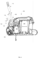
- Figure 4 illustrates a cross sectional view of a robot 100 and of the extraction unit 10 that contacts a robot interface 115. It should be noted that while figure 4 illustrates robot interface 115 that may be dedicated for interfacing with the extraction unit - one or more other parts of the robot (even parts that have other roles) may be used as an interface of the robot - for example a handle, a recess, and the like.
- the robot 100 of figure 4 is a pool cleaning robot - although the extraction unit may be used to extract robots other than pool cleaning robots.
- the robot 100 is illustrated as including filtering unit 121, impeller 123, pump motor 122, front brush wheel 124, housing 101, robot interface 115 and various portions of the robot that are proximate to the robot interface 115.
- the inner space 102 has a curved cross section - it has a top part that is located to the right (closer to the rear part of the robot) of the robot interface 115, and has a lower part is closer to the front wall 111 of the housing 101.
- the robot 100 includes a countering element 110 that includes the robot interface 115 a base segment 114, a rear segment 113, a top segment 112 and a front segment 111.
- the robot interface is positioned at meeting point between the base segment 114 and a front segment 116 of the inner space 102.
- the extraction unit interfacing element In order to contact the robot interface - the extraction unit interfacing element has to enter the inner space and the perform a clockwise rotation.
- the clockwise rotation is result of compressing the bendable intermediate element.
- the method may include extracting the robot by an extraction unit.
- the extraction unit may include a handle, a bendable intermediate element, and an extraction unit interfacing element that is configured to interface with the robot.
- the bendable intermediate element is connected between the handle and the extraction unit interfacing element.
- the method may include compressing the bendable intermediate element.
- the method may include extracting the robot by any of the extraction units illustrated in the application.
- the method may be executed by human or by a mechanical elements or mechanical device such as a robot that contacts the extraction unit.
- an extraction unit may include a handle; and an extraction unit interfacing element that is configured to interface with a robot.
- the extraction unit exterior forms an internal spline and an external spline that differ from each other, wherein the internal spline and the external spline define an asymmetrical hook.
- the internal spline may be defined by five to eight control points that are associated with different radiuses.
- the external spline may be defined by five to eight control points that are associated with different radiuses.
- Each one of the internal spline and the external spline may be defined by a same number of control points.
- the internal spline and the external spline may be defined by different numbers of control points.
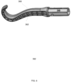
- Figures 5-6 illustrates an example of an extraction unit 300 that includes a handle 340 and an extraction unit interfacing element 360.
- the extraction unit interfacing element 360 may include ribs 362 that define inner spaces and such a construction may be applied in at least a part of the extraction unit interfacing element 60 of extraction unit 10.
- the extraction unit interfacing element 360 may be made of a bendable material.
- FIGS 7-9 illustrate extractions of robots (which may be a pool cleaning robot) that has a body and a countering element 410 such as a handle - that may be located above inner space 401 in which the edge of the extraction unit 300 is inserted.
- robots which may be a pool cleaning robot
- a countering element 410 such as a handle - that may be located above inner space 401 in which the edge of the extraction unit 300 is inserted.
- the extraction unit 300 is configured to support angles of approach that may range between 20-50 degrees or between 40°-70 °. When lifting the robot, the angle may be shifted to 25°-30 ° - and the extraction unit will not allow the robot to disengage and fall.
- the extraction unit may be tailored to a single model of robot - or may be adapted to extract multiple robots.
- An extraction unit may be designed while taking into account the extraction of different pool cleaning robots from different pools and having different distances between the user and the robot, the relationship between the shape of the extraction unit and the size and the shape of the pool cleaning robot, the center of gravity of the pool cleaning robot and the match / interface between the extraction unit and the robot, the location from which the robot is extracted from the pool, the shape of the countering element and/or a pace surrounding the countering element, the part of the extraction unit that is contacted by the user, optimal and/or sub-optical contact points with the hand of the user, shapes and sizes of recesses and/or inner spaces formed by the robot.
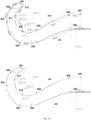
- FIGS 10-11 illustrates an example of an extraction unit.
- An exterior of a cross section of the extraction unit interfacing element comprises an interior spline 540 and exterior spline 530.
- the interior spline may be defined control points 507, 508, 509, 510, 511 and 512 - each is associated with a radius of a minimal circle that defines the curvature of the interior spline at the control point (in figure 10 the radiuses of control points 507, 508, 509, 510, 511 are 84.7 mm,, 90mm, 89.4 mm, 60.4 mm and 40.8 mm, respectively).
- control points 511 and 512 can be connected to each other in any manner - by a spline portion, by hale a circle, and the like.
- control points 507 and 508 is 20 mm
- the distance between control points 508 and 509 is 75mm
- the distance between control points 509 and 510 is 25mm
- the distance between control points 510 and 511 is 31 mm
- the distance between control points 511 and 512 is 20mm.
- the exterior spline may be defined control points 506, 505, 504, 503, 503 and 501 - each is associated with a radius of a minimal circle that defines the curvature of the interior spline at the control point (in figure 10 the radiuses of control points 506, 505, 504, 503, 502 and 501 are 58.5 mm, 60.4 mm, 20.2 mm, 40.8 mm 4.6 mm, and 9.4 mm respectively).
- control points 506 and 505 The distance between control points 506 and 505 is 97 mm, the distance between control points 505 and 504 is 28mm, the distance between control points 504 and 503 is 35mm, the distance between control points 503 and 502 is 23 mm, and the distance between control points 502 and 511 is 20mm.
- the other extraction unit may slightly differ from the other extraction unit of figure 5 .
- “Slightly differs” may be also referred to as “about” and may include a deviation of up to 5%, 10%, 15%, 20$, 25%, 30% of one or more distance between adjacent control points and/or of one or more radius of minimal circle.
- “Slightly differs” may be also referred to as “about” and may include a deviation of up to 1, 2, 3, 4, 5, 6, 7, 8, mm of one or more radius of minimal circle.
- “Slightly differs” may be also referred to as “about” and may include a deviation of up to 1, 2, 3, 4, 5, 6, 7, 8, 9, 10, 11, 12, 13, 14, 15, 20 mm of one or more distances between adjacent control points.
- Slightly differs may be also referred to as “about” and may include a deviation of up to 5%, 10%, 15%, 20%, 25%, 30/5 of a ratio between radiuses of minimal circuits of one or more pairs of control points.
- any arrangement of components to achieve the same functionality is effectively “associated” such that the desired functionality is achieved.
- any two components herein combined to achieve a particular functionality may be seen as “associated with” each other such that the desired functionality is achieved, irrespective of architectures or intermedial components.
- any two components so associated can also be viewed as being “operably connected,” or “operably coupled,” to each other to achieve the desired functionality.
- condition X may be fulfilled.
- This phrase also suggests that condition X may not be fulfilled.
- any reference to a robot as including a certain component should also cover the scenario in which the robot does not include the certain component.
- any reference to a method as including a certain step should also cover the scenario in which the method does not include the certain component.
- any reference to a robot that is configured to perform a certain operation should also cover the scenario in which the robot is not configured to perform the certain operation.
- any arrangement of components to achieve the same functionality is effectively “associated” such that the desired functionality is achieved.
- any two components herein combined to achieve a particular functionality can be seen as “associated with” each other such that the desired functionality is achieved, irrespective of architectures or intermedial components.
- any two components so associated can also be viewed as being “operably connected,” or “operably coupled,” to each other to achieve the desired functionality.
- any reference signs placed between parentheses shall not be construed as limiting the claim.
- the word 'comprising' does not exclude the presence of other elements or steps then those listed in a claim.
- the terms "a” or “an,” as used herein, are defined as one as or more than one.
- the use of introductory phrases such as “at least one " and “one or more " in the claims should not be construed to imply that the introduction of another claim element by the indefinite articles "a “ or “an” limits any particular claim containing such introduced claim element to inventions containing only one such element, even when the same claim includes the introductory phrases “one or more " or “at least one " and indefinite articles such as "a " or “an.
Landscapes
- Engineering & Computer Science (AREA)
- Structural Engineering (AREA)
- Architecture (AREA)
- Life Sciences & Earth Sciences (AREA)
- Geology (AREA)
- Mechanical Engineering (AREA)
- Civil Engineering (AREA)
- Manipulator (AREA)
Applications Claiming Priority (2)
| Application Number | Priority Date | Filing Date | Title |
|---|---|---|---|
| IL291426A IL291426B2 (en) | 2022-03-16 | 2022-03-16 | Dispensing unit for dispensing a robot |
| US202263383696P | 2022-11-14 | 2022-11-14 |
Publications (1)
| Publication Number | Publication Date |
|---|---|
| EP4368564A1 true EP4368564A1 (de) | 2024-05-15 |
Family
ID=86387060
Family Applications (1)
| Application Number | Title | Priority Date | Filing Date |
|---|---|---|---|
| EP23173777.6A Withdrawn EP4368564A1 (de) | 2022-03-16 | 2023-05-16 | Extraktionseinheit zum extrahieren eines roboters |
Country Status (3)
| Country | Link |
|---|---|
| US (1) | US20230294971A1 (de) |
| EP (1) | EP4368564A1 (de) |
| AU (1) | AU2023203070A1 (de) |
Families Citing this family (1)
| Publication number | Priority date | Publication date | Assignee | Title |
|---|---|---|---|---|
| EP4670859A1 (de) * | 2023-02-23 | 2025-12-31 | Xingmai Innovation Technology (Suzhou) Co., Ltd. | Reinigungsvorrichtung |
Citations (4)
| Publication number | Priority date | Publication date | Assignee | Title |
|---|---|---|---|---|
| US20090014613A1 (en) * | 2007-07-10 | 2009-01-15 | Jacqueline Szymczak | Swimming pool hook |
| US20100303602A1 (en) * | 2009-05-29 | 2010-12-02 | Michael Murphy | Skimmer basket cleaning rod |
| WO2012000031A2 (en) * | 2010-06-29 | 2012-01-05 | Poolrite Research Pty Ltd | A securing system |
| WO2023133307A1 (en) * | 2022-01-10 | 2023-07-13 | Zodiac Pool Systems Llc | Lift and extraction systems for automatic swimming pool cleaners |
Family Cites Families (7)
| Publication number | Priority date | Publication date | Assignee | Title |
|---|---|---|---|---|
| US755044A (en) * | 1903-12-15 | 1904-03-22 | Myers S Rafield | Box-pull. |
| US3531148A (en) * | 1968-12-11 | 1970-09-29 | Olin Corp | Extensible tool carrying implement |
| CA2311723C (en) * | 2000-06-14 | 2002-04-02 | Contact Cabling Systems Inc. | Telescoping wire retrieving tool |
| US6293601B1 (en) * | 2000-07-07 | 2001-09-25 | Nancy J. Johnson | Telescoping hook device |
| US9853426B2 (en) * | 2014-09-11 | 2017-12-26 | Shining Sea Trading Company | Object manipulation device, system, and method |
| US10801226B2 (en) * | 2019-01-29 | 2020-10-13 | Carl Capps | Combination pool hook and water tester |
| US11358788B2 (en) * | 2020-07-23 | 2022-06-14 | Bart A. Knudson | Container door opening system |
-
2023
- 2023-05-16 AU AU2023203070A patent/AU2023203070A1/en active Pending
- 2023-05-16 EP EP23173777.6A patent/EP4368564A1/de not_active Withdrawn
- 2023-05-16 US US18/318,680 patent/US20230294971A1/en active Pending
Patent Citations (4)
| Publication number | Priority date | Publication date | Assignee | Title |
|---|---|---|---|---|
| US20090014613A1 (en) * | 2007-07-10 | 2009-01-15 | Jacqueline Szymczak | Swimming pool hook |
| US20100303602A1 (en) * | 2009-05-29 | 2010-12-02 | Michael Murphy | Skimmer basket cleaning rod |
| WO2012000031A2 (en) * | 2010-06-29 | 2012-01-05 | Poolrite Research Pty Ltd | A securing system |
| WO2023133307A1 (en) * | 2022-01-10 | 2023-07-13 | Zodiac Pool Systems Llc | Lift and extraction systems for automatic swimming pool cleaners |
Also Published As
| Publication number | Publication date |
|---|---|
| AU2023203070A1 (en) | 2023-10-05 |
| US20230294971A1 (en) | 2023-09-21 |
Similar Documents
| Publication | Publication Date | Title |
|---|---|---|
| EP4368564A1 (de) | Extraktionseinheit zum extrahieren eines roboters | |
| US11826214B2 (en) | Oral irrigator | |
| CN105992560B (zh) | 用于气体取样套管的低死区空间的柔性呼吸鼻部件以及制造呼吸鼻部件的方法 | |
| DK2679259T3 (en) | ENGINE RINSE SYSTEM | |
| US20190275222A1 (en) | Apparatus and methods for universal breast pump kit | |
| CN105073181B (zh) | 连接器以及输液组件 | |
| US7780201B2 (en) | Tube connector with three part construction and latching component | |
| JP5048472B2 (ja) | 注射器およびプレフィルドシリンジ | |
| WO2013160380A1 (en) | Apparatus including a conduit clamping device | |
| EP0855507B1 (de) | Volumetrische Pumpe mit eine Zweirichtungsdichtung | |
| IL291426B2 (en) | Dispensing unit for dispensing a robot | |
| JP5304073B2 (ja) | 医療用コネクタ | |
| CN204674804U (zh) | 一种潜水设备 | |
| CN118024315A (zh) | 一种用于回收机器人的回收单元 | |
| US6673052B2 (en) | Nonreturn warning device for an intravenous drip infusion | |
| US10744525B1 (en) | Multi-cartridge drain guns, accessories therefor, and methods of use and manufacture thereof | |
| CN105467621A (zh) | 适用于潜水镜的可拆移视力矫正装置 | |
| CN211023851U (zh) | 一种手臂康复训练仪 | |
| CN216366227U (zh) | 气道辅助装置 | |
| JP6559875B2 (ja) | 成形されたエラストマー性注入ポンプ | |
| CN209996771U (zh) | 一种具有防伤结构的开塞露瓶 | |
| CN220513244U (zh) | 一种气管切开导管 | |
| CN216676010U (zh) | 牙周袋深度测量装置 | |
| CN113180762A (zh) | 一种具有保险机构的手术钳端部执行器组件 | |
| CN207544932U (zh) | 漏勺组件和液体加热容器 |
Legal Events
| Date | Code | Title | Description |
|---|---|---|---|
| PUAI | Public reference made under article 153(3) epc to a published international application that has entered the european phase |
Free format text: ORIGINAL CODE: 0009012 |
|
| STAA | Information on the status of an ep patent application or granted ep patent |
Free format text: STATUS: THE APPLICATION HAS BEEN PUBLISHED |
|
| AK | Designated contracting states |
Kind code of ref document: A1 Designated state(s): AL AT BE BG CH CY CZ DE DK EE ES FI FR GB GR HR HU IE IS IT LI LT LU LV MC ME MK MT NL NO PL PT RO RS SE SI SK SM TR |
|
| STAA | Information on the status of an ep patent application or granted ep patent |
Free format text: STATUS: REQUEST FOR EXAMINATION WAS MADE |
|
| 17P | Request for examination filed |
Effective date: 20241115 |
|
| RBV | Designated contracting states (corrected) |
Designated state(s): AL AT BE BG CH CY CZ DE DK EE ES FI FR GB GR HR HU IE IS IT LI LT LU LV MC ME MK MT NL NO PL PT RO RS SE SI SK SM TR |
|
| STAA | Information on the status of an ep patent application or granted ep patent |
Free format text: STATUS: THE APPLICATION HAS BEEN WITHDRAWN |
|
| 18W | Application withdrawn |
Effective date: 20250325 |