EP4368530A1 - A method for packaging a roof window and a packed roof window - Google Patents
A method for packaging a roof window and a packed roof window Download PDFInfo
- Publication number
- EP4368530A1 EP4368530A1 EP23207855.0A EP23207855A EP4368530A1 EP 4368530 A1 EP4368530 A1 EP 4368530A1 EP 23207855 A EP23207855 A EP 23207855A EP 4368530 A1 EP4368530 A1 EP 4368530A1
- Authority
- EP
- European Patent Office
- Prior art keywords
- shock
- roof window
- cardboard blank
- absorbing elements
- edge
- Prior art date
- Legal status (The legal status is an assumption and is not a legal conclusion. Google has not performed a legal analysis and makes no representation as to the accuracy of the status listed.)
- Pending
Links
Images

Classifications
-
- B—PERFORMING OPERATIONS; TRANSPORTING
- B65—CONVEYING; PACKING; STORING; HANDLING THIN OR FILAMENTARY MATERIAL
- B65D—CONTAINERS FOR STORAGE OR TRANSPORT OF ARTICLES OR MATERIALS, e.g. BAGS, BARRELS, BOTTLES, BOXES, CANS, CARTONS, CRATES, DRUMS, JARS, TANKS, HOPPERS, FORWARDING CONTAINERS; ACCESSORIES, CLOSURES, OR FITTINGS THEREFOR; PACKAGING ELEMENTS; PACKAGES
- B65D85/00—Containers, packaging elements or packages, specially adapted for particular articles or materials
- B65D85/30—Containers, packaging elements or packages, specially adapted for particular articles or materials for articles particularly sensitive to damage by shock or pressure
- B65D85/48—Containers, packaging elements or packages, specially adapted for particular articles or materials for articles particularly sensitive to damage by shock or pressure for glass sheets
-
- B—PERFORMING OPERATIONS; TRANSPORTING
- B65—CONVEYING; PACKING; STORING; HANDLING THIN OR FILAMENTARY MATERIAL
- B65D—CONTAINERS FOR STORAGE OR TRANSPORT OF ARTICLES OR MATERIALS, e.g. BAGS, BARRELS, BOTTLES, BOXES, CANS, CARTONS, CRATES, DRUMS, JARS, TANKS, HOPPERS, FORWARDING CONTAINERS; ACCESSORIES, CLOSURES, OR FITTINGS THEREFOR; PACKAGING ELEMENTS; PACKAGES
- B65D5/00—Rigid or semi-rigid containers of polygonal cross-section, e.g. boxes, cartons or trays, formed by folding or erecting one or more blanks made of paper
- B65D5/42—Details of containers or of foldable or erectable container blanks
- B65D5/44—Integral, inserted or attached portions forming internal or external fittings
- B65D5/50—Internal supporting or protecting elements for contents
-
- B—PERFORMING OPERATIONS; TRANSPORTING
- B65—CONVEYING; PACKING; STORING; HANDLING THIN OR FILAMENTARY MATERIAL
- B65B—MACHINES, APPARATUS OR DEVICES FOR, OR METHODS OF, PACKAGING ARTICLES OR MATERIALS; UNPACKING
- B65B43/00—Forming, feeding, opening or setting-up containers or receptacles in association with packaging
- B65B43/08—Forming three-dimensional [3D] containers from sheet material
- B65B43/10—Forming three-dimensional [3D] containers from sheet material by folding the material
-
- B—PERFORMING OPERATIONS; TRANSPORTING
- B65—CONVEYING; PACKING; STORING; HANDLING THIN OR FILAMENTARY MATERIAL
- B65D—CONTAINERS FOR STORAGE OR TRANSPORT OF ARTICLES OR MATERIALS, e.g. BAGS, BARRELS, BOTTLES, BOXES, CANS, CARTONS, CRATES, DRUMS, JARS, TANKS, HOPPERS, FORWARDING CONTAINERS; ACCESSORIES, CLOSURES, OR FITTINGS THEREFOR; PACKAGING ELEMENTS; PACKAGES
- B65D5/00—Rigid or semi-rigid containers of polygonal cross-section, e.g. boxes, cartons or trays, formed by folding or erecting one or more blanks made of paper
- B65D5/20—Rigid or semi-rigid containers of polygonal cross-section, e.g. boxes, cartons or trays, formed by folding or erecting one or more blanks made of paper by folding-up portions connected to a central panel from all sides to form a container body, e.g. of tray-like form
-
- B—PERFORMING OPERATIONS; TRANSPORTING
- B65—CONVEYING; PACKING; STORING; HANDLING THIN OR FILAMENTARY MATERIAL
- B65D—CONTAINERS FOR STORAGE OR TRANSPORT OF ARTICLES OR MATERIALS, e.g. BAGS, BARRELS, BOTTLES, BOXES, CANS, CARTONS, CRATES, DRUMS, JARS, TANKS, HOPPERS, FORWARDING CONTAINERS; ACCESSORIES, CLOSURES, OR FITTINGS THEREFOR; PACKAGING ELEMENTS; PACKAGES
- B65D5/00—Rigid or semi-rigid containers of polygonal cross-section, e.g. boxes, cartons or trays, formed by folding or erecting one or more blanks made of paper
- B65D5/42—Details of containers or of foldable or erectable container blanks
- B65D5/44—Integral, inserted or attached portions forming internal or external fittings
- B65D5/50—Internal supporting or protecting elements for contents
- B65D5/5028—Elements formed separately from the container body
- B65D5/5035—Paper elements
- B65D5/5047—Blocks
-
- B—PERFORMING OPERATIONS; TRANSPORTING
- B65—CONVEYING; PACKING; STORING; HANDLING THIN OR FILAMENTARY MATERIAL
- B65D—CONTAINERS FOR STORAGE OR TRANSPORT OF ARTICLES OR MATERIALS, e.g. BAGS, BARRELS, BOTTLES, BOXES, CANS, CARTONS, CRATES, DRUMS, JARS, TANKS, HOPPERS, FORWARDING CONTAINERS; ACCESSORIES, CLOSURES, OR FITTINGS THEREFOR; PACKAGING ELEMENTS; PACKAGES
- B65D65/00—Wrappers or flexible covers; Packaging materials of special type or form
- B65D65/38—Packaging materials of special type or form
- B65D65/44—Applications of resilient shock-absorbing materials, e.g. foamed plastics material, honeycomb material
-
- B—PERFORMING OPERATIONS; TRANSPORTING
- B65—CONVEYING; PACKING; STORING; HANDLING THIN OR FILAMENTARY MATERIAL
- B65D—CONTAINERS FOR STORAGE OR TRANSPORT OF ARTICLES OR MATERIALS, e.g. BAGS, BARRELS, BOTTLES, BOXES, CANS, CARTONS, CRATES, DRUMS, JARS, TANKS, HOPPERS, FORWARDING CONTAINERS; ACCESSORIES, CLOSURES, OR FITTINGS THEREFOR; PACKAGING ELEMENTS; PACKAGES
- B65D81/00—Containers, packaging elements, or packages, for contents presenting particular transport or storage problems, or adapted to be used for non-packaging purposes after removal of contents
- B65D81/02—Containers, packaging elements, or packages, for contents presenting particular transport or storage problems, or adapted to be used for non-packaging purposes after removal of contents specially adapted to protect contents from mechanical damage
- B65D81/05—Containers, packaging elements, or packages, for contents presenting particular transport or storage problems, or adapted to be used for non-packaging purposes after removal of contents specially adapted to protect contents from mechanical damage maintaining contents at spaced relation from package walls, or from other contents
- B65D81/107—Containers, packaging elements, or packages, for contents presenting particular transport or storage problems, or adapted to be used for non-packaging purposes after removal of contents specially adapted to protect contents from mechanical damage maintaining contents at spaced relation from package walls, or from other contents using blocks of shock-absorbing material
-
- B—PERFORMING OPERATIONS; TRANSPORTING
- B65—CONVEYING; PACKING; STORING; HANDLING THIN OR FILAMENTARY MATERIAL
- B65D—CONTAINERS FOR STORAGE OR TRANSPORT OF ARTICLES OR MATERIALS, e.g. BAGS, BARRELS, BOTTLES, BOXES, CANS, CARTONS, CRATES, DRUMS, JARS, TANKS, HOPPERS, FORWARDING CONTAINERS; ACCESSORIES, CLOSURES, OR FITTINGS THEREFOR; PACKAGING ELEMENTS; PACKAGES
- B65D81/00—Containers, packaging elements, or packages, for contents presenting particular transport or storage problems, or adapted to be used for non-packaging purposes after removal of contents
- B65D81/02—Containers, packaging elements, or packages, for contents presenting particular transport or storage problems, or adapted to be used for non-packaging purposes after removal of contents specially adapted to protect contents from mechanical damage
- B65D81/05—Containers, packaging elements, or packages, for contents presenting particular transport or storage problems, or adapted to be used for non-packaging purposes after removal of contents specially adapted to protect contents from mechanical damage maintaining contents at spaced relation from package walls, or from other contents
- B65D81/127—Containers, packaging elements, or packages, for contents presenting particular transport or storage problems, or adapted to be used for non-packaging purposes after removal of contents specially adapted to protect contents from mechanical damage maintaining contents at spaced relation from package walls, or from other contents using rigid or semi-rigid sheets of shock-absorbing material
-
- B—PERFORMING OPERATIONS; TRANSPORTING
- B65—CONVEYING; PACKING; STORING; HANDLING THIN OR FILAMENTARY MATERIAL
- B65D—CONTAINERS FOR STORAGE OR TRANSPORT OF ARTICLES OR MATERIALS, e.g. BAGS, BARRELS, BOTTLES, BOXES, CANS, CARTONS, CRATES, DRUMS, JARS, TANKS, HOPPERS, FORWARDING CONTAINERS; ACCESSORIES, CLOSURES, OR FITTINGS THEREFOR; PACKAGING ELEMENTS; PACKAGES
- B65D85/00—Containers, packaging elements or packages, specially adapted for particular articles or materials
- B65D85/30—Containers, packaging elements or packages, specially adapted for particular articles or materials for articles particularly sensitive to damage by shock or pressure
Definitions
- the present invention relates to a method for packaging a roof window comprising A) providing a cardboard blank having an interior major surface adapted for facing the roof window, an exterior major surface opposite to the interior major surface, a first edge, a second edge opposite to said first edge, a width direction extending between the first edge and the second edge, a length direction extending perpendicular to said width direction and parallel to at least one of said first and second edges, and fold lines allowing the cardboard blank to be folded into a folded state defining an interior space, said fold lines delimiting two side sections extending along the first and second edges, respectively, and a base section located between the two side sections; B) arranging a plurality of shock-absorbing elements on the interior major surface of the cardboard blank; C) folding the cardboard blank along the fold lines so that the side sections come to extend in a height direction, which is perpendicular to the width direction and the length direction; and D) arranging a roof window on the base section so that it is in contact with at least some of the shock-absorbing elements.
- the invention
- shock-absorbing elements may prevent that excessive loads affect the roof window by cushioning the roof window and/or by preventing deformation of the cardboard box, and some shock-absorbing elements may serve to keep components of the roof window in their intended positions within the cardboard box.
- the shock-absorbing elements are usually arranged inside the cardboard box, either being attached to the roof window, for example by means of tape or staples, and/or being added as loose parts following the insertion of the roof window in the cardboard box.
- WO2013/050041 One example of a packed roof window, where these principles are used, is known from WO2013/050041 .
- this and further objects are achieved with a method for packaging a roof window as described in the introduction, which is further characterised in that, in step B), at least one of the shock-absorbing elements is attached to the cardboard blank, and that at least one of the shock-absorbing elements is made from a paper-based material and includes a honeycomb structure.
- the position of the shock-absorbing elements relative to the roof window can become more precise, and the risk of shock-absorbing elements being displaced from their intended position during handling and transportation of the packed roof window is considerably reduced or even eliminated. In addition, the risk of shock-absorbing elements being forgotten or misplaced by the operator at the packaging line is reduced.
- shock-absorbing elements Another advantage of attaching the shock-absorbing elements to the cardboard blank is that the risk of glue residue being left on the roof window because of shock-absorbing elements having been attached to the roof window is reduced, and there is no need to use staples penetrating the frame of the roof window. In addition, the work of the installer becomes easier as it is no longer necessary to remove shock-absorbing elements from the roof window before commencing the installation process.
- the packaging material can be handled as one piece, which is both helpful when packaging the roof window and when disposing the packaging material after use.
- the shock-absorbing elements are now made from a paper-based material as opposed to expanded polystyrene (EPS), which has traditionally been used.
- EPS expanded polystyrene
- shock-absorbing elements made from a paper-based material may be biologically degradable.
- Light-weight packaging element are easily caught by wind when installing a roof window on a roof of building and may easily end up in nature or other places where it cannot be collected by the installer. While it is of course not the intention to leave packaging material behind, a biodegradable packaging component does little harm.
- paper and cardboard are usually made from wood-fibres, other plant fibres including fibres originating from straw, bamboo, bagasse, esparto, other grasses, hemp, flax, and cotton may also be used, including combinations of different types of fibres.
- alternative materials such as the glue or adhesive, is acceptable, but a maximum of 3% is recommended.
- the material consumption for the shock-absorbing elements is kept low, since a honeycomb structure has a comparatively high ratio between shock-absorbing property and weight.
- Honeycomb materials comprise an array of hollow cells, which are hexagonal in shape and columnar, being delimited by thin walls extending in a height axis of the material, and a cover layer may be provided on one or both sides to close the cells.
- Cell size typically vary between 8 mm and 30 mm, but in the prior art only honeycomb material with cell sizes of up to 20 mm have been considered suitable for packaging. The cell size is measured perpendicular to the height axis from the centre of one of the six sides of the hexagon to the centre of the opposite side.
- Honeycomb materials provide a combination of strength and deformability, which is comparable to that of EPS, and has therefore been found to be well suited for use between heavy products, such as a roof window, and the cardboard box, and/or for preventing a deformation of the cardboard box.
- a honeycomb material absorbs energy by deformation and should thus neither be so soft that it fully deforms nor so stiff that it does not deform. When used for packaging roof windows, this means that a differentiation of honeycomb quality and thickness may be needed to compensate for small-er/lighter windows creating less impact and thereby not deforming the honeycomb to same level as larger windows.
- a differentiation of the energy absorbing properties of the honeycomb material may be achieved by using different paper qualities for the formation of the cells, by using different paper qualities for the cover layer(s), by using different cell sizes, and/or or by using different cell heights.
- Two or more layers of honeycomb material may be arranged on top of each other and may be connected by an intermediate layer, which will typically be a sheet of paper or cardboard.
- the cell size may vary between layers. In one embodiment the cells of one layer have a diameter of 10 mm and the cells of the other layer have a diameter of 25 mm.
- Each cover layer and/or intermediate layer will typically be a sheet of paper or cardboard, typically having a weight of 100-200 g/m2.
- a layer of a honeycomb material typically has a height between 10 mm and 100 mm, and in multi-layer structures the layers may have different heights.
- At least one of the shock-absorbing elements comprises a pre-compressed honeycomb structure.
- a pre-compressed honeycomb structure is to be understood as a honeycomb structure, which has been axially compressed in a direction parallel to the height axis of the material so that at least some of the walls delimiting the cells have collapsed.
- an undeformed honeycomb material hereafter also referred to as a non-compressed honeycomb structure
- the result is a plastic deformation, which is substantially permanent.
- a pre-compressed honeycomb structure is exposed to axial loads, it undergoes an elastic deformation due to the cell walls of the honeycomb structure having collapsed and assumed what may be described as a Z-shape.
- a shock-absorbing element may be composed of two or more components of which at least one is a pre-compressed honeycomb structure and at least one is a non-compressed honeycomb structure with intact cell walls.
- step D) is performed before C), i.e. the roof window is arranged on the cardboard blank before it is folded.
- the roof window can be arranged from more than one angle and/or that different parts of the roof window can be arranged in different steps, thereby unlocking new degrees of freedom in the packaging process.
- the roof window may be arranged on the base section of the interior major surface and the two side sections together with two end sections may then be folded so that and upwards open box is formed around the roof window.
- a lid made from a separate cardboard blank is applied.
- a telescopic box may be formed.
- the use of a telescopic box may allow more freedom with respect to arranging other items into the box together with the roof window than what is the case with the seal end box shown in WO2013/050041 .
- step B) is performed before step C), i.e. the shock-absorbing elements are attached to the cardboard blank before it is folded.
- step C) i.e. the shock-absorbing elements are attached to the cardboard blank before it is folded.
- step D) is performed before step C)
- folding of the cardboard blank may result in shock-absorbing elements or parts therefore being swung into contact with the roof window.
- shock-absorbing elements provided on the side sections may be swung into contact with a frame of the roof window, and this may potentially result in part of the shock-absorbing elements entering into grooves or recesses in the frame.
- At least one shock-absorbing element is preferably arranged to be in contact with at least one component of the roof window chosen from the group consisting of: a frame, a sash, a pane, a covering, a cladding, a handle, a hinge, an insulating element, an electric operator, an electronic component, a rain sensor, and a photovoltaic element.
- the shock-absorbing elements are shaped and/or attached in positions allowing the packaging of at least two different types and/or sizes of the roof window.
- four shock-absorbing elements which are arranged on the base section and intended to come into contact with a pane of the roof window in the packed state, may be arranged so that they become located one at each corner of the pane when packaging a smaller roof window and so that they become located further towards the centre of the pane when packaging a larger roof window.
- such four shock-absorbing elements may have an elongate shape and be function as four separate elements when packaging a larger roof window but abutting each other forming two continuous strips of shock-absorbing material when packaging a smaller roof window. Similar considerations apply to shock-absorbing elements attached to the side sections, to end sections extending between the side sections, and to a lid.
- the cardboard blank comprises compressed sections, slits and/or recesses facilitating folding and/or assembly into a box shape.
- a compressed section may be for example be an embossed line serving as a fold line.
- fold lines do not need to be physical lines, it is presently considered advantageous.
- a slit may for example separate an end section from a side section and define a corner section, attached to one of the side section and the end section and overlapping with the other in the folded state.
- One or more slits may also or alternatively define a locking tab configured for being folded into a recess for locking two sections of the cardboard blank in relation to each other, thereby keeping the cardboard blank in a folded state.
- a recess may also or alternatively be configured for serving as a handle for use when handling the packed roof window.
- the object is achieved with a packed roof window, where the roof window is arranged in a box formed by folding a cardboard blank and having an interior space, said cardboard blank having an interior major surface facing the roof window, an exterior major surface opposite to the interior major surface, a first edge, a second edge opposite to said first edge, a width direction extending between the first edge and the second edge, a length direction extending perpendicular to said width direction and parallel to at least one of said first and second edges, and said cardboard blank being folded along fold lines so that two side sections of the cardboard blank are perpendicular to the width direction and the length direction and extend in a height direction, where the roof window is arranged on a base section located between the two side sections, and where a plurality of shock-absorbing elements are arranged between the interior major surface of the cardboard blank and the roof window, so that the roof window is in contact with at least some of the shock-absorbing elements, wherein at least one of the shock-absorbing elements is attached to the cardboard blank, and at least one of the shock-
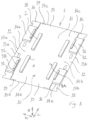
- a cardboard blank 1 is shown with eight shock-absorbing elements 2, 3 attached to an interior major surface 10.
- a first group of four shock-absorbing elements 2 are attached to a base section 11 of the cardboard blank and a second group of shock-absorbing elements 3 are attached to side sections 12 of the cardboard blank, two on each side section.
- One of the side sections 12 extends between a first edge 13a of the cardboard blank 1 and a first fold line 14a, and the other side section 12 extends between a second edge 13b of the cardboard blank and a second fold line 14b.
- a width direction W extends between the first edge 13a and the second edge 13b, a length direction L extending perpendicular to said width direction and parallel to at least one of said first and second edges, and a height direction H is perpendicular to the width direction and the length direction.
- Each of the shock-absorbing elements 2 of the first group are of an elongate rectangular configuration, arranged with its longer dimension extending in the length direction L, and is here made from a non-compressed honeycomb material.
- a pre-compressed honeycomb material or a combination of materials may, however, also be used for this purpose. It is also possible for the shock-absorbing elements 2 of the first group to have different shapes and/or sizes as long as they support the roof window and prevent damages to the pane, coverings, and/or claddings.
- Each of the shock-absorbing elements 3 of the second group are composed of two components, a larger component 31 being attached to the cardboard blank and being made of a non-compressed honeycomb material and a smaller component 32 being attached to the larger one and being made of a pre-compressed honeycomb material. It is, however, also possible for the shock-absorbing elements 3 of the second group to be made from one component only. In that case it is presently considered advantageous to use pre-compresses honeycomb, as the sides and corners of the frame of a roof window are particularly exposed if a packed roof window is dropped during handling or transportation.
- Each of the shock-absorbing elements 2 of the first group and each of the components 31, 32 of the shock-absorbing elements 3 of the second group are arranged with the height axis A of the material extending perpendicular to the interior major surface 10 of the cardboard blank.
- the shock-absorbing properties of the honeycomb material which is best in parallel to the height axis, will protect the roof windows from impacts perpendicular to the plane of the section of the cardboard blank to which the shock-absorbing element it attached. This applies independently of the size and shape of the shock-absorbing element.
- the cardboard blank 1 further comprises two end sections 15 and four corner sections 16 extending in continuation of the side sections 12.
- One of the end sections extends between a third edge 13c of the cardboard blank and a third fold line 14c and the other end section extends between a fourth edge 13d of the cardboard blank and a fourth fold line 14d, and further fold lines 14e are present between the side sections and the corner sections.
- the first fold line 14a, second fold line 14b, third fold line 14c, and fourth fold line 14d together delimit the base section 11 of the cardboard blank.
- Two openings 17a configured for serving as handles are shown on each side section 12 and two flaps 17b configured for being pushed into or out of the cardboard blank to form similar openings are shown on the base section 11. It is to be understood that such openings and/or flaps may also or alternatively be found at other positions on the cardboard blank.
- Each corner section 16 has a recess 18 and each end section 15 has two flaps 19, each formed by two slits extending from one of the third edge 13c and fourth edge 13d.
- these flaps 19 can be bent into the recesses 18 as shown in Fig. 2 , where corner sections 16 overlap with the end sections 15.
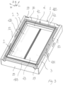
- the side sections 12 and end sections 15 have been folded along the fold lines 14a, 14b, 14c, 14d so that they extend in the height direction H and define an interior space I.
- side surfaces 311 of larger component 31 of the shock-absorbing elements 3 of the second group rest against the base section 11 and the smaller components 32 extend along the base section.
- the larger components 31 provide stability to the position of the side sections 12, and the smaller components 32 are configured for projecting underneath a frame 41 of a roof window 4 when arranged in the box formed by the folded cardboard blank as shown in Fig. 3 , thereby allowing them to engage with a sash 42 of the roof window.
- the engagement with sash is elastic. This allows the shock-absorbing elements 3 of the second group to support the sash 42, hindering movement in relation to the frame 41 in the width direction D, thereby reducing the risk of damages caused by collisions between the two and of damages to the hinges and locking assembly (not shown) of the roof window 4 during handling and transportation.
- the elasticity of the smaller components 32 allows them to engage with covering members (not shown) or other sensitive components on the sash without causing damages to these.
- the larger components 31 have height in the height direction, which is slightly larger than height of the roof window 4. This means that the larger components project slightly above the roof window, allowing them to support a lid (not shown) to be added to the box.
- the larger components 31 engage side frame members 411 of the frame 41 of the roof window, each extending over approximately one third of the length of the respective side frame member.
- the shock-absorbing elements 3 of the second group protects the corner of the roof window 4, which have been found to be at high risk of being damaged during handling and transportation of a packed roof window.
- the space between the shock-absorbing elements 3 of the second group remains open as also seen in Fig. 4 to facilitate use of the openings 17a as handles.
- the shock-absorbing elements 2 of the first group are seen through a pane 43 of the roof window 4.
- the pane rests on these shock-absorbing elements 2 and they are arranged such that they match the position of the corners of the pane, thereby engaging edges of the sash, such as covering members (not visible in the drawing).
- the shock-absorbing elements 2 of the first group may contribute to guiding the roof window 4 into the intended position within the box and to keeping it there.
- shock-absorbing elements 2 of the first group and the shock-absorbing elements 3 of the second group are arranged with a distance from each other matching the size and shape of the roof window 4 shown in Fig. 3 and Fig. 4 , it is to be understood that the same shock-absorbing elements may be used for other roof windows as well. If the roof window and hence also the base section 11 of the cardboard blank is bigger, the distance between the shock-absorbing elements can be increased, or a distance to the corners may be allowed. If the roof window and the base section are smaller, the distance between the shock-absorbing elements can be shortened, possibly even arranging them end to end, for example so that the shock-absorbing elements 2 of the first group form two continuous strips of shock-absorbing material.
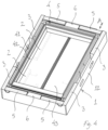
- Fig. 4 additional shock-absorbing elements 5, 6 have been arranged between the end sections 15 and the frame 41 of the roof window.
- these additional shock-absorbing elements are inserted from above and lie loose in the box, but it is within the scope of the invention to also attached these additional shock-absorbing elements to the cardboard blank.
- Such an attachment would require either attachment after folding or that the corner sections 16 are arranged to overlap the end sections 15 on the exterior side as opposed to on the interior side as seen in Fig. 3 .
- the additional shock-absorbing elements 5, 6 comprises two elongate end members 5 having a length corresponding to the length of top and bottom frame members 412, 413 of the roof window 4 as measured in the width direction W, and two boxes 6 containing items for use in the installation of the roof window 4, such as mounting brackets and screws.
- the elongate end members 5 are made from the same honeycomb material as the larger components 31 of the shock-absorbing elements 3 of the second group and arranged with the height axis of the material extending perpendicular to the interior surfaces of end sections 15, i.e. extending in the length direction L.
- the boxes 6 are made from cardboard by folding and arranged in recesses in the elongate end members 5.
Landscapes
- Engineering & Computer Science (AREA)
- Mechanical Engineering (AREA)
- Cartons (AREA)
- Buffer Packaging (AREA)
Abstract
Description
- The present invention relates to a method for packaging a roof window comprising A) providing a cardboard blank having an interior major surface adapted for facing the roof window, an exterior major surface opposite to the interior major surface, a first edge, a second edge opposite to said first edge, a width direction extending between the first edge and the second edge, a length direction extending perpendicular to said width direction and parallel to at least one of said first and second edges, and fold lines allowing the cardboard blank to be folded into a folded state defining an interior space, said fold lines delimiting two side sections extending along the first and second edges, respectively, and a base section located between the two side sections; B) arranging a plurality of shock-absorbing elements on the interior major surface of the cardboard blank; C) folding the cardboard blank along the fold lines so that the side sections come to extend in a height direction, which is perpendicular to the width direction and the length direction; and D) arranging a roof window on the base section so that it is in contact with at least some of the shock-absorbing elements. The invention further relates to a packed roof window.
- When transporting roof windows, it is vital to ensure that they are well protected. This may for example be ensured by packaging each roof window in a cardboard box and applying shock-absorbing elements at sensitive parts of the roof window. The shock-absorbing elements may prevent that excessive loads affect the roof window by cushioning the roof window and/or by preventing deformation of the cardboard box, and some shock-absorbing elements may serve to keep components of the roof window in their intended positions within the cardboard box. The shock-absorbing elements are usually arranged inside the cardboard box, either being attached to the roof window, for example by means of tape or staples, and/or being added as loose parts following the insertion of the roof window in the cardboard box. One example of a packed roof window, where these principles are used, is known from
WO2013/050041 . - While this method works very well there is a desire for an alternative packaging method that provides a higher degree of freedom in relation to several aspects of the packaging and unpacking process.
- It is therefore an object of the invention to provide an alternative method for packaging a roof window, which will still provide a good protection of the roof window during transportation, and a packed roof window obtained by such a method.
- In a first aspect of the invention this and further objects are achieved with a method for packaging a roof window as described in the introduction, which is further characterised in that, in step B), at least one of the shock-absorbing elements is attached to the cardboard blank, and that at least one of the shock-absorbing elements is made from a paper-based material and includes a honeycomb structure.
- By attaching the shock-absorbing elements to the cardboard blank, either before or after folding it into a box shape, the position of the shock-absorbing elements relative to the roof window can become more precise, and the risk of shock-absorbing elements being displaced from their intended position during handling and transportation of the packed roof window is considerably reduced or even eliminated. In addition, the risk of shock-absorbing elements being forgotten or misplaced by the operator at the packaging line is reduced.
- Another advantage of attaching the shock-absorbing elements to the cardboard blank is that the risk of glue residue being left on the roof window because of shock-absorbing elements having been attached to the roof window is reduced, and there is no need to use staples penetrating the frame of the roof window. In addition, the work of the installer becomes easier as it is no longer necessary to remove shock-absorbing elements from the roof window before commencing the installation process.
- Furthermore, by attaching the shock-absorbing elements to the cardboard blank, the packaging material can be handled as one piece, which is both helpful when packaging the roof window and when disposing the packaging material after use. This is particular the case since the shock-absorbing elements are now made from a paper-based material as opposed to expanded polystyrene (EPS), which has traditionally been used. With an all-paper packaging, everything belongs to the same recycling fraction and there is no need for separating the shock-absorbing elements from the cardboard blank. This increases the likelihood of the packaging material actually being recycled instead of just being disposed as combustible waste.
- Another potential advantage of using shock-absorbing elements made from a paper-based material is that they may be biologically degradable. Light-weight packaging element are easily caught by wind when installing a roof window on a roof of building and may easily end up in nature or other places where it cannot be collected by the installer. While it is of course not the intention to leave packaging material behind, a biodegradable packaging component does little harm.
- It is to be understood that while paper and cardboard are usually made from wood-fibres, other plant fibres including fibres originating from straw, bamboo, bagasse, esparto, other grasses, hemp, flax, and cotton may also be used, including combinations of different types of fibres. In Europe, up to 5% of alternative materials, such as the glue or adhesive, is acceptable, but a maximum of 3% is recommended.
- By including a honeycomb structure, the material consumption for the shock-absorbing elements is kept low, since a honeycomb structure has a comparatively high ratio between shock-absorbing property and weight.
- Honeycomb materials comprise an array of hollow cells, which are hexagonal in shape and columnar, being delimited by thin walls extending in a height axis of the material, and a cover layer may be provided on one or both sides to close the cells. Cell size typically vary between 8 mm and 30 mm, but in the prior art only honeycomb material with cell sizes of up to 20 mm have been considered suitable for packaging. The cell size is measured perpendicular to the height axis from the centre of one of the six sides of the hexagon to the centre of the opposite side.
- Honeycomb materials provide a combination of strength and deformability, which is comparable to that of EPS, and has therefore been found to be well suited for use between heavy products, such as a roof window, and the cardboard box, and/or for preventing a deformation of the cardboard box.
- A honeycomb material absorbs energy by deformation and should thus neither be so soft that it fully deforms nor so stiff that it does not deform. When used for packaging roof windows, this means that a differentiation of honeycomb quality and thickness may be needed to compensate for small-er/lighter windows creating less impact and thereby not deforming the honeycomb to same level as larger windows. A differentiation of the energy absorbing properties of the honeycomb material may be achieved by using different paper qualities for the formation of the cells, by using different paper qualities for the cover layer(s), by using different cell sizes, and/or or by using different cell heights.
- Two or more layers of honeycomb material may be arranged on top of each other and may be connected by an intermediate layer, which will typically be a sheet of paper or cardboard. The cell size may vary between layers. In one embodiment the cells of one layer have a diameter of 10 mm and the cells of the other layer have a diameter of 25 mm.
- Each cover layer and/or intermediate layer will typically be a sheet of paper or cardboard, typically having a weight of 100-200 g/m2.
- A layer of a honeycomb material typically has a height between 10 mm and 100 mm, and in multi-layer structures the layers may have different heights.
- In one embodiment, at least one of the shock-absorbing elements comprises a pre-compressed honeycomb structure. A pre-compressed honeycomb structure is to be understood as a honeycomb structure, which has been axially compressed in a direction parallel to the height axis of the material so that at least some of the walls delimiting the cells have collapsed. When an undeformed honeycomb material, hereafter also referred to as a non-compressed honeycomb structure, is exposed to axial loads higher than the compressive strength of the material, the result is a plastic deformation, which is substantially permanent. When a pre-compressed honeycomb structure is exposed to axial loads, it undergoes an elastic deformation due to the cell walls of the honeycomb structure having collapsed and assumed what may be described as a Z-shape. The use of a pre-compressed honeycomb structure thus provides elasticity to the shock-absorbing element. A shock-absorbing element may be composed of two or more components of which at least one is a pre-compressed honeycomb structure and at least one is a non-compressed honeycomb structure with intact cell walls.
- In one embodiment, step D) is performed before C), i.e. the roof window is arranged on the cardboard blank before it is folded. This allows that the roof window can be arranged from more than one angle and/or that different parts of the roof window can be arranged in different steps, thereby unlocking new degrees of freedom in the packaging process. As an example, the roof window may be arranged on the base section of the interior major surface and the two side sections together with two end sections may then be folded so that and upwards open box is formed around the roof window.
- Regardless of the sequence of the steps of the method, it may further comprise a step E) where a lid made from a separate cardboard blank is applied. Is this way a telescopic box may be formed. The use of a telescopic box may allow more freedom with respect to arranging other items into the box together with the roof window than what is the case with the seal end box shown in
WO2013/050041 . - In one embodiment, step B) is performed before step C), i.e. the shock-absorbing elements are attached to the cardboard blank before it is folded. This may provide a larger degree of freedom with respect to the shape and size of the shock-absorbing elements and/or to the positions in which the shock-absorbing elements can be arranged, and, if step D) is performed before step C), folding of the cardboard blank may result in shock-absorbing elements or parts therefore being swung into contact with the roof window. As an example, shock-absorbing elements provided on the side sections may be swung into contact with a frame of the roof window, and this may potentially result in part of the shock-absorbing elements entering into grooves or recesses in the frame.
- Regardless of the sequence of the steps of the method, at least one shock-absorbing element is preferably arranged to be in contact with at least one component of the roof window chosen from the group consisting of: a frame, a sash, a pane, a covering, a cladding, a handle, a hinge, an insulating element, an electric operator, an electronic component, a rain sensor, and a photovoltaic element.
- In one embodiment, the shock-absorbing elements are shaped and/or attached in positions allowing the packaging of at least two different types and/or sizes of the roof window. As an example, four shock-absorbing elements, which are arranged on the base section and intended to come into contact with a pane of the roof window in the packed state, may be arranged so that they become located one at each corner of the pane when packaging a smaller roof window and so that they become located further towards the centre of the pane when packaging a larger roof window. As another example, such four shock-absorbing elements may have an elongate shape and be function as four separate elements when packaging a larger roof window but abutting each other forming two continuous strips of shock-absorbing material when packaging a smaller roof window. Similar considerations apply to shock-absorbing elements attached to the side sections, to end sections extending between the side sections, and to a lid.
- In one embodiment, the cardboard blank comprises compressed sections, slits and/or recesses facilitating folding and/or assembly into a box shape.
- A compressed section may be for example be an embossed line serving as a fold line. In this context it is noted that while the fold lines do not need to be physical lines, it is presently considered advantageous.
- A slit may for example separate an end section from a side section and define a corner section, attached to one of the side section and the end section and overlapping with the other in the folded state. One or more slits may also or alternatively define a locking tab configured for being folded into a recess for locking two sections of the cardboard blank in relation to each other, thereby keeping the cardboard blank in a folded state. A recess may also or alternatively be configured for serving as a handle for use when handling the packed roof window.
- In a second aspect of the invention the object is achieved with a packed roof window, where the roof window is arranged in a box formed by folding a cardboard blank and having an interior space, said cardboard blank having an interior major surface facing the roof window, an exterior major surface opposite to the interior major surface, a first edge, a second edge opposite to said first edge, a width direction extending between the first edge and the second edge, a length direction extending perpendicular to said width direction and parallel to at least one of said first and second edges, and said cardboard blank being folded along fold lines so that two side sections of the cardboard blank are perpendicular to the width direction and the length direction and extend in a height direction, where the roof window is arranged on a base section located between the two side sections, and where a plurality of shock-absorbing elements are arranged between the interior major surface of the cardboard blank and the roof window, so that the roof window is in contact with at least some of the shock-absorbing elements, wherein at least one of the shock-absorbing elements is attached to the cardboard blank, and at least one of the shock-absorbing elements is made from a paper-based material and includes a honeycomb structure.
- Embodiments and advantages described with reference to the first aspect of the invention also applies to the second aspect of the invention and vice versa, unless otherwise stated.
- In the following description, embodiments of the invention will be described with reference to the schematic drawings, in which
-
Fig. 1 is a perspective view of a cardboard blank with shock-absorbing elements attached thereto, -
Fig. 2 shows the cardboard blank inFig. 1 in a folded state, -
Fig. 3 corresponds toFig. 2 but with a roof window arranged on a base section of the cardboard blank, and -
Fig. 4 corresponds toFig. 3 but with further shock-absorbing elements arranged between the roof window and the cardboard blank. - Referring initially to
Fig. 1 acardboard blank 1 is shown with eight shock-absorbingelements major surface 10. A first group of four shock-absorbingelements 2 are attached to abase section 11 of the cardboard blank and a second group of shock-absorbingelements 3 are attached toside sections 12 of the cardboard blank, two on each side section. - One of the
side sections 12 extends between a first edge 13a of thecardboard blank 1 and a first fold line 14a, and theother side section 12 extends between a second edge 13b of the cardboard blank and a second fold line 14b. - A width direction W extends between the first edge 13a and the second edge 13b, a length direction L extending perpendicular to said width direction and parallel to at least one of said first and second edges, and a height direction H is perpendicular to the width direction and the length direction.
- Each of the shock-absorbing
elements 2 of the first group are of an elongate rectangular configuration, arranged with its longer dimension extending in the length direction L, and is here made from a non-compressed honeycomb material. A pre-compressed honeycomb material or a combination of materials may, however, also be used for this purpose. It is also possible for the shock-absorbingelements 2 of the first group to have different shapes and/or sizes as long as they support the roof window and prevent damages to the pane, coverings, and/or claddings. - Each of the shock-absorbing
elements 3 of the second group are composed of two components, alarger component 31 being attached to the cardboard blank and being made of a non-compressed honeycomb material and asmaller component 32 being attached to the larger one and being made of a pre-compressed honeycomb material. It is, however, also possible for the shock-absorbingelements 3 of the second group to be made from one component only. In that case it is presently considered advantageous to use pre-compresses honeycomb, as the sides and corners of the frame of a roof window are particularly exposed if a packed roof window is dropped during handling or transportation. - Each of the shock-absorbing
elements 2 of the first group and each of thecomponents elements 3 of the second group are arranged with the height axis A of the material extending perpendicular to the interiormajor surface 10 of the cardboard blank. In this way the shock-absorbing properties of the honeycomb material, which is best in parallel to the height axis, will protect the roof windows from impacts perpendicular to the plane of the section of the cardboard blank to which the shock-absorbing element it attached. This applies independently of the size and shape of the shock-absorbing element. - The
cardboard blank 1 further comprises twoend sections 15 and fourcorner sections 16 extending in continuation of theside sections 12. One of the end sections extends between a third edge 13c of the cardboard blank and athird fold line 14c and the other end section extends between afourth edge 13d of the cardboard blank and afourth fold line 14d, andfurther fold lines 14e are present between the side sections and the corner sections. - The first fold line 14a, second fold line 14b,
third fold line 14c, andfourth fold line 14d together delimit thebase section 11 of the cardboard blank. - Two
openings 17a configured for serving as handles are shown on eachside section 12 and two flaps 17b configured for being pushed into or out of the cardboard blank to form similar openings are shown on thebase section 11. It is to be understood that such openings and/or flaps may also or alternatively be found at other positions on the cardboard blank. - Each
corner section 16 has arecess 18 and eachend section 15 has twoflaps 19, each formed by two slits extending from one of the third edge 13c andfourth edge 13d. For keeping the cardboard blank in a folded state, where it forms a box, theseflaps 19 can be bent into therecesses 18 as shown inFig. 2 , wherecorner sections 16 overlap with theend sections 15. - In the folded state shown in
Fig. 2 , theside sections 12 andend sections 15 have been folded along thefold lines larger component 31 of the shock-absorbingelements 3 of the second group (seen inFig. 1 ) rest against thebase section 11 and thesmaller components 32 extend along the base section. In this way, thelarger components 31 provide stability to the position of theside sections 12, and thesmaller components 32 are configured for projecting underneath aframe 41 of aroof window 4 when arranged in the box formed by the folded cardboard blank as shown inFig. 3 , thereby allowing them to engage with asash 42 of the roof window. As thesmaller components 32 are made of a pre-compressed honeycomb material and arranged with the height axis of the material extending perpendicular to the interior surfaces ofside sections 12, i.e. extending in the width direction W, the engagement with sash is elastic. This allows the shock-absorbingelements 3 of the second group to support thesash 42, hindering movement in relation to theframe 41 in the width direction D, thereby reducing the risk of damages caused by collisions between the two and of damages to the hinges and locking assembly (not shown) of theroof window 4 during handling and transportation. The elasticity of thesmaller components 32 allows them to engage with covering members (not shown) or other sensitive components on the sash without causing damages to these. - As seen in
Fig. 3 , thelarger components 31 have height in the height direction, which is slightly larger than height of theroof window 4. This means that the larger components project slightly above the roof window, allowing them to support a lid (not shown) to be added to the box. - Furthermore, the
larger components 31 engageside frame members 411 of theframe 41 of the roof window, each extending over approximately one third of the length of the respective side frame member. In this way the shock-absorbingelements 3 of the second group protects the corner of theroof window 4, which have been found to be at high risk of being damaged during handling and transportation of a packed roof window. In this embodiment, the space between the shock-absorbingelements 3 of the second group remains open as also seen inFig. 4 to facilitate use of theopenings 17a as handles. - Both in
Fig. 3 and inFig. 4 the shock-absorbingelements 2 of the first group are seen through apane 43 of theroof window 4. The pane rests on these shock-absorbingelements 2 and they are arranged such that they match the position of the corners of the pane, thereby engaging edges of the sash, such as covering members (not visible in the drawing). In this way the shock-absorbingelements 2 of the first group may contribute to guiding theroof window 4 into the intended position within the box and to keeping it there. - While both the shock-absorbing
elements 2 of the first group and the shock-absorbingelements 3 of the second group are arranged with a distance from each other matching the size and shape of theroof window 4 shown inFig. 3 andFig. 4 , it is to be understood that the same shock-absorbing elements may be used for other roof windows as well. If the roof window and hence also thebase section 11 of the cardboard blank is bigger, the distance between the shock-absorbing elements can be increased, or a distance to the corners may be allowed. If the roof window and the base section are smaller, the distance between the shock-absorbing elements can be shortened, possibly even arranging them end to end, for example so that the shock-absorbingelements 2 of the first group form two continuous strips of shock-absorbing material. - In
Fig. 4 additional shock-absorbingelements end sections 15 and theframe 41 of the roof window. In this embodiment these additional shock-absorbing elements are inserted from above and lie loose in the box, but it is within the scope of the invention to also attached these additional shock-absorbing elements to the cardboard blank. Such an attachment would require either attachment after folding or that thecorner sections 16 are arranged to overlap theend sections 15 on the exterior side as opposed to on the interior side as seen inFig. 3 . - In the embodiment in
Fig. 4 the additional shock-absorbingelements elongate end members 5 having a length corresponding to the length of top andbottom frame members roof window 4 as measured in the width direction W, and twoboxes 6 containing items for use in the installation of theroof window 4, such as mounting brackets and screws. Theelongate end members 5 are made from the same honeycomb material as thelarger components 31 of the shock-absorbingelements 3 of the second group and arranged with the height axis of the material extending perpendicular to the interior surfaces ofend sections 15, i.e. extending in the length direction L. Theboxes 6 are made from cardboard by folding and arranged in recesses in theelongate end members 5. It would, however, also be possible to use four separate end members in the same way as the four shock-absorbingelements 3 of the second group and then arrange the boxes between them, or the boxes could be left out, possibly using elongate end members without recesses, or leaving a space between separate end members open. -
- 1
- Cardboard blank
- 10
- Interior major surface
- 11
- Base section
- 12
- Side section
- 13
- Edge
- 14
- Fold line
- 15
- End section
- 16
- Corner section
- 17a
- Opening
- 17b
- Flap
- 18
- Recess
- 19
- Flap
- 2
- Shock-absorbing element
- 3
- Shock-absorbing element
- 31
- Larger component
- 311
- Side surface
- 32
- Smaller component
- 4
- Roof window
- 41
- Frame
- 411
- Side frame members
- 412
- Top frame member
- 413
- Bottom frame member
- 42
- Sash
- 43
- Pane
- 5
- Additional shock-absorbing element
- 6
- Additional shock-absorbing element
- A
- Height axis
- H
- Height direction
- I
- Interior space
- L
- Length direction
- W
- Width direction
Claims (10)
- A method for packaging a roof window (4) comprisingA) providing a cardboard blank (1) having an interior major surface (10) adapted for facing the roof window (4), an exterior major surface opposite to the interior major surface (10), a first edge (13a), a second edge (13b) opposite to said first edge (13a), a width direction (W) extending between the first edge (13a) and the second edge (13b), a length direction (L) extending perpendicular to said width direction (W) and parallel to at least one of said first and second edges (13, 13a, 13b), and fold lines (14) allowing the cardboard blank (1) to be folded into a folded state defining an interior space (I), said fold lines (14) delimiting two side sections (12) extending along the first and second edges (13a, 13b), respectively, and a base section (11) located between the two side sections (12),B) arranging a plurality of shock-absorbing elements (2, 3) on the interior major surface (10) of the cardboard blank (1),C) folding the cardboard blank (1) along the fold lines (14) so that the side sections (12) come to extend in a height direction (H), which is perpendicular to the width direction (W) and the length direction (L), andD) arranging a roof window (4) on the base section (11) so that it is in contact with at least some of the shock-absorbing elements (2, 3),characterised in that
in step B), at least one of the shock-absorbing elements (2, 3) is attached to the cardboard blank (1), and that at least one of the shock-absorbing elements (2, 3) is made from a paper-based material and includes a honeycomb structure. - A method according to claim 1, wherein at least one of the shock-absorbing elements (2, 3) comprises a pre-compressed honeycomb structure.
- A method according to one or more of the preceding claims, wherein at least one shock-absorbing element (2, 3) is composed of two or more components of which at least one is a pre-compressed honeycomb structure and at least one is a non-compressed honeycomb structure.
- A method according to one or more of the preceding claims, wherein step D) is performed before step C).
- A method according to one or more of the preceding claims, wherein step B) is performed before step C).
- A method according to one or more of the preceding claims, wherein at least one shock-absorbing element (2, 3) is arranged to be in contact with at least one component of the roof window (4) chosen from the group consisting of: a frame (41), a sash (42), a pane (43), a covering, a cladding, a handle, a hinge, an insulating element, an electric operator, an electronic component, a rain sensor, and a photovoltaic element.
- A method according to one or more of the preceding claims, wherein the shock-absorbing elements (2, 3) are shaped and/or attached in positions allowing the packaging of at least two different types and/or sizes of the roof window (4).
- A method according to one or more of the preceding claims, wherein the cardboard blank (1) comprises compressed sections, slits and/or recesses (18) facilitating folding and/or assembly into a box shape.
- A method according to one or more of the preceding claims, further comprising a step E) where a lid made from a separate cardboard blank is applied.
- A packed roof window (4), where the roof window (4) is arranged in a box formed by folding a cardboard blank (1) and having an interior space (I), said cardboard blank (1) having an interior major surface (10) facing the roof window (4), an exterior major surface opposite to the interior major surface (10), a first edge (13a), a second edge (13b) opposite to said first edge (13a), a width direction (W) extending between the first edge (13a) and the second edge (13b), a length direction (L) extending perpendicular to said width direction (W) and parallel to at least one of said first and second edges (13a, 13b), and said cardboard blank (1) being folded along fold lines (14) so that two side sections (12) of the cardboard blank (1) are perpendicular to the width direction (W) and the length direction (L) and extend in a height direction (H), where the roof window (4) is arranged on a base section (11) located between the two side sections (12), and where a plurality of shock-absorbing elements (2, 3) are arranged between the interior major surface (10) of the cardboard blank (1) and the roof window (4), so that the roof window (4) is in contact with at least some of the shock-absorbing elements (2,3),
characterised in that
at least one of the shock-absorbing elements (2, 3) is attached to the cardboard blank (1), and that at least one of the shock-absorbing elements (2, 3) is made from a paper-based material and includes a honeycomb structure.
Applications Claiming Priority (1)
| Application Number | Priority Date | Filing Date | Title |
|---|---|---|---|
| DKPA202270548A DK181617B1 (en) | 2022-11-11 | 2022-11-11 | A method for packaging a roof window and a packed roof window |
Publications (1)
| Publication Number | Publication Date |
|---|---|
| EP4368530A1 true EP4368530A1 (en) | 2024-05-15 |
Family
ID=90624957
Family Applications (1)
| Application Number | Title | Priority Date | Filing Date |
|---|---|---|---|
| EP23207855.0A Pending EP4368530A1 (en) | 2022-11-11 | 2023-11-06 | A method for packaging a roof window and a packed roof window |
Country Status (2)
| Country | Link |
|---|---|
| EP (1) | EP4368530A1 (en) |
| DK (1) | DK181617B1 (en) |
Citations (6)
| Publication number | Priority date | Publication date | Assignee | Title |
|---|---|---|---|---|
| US1792627A (en) * | 1928-10-20 | 1931-02-17 | Rochester Folding Box Company | Packing case |
| US5040696A (en) * | 1990-04-16 | 1991-08-20 | Shippers Paper Products Company | Extended length packaging |
| WO2013050041A1 (en) | 2011-10-04 | 2013-04-11 | Vkr Holding A/S | A packaging for a window and a method for packing |
| US8752703B2 (en) * | 2009-03-18 | 2014-06-17 | Third Dimension, Inc. | Packaging system and method |
| EP2590873B1 (en) * | 2010-07-09 | 2014-09-03 | SCA Packaging Hungary Kft | Dual-purpose packaging insert and packaging box for sensitive flat objects |
| EP4089025A2 (en) * | 2021-05-12 | 2022-11-16 | VKR Holding A/S | A packed roof window |
Family Cites Families (4)
| Publication number | Priority date | Publication date | Assignee | Title |
|---|---|---|---|---|
| DK200500501A (en) * | 2005-04-08 | 2006-10-09 | Vkr Holding As | Method, retaining member and packaging for packaging a product comprising a plurality of sub-components |
| DK201570503A1 (en) * | 2015-08-04 | 2017-02-27 | Vkr Holding As | Method for packaging a window with frame insulation and a packed window |
| DK202070161A1 (en) * | 2020-03-10 | 2021-10-29 | Vkr Holding As | A packaging for installation elements for a roof window, a packed kit of installation elements, and method of providing a packaging for roof window installation elements |
| DE202022102573U1 (en) * | 2021-05-12 | 2022-09-06 | Vkr Holding A/S | Packaging for a kit comprising installation assemblies for a skylight system |
-
2022
- 2022-11-11 DK DKPA202270548A patent/DK181617B1/en active IP Right Grant
-
2023
- 2023-11-06 EP EP23207855.0A patent/EP4368530A1/en active Pending
Patent Citations (6)
| Publication number | Priority date | Publication date | Assignee | Title |
|---|---|---|---|---|
| US1792627A (en) * | 1928-10-20 | 1931-02-17 | Rochester Folding Box Company | Packing case |
| US5040696A (en) * | 1990-04-16 | 1991-08-20 | Shippers Paper Products Company | Extended length packaging |
| US8752703B2 (en) * | 2009-03-18 | 2014-06-17 | Third Dimension, Inc. | Packaging system and method |
| EP2590873B1 (en) * | 2010-07-09 | 2014-09-03 | SCA Packaging Hungary Kft | Dual-purpose packaging insert and packaging box for sensitive flat objects |
| WO2013050041A1 (en) | 2011-10-04 | 2013-04-11 | Vkr Holding A/S | A packaging for a window and a method for packing |
| EP4089025A2 (en) * | 2021-05-12 | 2022-11-16 | VKR Holding A/S | A packed roof window |
Also Published As
| Publication number | Publication date |
|---|---|
| DK202270548A1 (en) | 2024-07-02 |
| DK181617B1 (en) | 2024-07-02 |
Similar Documents
| Publication | Publication Date | Title |
|---|---|---|
| US3734389A (en) | Package corner post | |
| EP4089025B1 (en) | A packed roof window | |
| US12428193B2 (en) | Packed roof window products | |
| US6539880B2 (en) | Corrugated paperboard pallet rail | |
| US20200385191A1 (en) | Product packaging system | |
| EP4091959A1 (en) | A packed roof window, a ventilation flap retainer, and use of a ventilation flap retainer | |
| EP4412922B1 (en) | Packed roof window product, a method for packing a packed roof window product, and a method of unpacking a packed roof window product | |
| EP2590873A1 (en) | Dual-purpose packaging insert and packaging box for sensitive flat objects | |
| DK181617B1 (en) | A method for packaging a roof window and a packed roof window | |
| DE202022102578U1 (en) | Wrapped skylight | |
| EP4089022A2 (en) | Packed roof window product | |
| EP4089034B1 (en) | Packed installation kit comprising installation assemblies for a roof window system | |
| US5702053A (en) | Composite insulator-packing container and a method for packing a composite insulator | |
| EP4412913B1 (en) | Packed roof window product | |
| EP4089023B1 (en) | A packed roof window product | |
| EP0937649A1 (en) | Cardboard box | |
| EP4212446A1 (en) | A holding element for use in packaging a product, a packaging, a method for making a holding element, and a method for packaging a product | |
| EP4089031B1 (en) | Packed installation kit comprising an installation assembly with support beams as components | |
| US20260048894A1 (en) | Blank configured to be erected into a package and a package formed by such a blank | |
| CN224061420U (en) | Hexagonal handle safety buckle mortise lock box | |
| CN222973861U (en) | Hidden packing box for control cabinet handle | |
| EP3865416B1 (en) | Pallet, support foot and methods for producing a pallet | |
| DK181313B1 (en) | Packed roof window products | |
| EP4029807A2 (en) | Insert element for an internal packaging, internal packaging and packaging unit | |
| JP2002087433A (en) | Product transport pallet |
Legal Events
| Date | Code | Title | Description |
|---|---|---|---|
| PUAI | Public reference made under article 153(3) epc to a published international application that has entered the european phase |
Free format text: ORIGINAL CODE: 0009012 |
|
| STAA | Information on the status of an ep patent application or granted ep patent |
Free format text: STATUS: THE APPLICATION HAS BEEN PUBLISHED |
|
| AK | Designated contracting states |
Kind code of ref document: A1 Designated state(s): AL AT BE BG CH CY CZ DE DK EE ES FI FR GB GR HR HU IE IS IT LI LT LU LV MC ME MK MT NL NO PL PT RO RS SE SI SK SM TR |
|
| STAA | Information on the status of an ep patent application or granted ep patent |
Free format text: STATUS: REQUEST FOR EXAMINATION WAS MADE |
|
| 17P | Request for examination filed |
Effective date: 20241113 |
|
| RBV | Designated contracting states (corrected) |
Designated state(s): AL AT BE BG CH CY CZ DE DK EE ES FI FR GB GR HR HU IE IS IT LI LT LU LV MC ME MK MT NL NO PL PT RO RS SE SI SK SM TR |