EP4368458A2 - Electrical power supply device and method of operating same - Google Patents
Electrical power supply device and method of operating same Download PDFInfo
- Publication number
- EP4368458A2 EP4368458A2 EP24166900.1A EP24166900A EP4368458A2 EP 4368458 A2 EP4368458 A2 EP 4368458A2 EP 24166900 A EP24166900 A EP 24166900A EP 4368458 A2 EP4368458 A2 EP 4368458A2
- Authority
- EP
- European Patent Office
- Prior art keywords
- voltage
- output voltage
- device controller
- output
- input voltage
- Prior art date
- Legal status (The legal status is an assumption and is not a legal conclusion. Google has not performed a legal analysis and makes no representation as to the accuracy of the status listed.)
- Pending
Links
Images
Classifications
-
- H—ELECTRICITY
- H02—GENERATION; CONVERSION OR DISTRIBUTION OF ELECTRIC POWER
- H02M—APPARATUS FOR CONVERSION BETWEEN AC AND AC, BETWEEN AC AND DC, OR BETWEEN DC AND DC, AND FOR USE WITH MAINS OR SIMILAR POWER SUPPLY SYSTEMS; CONVERSION OF DC OR AC INPUT POWER INTO SURGE OUTPUT POWER; CONTROL OR REGULATION THEREOF
- H02M1/00—Details of apparatus for conversion
- H02M1/36—Means for starting or stopping converters
-
- B—PERFORMING OPERATIONS; TRANSPORTING
- B60—VEHICLES IN GENERAL
- B60R—VEHICLES, VEHICLE FITTINGS, OR VEHICLE PARTS, NOT OTHERWISE PROVIDED FOR
- B60R16/00—Electric or fluid circuits specially adapted for vehicles and not otherwise provided for; Arrangement of elements of electric or fluid circuits specially adapted for vehicles and not otherwise provided for
- B60R16/02—Electric or fluid circuits specially adapted for vehicles and not otherwise provided for; Arrangement of elements of electric or fluid circuits specially adapted for vehicles and not otherwise provided for electric constitutive elements
- B60R16/03—Electric or fluid circuits specially adapted for vehicles and not otherwise provided for; Arrangement of elements of electric or fluid circuits specially adapted for vehicles and not otherwise provided for electric constitutive elements for supply of electrical power to vehicle subsystems or for
-
- G—PHYSICS
- G06—COMPUTING OR CALCULATING; COUNTING
- G06F—ELECTRIC DIGITAL DATA PROCESSING
- G06F1/00—Details not covered by groups G06F3/00 - G06F13/00 and G06F21/00
- G06F1/26—Power supply means, e.g. regulation thereof
- G06F1/266—Arrangements to supply power to external peripherals either directly from the computer or under computer control, e.g. supply of power through the communication port, computer controlled power-strips
-
- H—ELECTRICITY
- H02—GENERATION; CONVERSION OR DISTRIBUTION OF ELECTRIC POWER
- H02J—ELECTRIC POWER NETWORKS; CIRCUIT ARRANGEMENTS OR SYSTEMS FOR SUPPLYING OR DISTRIBUTING ELECTRIC POWER; SYSTEMS FOR STORING ELECTRIC ENERGY
- H02J7/00—Circuit arrangements for charging or discharging batteries or for supplying loads from batteries
- H02J7/14—Circuit arrangements for charging or discharging batteries or for supplying loads from batteries for charging batteries from dynamo-electric generators driven at varying speed, e.g. on vehicle
- H02J7/1446—Circuit arrangements for charging or discharging batteries or for supplying loads from batteries for charging batteries from dynamo-electric generators driven at varying speed, e.g. on vehicle in response to parameters of a vehicle
-
- B—PERFORMING OPERATIONS; TRANSPORTING
- B60—VEHICLES IN GENERAL
- B60R—VEHICLES, VEHICLE FITTINGS, OR VEHICLE PARTS, NOT OTHERWISE PROVIDED FOR
- B60R16/00—Electric or fluid circuits specially adapted for vehicles and not otherwise provided for; Arrangement of elements of electric or fluid circuits specially adapted for vehicles and not otherwise provided for
- B60R16/02—Electric or fluid circuits specially adapted for vehicles and not otherwise provided for; Arrangement of elements of electric or fluid circuits specially adapted for vehicles and not otherwise provided for electric constitutive elements
- B60R16/023—Electric or fluid circuits specially adapted for vehicles and not otherwise provided for; Arrangement of elements of electric or fluid circuits specially adapted for vehicles and not otherwise provided for electric constitutive elements for transmission of signals between vehicle parts or subsystems
-
- G—PHYSICS
- G05—CONTROLLING; REGULATING
- G05B—CONTROL OR REGULATING SYSTEMS IN GENERAL; FUNCTIONAL ELEMENTS OF SUCH SYSTEMS; MONITORING OR TESTING ARRANGEMENTS FOR SUCH SYSTEMS OR ELEMENTS
- G05B15/00—Systems controlled by a computer
- G05B15/02—Systems controlled by a computer electric
-
- H—ELECTRICITY
- H02—GENERATION; CONVERSION OR DISTRIBUTION OF ELECTRIC POWER
- H02J—ELECTRIC POWER NETWORKS; CIRCUIT ARRANGEMENTS OR SYSTEMS FOR SUPPLYING OR DISTRIBUTING ELECTRIC POWER; SYSTEMS FOR STORING ELECTRIC ENERGY
- H02J7/00—Circuit arrangements for charging or discharging batteries or for supplying loads from batteries
- H02J7/60—Circuit arrangements for charging or discharging batteries or for supplying loads from batteries including safety or protection arrangements
- H02J7/68—Circuit arrangements for charging or discharging batteries or for supplying loads from batteries including safety or protection arrangements using circuits for correcting or protecting against reverse-polarity
-
- H—ELECTRICITY
- H02—GENERATION; CONVERSION OR DISTRIBUTION OF ELECTRIC POWER
- H02M—APPARATUS FOR CONVERSION BETWEEN AC AND AC, BETWEEN AC AND DC, OR BETWEEN DC AND DC, AND FOR USE WITH MAINS OR SIMILAR POWER SUPPLY SYSTEMS; CONVERSION OF DC OR AC INPUT POWER INTO SURGE OUTPUT POWER; CONTROL OR REGULATION THEREOF
- H02M3/00—Conversion of DC power input into DC power output
-
- H—ELECTRICITY
- H02—GENERATION; CONVERSION OR DISTRIBUTION OF ELECTRIC POWER
- H02M—APPARATUS FOR CONVERSION BETWEEN AC AND AC, BETWEEN AC AND DC, OR BETWEEN DC AND DC, AND FOR USE WITH MAINS OR SIMILAR POWER SUPPLY SYSTEMS; CONVERSION OF DC OR AC INPUT POWER INTO SURGE OUTPUT POWER; CONTROL OR REGULATION THEREOF
- H02M3/00—Conversion of DC power input into DC power output
- H02M3/02—Conversion of DC power input into DC power output without intermediate conversion into AC
- H02M3/04—Conversion of DC power input into DC power output without intermediate conversion into AC by static converters
- H02M3/10—Conversion of DC power input into DC power output without intermediate conversion into AC by static converters using discharge tubes with control electrode or semiconductor devices with control electrode
- H02M3/145—Conversion of DC power input into DC power output without intermediate conversion into AC by static converters using discharge tubes with control electrode or semiconductor devices with control electrode using devices of a triode or transistor type requiring continuous application of a control signal
- H02M3/155—Conversion of DC power input into DC power output without intermediate conversion into AC by static converters using discharge tubes with control electrode or semiconductor devices with control electrode using devices of a triode or transistor type requiring continuous application of a control signal using semiconductor devices only
- H02M3/156—Conversion of DC power input into DC power output without intermediate conversion into AC by static converters using discharge tubes with control electrode or semiconductor devices with control electrode using devices of a triode or transistor type requiring continuous application of a control signal using semiconductor devices only with automatic control of output voltage or current, e.g. switching regulators
- H02M3/158—Conversion of DC power input into DC power output without intermediate conversion into AC by static converters using discharge tubes with control electrode or semiconductor devices with control electrode using devices of a triode or transistor type requiring continuous application of a control signal using semiconductor devices only with automatic control of output voltage or current, e.g. switching regulators including plural semiconductor devices as final control devices for a single load
- H02M3/1582—Buck-boost converters
-
- H—ELECTRICITY
- H04—ELECTRIC COMMUNICATION TECHNIQUE
- H04L—TRANSMISSION OF DIGITAL INFORMATION, e.g. TELEGRAPHIC COMMUNICATION
- H04L12/00—Data switching networks
- H04L12/28—Data switching networks characterised by path configuration, e.g. LAN [Local Area Networks] or WAN [Wide Area Networks]
- H04L12/40—Bus networks
- H04L12/40006—Architecture of a communication node
- H04L12/40045—Details regarding the feeding of energy to the node from the bus
-
- H—ELECTRICITY
- H02—GENERATION; CONVERSION OR DISTRIBUTION OF ELECTRIC POWER
- H02J—ELECTRIC POWER NETWORKS; CIRCUIT ARRANGEMENTS OR SYSTEMS FOR SUPPLYING OR DISTRIBUTING ELECTRIC POWER; SYSTEMS FOR STORING ELECTRIC ENERGY
- H02J2105/00—Networks for supplying or distributing electric power characterised by their spatial reach or by the load
- H02J2105/30—Networks for supplying or distributing electric power characterised by their spatial reach or by the load the load networks being external to vehicles, i.e. exchanging power with vehicles
- H02J2105/33—Networks for supplying or distributing electric power characterised by their spatial reach or by the load the load networks being external to vehicles, i.e. exchanging power with vehicles exchanging power with road vehicles
-
- H—ELECTRICITY
- H02—GENERATION; CONVERSION OR DISTRIBUTION OF ELECTRIC POWER
- H02J—ELECTRIC POWER NETWORKS; CIRCUIT ARRANGEMENTS OR SYSTEMS FOR SUPPLYING OR DISTRIBUTING ELECTRIC POWER; SYSTEMS FOR STORING ELECTRIC ENERGY
- H02J7/00—Circuit arrangements for charging or discharging batteries or for supplying loads from batteries
- H02J7/40—Circuit arrangements for charging or discharging batteries or for supplying loads from batteries characterised by the exchange of charge or discharge related data
- H02J7/42—Circuit arrangements for charging or discharging batteries or for supplying loads from batteries characterised by the exchange of charge or discharge related data with electronic devices having internal batteries, e.g. mobile phones
-
- H—ELECTRICITY
- H04—ELECTRIC COMMUNICATION TECHNIQUE
- H04L—TRANSMISSION OF DIGITAL INFORMATION, e.g. TELEGRAPHIC COMMUNICATION
- H04L12/00—Data switching networks
- H04L12/28—Data switching networks characterised by path configuration, e.g. LAN [Local Area Networks] or WAN [Wide Area Networks]
- H04L12/40—Bus networks
- H04L2012/40208—Bus networks characterized by the use of a particular bus standard
- H04L2012/40215—Controller Area Network CAN
-
- H—ELECTRICITY
- H04—ELECTRIC COMMUNICATION TECHNIQUE
- H04L—TRANSMISSION OF DIGITAL INFORMATION, e.g. TELEGRAPHIC COMMUNICATION
- H04L12/00—Data switching networks
- H04L12/28—Data switching networks characterised by path configuration, e.g. LAN [Local Area Networks] or WAN [Wide Area Networks]
- H04L12/40—Bus networks
- H04L2012/40208—Bus networks characterized by the use of a particular bus standard
- H04L2012/40234—Local Interconnect Network LIN
-
- H—ELECTRICITY
- H04—ELECTRIC COMMUNICATION TECHNIQUE
- H04L—TRANSMISSION OF DIGITAL INFORMATION, e.g. TELEGRAPHIC COMMUNICATION
- H04L12/00—Data switching networks
- H04L12/28—Data switching networks characterised by path configuration, e.g. LAN [Local Area Networks] or WAN [Wide Area Networks]
- H04L12/40—Bus networks
- H04L2012/40267—Bus for use in transportation systems
- H04L2012/40273—Bus for use in transportation systems the transportation system being a vehicle
-
- Y—GENERAL TAGGING OF NEW TECHNOLOGICAL DEVELOPMENTS; GENERAL TAGGING OF CROSS-SECTIONAL TECHNOLOGIES SPANNING OVER SEVERAL SECTIONS OF THE IPC; TECHNICAL SUBJECTS COVERED BY FORMER USPC CROSS-REFERENCE ART COLLECTIONS [XRACs] AND DIGESTS
- Y02—TECHNOLOGIES OR APPLICATIONS FOR MITIGATION OR ADAPTATION AGAINST CLIMATE CHANGE
- Y02T—CLIMATE CHANGE MITIGATION TECHNOLOGIES RELATED TO TRANSPORTATION
- Y02T10/00—Road transport of goods or passengers
- Y02T10/60—Other road transportation technologies with climate change mitigation effect
- Y02T10/72—Electric energy management in electromobility
Definitions
- the invention generally relates to an electrical power supply device and method of operating the electrical power supply device.
- USB Universal Serial Bus
- USB has become a ubiquitous power socket for many consumer devices such as cellular telephones, digital media players and/or other hand-held devices.
- Users utilize USB to fulfil their requirements not only in terms of data but also to provide power to, or charge, their devices simply, often without the need to load a driver, in order to carry out "traditional" USB functions.
- USB Power Delivery (PD) Specification enables the maximum functionality of USB by providing more flexible power delivery, e.g., for battery charging, along with data over a single cable. Its aim is to operate with and build on the existing USB ecosystem.
- the USB Power Delivery Specification 3.0 is published by the USB Implementer's Forum, Inc and is incorporated by reference herein.
- USB PD device has imposed requirements for a USB PD device and other automotive electrical modules powered by the vehicle battery requires it to meet "Start/Stop" transient tests in which the vehicle battery voltage temporarily dips down to as low as 6 volts to simulate the vehicle cranking during a warm start. During this transient, the USB PD device is expected to continue to function with no disruption to the consumer experience. With only a 6 volt input voltage during the transient, it is not possible for a buck only DC-DC converter to maintain an output voltage higher than the input voltage, e.g., 9 volts, to the consumer device while being charged.
- a proposed innovative solution is to provide a signal from the vehicle to the USB PD device to indicate the power state of the vehicle.
- the vehicle voltage is expected to be typically in the 12-14V range and a buck only DC-DC converter can generate a 9 volt output used by the consumer charging device in a fast charge mode.
- the change in mode is communicated by a signal from the vehicle to a controller in the USB PD device and the USB PD device then renegotiates the charging contact with the consumer device to provide a 5 volt output voltage for normal charging operation.
- the buck converter When the car subsequently experiences a crank cycle transient, the buck converter is able to maintain the 5 volt output without interrupting the charging session. After the engine starts and returns to the run mode, the USB PD device is again notified via another signal and returns to a 9 volt output.
- This innovation provides offer a lower cost "entry level" PD solution to customers that are not interested in a full featured and higher cost USB PD device.
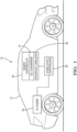
- Fig. 1 illustrates an electrical power supply device, e.g., a Universal Serial Bus (USB) power delivery (PD) device, hereinafter referred to as the PD device 10 that is designed for use in a motor vehicle 12.
- the PD device 10 may be used to support battery charging of USB enabled devices in the vehicle 12 (not shown).
- the PD device 10 includes a buck-only DC-DC power convertor, hereinafter referred to as the DC convertor 14, that receives an input voltage from a vehicle's electrical system.
- the output voltage can by one of at least two different voltages, e.g., a 9 volt output to support a fast USB charge rate or a 5 volt output to support a normal USB charge rate.
- the DC convertor 14, being a buck-only DC-DC power convertor is incapable of providing an output voltage that is greater than the input voltage.
- the PD device 10 also includes a device controller 16 that is in communication with the DC convertor 14.
- the device controller 16 has one or more processors and memory.
- the processors may be a microprocessors, application specific integrated circuits (ASIC), or built from discrete logic and timing circuits (not shown).
- Software instructions that program the processors may be stored in a non-volatile (NV) memory device (not shown).
- the NV memory device may be contained within the microprocessor or ASIC or it may be a separate device.
- Non-limiting examples of the types of NV memory that may be used include electrically erasable programmable read only memory (EEPROM), masked read only memory (ROM), and flash memory.
- the memory stores instructions which causes the device controller 16 to command the DC convertor 14 to output the higher output voltage, e.g., 9 volts, when the input voltage is equal to or greater than a threshold voltage and which causes the device controller 16 to command the DC convertor 14 to output the lower output voltage, e.g., 5 volts, when the input voltage is or will be less than the threshold voltage.
- the threshold voltage is greater than or equal to the higher output voltage.
- the PD device 10 also includes interface circuitry 18, such as a controller area network (CAN) transceiver, a local interconnect network (LIN) transceiver, a USB transceiver, and/or an input voltage detection circuit, e.g., an analog/digital convertor circuit, to allow the PD device 10 to establish electrical communication with other devices within the vehicle 12.
- interface circuitry 18 such as a controller area network (CAN) transceiver, a local interconnect network (LIN) transceiver, a USB transceiver, and/or an input voltage detection circuit, e.g., an analog/digital convertor circuit, to allow the PD device 10 to establish electrical communication with other devices within the vehicle 12.
- CAN controller area network
- LIN local interconnect network
- USB transceiver e.g., USB transceiver
- an input voltage detection circuit e.g., an analog/digital convertor circuit
- this circuit is in communication with the vehicle power supply, e.g. vehicle battery (not shown) and the device controller 16 and is configured to determine the input voltage to the PD device 10 from the vehicle battery and transmit that information to the device controller 16.
- the memory includes additional instructions which cause the device controller 16 to command the DC convertor 14 to output the higher output voltage, e.g. 9 volts, when the input voltage detection circuit determines that the input voltage is greater than the threshold voltage, e.g. 9.5 or 10 volts and which cause the device controller 16 to command the DC convertor 14 to output the lower output voltage, e.g. 5 volts, when the input voltage detection circuit determines that the input voltage is less than the threshold voltage.
- the PD device 10 is in communication with a start-stop controller 20 via the CAN transceiver, the LIN transceiver.
- the memory further includes instructions which cause the device controller 16 to command the DC convertor 14 to output the higher output voltage in accordance with the device controller 16 receiving a run signal from the start-stop controller 20.
- the reception of the run signal causes the device controller 16 to command the DC convertor 14 to output the lower output voltage in accordance with the device controller 16 receiving a stop signal from the start-stop controller 20.
- the run signal indicates that the IC engine 22 is running, therefore the input voltage will remain equal to or greater than the threshold voltage.
- the stop signal indicates that the IC engine 22 is not running and that the input voltage may drop to less than the threshold voltage, e.g. during a cranking transient.
- the PD device 10 is disposed within a USB port that is in communication with a USB hub.
- the memory includes instructions which cause the device controller 16 to command the DC convertor 14 to output the higher output voltage in accordance with the device controller 16 receiving a first USB signal from the USB hub indicating that the input voltage will remain equal to or greater than the threshold voltage and which cause the device controller 16 to command the DC convertor 14 to output the lower output voltage in accordance with the device controller 16 receiving a second signal from the USB hub indicating that the input voltage may drop to less than the threshold voltage.
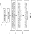
- Fig. 2 illustrates a method 100 of operating the PD device 10 which includes the DC convertor 14 and the device controller 16.
- the method 100 includes the following steps:
- the first and second output voltage are each less than the input voltage.
- the threshold voltage is greater than or equal to the first output voltage.
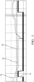
- the PD device 10 has negotiated a PD contract with a consumer device (not shown) at 27 watts i.e., output voltage 24 is 9Vand current capacity is 3A and a start-stop event 26 occurs in the vehicle 12, the PD device 10 will change the power negotiation from 27 watts to 15 watts, i.e., output voltage 24 is 5V and current capacity is 3A. Per the USB PD specifications the consumer device will choose the new 15 watt capability. After the stop-start event ends, the PD device 10 will renegotiate 27 watt capability and the consumer device will choose highest power needed.
- the input voltage 30 is monitored constantly by the PD device 10. If the input voltage 30 drops to the voltage threshold 32, the PD device 10 will negotiate a 15 watt only contract with the consumer device. If the input voltage 30 rises above the voltage threshold 32, PD device 10 will negotiate a 27 watt contract with the consumer device.
- the PD device 10 receives a start-stop signal, e.g., a CAN/LIN/discrete) signal from the vehicle 12 and negotiates a 15 watt contract with the consumer device when the stop-start signal is received, and negotiates a higher power, e.g., 27 watt, contract when the start-stop signal is no longer received or a signal indicating the completion of the start-stop event is received.
- a start-stop signal e.g., a CAN/LIN/discrete
- an electrical power supply device e.g., a USB PD device 10
- a method 100 of operating such a device is provided.
- the device provides the benefit of a USB PD device 10 that is capable of reliable operation in a motor vehicle 12 having a start-stop system at a lower cost than prior USB PD device designs.
- 'one or more' includes a function being performed by one element, a function being performed by more than one element, e.g., in a distributed fashion, several functions being performed by one element, several functions being performed by several elements, or any combination of the above.
- first, second, etc. are, in some instances, used herein to describe various elements, these elements should not be limited by these terms. These terms are only used to distinguish one element from another.
- a first contact could be termed a second contact, and, similarly, a second contact could be termed a first contact, without departing from the scope of the various described embodiments.
- the first contact and the second contact are both contacts, but they are not the same contact.
- the term “if' is, optionally, construed to mean “when” or “upon” or “in response to determining” or “in response to detecting,” depending on the context.
- the phrase “if it is determined” or “if [a stated condition or event] is detected” is, optionally, construed to mean “upon determining” or “in response to determining” or “upon detecting [the stated condition or event]” or “in response to detecting [the stated condition or event],” depending on the context.
- An electrical power supply device comprising: a DC-DC power convertor (14) receiving an input voltage (30) and producing a first output voltage (24) or a second output voltage (24) that is less than the first output voltage (24), the first and second output voltage (24) each less than the input voltage (30); and a device controller (16) in communication with the DC-DC power convertor (14), said device controller (16) having one or more processors and memory, wherein the memory includes instructions which causes the device controller (16) to command the DC-DC power convertor (14) to output the first output voltage (24) when the input voltage (30) is equal to or greater than a threshold voltage (32) and which causes the device controller (16) to command the DC-DC power convertor (14) to output the second output voltage (24) when the input voltage (30) is less than the threshold voltage (32).
- Example 2 The electrical power supply device (10) according to example 1, wherein the threshold voltage (32) is greater than or equal to the first output voltage (24).
- Example 3 The electrical power supply device (10) according to any of examples 1-2, wherein the DC-DC power convertor (14) is incapable of providing an output voltage (24) that is greater than the input voltage (30).
- Example 4 The electrical power supply device (10) according to example 3, wherein the electrical power supply device (10) further comprises an input voltage (30) detection circuit in communication with the device controller (16) and wherein the memory includes additional instructions which causes the device controller (16) to command the DC-DC power convertor (14) to output the second output voltage (24) when the input voltage (30) detection circuit determines that the input voltage (30) is less than the threshold voltage (32).
- Example 5 The electrical power supply device (10) according to example 3, wherein the electrical power supply device (10) is disposed within an automobile having a start-stop controller (20) in communication with the device controller (16), wherein the memory further includes instructions which cause the device controller (16) to command the DC-DC power convertor (14) to output the first output voltage (24) in accordance with the device controller (16) receiving a run signal from the start-stop controller (20), and wherein the memory additionally includes instructions which cause the device controller (16) to command the DC-DC power convertor (14) to output the second output voltage (24) in accordance with the device controller (16) receiving a stop signal from the start-stop controller (20).
- Example 6 The electrical power supply device (10) according to example 5, wherein the start-stop controller (20) is connected to the device controller (16) by a controller area network (CAN) communication bus.
- CAN controller area network
- Example 7 The electrical power supply device (10) according to example 5, wherein the start-stop controller (20) is connected to the device controller (16) by a local interconnect network (LIN) communication bus.
- LIN local interconnect network
- Example 8 The electrical power supply device (10) according to any of examples 5-7, wherein the run signal indicates that the input voltage (30) will remain equal to or greater than the threshold voltage (32) and the stop signal indicates that the input voltage (30) may drop to less than the threshold voltage (32).
- Example 9 The electrical power supply device (10) according to example 3, wherein the electrical power supply device (10) is disposed within a universal serial bus (USB) port in communication with a USB hub, wherein the memory further includes instructions which cause the device controller (16) to command the DC-DC power convertor (14) to output the first output voltage (24) in accordance with the device controller (16) receiving a first USB signal from the USB hub indicating that the input voltage (30) will remain equal to or greater than the threshold voltage (32), and wherein the memory additionally includes instructions which cause the device controller (16) to command the DC-DC power convertor (14) to output the second output voltage (24) in accordance with the device controller (16) receiving a second signal from the USB hub indicating that the input voltage (30) may drop to less than the threshold voltage (32).
- USB universal serial bus
- Example 10 The electrical power supply device (10) according to any preceding example, wherein the first output voltage (24) is about 9 volts and the second output voltage (24) is about 5 volts.
- Example 11 A method (100), comprising: at a device controller (16) and a DC-DC power convertor (14) in communication with the device controller (16), said device controller (16) having one or more processors and memory: receiving (102) an input voltage (30); receiving (104) a signal indicative of whether the input voltage (30) is equal to, greater than, or less than a threshold voltage (32); producing (106) a first output voltage (24) via the DC-DC power convertor (14) in accordance with the device controller (16) determining that the input voltage (30) is equal to the threshold voltage (32); producing (108) the first output voltage (24) via the DC-DC power convertor (14) in accordance with the device controller (16) determining that the input voltage (30) is greater than the threshold voltage (32); and producing (110) a second output voltage (24) via the DC-DC power convertor (14) which is less than the first output voltage (24) in accordance with the device controller (16) determining that the input voltage (30) is less than the threshold voltage (32), wherein the first and second output voltage (24) are each less than the input voltage
- Example 12 The method (100) according to example 11, wherein the threshold voltage (32) is greater than or equal to the first output voltage (24).
- Example 13 The method (100) according to any of examples 11-12, wherein the DC-DC power convertor (14) is incapable of providing an output voltage (24) that is greater than the input voltage (30).
- Example 14 The method (100) according to any of examples 11-13, wherein the first output voltage (24) is about 9 volts and the second output voltage (24) is about 5 volts.
Landscapes
- Engineering & Computer Science (AREA)
- Power Engineering (AREA)
- Mechanical Engineering (AREA)
- General Engineering & Computer Science (AREA)
- Theoretical Computer Science (AREA)
- Physics & Mathematics (AREA)
- General Physics & Mathematics (AREA)
- Automation & Control Theory (AREA)
- Computer Hardware Design (AREA)
- Computer Networks & Wireless Communication (AREA)
- Signal Processing (AREA)
- Charge And Discharge Circuits For Batteries Or The Like (AREA)
- Electric Propulsion And Braking For Vehicles (AREA)
- Dc-Dc Converters (AREA)
- Direct Current Feeding And Distribution (AREA)
Abstract
Description
- The invention generally relates to an electrical power supply device and method of operating the electrical power supply device.
- The problem underlying the present application is solved by an electrical power supply device having the features of claim 1, as well as by a method having the features of claim 9. Preferred embodiments are the subject matter of the dependent claims.
- The present invention will now be described, by way of example with reference to the accompanying drawings, in which:
-
Fig. 1 is a schematic diagram of an electrical power supply device, according to one embodiment; -
Fig. 2 is a flow chart of a method of operating the electrical power supply device, according to one embodiment; and -
Fig. 3 is a graph of an input voltage and an output voltage of the electrical power supply device, according to one embodiment. - Reference will now be made in detail to embodiments, examples of which are illustrated in the accompanying drawings. In the following detailed description, numerous specific details are set forth in order to provide a thorough understanding of the various described embodiments. However, it will be apparent to one of ordinary skill in the art that the various described embodiments may be practiced without these specific details. In other instances, well-known methods, procedures, components, circuits, and networks have not been described in detail so as not to unnecessarily obscure aspects of the embodiments.
- The Universal Serial Bus (USB) has evolved from a data interface capable of supplying limited power to a primary provider of power with a data interface. Today many devices charge or get their power from USB ports contained in laptops, cars, aircraft or even wall sockets. USB has become a ubiquitous power socket for many consumer devices such as cellular telephones, digital media players and/or other hand-held devices. Users utilize USB to fulfil their requirements not only in terms of data but also to provide power to, or charge, their devices simply, often without the need to load a driver, in order to carry out "traditional" USB functions.
- The USB Power Delivery (PD) Specification enables the maximum functionality of USB by providing more flexible power delivery, e.g., for battery charging, along with data over a single cable. Its aim is to operate with and build on the existing USB ecosystem. The USB Power Delivery Specification 3.0 is published by the USB Implementer's Forum, Inc and is incorporated by reference herein.
- Prior implementations of USB PD devices conforming to the USB Power Delivery Specification in automotive applications have used a "buck/boost" DC-DC power converter to generate voltages from 5 volts to 20 volts which are both above and below the typical vehicle input voltage of 12 to 14 volts. Buck/boost DC-DC converters capable of supplying a DC output voltage that is greater or less than the input voltage are more expensive, physically larger, and are less energy efficient than a buck only DC-DC converter which can only supply a DC output voltage that is less than the input voltage. The inventors propose a high efficiency, low cost, entry level USB PD device herein using a buck only DC-DC converter design.
- In order to meet stringent fuel economy and emission standards, automotive original equipment manufacturers (OEMs) have included start-stop technology in their vehicles that automatically shuts down and restarts the internal combustion engine to reduce the amount of time the engine spends idling, thereby reducing fuel consumption and emissions of the vehicle.
- OEMs have imposed requirements for a USB PD device and other automotive electrical modules powered by the vehicle battery requires it to meet "Start/Stop" transient tests in which the vehicle battery voltage temporarily dips down to as low as 6 volts to simulate the vehicle cranking during a warm start. During this transient, the USB PD device is expected to continue to function with no disruption to the consumer experience. With only a 6 volt input voltage during the transient, it is not possible for a buck only DC-DC converter to maintain an output voltage higher than the input voltage, e.g., 9 volts, to the consumer device while being charged.
- A proposed innovative solution is to provide a signal from the vehicle to the USB PD device to indicate the power state of the vehicle. During the normal vehicle run mode the vehicle voltage is expected to be typically in the 12-14V range and a buck only DC-DC converter can generate a 9 volt output used by the consumer charging device in a fast charge mode. When the vehicle enters the stop/start mode, i.e., the vehicle has stopped moving and automatically turns off the engine, the change in mode is communicated by a signal from the vehicle to a controller in the USB PD device and the USB PD device then renegotiates the charging contact with the consumer device to provide a 5 volt output voltage for normal charging operation. When the car subsequently experiences a crank cycle transient, the buck converter is able to maintain the 5 volt output without interrupting the charging session. After the engine starts and returns to the run mode, the USB PD device is again notified via another signal and returns to a 9 volt output. This innovation provides offer a lower cost "entry level" PD solution to customers that are not interested in a full featured and higher cost USB PD device.
-
Fig. 1 illustrates an electrical power supply device, e.g., a Universal Serial Bus (USB) power delivery (PD) device, hereinafter referred to as thePD device 10 that is designed for use in amotor vehicle 12. ThePD device 10 may be used to support battery charging of USB enabled devices in the vehicle 12 (not shown). ThePD device 10 includes a buck-only DC-DC power convertor, hereinafter referred to as theDC convertor 14, that receives an input voltage from a vehicle's electrical system. The output voltage can by one of at least two different voltages, e.g., a 9 volt output to support a fast USB charge rate or a 5 volt output to support a normal USB charge rate. TheDC convertor 14, being a buck-only DC-DC power convertor, is incapable of providing an output voltage that is greater than the input voltage. - The
PD device 10 also includes adevice controller 16 that is in communication with theDC convertor 14. Thedevice controller 16 has one or more processors and memory. The processors may be a microprocessors, application specific integrated circuits (ASIC), or built from discrete logic and timing circuits (not shown). Software instructions that program the processors may be stored in a non-volatile (NV) memory device (not shown). The NV memory device may be contained within the microprocessor or ASIC or it may be a separate device. Non-limiting examples of the types of NV memory that may be used include electrically erasable programmable read only memory (EEPROM), masked read only memory (ROM), and flash memory. The memory stores instructions which causes thedevice controller 16 to command theDC convertor 14 to output the higher output voltage, e.g., 9 volts, when the input voltage is equal to or greater than a threshold voltage and which causes thedevice controller 16 to command theDC convertor 14 to output the lower output voltage, e.g., 5 volts, when the input voltage is or will be less than the threshold voltage. The threshold voltage is greater than or equal to the higher output voltage. - The
PD device 10 also includesinterface circuitry 18, such as a controller area network (CAN) transceiver, a local interconnect network (LIN) transceiver, a USB transceiver, and/or an input voltage detection circuit, e.g., an analog/digital convertor circuit, to allow thePD device 10 to establish electrical communication with other devices within thevehicle 12. - In an embodiment that includes the input voltage detection circuit, this circuit is in communication with the vehicle power supply, e.g. vehicle battery (not shown) and the
device controller 16 and is configured to determine the input voltage to thePD device 10 from the vehicle battery and transmit that information to thedevice controller 16. The memory includes additional instructions which cause thedevice controller 16 to command theDC convertor 14 to output the higher output voltage, e.g. 9 volts, when the input voltage detection circuit determines that the input voltage is greater than the threshold voltage, e.g. 9.5 or 10 volts and which cause thedevice controller 16 to command theDC convertor 14 to output the lower output voltage, e.g. 5 volts, when the input voltage detection circuit determines that the input voltage is less than the threshold voltage. - In another embodiment, the
PD device 10 is in communication with a start-stop controller 20 via the CAN transceiver, the LIN transceiver. The memory further includes instructions which cause thedevice controller 16 to command theDC convertor 14 to output the higher output voltage in accordance with thedevice controller 16 receiving a run signal from the start-stop controller 20. The reception of the run signal causes thedevice controller 16 to command theDC convertor 14 to output the lower output voltage in accordance with thedevice controller 16 receiving a stop signal from the start-stop controller 20. The run signal indicates that theIC engine 22 is running, therefore the input voltage will remain equal to or greater than the threshold voltage. The stop signal indicates that theIC engine 22 is not running and that the input voltage may drop to less than the threshold voltage, e.g. during a cranking transient. - In yet another embodiment, the
PD device 10 is disposed within a USB port that is in communication with a USB hub. The memory includes instructions which cause thedevice controller 16 to command theDC convertor 14 to output the higher output voltage in accordance with thedevice controller 16 receiving a first USB signal from the USB hub indicating that the input voltage will remain equal to or greater than the threshold voltage and which cause thedevice controller 16 to command theDC convertor 14 to output the lower output voltage in accordance with thedevice controller 16 receiving a second signal from the USB hub indicating that the input voltage may drop to less than the threshold voltage. -
Fig. 2 illustrates amethod 100 of operating thePD device 10 which includes theDC convertor 14 and thedevice controller 16. Themethod 100 includes the following steps: -
STEP 102, RECEIVE AN INPUT VOLTAGE, includes thePD device 10 receiving an input voltage from an electrical power source, e.g., a vehicle electrical system; -
STEP 104, RECEIVE A SIGNAL, includes thePD device 10 receiving a signal indicative of whether the input voltage is equal to, greater than, or less than a threshold voltage; -
STEP 106, PRODUCE A FIRST OUTPUT VOLTAGE VIA THE DC CONVERTOR IN ACCORDANCE WITH THE DEVICE CONTROLLER DETERMINING THAT THE INPUT VOLTAGE IS EQUAL TO THE THRESHOLD VOLTAGE, includes thePD device 10 producing a higher output voltage, e.g., 9 volts, via theDC convertor 14 in accordance with thedevice controller 16 determining that the input voltage is equal to the threshold voltage; -
STEP 108, PRODUCE THE FIRST OUTPUT VOLTAGE VIA THE DC-DC POWER CONVERTOR IN ACCORDANCE WITH THE DEVICE CONTROLLER DETERMINING THAT THE INPUT VOLTAGE IS GREATER THAN THE THRESHOLD VOLTAGE, includes thePD device 10 producing the higher output voltage via theDC convertor 14 in accordance with thedevice controller 16 determining that the input voltage is greater than the threshold voltage; and -
STEP 110, PRODUCE A SECOND OUTPUT VOLTAGE VIA THE DC-DC POWER CONVERTOR IN ACCORDANCE WITH THE DEVICE CONTROLLER DETERMINING THAT THE INPUT VOLTAGE IS LESS THAN THE THRESHOLD VOLTAGE, includes thePD device 10 producing a second output voltage via theDC convertor 14 which is less than the first output voltage in accordance with thedevice controller 16 determining that the input voltage is less than the threshold voltage. - The first and second output voltage are each less than the input voltage. The threshold voltage is greater than or equal to the first output voltage.
- According to a particular embodiment, as illustrated in
Fig. 3 if thePD device 10 has negotiated a PD contract with a consumer device (not shown) at 27 watts i.e.,output voltage 24 is 9Vand current capacity is 3A and a start-stop event 26 occurs in thevehicle 12, thePD device 10 will change the power negotiation from 27 watts to 15 watts, i.e.,output voltage 24 is 5V and current capacity is 3A. Per the USB PD specifications the consumer device will choose the new 15 watt capability. After the stop-start event ends, thePD device 10 will renegotiate 27 watt capability and the consumer device will choose highest power needed. - In this embodiment, the
input voltage 30 is monitored constantly by thePD device 10. If theinput voltage 30 drops to thevoltage threshold 32, thePD device 10 will negotiate a 15 watt only contract with the consumer device. If theinput voltage 30 rises above thevoltage threshold 32,PD device 10 will negotiate a 27 watt contract with the consumer device. - Inn an alternative embodiment the
PD device 10 receives a start-stop signal, e.g., a CAN/LIN/discrete) signal from thevehicle 12 and negotiates a 15 watt contract with the consumer device when the stop-start signal is received, and negotiates a higher power, e.g., 27 watt, contract when the start-stop signal is no longer received or a signal indicating the completion of the start-stop event is received. - Accordingly, an electrical power supply device, e.g., a
USB PD device 10, and amethod 100 of operating such a device is provided. The device provides the benefit of aUSB PD device 10 that is capable of reliable operation in amotor vehicle 12 having a start-stop system at a lower cost than prior USB PD device designs. - While this invention has been described in terms of the preferred embodiments thereof, it is not intended to be so limited, but rather only to the extent set forth in the claims that follow. For example, the above-described embodiments (and/or aspects thereof) may be used in combination with each other. In addition, many modifications may be made to configure a particular situation or material to the teachings of the invention without departing from its scope. Dimensions, types of materials, orientations of the various components, and the number and positions of the various components described herein are intended to define parameters of certain embodiments; and are by no means limiting and are merely prototypical embodiments.
- Many other embodiments and modifications within the spirit and scope of the claims will be apparent to those of skill in the art upon reviewing the above description. The scope of the invention should, therefore, be determined with reference to the following claims, along with the full scope of equivalents to which such claims are entitled.
- As used herein, 'one or more' includes a function being performed by one element, a function being performed by more than one element, e.g., in a distributed fashion, several functions being performed by one element, several functions being performed by several elements, or any combination of the above.
- It will also be understood that, although the terms first, second, etc. are, in some instances, used herein to describe various elements, these elements should not be limited by these terms. These terms are only used to distinguish one element from another. For example, a first contact could be termed a second contact, and, similarly, a second contact could be termed a first contact, without departing from the scope of the various described embodiments. The first contact and the second contact are both contacts, but they are not the same contact.
- The terminology used in the description of the various described embodiments herein is for the purpose of describing particular embodiments only and is not intended to be limiting. As used in the description of the various described embodiments and the appended claims, the singular forms "a", "an" and "the" are intended to include the plural forms as well, unless the context clearly indicates otherwise. It will also be understood that the term "and/or" as used herein refers to and encompasses any and all possible combinations of one or more of the associated listed items. It will be further understood that the terms "includes," "including," "comprises," and/or "comprising," when used in this specification, specify the presence of stated features, integers, steps, operations, elements, and/or components, but do not preclude the presence or addition of one or more other features, integers, steps, operations, elements, components, and/or groups thereof.
- As used herein, the term "if' is, optionally, construed to mean "when" or "upon" or "in response to determining" or "in response to detecting," depending on the context. Similarly, the phrase "if it is determined" or "if [a stated condition or event] is detected" is, optionally, construed to mean "upon determining" or "in response to determining" or "upon detecting [the stated condition or event]" or "in response to detecting [the stated condition or event]," depending on the context.
- Additionally, while terms of ordinance or orientation may be used herein these elements should not be limited by these terms. All terms of ordinance or orientation, unless stated otherwise, are used for purposes distinguishing one element from another, and do not denote any particular order, order of operations, direction or orientation unless stated otherwise.
- Although the present disclosure is not so limited, the following numbered examples demonstrate one or more aspects of the disclosure.
- Example 1. An electrical power supply device (10) comprising: a DC-DC power convertor (14) receiving an input voltage (30) and producing a first output voltage (24) or a second output voltage (24) that is less than the first output voltage (24), the first and second output voltage (24) each less than the input voltage (30); and a device controller (16) in communication with the DC-DC power convertor (14), said device controller (16) having one or more processors and memory, wherein the memory includes instructions which causes the device controller (16) to command the DC-DC power convertor (14) to output the first output voltage (24) when the input voltage (30) is equal to or greater than a threshold voltage (32) and which causes the device controller (16) to command the DC-DC power convertor (14) to output the second output voltage (24) when the input voltage (30) is less than the threshold voltage (32).
- Example 2. The electrical power supply device (10) according to example 1, wherein the threshold voltage (32) is greater than or equal to the first output voltage (24).
- Example 3. The electrical power supply device (10) according to any of examples 1-2, wherein the DC-DC power convertor (14) is incapable of providing an output voltage (24) that is greater than the input voltage (30).
- Example 4. The electrical power supply device (10) according to example 3, wherein the electrical power supply device (10) further comprises an input voltage (30) detection circuit in communication with the device controller (16) and wherein the memory includes additional instructions which causes the device controller (16) to command the DC-DC power convertor (14) to output the second output voltage (24) when the input voltage (30) detection circuit determines that the input voltage (30) is less than the threshold voltage (32).
- Example 5 . The electrical power supply device (10) according to example 3, wherein the electrical power supply device (10) is disposed within an automobile having a start-stop controller (20) in communication with the device controller (16), wherein the memory further includes instructions which cause the device controller (16) to command the DC-DC power convertor (14) to output the first output voltage (24) in accordance with the device controller (16) receiving a run signal from the start-stop controller (20), and wherein the memory additionally includes instructions which cause the device controller (16) to command the DC-DC power convertor (14) to output the second output voltage (24) in accordance with the device controller (16) receiving a stop signal from the start-stop controller (20).
- Example 6. The electrical power supply device (10) according to example 5, wherein the start-stop controller (20) is connected to the device controller (16) by a controller area network (CAN) communication bus.
- Example 7. The electrical power supply device (10) according to example 5, wherein the start-stop controller (20) is connected to the device controller (16) by a local interconnect network (LIN) communication bus.
- Example 8. The electrical power supply device (10) according to any of examples 5-7, wherein the run signal indicates that the input voltage (30) will remain equal to or greater than the threshold voltage (32) and the stop signal indicates that the input voltage (30) may drop to less than the threshold voltage (32).
- Example 9. The electrical power supply device (10) according to example 3, wherein the electrical power supply device (10) is disposed within a universal serial bus (USB) port in communication with a USB hub, wherein the memory further includes instructions which cause the device controller (16) to command the DC-DC power convertor (14) to output the first output voltage (24) in accordance with the device controller (16) receiving a first USB signal from the USB hub indicating that the input voltage (30) will remain equal to or greater than the threshold voltage (32), and wherein the memory additionally includes instructions which cause the device controller (16) to command the DC-DC power convertor (14) to output the second output voltage (24) in accordance with the device controller (16) receiving a second signal from the USB hub indicating that the input voltage (30) may drop to less than the threshold voltage (32).
- Example 10. The electrical power supply device (10) according to any preceding example, wherein the first output voltage (24) is about 9 volts and the second output voltage (24) is about 5 volts.
- Example 11. A method (100), comprising: at a device controller (16) and a DC-DC power convertor (14) in communication with the device controller (16), said device controller (16) having one or more processors and memory: receiving (102) an input voltage (30); receiving (104) a signal indicative of whether the input voltage (30) is equal to, greater than, or less than a threshold voltage (32); producing (106) a first output voltage (24) via the DC-DC power convertor (14) in accordance with the device controller (16) determining that the input voltage (30) is equal to the threshold voltage (32); producing (108) the first output voltage (24) via the DC-DC power convertor (14) in accordance with the device controller (16) determining that the input voltage (30) is greater than the threshold voltage (32); and producing (110) a second output voltage (24) via the DC-DC power convertor (14) which is less than the first output voltage (24) in accordance with the device controller (16) determining that the input voltage (30) is less than the threshold voltage (32), wherein the first and second output voltage (24) are each less than the input voltage (30).
- Example 12. The method (100) according to example 11, wherein the threshold voltage (32) is greater than or equal to the first output voltage (24).
- Example 13. The method (100) according to any of examples 11-12, wherein the DC-DC power convertor (14) is incapable of providing an output voltage (24) that is greater than the input voltage (30).
- Example 14. The method (100) according to any of examples 11-13, wherein the first output voltage (24) is about 9 volts and the second output voltage (24) is about 5 volts.
Claims (12)
- An electrical power supply device (10), comprising:a DC-DC power convertor (14) receiving an input voltage (30) and producing a first output voltage (24) or a second output voltage (24) that is less than the first output voltage (24), the first and second output voltage (24) each less than the input voltage (30); anda device controller (16) in communication with the DC-DC power convertor (14), said device controller (16) having one or more processors and memory, wherein the memory includes instructions which causes the device controller (16) to command the DC-DC power convertor (14) to output the first output voltage (24) when the input voltage (30) is equal to or greater than a threshold voltage (32) and which causes the device controller (16) to command the DC-DC power convertor (14) to output the second output voltage (24) when the input voltage (30) is less than the threshold voltage (32), wherein the DC-DC power convertor (14) is incapable of providing an output voltage (24) that is greater than the input voltage (30), wherein the electrical power supply device (10) is disposed within an automobile having a start-stop controller (20) in communication with the device controller (16), wherein the memory further includes instructions which cause the device controller (16) to command the DC-DC power convertor (14) to output the first output voltage (24) in accordance with the device controller (16) receiving a run signal from the start-stop controller (20), and wherein the memory additionally includes instructions which cause the device controller (16) to command the DC-DC power convertor (14) to output the second output voltage (24) in accordance with the device controller (16) receiving a stop signal from the start-stop controller (20).
- The electrical power supply device (10) according to claim 1, wherein the start-stop controller (20) is connected to the device controller (16) by a controller area network (CAN) communication bus.
- The electrical power supply device (10) according to any preceding claim, wherein the start-stop controller (20) is connected to the device controller (16) by a local interconnect network (LIN) communication bus.
- The electrical power supply device (10) according to any preceding claim, wherein the run signal indicates that the input voltage (30) will remain equal to or greater than the threshold voltage (32) and the stop signal indicates that the input voltage (30) may drop to less than the threshold voltage (32).
- The electrical power supply device (10) according to any preceding claim, wherein the electrical power supply device (10) is disposed within a universal serial bus (USB) port in communication with a USB hub, wherein the memory further includes instructions which cause the device controller (16) to command the DC-DC power convertor (14) to output the first output voltage (24) in accordance with the device controller (16) receiving a first USB signal from the USB hub indicating that the input voltage (30) will remain equal to or greater than the threshold voltage (32), and wherein the memory additionally includes instructions which cause the device controller (16) to command the DC-DC power convertor (14) to output the second output voltage (24) in accordance with the device controller (16) receiving a second signal from the USB hub indicating that the input voltage (30) may drop to less than the threshold voltage (32).
- The electrical power supply device (10) according to any preceding claim, wherein the first output voltage (24) is about 9 volts, and the second output voltage (24) is about 5 volts.
- The electrical power supply device (10) according to any preceding claim, wherein the threshold voltage (32) is greater than or equal to the first output voltage (24).
- The electrical power supply device (10) according to any preceding claim, wherein the electrical power supply device (10) further comprises an input voltage (30) detection circuit in communication with the device controller (16) and wherein the memory includes additional instructions which causes the device controller (16) to command the DC-DC power convertor (14) to output the second output voltage (24) when the input voltage (30) detection circuit determines that the input voltage (30) is less than the threshold voltage (32).
- A method (100), comprising:providing a device controller (16) and a DC-DC power convertor (14) in communication with the device controller (16), said device controller (16) having one or more processors and memory;receiving (102) an input voltage (30);receiving (104) a signal indicative of whether the input voltage (30) is equal to, greater than, or less than a threshold voltage (32);producing (106) a first output voltage (24) via the DC-DC power convertor (14) in accordance with the device controller (16) determining that the input voltage (30) is equal to the threshold voltage (32);producing (108) the first output voltage (24) via the DC-DC power convertor (14) in accordance with the device controller (16) determining that the input voltage (30) is greater than the threshold voltage (32); andproducing (110) a second output voltage (24) via the DC-DC power convertor (14) which is less than the first output voltage (24) in accordance with the device controller (16) determining that the input voltage (30) is less than the threshold voltage (32), wherein the first and second output voltage (24) are each less than the input voltage (30).
- The method (100) according to claim 9, wherein the threshold voltage (32) is greater than or equal to the first output voltage (24).
- The method (100) according to any of claims 9-10, wherein the DC-DC power convertor (14) is incapable of providing an output voltage (24) that is greater than the input voltage (30).
- The method (100) according to any of claims 9-11, wherein the first output voltage (24) is about 9 volts, and the second output voltage (24) is about 5 volts.
Applications Claiming Priority (2)
| Application Number | Priority Date | Filing Date | Title |
|---|---|---|---|
| US15/954,851 US10635150B2 (en) | 2018-04-17 | 2018-04-17 | Electrical power supply device and method of operating same |
| EP19164904.5A EP3557723B1 (en) | 2018-04-17 | 2019-03-25 | Electrical power supply device and method of operating same |
Related Parent Applications (2)
| Application Number | Title | Priority Date | Filing Date |
|---|---|---|---|
| EP19164904.5A Division-Into EP3557723B1 (en) | 2018-04-17 | 2019-03-25 | Electrical power supply device and method of operating same |
| EP19164904.5A Division EP3557723B1 (en) | 2018-04-17 | 2019-03-25 | Electrical power supply device and method of operating same |
Publications (2)
| Publication Number | Publication Date |
|---|---|
| EP4368458A2 true EP4368458A2 (en) | 2024-05-15 |
| EP4368458A3 EP4368458A3 (en) | 2024-07-31 |
Family
ID=65911087
Family Applications (2)
| Application Number | Title | Priority Date | Filing Date |
|---|---|---|---|
| EP19164904.5A Active EP3557723B1 (en) | 2018-04-17 | 2019-03-25 | Electrical power supply device and method of operating same |
| EP24166900.1A Pending EP4368458A3 (en) | 2018-04-17 | 2019-03-25 | Electrical power supply device and method of operating same |
Family Applications Before (1)
| Application Number | Title | Priority Date | Filing Date |
|---|---|---|---|
| EP19164904.5A Active EP3557723B1 (en) | 2018-04-17 | 2019-03-25 | Electrical power supply device and method of operating same |
Country Status (5)
| Country | Link |
|---|---|
| US (1) | US10635150B2 (en) |
| EP (2) | EP3557723B1 (en) |
| JP (1) | JP6727369B2 (en) |
| KR (1) | KR102209317B1 (en) |
| CN (1) | CN110391740B (en) |
Families Citing this family (5)
| Publication number | Priority date | Publication date | Assignee | Title |
|---|---|---|---|---|
| US11342705B2 (en) * | 2018-04-17 | 2022-05-24 | Aptiv Technologies Limited | Electrical power supply device and method of operating same |
| US11652315B2 (en) * | 2018-04-17 | 2023-05-16 | Aptiv Technologies Limited | Electrical power supply device |
| US11119548B2 (en) * | 2020-01-08 | 2021-09-14 | Cypress Semiconductor Corporation | Dynamic power throttling based on system conditions in USB Type-C power delivery (USB-C/PD) ecosystem |
| CN116800140A (en) * | 2022-03-18 | 2023-09-22 | 台达电子工业股份有限公司 | DC motor drive system and method |
| CN118232697A (en) | 2022-12-21 | 2024-06-21 | 安波福电气系统有限公司 | Isolated bidirectional DC conversion circuit and control method thereof |
Family Cites Families (17)
| Publication number | Priority date | Publication date | Assignee | Title |
|---|---|---|---|---|
| JP3892528B2 (en) | 1997-05-19 | 2007-03-14 | 日産自動車株式会社 | Auxiliary power supply battery charge control device for hybrid electric vehicle |
| JP3637876B2 (en) * | 2001-04-05 | 2005-04-13 | トヨタ自動車株式会社 | Control device for DC-DC converter |
| DE102004023620B4 (en) | 2004-05-10 | 2018-01-04 | Volkswagen Ag | Method and device for energy management in a motor vehicle |
| JP5234139B2 (en) * | 2010-05-20 | 2013-07-10 | 株式会社日本自動車部品総合研究所 | Wireless communication device |
| KR101987992B1 (en) * | 2012-10-24 | 2019-06-11 | 현대모비스 주식회사 | Device of video recording for vehicle using impact detection function and method thereof |
| KR101494412B1 (en) * | 2013-02-08 | 2015-02-23 | 주식회사 피엘케이 테크놀로지 | Complex remote engine start system through multi-chnnel |
| TWI507873B (en) * | 2013-07-29 | 2015-11-11 | Hon Hai Prec Ind Co Ltd | Power adapter and electronic device |
| CN105518969A (en) * | 2013-09-09 | 2016-04-20 | 苹果公司 | Battery charger with buck-boost operation |
| US9444281B2 (en) * | 2014-01-03 | 2016-09-13 | Apple Inc. | Unified high power and low power battery charger |
| US9590503B2 (en) * | 2014-09-17 | 2017-03-07 | Monolithic Power Systems, Inc. | Switching converter and associated discharge method |
| EP3043442B1 (en) | 2015-01-12 | 2024-12-04 | SIMPower Technology Inc. | Hub having complex power converters |
| US9473028B1 (en) * | 2015-04-29 | 2016-10-18 | Hamilton Sundstrand Corporation | Systems and methods for controlling power converters |
| JP6446325B2 (en) * | 2015-05-08 | 2018-12-26 | オムロンオートモーティブエレクトロニクス株式会社 | Power supply device |
| US10044209B2 (en) * | 2015-12-01 | 2018-08-07 | GM Global Technology Operations LLC | Method and apparatus for charging a high-voltage battery assembly |
| JP6777849B2 (en) * | 2016-07-13 | 2020-10-28 | ミツミ電機株式会社 | Charging control circuit for in-vehicle charging connector, in-vehicle charging connector, and in-vehicle data transfer / charging system to external devices |
| JP6719332B2 (en) * | 2016-08-24 | 2020-07-08 | Fdk株式会社 | Charger |
| CN107786088B (en) * | 2016-08-29 | 2021-07-09 | 中兴通讯股份有限公司 | Power supply circuit, power supply circuit control method, and storage medium |
-
2018
- 2018-04-17 US US15/954,851 patent/US10635150B2/en active Active
-
2019
- 2019-03-25 EP EP19164904.5A patent/EP3557723B1/en active Active
- 2019-03-25 EP EP24166900.1A patent/EP4368458A3/en active Pending
- 2019-04-10 KR KR1020190041913A patent/KR102209317B1/en active Active
- 2019-04-15 JP JP2019076870A patent/JP6727369B2/en active Active
- 2019-04-16 CN CN201910302561.XA patent/CN110391740B/en active Active
Also Published As
| Publication number | Publication date |
|---|---|
| CN110391740A (en) | 2019-10-29 |
| KR20190121248A (en) | 2019-10-25 |
| US20190317581A1 (en) | 2019-10-17 |
| JP2019198217A (en) | 2019-11-14 |
| EP3557723B1 (en) | 2024-06-05 |
| CN110391740B (en) | 2021-04-27 |
| JP6727369B2 (en) | 2020-07-22 |
| KR102209317B1 (en) | 2021-02-01 |
| EP3557723A1 (en) | 2019-10-23 |
| US10635150B2 (en) | 2020-04-28 |
| EP4368458A3 (en) | 2024-07-31 |
Similar Documents
| Publication | Publication Date | Title |
|---|---|---|
| EP3557723A1 (en) | Electrical power supply device and method of operating same | |
| EP3557724B1 (en) | Electrical power supply device and method of operating same | |
| CN107985229B (en) | Battery management system and control method thereof | |
| US9296305B2 (en) | Charging apparatus for vehicles | |
| CN106183860B (en) | Vehicle charging method, device, and vehicle controller remote control strategy | |
| CN102540082B (en) | Determine starter battery method and apparatus of starting capability under start-stop operation pattern | |
| WO2013067292A2 (en) | A dual energy storage system for micro hybrid vehicles | |
| JP7458326B2 (en) | Battery monitoring control circuit | |
| WO2013054435A1 (en) | Electric vehicle charging device | |
| WO2005123442A2 (en) | System and method for electrical energy switching and control | |
| US11342705B2 (en) | Electrical power supply device and method of operating same | |
| US11652315B2 (en) | Electrical power supply device | |
| CN110832729A (en) | Power Control Unit and Battery Unit | |
| US10185380B1 (en) | Electrical power supply device and method of operating same | |
| CN107813779B (en) | power supply unit for vehicle | |
| CN117277458B (en) | An automatic power supply control circuit and method based on a vehicle-mounted 24V system | |
| US20150210177A1 (en) | Controlling device for electric vehicle charger | |
| CN116160857A (en) | On-vehicle power supply system and its self-checking method and vehicle | |
| CN120999806A (en) | Reverse charging systems, methods, and vehicles for vehicles | |
| CN114362336A (en) | Energy recovery and utilization control device and control method | |
| KR20140055184A (en) | Apparatus and method for early starting of vehicle |
Legal Events
| Date | Code | Title | Description |
|---|---|---|---|
| PUAI | Public reference made under article 153(3) epc to a published international application that has entered the european phase |
Free format text: ORIGINAL CODE: 0009012 |
|
| STAA | Information on the status of an ep patent application or granted ep patent |
Free format text: STATUS: THE APPLICATION HAS BEEN PUBLISHED |
|
| AC | Divisional application: reference to earlier application |
Ref document number: 3557723 Country of ref document: EP Kind code of ref document: P |
|
| AK | Designated contracting states |
Kind code of ref document: A2 Designated state(s): AL AT BE BG CH CY CZ DE DK EE ES FI FR GB GR HR HU IE IS IT LI LT LU LV MC MK MT NL NO PL PT RO RS SE SI SK SM TR |
|
| RAP1 | Party data changed (applicant data changed or rights of an application transferred) |
Owner name: APTIV TECHNOLOGIES AG |
|
| REG | Reference to a national code |
Ref country code: DE Ref legal event code: R079 Free format text: PREVIOUS MAIN CLASS: B60R0016030000 Ipc: H02J0007140000 |
|
| PUAL | Search report despatched |
Free format text: ORIGINAL CODE: 0009013 |
|
| AK | Designated contracting states |
Kind code of ref document: A3 Designated state(s): AL AT BE BG CH CY CZ DE DK EE ES FI FR GB GR HR HU IE IS IT LI LT LU LV MC MK MT NL NO PL PT RO RS SE SI SK SM TR |
|
| RIC1 | Information provided on ipc code assigned before grant |
Ipc: H02J 7/00 20060101ALN20240625BHEP Ipc: B60R 16/03 20060101ALI20240625BHEP Ipc: H02J 7/14 20060101AFI20240625BHEP |
|
| RAP3 | Party data changed (applicant data changed or rights of an application transferred) |
Owner name: APTIV TECHNOLOGIES AG |
|
| STAA | Information on the status of an ep patent application or granted ep patent |
Free format text: STATUS: REQUEST FOR EXAMINATION WAS MADE |
|
| 17P | Request for examination filed |
Effective date: 20241202 |
|
| RBV | Designated contracting states (corrected) |
Designated state(s): AL AT BE BG CH CY CZ DE DK EE ES FI FR GB GR HR HU IE IS IT LI LT LU LV MC MK MT NL NO PL PT RO RS SE SI SK SM TR |
|
| STAA | Information on the status of an ep patent application or granted ep patent |
Free format text: STATUS: EXAMINATION IS IN PROGRESS |