EP4367870B1 - Übertragung von zuvor komprimierten paketen zur vermeidung von durchsatzabfall - Google Patents
Übertragung von zuvor komprimierten paketen zur vermeidung von durchsatzabfall Download PDFInfo
- Publication number
- EP4367870B1 EP4367870B1 EP22744586.3A EP22744586A EP4367870B1 EP 4367870 B1 EP4367870 B1 EP 4367870B1 EP 22744586 A EP22744586 A EP 22744586A EP 4367870 B1 EP4367870 B1 EP 4367870B1
- Authority
- EP
- European Patent Office
- Prior art keywords
- data packets
- compression state
- wireless device
- state
- compression
- Prior art date
- Legal status (The legal status is an assumption and is not a legal conclusion. Google has not performed a legal analysis and makes no representation as to the accuracy of the status listed.)
- Active
Links
Images







Classifications
-
- H—ELECTRICITY
- H04—ELECTRIC COMMUNICATION TECHNIQUE
- H04L—TRANSMISSION OF DIGITAL INFORMATION, e.g. TELEGRAPHIC COMMUNICATION
- H04L69/00—Network arrangements, protocols or services independent of the application payload and not provided for in the other groups of this subclass
- H04L69/04—Protocols for data compression, e.g. ROHC
-
- H—ELECTRICITY
- H04—ELECTRIC COMMUNICATION TECHNIQUE
- H04W—WIRELESS COMMUNICATION NETWORKS
- H04W28/00—Network traffic management; Network resource management
- H04W28/02—Traffic management, e.g. flow control or congestion control
- H04W28/06—Optimizing the usage of the radio link, e.g. header compression, information sizing, discarding information
-
- H—ELECTRICITY
- H03—ELECTRONIC CIRCUITRY
- H03M—CODING; DECODING; CODE CONVERSION IN GENERAL
- H03M7/00—Conversion of a code where information is represented by a given sequence or number of digits to a code where the same, similar or subset of information is represented by a different sequence or number of digits
- H03M7/30—Compression; Expansion; Suppression of unnecessary data, e.g. redundancy reduction
- H03M7/60—General implementation details not specific to a particular type of compression
- H03M7/6064—Selection of Compressor
-
- H—ELECTRICITY
- H04—ELECTRIC COMMUNICATION TECHNIQUE
- H04L—TRANSMISSION OF DIGITAL INFORMATION, e.g. TELEGRAPHIC COMMUNICATION
- H04L65/00—Network arrangements, protocols or services for supporting real-time applications in data packet communication
- H04L65/10—Architectures or entities
- H04L65/1016—IP multimedia subsystem [IMS]
-
- H—ELECTRICITY
- H04—ELECTRIC COMMUNICATION TECHNIQUE
- H04L—TRANSMISSION OF DIGITAL INFORMATION, e.g. TELEGRAPHIC COMMUNICATION
- H04L65/00—Network arrangements, protocols or services for supporting real-time applications in data packet communication
- H04L65/1066—Session management
- H04L65/1069—Session establishment or de-establishment
-
- H—ELECTRICITY
- H04—ELECTRIC COMMUNICATION TECHNIQUE
- H04L—TRANSMISSION OF DIGITAL INFORMATION, e.g. TELEGRAPHIC COMMUNICATION
- H04L65/00—Network arrangements, protocols or services for supporting real-time applications in data packet communication
- H04L65/60—Network streaming of media packets
- H04L65/65—Network streaming protocols, e.g. real-time transport protocol [RTP] or real-time control protocol [RTCP]
-
- H—ELECTRICITY
- H04—ELECTRIC COMMUNICATION TECHNIQUE
- H04L—TRANSMISSION OF DIGITAL INFORMATION, e.g. TELEGRAPHIC COMMUNICATION
- H04L65/00—Network arrangements, protocols or services for supporting real-time applications in data packet communication
- H04L65/60—Network streaming of media packets
- H04L65/70—Media network packetisation
-
- H—ELECTRICITY
- H04—ELECTRIC COMMUNICATION TECHNIQUE
- H04L—TRANSMISSION OF DIGITAL INFORMATION, e.g. TELEGRAPHIC COMMUNICATION
- H04L69/00—Network arrangements, protocols or services independent of the application payload and not provided for in the other groups of this subclass
- H04L69/22—Parsing or analysis of headers
-
- H—ELECTRICITY
- H03—ELECTRONIC CIRCUITRY
- H03M—CODING; DECODING; CODE CONVERSION IN GENERAL
- H03M7/00—Conversion of a code where information is represented by a given sequence or number of digits to a code where the same, similar or subset of information is represented by a different sequence or number of digits
- H03M7/30—Compression; Expansion; Suppression of unnecessary data, e.g. redundancy reduction
- H03M7/60—General implementation details not specific to a particular type of compression
- H03M7/6047—Power optimization with respect to the encoder, decoder, storage or transmission
-
- H—ELECTRICITY
- H04—ELECTRIC COMMUNICATION TECHNIQUE
- H04L—TRANSMISSION OF DIGITAL INFORMATION, e.g. TELEGRAPHIC COMMUNICATION
- H04L69/00—Network arrangements, protocols or services independent of the application payload and not provided for in the other groups of this subclass
- H04L69/16—Implementation or adaptation of Internet protocol [IP], of transmission control protocol [TCP] or of user datagram protocol [UDP]
-
- H—ELECTRICITY
- H04—ELECTRIC COMMUNICATION TECHNIQUE
- H04L—TRANSMISSION OF DIGITAL INFORMATION, e.g. TELEGRAPHIC COMMUNICATION
- H04L69/00—Network arrangements, protocols or services independent of the application payload and not provided for in the other groups of this subclass
- H04L69/30—Definitions, standards or architectural aspects of layered protocol stacks
- H04L69/32—Architecture of open systems interconnection [OSI] 7-layer type protocol stacks, e.g. the interfaces between the data link level and the physical level
- H04L69/322—Intralayer communication protocols among peer entities or protocol data unit [PDU] definitions
- H04L69/324—Intralayer communication protocols among peer entities or protocol data unit [PDU] definitions in the data link layer [OSI layer 2], e.g. HDLC
Definitions
- the present disclosure relates generally to communication systems, and more particularly, to data compression in a wireless communication system.
- Wireless communication systems are widely deployed to provide various telecommunication services such as telephony, video, data, messaging, and broadcasts.
- Typical wireless communication systems may employ multiple-access technologies capable of supporting communication with multiple users by sharing available system resources. Examples of such multiple-access technologies include code division multiple access (CDMA) systems, time division multiple access (TDMA) systems, frequency division multiple access (FDMA) systems, orthogonal frequency division multiple access (OFDMA) systems, single-carrier frequency division multiple access (SC-FDMA) systems, and time division synchronous code division multiple access (TD-SCDMA) systems.
- CDMA code division multiple access
- TDMA time division multiple access
- FDMA frequency division multiple access
- OFDMA orthogonal frequency division multiple access
- SC-FDMA single-carrier frequency division multiple access
- TD-SCDMA time division synchronous code division multiple access
- WO 2013/001838 A1 relates to data transmission technology, in particular to a data transmission method and device.
- WO 2021/062728 A1 relates to a receiving apparatus, a transmitting apparatus, and a feedback method in a receiving apparatus for communicating packet data having a compressible header.
- 5G New Radio is part of a continuous mobile broadband evolution promulgated by Third Generation Partnership Project (3GPP) to meet new requirements associated with latency, reliability, security, scalability (e.g., with Internet of Things (IoT)), and other requirements.
- 3GPP Third Generation Partnership Project
- 5G NR includes services associated with enhanced mobile broadband (eMBB), massive machine type communications (mMTC), and ultra-reliable low latency communications (URLLC).
- eMBB enhanced mobile broadband
- mMTC massive machine type communications
- URLLC ultra-reliable low latency communications
- Some aspects of 5G NR may be based on the 4G Long Term Evolution (LTE) standard.
- LTE Long Term Evolution
- Software shall be construed broadly to mean instructions, instruction sets, code, code segments, program code, programs, subprograms, software components, applications, software applications, software packages, routines, subroutines, objects, executables, threads of execution, procedures, functions, etc., whether referred to as software, firmware, middleware, microcode, hardware description language, or otherwise.
- the functions described may be implemented in hardware, software, or any combination thereof. If implemented in software, the functions may be stored on or encoded as one or more instructions or code on a computer-readable medium.
- Computer-readable media includes computer storage media. Storage media may be any available media that can be accessed by a computer.
- such computer-readable media can comprise a random-access memory (RAM), a read-only memory (ROM), an electrically erasable programmable ROM (EEPROM), optical disk storage, magnetic disk storage, other magnetic storage devices, combinations of the aforementioned types of computer-readable media, or any other medium that can be used to store computer executable code in the form of instructions or data structures that can be accessed by a computer.
- implementations and/or uses may come about via integrated chip implementations and other non-module-component based devices (e.g., end-user devices, vehicles, communication devices, computing devices, industrial equipment, retail/purchasing devices, medical devices, artificial intelligence (AI)-enabled devices, etc.). While some examples may or may not be specifically directed to use cases or applications, a wide assortment of applicability of described innovations may occur.
- non-module-component based devices e.g., end-user devices, vehicles, communication devices, computing devices, industrial equipment, retail/purchasing devices, medical devices, artificial intelligence (AI)-enabled devices, etc.
- Implementations may range a spectrum from chip-level or modular components to non-modular, non-chip-level implementations and further to aggregate, distributed, or original equipment manufacturer (OEM) devices or systems incorporating one or more aspects of the described innovations.
- devices incorporating described aspects and features may also include additional components and features for implementation and practice of claimed and described aspect.
- transmission and reception of wireless signals necessarily includes a number of components for analog and digital purposes (e.g., hardware components including antenna, RF-chains, power amplifiers, modulators, buffer, processor(s), interleaver, adders/summers, etc.).
- innovations described herein may be practiced in a wide variety of devices, chip-level components, systems, distributed arrangements, end-user devices, etc. of varying sizes, shapes, and constitution.
- FIG. 1 is a diagram illustrating an example of a wireless communications system and an access network 100.
- the wireless communications system (also referred to as a wireless wide area network (WWAN)) includes base stations 102, UEs 104, an Evolved Packet Core (EPC) 160, and another core network 190 (e.g., a 5G Core (5GC)).
- the base stations 102 may include macrocells (high power cellular base station) and/or small cells (low power cellular base station).
- the macrocells include base stations.
- the small cells include femtocells, picocells, and microcells.
- the base stations 102 configured for 4G LTE may interface with the EPC 160 through first backhaul links 132 (e.g., S1 interface).
- the base stations 102 configured for 5G NR may interface with core network 190 through second backhaul links 184.
- UMTS Universal Mobile Telecommunications System
- 5G NR Next Generation RAN
- the base stations 102 may perform one or more of the following functions: transfer of user data, radio channel ciphering and deciphering, integrity protection, header compression, mobility control functions (e.g., handover, dual connectivity), inter-cell interference coordination, connection setup and release, load balancing, distribution for non-access stratum (NAS) messages, NAS node selection, synchronization, radio access network (RAN) sharing, multimedia broadcast multicast service (MBMS), subscriber and equipment trace, RAN information management (RIM), paging, positioning, and delivery of warning messages.
- the base stations 102 may communicate directly or indirectly (e.g., through the EPC 160 or core network 190) with each other over third backhaul links 134 (e.g., X2 interface).
- the first backhaul links 132, the second backhaul links 184, and the third backhaul links 134 may be wired or wireless.
- the base stations 102 may wirelessly communicate with the UEs 104. Each of the base stations 102 may provide communication coverage for a respective geographic coverage area 110. There may be overlapping geographic coverage areas 110. For example, the small cell 102' may have a coverage area 110' that overlaps the coverage area 110 of one or more macro base stations 102.
- a network that includes both small cell and macrocells may be known as a heterogeneous network.
- a heterogeneous network may also include Home Evolved Node Bs (eNBs) (HeNBs), which may provide service to a restricted group known as a closed subscriber group (CSG).
- eNBs Home Evolved Node Bs
- CSG closed subscriber group
- the communication links 120 between the base stations 102 and the UEs 104 may include uplink (UL) (also referred to as reverse link) transmissions from a UE 104 to a base station 102 and/or downlink (DL) (also referred to as forward link) transmissions from a base station 102 to a UE 104.
- the communication links 120 may use multiple-in put and multiple-output (MIMO) antenna technology, including spatial multiplexing, beamforming, and/or transmit diversity.
- the communication links may be through one or more carriers.
- the base stations 102 / UEs 104 may use spectrum up to Y MHz (e.g., 5, 10, 15, 20, 100, 400, etc.
- the component carriers may include a primary component carrier and one or more secondary component carriers.
- a primary component carrier may be referred to as a primary cell (PCell) and a secondary component carrier may be referred to as a secondary cell (SCell).
- D2D communication link 158 may use the DL/UL WWAN spectrum.
- the D2D communication link 158 may use one or more sidelink channels, such as a physical sidelink broadcast channel (PSBCH), a physical sidelink discovery channel (PSDCH), a physical sidelink shared channel (PSSCH), and a physical sidelink control channel (PSCCH).
- sidelink channels such as a physical sidelink broadcast channel (PSBCH), a physical sidelink discovery channel (PSDCH), a physical sidelink shared channel (PSSCH), and a physical sidelink control channel (PSCCH).
- sidelink channels such as a physical sidelink broadcast channel (PSBCH), a physical sidelink discovery channel (PSDCH), a physical sidelink shared channel (PSSCH), and a physical sidelink control channel (PSCCH).
- sidelink channels such as a physical sidelink broadcast channel (PSBCH), a physical sidelink discovery channel (PSDCH), a physical sidelink shared channel (PSSCH), and a physical sidelink control channel (PSCCH).
- the wireless communications system may further include a Wi-Fi access point (AP) 150 in communication with Wi-Fi stations (STAs) 152 via communication links 154, e.g., in a 5 GHz unlicensed frequency spectrum or the like.
- AP Wi-Fi access point
- STAs Wi-Fi stations
- communication links 154 e.g., in a 5 GHz unlicensed frequency spectrum or the like.
- the STAs 152 / AP 150 may perform a clear channel assessment (CCA) prior to communicating in order to determine whether the channel is available.
- CCA clear channel assessment
- the small cell 102' may operate in a licensed and/or an unlicensed frequency spectrum. When operating in an unlicensed frequency spectrum, the small cell 102' may employ NR and use the same unlicensed frequency spectrum (e.g., 5 GHz, or the like) as used by the Wi-Fi AP 150. The small cell 102', employing NR in an unlicensed frequency spectrum, may boost coverage to and/or increase capacity of the access network.
- the small cell 102' employing NR in an unlicensed frequency spectrum, may boost coverage to and/or increase capacity of the access network.
- FR1 frequency range designations FR1 (410 MHz - 7.125 GHz) and FR2 (24.25 GHz - 52.6 GHz). Although a portion of FR1 is greater than 6 GHz, FR1 is often referred to (interchangeably) as a "sub-6 GHz" band in various documents and articles.
- FR2 which is often referred to (interchangeably) as a "millimeter wave” band in documents and articles, despite being different from the extremely high frequency (EHF) band (30 GHz - 300 GHz) which is identified by the International Telecommunications Union (ITU) as a "millimeter wave” band.
- EHF extremely high frequency
- ITU International Telecommunications Union
- FR3 7.125 GHz - 24.25 GHz
- FR3 7.125 GHz - 24.25 GHz
- Frequency bands falling within FR3 may inherit FR1 characteristics and/or FR2 characteristics, and thus may effectively extend features of FR1 and/or FR2 into mid-band frequencies.
- higher frequency bands are currently being explored to extend 5G NR operation beyond 52.6 GHz.
- FR4a or FR4-1 52.6 GHz - 71 GHz
- FR4 52.6 GHz - 114.25 GHz
- FR5 114.25 GHz - 300 GHz.
- Each of these higher frequency bands falls within the EHF band.
- sub-6 GHz or the like if used herein may broadly represent frequencies that may be less than 6 GHz, may be within FR1, or may include mid-band frequencies.
- millimeter wave or the like if used herein may broadly represent frequencies that may include mid-band frequencies, may be within FR2, FR4, FR4-a or FR4-1, and/or FR5, or may be within the EHF band.
- a base station 102 may include and/or be referred to as an eNB, gNodeB (gNB), or another type of base station.
- Some base stations, such as gNB 180 may operate in a traditional sub 6 GHz spectrum, in millimeter wave frequencies, and/or near millimeter wave frequencies in communication with the UE 104.
- the gNB 180 may be referred to as a millimeter wave base station.
- the millimeter wave base station 180 may utilize beamforming 182 with the UE 104 to compensate for the path loss and short range.
- the base station 180 and the UE 104 may each include a plurality of antennas, such as antenna elements, antenna panels, and/or antenna arrays to facilitate the beamforming.
- the base station 180 may transmit a beamformed signal to the UE 104 in one or more transmit directions 182'.
- the UE 104 may receive the beamformed signal from the base station 180 in one or more receive directions 182".
- the UE 104 may also transmit a beamformed signal to the base station 180 in one or more transmit directions.
- the base station 180 may receive the beamformed signal from the UE 104 in one or more receive directions.
- the base station 180 / UE 104 may perform beam training to determine the best receive and transmit directions for each of the base station 180 / UE 104.
- the transmit and receive directions for the base station 180 may or may not be the same.
- the transmit and receive directions for the UE 104 may or may not be the same.
- the EPC 160 may include a Mobility Management Entity (MME) 162, other MMEs 164, a Serving Gateway 166, a Multimedia Broadcast Multicast Service (MBMS) Gateway 168, a Broadcast Multicast Service Center (BM-SC) 170, and a Packet Data Network (PDN) Gateway 172.
- MME Mobility Management Entity
- MBMS Multimedia Broadcast Multicast Service
- BM-SC Broadcast Multicast Service Center
- PDN Packet Data Network
- the MME 162 may be in communication with a Home Subscriber Server (HSS) 174.
- HSS Home Subscriber Server
- the MME 162 is the control node that processes the signaling between the UEs 104 and the EPC 160.
- the MME 162 provides bearer and connection management. All user Internet protocol (IP) packets are transferred through the Serving Gateway 166, which itself is connected to the PDN Gateway 172.
- IP Internet protocol
- the UEs 104 may be referred to as IoT devices (e.g., parking meter, gas pump, toaster, vehicles, heart monitor, etc.).
- the UE 104 may also be referred to as a station, a mobile station, a subscriber station, a mobile unit, a subscriber unit, a wireless unit, a remote unit, a mobile device, a wireless device, a wireless communications device, a remote device, a mobile subscriber station, an access terminal, a mobile terminal, a wireless terminal, a remote terminal, a handset, a user agent, a mobile client, a client, or some other suitable terminology.
- the UE 104 may include a compression component 198 that may be configured to receive, from a second wireless device, a feedback message indicative of a transition from a first compression state to a second compression state.
- the compression component 198 may be configured to transition, based on a state change indication corresponding to the feedback message, from the first compression state to the second compression state.
- the compression component 199 may be configured to receive, from the first wireless device based on the transition from the first compression state to the second compression state, one or more first data packets that are previously compressed based on the first compression state or one or more second data packets that are uncompressed or recompressed based on the second compression state, the one or more second data packets being associated with the one or more first data packets.
- FIG. 2A is a diagram 200 illustrating an example of a first subframe within a 5G NR frame structure.
- FIG. 2B is a diagram 230 illustrating an example of DL channels within a 5G NR subframe.
- FIG. 2C is a diagram 250 illustrating an example of a second subframe within a 5G NR frame structure.
- FIG. 2D is a diagram 280 illustrating an example of UL channels within a 5G NR subframe.
- the 5G NR frame structure may be frequency division duplexed (FDD) in which for a particular set of subcarriers (carrier system bandwidth), subframes within the set of subcarriers are dedicated for either DL or UL, or may be time division duplexed (TDD) in which for a particular set of subcarriers (carrier system bandwidth), subframes within the set of subcarriers are dedicated for both DL and UL.
- FDD frequency division duplexed
- TDD time division duplexed
- the 5G NR frame structure is assumed to be TDD, with subframe 4 being configured with slot format 28 (with mostly DL), where D is DL, U is UL, and F is flexible for use between DL/UL, and subframe 3 being configured with slot format 1 (with all UL). While subframes 3, 4 are shown with slot formats 1, 28, respectively, any particular subframe may be configured with any of the various available slot formats 0-61. Slot formats 0, 1 are all DL, UL, respectively. Other slot formats 2-61 include a mix of DL, UL, and flexible symbols.
- UEs are configured with the slot format (dynamically through DL control information (DCI), or semi-statically/statically through radio resource control (RRC) signaling) through a received slot format indicator (SFI).
- DCI DL control information
- RRC radio resource control
- SFI received slot format indicator
- a frame (10 ms) may be divided into 10 equally sized subframes (1 ms). Each subframe may include one or more time slots. Subframes may also include mini-slots, which may include 7, 4, or 2 symbols. Each slot may include 7 or 14 symbols, depending on the slot configuration. For slot configuration 0, each slot may include 14 symbols, and for slot configuration 1, each slot may include 7 symbols.
- the symbols on DL may be cyclic prefix (CP) orthogonal frequency division multiplexing (OFDM) (CP-OFDM) symbols.
- CP cyclic prefix
- OFDM orthogonal frequency division multiplexing
- the symbols on UL may be CP-OFDM symbols (for high throughput scenarios) or discrete Fourier transform (DFT) spread OFDM (DFT-s-OFDM) symbols (also referred to as single carrier frequency-division multiple access (SC-FDMA) symbols) (for power limited scenarios; limited to a single stream transmission).
- the number of slots within a subframe is based on the slot configuration and the numerology. For slot configuration 0, different numerologies ⁇ 0 to 4 allow for 1, 2, 4, 8, and 16 slots, respectively, per subframe. For slot configuration 1, different numerologies 0 to 2 allow for 2, 4, and 8 slots, respectively, per subframe. Accordingly, for slot configuration 0 and numerology ⁇ , there are 14 symbols/slot and 2 ⁇ slots/subframe.
- the subcarrier spacing and symbol length/duration are a function of the numerology.
- the subcarrier spacing may be equal to 2 ⁇ * 15 kHz, where ⁇ is the numerology 0 to 4.
- the symbol length/duration is inversely related to the subcarrier spacing.
- the slot duration is 0.25 ms
- the subcarrier spacing is 60 kHz
- the symbol duration is approximately 16.67 ⁇ s.
- Each BWP may have a particular numerology.
- a resource grid may be used to represent the frame structure.
- Each time slot includes a resource block (RB) (also referred to as physical RBs (PRBs)) that extends 12 consecutive subcarriers.
- RB resource block
- PRBs physical RBs
- the resource grid is divided into multiple resource elements (REs). The number of bits carried by each RE depends on the modulation scheme.
- the RS may include demodulation RS (DM-RS) (indicated as R for one particular configuration, but other DM-RS configurations are possible) and channel state information reference signals (CSI-RS) for channel estimation at the UE.
- DM-RS demodulation RS
- CSI-RS channel state information reference signals
- the RS may also include beam measurement RS (BRS), beam refinement RS (BRRS), and phase tracking RS (PT-RS).
- BRS beam measurement RS
- BRRS beam refinement RS
- PT-RS phase tracking RS
- FIG. 2B illustrates an example of various DL channels within a subframe of a frame.
- the physical downlink control channel (PDCCH) carries DCI within one or more control channel elements (CCEs) (e.g., 1, 2, 4, 8, or 16 CCEs), each CCE including six RE groups (REGs), each REG including 12 consecutive REs in an OFDM symbol of an RB.
- CCEs control channel elements
- a PDCCH within one BWP may be referred to as a control resource set (CORESET).
- a UE is configured to monitor PDCCH candidates in a PDCCH search space (e.g., common search space, UE-specific search space) during PDCCH monitoring occasions on the CORESET, where the PDCCH candidates have different DCI formats and different aggregation levels.
- a PDCCH search space e.g., common search space, UE-specific search space
- a primary synchronization signal may be within symbol 2 of particular subframes of a frame.
- the PSS is used by a UE 104 to determine subframe/symbol timing and a physical layer identity.
- a secondary synchronization signal may be within symbol 4 of particular subframes of a frame.
- the SSS is used by a UE to determine a physical layer cell identity group number and radio frame timing. Based on the physical layer identity and the physical layer cell identity group number, the UE can determine a physical cell identifier (PCI). Based on the PCI, the UE can determine the locations of the aforementioned DM-RS.
- PCI physical cell identifier
- the physical broadcast channel which carries a master information block (MIB), may be logically grouped with the PSS and SSS to form a synchronization signal (SS)/PBCH block (also referred to as SS block (SSB)).
- the MIB provides a number of RBs in the system bandwidth and a system frame number (SFN).
- the physical downlink shared channel (PDSCH) carries user data, broadcast system information not transmitted through the PBCH such as system information blocks (SIBs), and paging messages.
- SIBs system information blocks
- some of the REs carry DM-RS (indicated as R for one particular configuration, but other DM-RS configurations are possible) for channel estimation at the base station.
- the UE may transmit DM-RS for the physical uplink control channel (PUCCH) and DM-RS for the physical uplink shared channel (PUSCH).
- the PUSCH DM-RS may be transmitted in the first one or two symbols of the PUSCH.
- the PUCCH DM-RS may be transmitted in different configurations depending on whether short or long PUCCHs are transmitted and depending on the particular PUCCH format used.
- the UE may transmit sounding reference signals (SRS).
- the SRS may be transmitted in the last symbol of a subframe.
- the SRS may have a comb structure, and a UE may transmit SRS on one of the combs.
- the SRS may be used by a base station for channel quality estimation to enable frequency-dependent scheduling on the UL.
- FIG. 2D illustrates an example of various UL channels within a subframe of a frame.
- the PUCCH may be located as indicated in one configuration.
- the PUCCH carries uplink control information (UCI), such as scheduling requests, a channel quality indicator (CQI), a precoding matrix indicator (PMI), a rank indicator (RI), and hybrid automatic repeat request (HARQ) acknowledgment (ACK) (HARQ-ACK) feedback (i.e., one or more HARQ ACK bits indicating one or more ACK and/or negative ACK (NACK)).
- the PUSCH carries data, and may additionally be used to carry a buffer status report (BSR), a power headroom report (PHR), and/or UCI.
- BSR buffer status report
- PHR power headroom report
- FIG. 3 is a block diagram of a base station 310 in communication with a UE 350 in an access network.
- IP packets from the EPC 160 may be provided to a controller/processor 375.
- the controller/processor 375 implements layer 3 and layer 2 functionality.
- Layer 3 includes a radio resource control (RRC) layer
- layer 2 includes a service data adaptation protocol (SDAP) layer, a packet data convergence protocol (PDCP) layer, a radio link control (RLC) layer, and a medium access control (MAC) layer.
- RRC radio resource control
- SDAP service data adaptation protocol
- PDCP packet data convergence protocol
- RLC radio link control
- MAC medium access control
- the controller/processor 375 provides RRC layer functionality associated with broadcasting of system information (e.g., MIB, SIBs), RRC connection control (e.g., RRC connection paging, RRC connection establishment, RRC connection modification, and RRC connection release), inter radio access technology (RAT) mobility, and measurement configuration for UE measurement reporting; PDCP layer functionality associated with header compression / decompression, security (ciphering, deciphering, integrity protection, integrity verification), and handover support functions; RLC layer functionality associated with the transfer of upper layer packet data units (PDUs), error correction through ARQ, concatenation, segmentation, and reassembly of RLC service data units (SDUs), re-segmentation of RLC data PDUs, and reordering of RLC data PDUs; and MAC layer functionality associated with mapping between logical channels and transport channels, multiplexing of MAC SDUs onto transport blocks (TBs), demultiplexing of MAC SDUs from TBs, scheduling information reporting, error correction
- the transmit (TX) processor 316 and the receive (RX) processor 370 implement layer 1 functionality associated with various signal processing functions.
- Layer 1 which includes a physical (PHY) layer, may include error detection on the transport channels, forward error correction (FEC) coding/decoding of the transport channels, interleaving, rate matching, mapping onto physical channels, modulation/demodulation of physical channels, and MIMO antenna processing.
- the TX processor 316 handles mapping to signal constellations based on various modulation schemes (e.g., binary phase-shift keying (BPSK), quadrature phase-shift keying (QPSK), M-phase-shift keying (M-PSK), M-quadrature amplitude modulation (M-QAM)).
- BPSK binary phase-shift keying
- QPSK quadrature phase-shift keying
- M-PSK M-phase-shift keying
- M-QAM M-quadrature amplitude modulation
- Each stream may then be mapped to an OFDM subcarrier, multiplexed with a reference signal (e.g., pilot) in the time and/or frequency domain, and then combined together using an Inverse Fast Fourier Transform (IFFT) to produce a physical channel carrying a time domain OFDM symbol stream.
- the OFDM stream is spatially precoded to produce multiple spatial streams.
- Channel estimates from a channel estimator 374 may be used to determine the coding and modulation scheme, as well as for spatial processing.
- the channel estimate may be derived from a reference signal and/or channel condition feedback transmitted by the UE 350.
- Each spatial stream may then be provided to a different antenna 320 via a separate transmitter 318 TX.
- Each transmitter 318 TX may modulate a radio frequency (RF) carrier with a respective spatial stream for transmission.
- RF radio frequency
- each receiver 354 RX receives a signal through its respective antenna 352.
- Each receiver 354 RX recovers information modulated onto an RF carrier and provides the information to the receive (RX) processor 356.
- the TX processor 368 and the RX processor 356 implement layer 1 functionality associated with various signal processing functions.
- the RX processor 356 may perform spatial processing on the information to recover any spatial streams destined for the UE 350. If multiple spatial streams are destined for the UE 350, they may be combined by the RX processor 356 into a single OFDM symbol stream.
- the RX processor 356 then converts the OFDM symbol stream from the time-domain to the frequency domain using a Fast Fourier Transform (FFT).
- FFT Fast Fourier Transform
- the frequency domain signal comprises a separate OFDM symbol stream for each subcarrier of the OFDM signal.
- the symbols on each subcarrier, and the reference signal are recovered and demodulated by determining the most likely signal constellation points transmitted by the base station 310. These soft decisions may be based on channel estimates computed by the channel estimator 358.
- the soft decisions are then decoded and deinterleaved to recover the data and control signals that were originally transmitted by the base station 310 on the physical channel.
- the data and control signals are then provided to the controller/processor 359, which implements layer 3 and layer 2 functionality.
- the controller/processor 359 can be associated with a memory 360 that stores program codes and data.
- the memory 360 may be referred to as a computer-readable medium.
- the controller/processor 359 provides demultiplexing between transport and logical channels, packet reassembly, deciphering, header decompression, and control signal processing to recover IP packets from the EPC 160.
- the controller/processor 359 is also responsible for error detection using an ACK and/or NACK protocol to support HARQ operations.
- the controller/processor 359 provides RRC layer functionality associated with system information (e.g., MIB, SIBs) acquisition, RRC connections, and measurement reporting; PDCP layer functionality associated with header compression / decompression, and security (ciphering, deciphering, integrity protection, integrity verification); RLC layer functionality associated with the transfer of upper layer PDUs, error correction through ARQ, concatenation, segmentation, and reassembly of RLC SDUs, re-segmentation of RLC data PDUs, and reordering of RLC data PDUs; and MAC layer functionality associated with mapping between logical channels and transport channels, multiplexing of MAC SDUs onto TBs, demultiplexing of MAC SDUs from TBs, scheduling information reporting, error correction through HARQ, priority handling, and logical channel prioritization.
- RRC layer functionality associated with system information (e.g., MIB, SIBs) acquisition, RRC connections, and measurement reporting
- PDCP layer functionality associated with header compression
- Channel estimates derived by a channel estimator 358 from a reference signal or feedback transmitted by the base station 310 may be used by the TX processor 368 to select the appropriate coding and modulation schemes, and to facilitate spatial processing.
- the spatial streams generated by the TX processor 368 may be provided to different antenna 352 via separate transmitters 354TX. Each transmitter 354TX may modulate an RF carrier with a respective spatial stream for transmission.
- the UL transmission is processed at the base station 310 in a manner similar to that described in connection with the receiver function at the UE 350.
- Each receiver 318RX receives a signal through its respective antenna 320.
- Each receiver 318RX recovers information modulated onto an RF carrier and provides the information to a RX processor 370.
- the controller/processor 375 can be associated with a memory 376 that stores program codes and data.
- the memory 376 may be referred to as a computer-readable medium.
- the controller/processor 375 provides demultiplexing between transport and logical channels, packet reassembly, deciphering, header decompression, control signal processing to recover IP packets from the UE 350. IP packets from the controller/processor 375 may be provided to the EPC 160.
- the controller/processor 375 is also responsible for error detection using an ACK and/or NACK protocol to support HARQ operations.
- At least one of the TX processor 368, the RX processor 356, and the controller/processor 359 may be configured to perform aspects in connection with 198 of FIG. 1 .
- At least one of the TX processor 316, the RX processor 370, and the controller/processor 375 may be configured to perform aspects in connection with 199 of FIG. 1 .
- ROHC is a method to compress internet protocol (IP) packet headers based on different flows and ROHC profiles.
- ROHC may be applicable to transmission control protocol (TCP) packets, user datagram protocol (UDP) packets, real-time transport protocol (RTP) packets, or internet protocol (IP) packets.
- TCP transmission control protocol
- UDP user datagram protocol
- RTP real-time transport protocol
- IP internet protocol
- An ROHC context may be assigned to a flow and may be identified with a context identifier (CID).
- CID context identifier
- the ROHC profile 6 may be used to perform header compression for TCP data.
- TCP packets may be transmitted without any missing sequence. All the TCP packets may be transmitted such that there may not be a decoding failure at the receiver.
- the transmitter may transmit packets as uncompressed packets even when compression is enabled.
- the ROHC bearer may transmit packets as uncompressed on a certain profile, e.g., profile 0.
- the ROHC compressor's state machine may be in one of the initialization and refresh (IR) state, the first order (FO) state, or the second order (SO) state.
- IR initialization and refresh
- FO first order
- SO second order
- the compressor may have just been created or reset, and full packet headers may be sent.
- the compressor may have detected and stored the static fields (such as IP addresses and port numbers) on both sides of the connection.
- the compressor may also send dynamic packet field differences in the FO state.
- the FO state may correspond to static and pseudo-dynamic compression.
- the compressor may suppress all dynamic fields such as RTP sequence numbers, and may send a logical sequence number and a partial checksum to cause the other side to predictively generate and verify the headers of the next expected packet.
- the FO state may compress all static fields and most dynamic fields.
- the SO state may compress all dynamic fields predictively using a sequence number and a checksum. Transitions between the states may occur when the compressor compresses a packet that contains too many variations, receives a positive or a negative feedback from the decompressor, or periodically refreshes the context.
- the transmitter may transmit in the IR state to refresh the decompressor context.
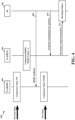
- FIG. 4 is a diagram 400 illustrating a potential issue associated with a transition of an ROHC compressor to a lower order state based on a feedback.
- the ROHC compressor 402 at the transmitting device (which may also be referred to as a first (wireless) device hereinafter) (e.g., a UE) may operate in the SO state.
- a number of packets (e.g., x packets) may have been compressed and stored in the buffer at the PDCP layer 404 of the transmitting device, while the transmitting device may be waiting for an uplink grant from the receiving device 406 (which may also be referred to as a second (wireless) device hereinafter) (e.g., a base station) so that the packets may be transmitted in uplink.
- a second (wireless) device e.g., a base station
- the ROHC compressor 402 may receive, at 408, an ROHC feedback from the receiving device 406.
- the ROHC feedback (e.g., a negative feedback) may indicate a transition to a lower order compression state, for example, from the SO state to the FO or the IR state.
- the compressed x packets have been compressed with the ROHC compressor 402 in the higher order state (e.g., the SO state)
- transmitting these previously compressed packets, at 412, to the receiving device 406 after the grant at 410 may result in a decoding failure at the receiving device 406.
- the decoding failure may in turn lead to a drop in data throughput.
- FIG. 5 is a diagram 500 illustrating a potential issue associated with a transition of an ROHC compressor to a higher order state based on a feedback.
- the ROHC compressor 502 at the transmitting device may operate in the IR or the FO state.
- a number of packets (e.g., x packets) may have been compressed and stored in the buffer at the PDCP layer 504 of the transmitting device, while the transmitting device may be waiting for an uplink grant from the receiving device 506 so that the packets may be transmitted in uplink.
- the ROHC compressor 502 may receive, at 508, an ROHC feedback from the receiving device 506.
- the ROHC feedback (e.g., a positive feedback) may indicate a transition to a higher order compression state, for example, from the IR or the FO state to the SO state.
- the compressed x packets have been compressed with the ROHC compressor 502 in the lower order state (e.g., the IR or the FO state)
- transmitting these previously compressed packets, at 512, to the receiving device 506 after the grant at 510 may result in a reduced compression efficiency as higher order compression could have been used.
- the reduced compression efficiency may correspond to a waste of bandwidth resources and transmit power.
- FIG. 6 is a communication flow diagram 600 of a method of wireless communication.
- FIG. 6 illustrates initial events that may be similar to those illustrated in FIG. 4 .
- the ROHC compressor 602 at the transmitting device may operate in the SO state.
- a number of packets (e.g., x packets) may have been compressed and stored in the buffer at the PDCP layer 604 of the transmitting device, while the transmitting device may be waiting for an uplink grant from the receiving device 606 so that the packets may be transmitted in uplink.
- the ROHC compressor 602 may receive, at 608, an ROHC feedback from the receiving device 606.
- the ROHC feedback (e.g., a negative feedback) may indicate a transition to a lower order compression state, for example, from the SO state to the FO or the IR state.
- the ROHC compressor 602 may provide a state change indication to the PDCP layer 604 of the transmitting device. Based on the state change indication, the entire set of the unsent x previously compressed packets may be discarded, and the corresponding uncompressed packets may be transmitted, at 614, instead to the receiving device 606 after the grant at 612. As the ROHC bearer may already have a context established for profile 0 for uncompressed packets, there may not be a decoding failure at the receiver. Once all the packets are transmitted as uncompressed packets, the transmitting device may restart with the IR state for all the CIDs to avoid further decompression/decoding failures.
- FIG. 7 is a communication flow diagram 700 of a method of wireless communication.
- FIG. 7 illustrates initial events that may be similar to those illustrated in FIG. 4 .
- the ROHC compressor 702 at the transmitting device may operate in the SO state.
- a number of packets (e.g., x packets) may have been compressed and stored in the buffer at the PDCP layer 704 of the transmitting device, while the transmitting device may be waiting for an uplink grant from the receiving device 706 so that the packets may be transmitted in uplink.
- the ROHC compressor 702 may receive, at 708, an ROHC feedback for one or more CIDs from the receiving device 706.
- the ROHC feedback (e.g., a negative feedback) for one or more CIDs may indicate a transition to a lower order compression state, for example, from the SO state to the FO or the IR state.
- Whether to transmit the previously compressed packets as uncompressed packets may be determined based on a comparison between a factor and a threshold.
- the factor may be calculated as the total number of previously compressed bytes divided by (/) the number of previously compressed bytes associated with the one or more CIDs associated with the ROHC feedback. If the factor is less than the threshold, at 710, the ROHC compressor 702 may provide a state change indication to the PDCP layer 704 of the transmitting device. Based on the state change indication, the entire set of the unsent x previously compressed packets may be discarded, and the corresponding uncompressed packets may be transmitted, at 714, to the receiving device 706 instead after the grant at 712.
- the previously compressed packets may be transmitted to the receiving device 706 in an unaltered state (i.e., as previously compressed packets with no change). It should be appreciated that there may be added overall overhead associated with making the decision on whether to transmit the packets as uncompressed packets.
- FIG. 8 is a communication flow diagram 800 of a method of wireless communication.
- FIG. 8 illustrates initial events that may be similar to those illustrated in FIG. 4 .
- the ROHC compressor at the transmitting device 802 may operate in the SO state.
- a number of packets (e.g., x packets) may have been compressed and stored in the buffer at the PDCP layer of the transmitting device 802, while the transmitting device 802 may be waiting for an uplink grant from the receiving device 804 so that the packets may be transmitted in uplink.
- the transmitting device 802 may receive, at 806, an ROHC feedback for one or more CIDs from the receiving device 804.
- the ROHC feedback (e.g., a negative feedback) for one or more CIDs may indicate a transition to a lower order compression state, for example, from the SO state to the FO or the IR state.
- the transmitting device 802 may discard the previously compressed y packets associated with the one or more CIDs associated with the ROHC feedback, and may transmit corresponding uncompressed packets to the receiving device 804 instead. Further, the transmitting device 802 may transmit the remaining previously compressed packets to the receiving device 804 in an unaltered state (i.e., as previously compressed packets with no change).
- FIG. 9 is a communication flow diagram 900 of a method of wireless communication.
- FIG. 9 illustrates initial events that may be similar to those illustrated in FIG. 4 .
- the ROHC compressor at the transmitting device 902 may operate in the SO state.
- a number of packets (e.g., x packets) may have been compressed and stored in the buffer at the PDCP layer of the transmitting device 902, while the transmitting device 902 may be waiting for an uplink grant from the receiving device 904 so that the packets may be transmitted in uplink.
- the transmitting device 902 may receive, at 906, an ROHC feedback for one or more CIDs from the receiving device 904.
- the ROHC feedback (e.g., a negative feedback) for one or more CIDs may indicate a transition to a lower order compression state, for example, from the SO state to the FO or the IR state.
- the transmitting device 902, and the ROHC compressor may recompress the packets associated with the one or more CIDs associated with the ROHC feedback based on the new lower order compression state. Thereafter, at 910, after the grant at 908, the transmitting device 902 may transmit the recompressed packets associated with the one or more CIDs associated with the ROHC feedback to the receiving device 904. Further, the transmitting device 902 may transmit the remaining previously compressed packets to the receiving device 904 in an unaltered state (i.e., as previously compressed packets with no change). It should be appreciated that when there are a large number of compressed packets, recompressing all the packets may have a slight performance impact, but the overall compression efficiency may be improved.
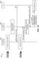
- FIG. 10 is a communication flow diagram 1000 of a method of wireless communication.
- FIG. 10 illustrates initial events that may be similar to those illustrated in FIG. 5 .
- the ROHC compressor 1002 at the transmitting device may operate in the IR or the FO state.
- a number of packets (e.g., x packets) may have been compressed and stored in the buffer at the PDCP layer 1004 of the transmitting device, while the transmitting device may be waiting for an uplink grant from the receiving device 1006 so that the packets may be transmitted in uplink.
- the ROHC compressor 1002 may receive, at 1008, an ROHC feedback for one or more CIDs from the receiving device 1006.
- the ROHC feedback (e.g., a positive feedback) for one or more CIDs may indicate a transition to a higher order compression state, for example, from the IR or the FO state to the SO state.
- the ROHC compressor 1002 may provide a state change indication to the PDCP layer 1004 of the transmitting device. Based on the state change indication, the PDCP layer 1004 of the transmitting device may recompress the packets associated with the one or more CIDs associated with the ROHC feedback based on the new higher order compression state. Thereafter, at 1014, after the grant for transmission of x packets at 1012, the transmitting device may transmit the recompressed packets associated with the one or more CIDs associated with the ROHC feedback to the receiving device 1006. Further, the transmitting device may transmit the remaining previously compressed packets to the receiving device 1006 in an unaltered state (i.e., as previously compressed packets with no change).
- a fewer total number (e.g., y) of packets may be transmitted at 1014, and the grant for x packets at 1012 may accommodate the whole transmission at 1014. It should be appreciated that when there are a large number of compressed packets, recompressing all the packets may have a slight performance impact, but the transmitting device (e.g., a UE) may save considerable transmit power and uplink resources.
- the number of packets in the recompressed subset of packets may be based on the threshold.
- the PDCP layer 1104 of the transmitting device may transmit, at 1114, the recompressed subset of packets associated with the one or more CIDs associated with the ROHC feedback to the receiving device 1106, and may transmit the remaining previously compressed packets to the receiving device 1106 in an unaltered state (i.e., as previously compressed packets with no change). If the factor is greaterthan the threshold, the entire set of previously compressed packets may be transmitted to the receiving device 706 in an unaltered state (i.e., as previously compressed packets with no change). It should be appreciated that there may be added overhead associated with making the decision on whether to recompress a subset of previously compressed packets.
- ROHC uplink data compression
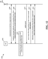
- FIG. 12 is a communication flow diagram 1200 of a method of wireless communication.
- the UE 1202 may also be referred to herein as a first device 1202, and the base station 1204 may also be referred to herein as a second device 1204. In other aspects, the roles of the UE and the base station may be reversed.
- the first device 1202 and the second device 1204 may communicate with each other in the first compression state.
- the second device 1204 may transmit to the first device 1202, and the first device 1202 may receive from the second device 1204, a feedback message indicative of a transition from a first compression state to a second compression state.
- the first device 1202 may transition, based on a state change indication corresponding to the feedback message, from the first compression state to the second compression state.
- the second device 1204 may transmit to the first device 1202, and the first device 1202 may receive from the second device 1204 an uplink grant for a transmission of a number of data packets.
- the first device 1202 may transmit to the second device 1204, and the second device 1204 may receive from the first device 1202, based on the transition from the first compression state to the second compression state, one or more first data packets that are previously compressed based on the first compression state or one or more second data packets that are uncompressed or recompressed based on the second compression state, the one or more second data packets being associated with the one or more first data packets.
- the first device 1202 may transmit to the second device 1204, and the second device 1204 may receive from the first device 1202, an indication of the transition from the first compression state to the second compression state.
- the one or more first data packets or the one or more second data packets may correspond to at least one of: TCP packets, UDP packets, RTP packets, or IP packets.
- the feedback message may be associated with one or more CIDs.
- the one or more first data packets or the one or more second data packets may correspond to buffered data packets associated with the one or more CIDs.
- the first device 1202 may transmit at 1214 the one or more second data packets to the second device 1204 as data packets recompressed based on the second compression state.
- the first compression state (e.g., the SO state) may be associated with a higher order than the second compression state (e.g., the IR or the FO state).
- the one or more first data packets or the one or more second data packets may correspond to an entire set of buffered data packets.
- the first device 1202 may transmit at 1214 the one or more second data packets to the second device 1204 as uncompressed data packets.
- the feedback message may be associated with one or more CIDs.
- the state change indication may be associated with a factor that is based on a total number of previously compressed bytes and a number of previously compressed bytes associated with the one or more CIDs.
- the one or more first data packets or the one or more second data packets may correspond to an entire set of buffered data packets.
- the first device 1202 may transmit at 1214 the one or more second data packets to the second device 1204 as uncompressed data packets when the factor is less than a threshold, and the first device 1202 may transmit at 1214 the one or more first data packets to the second device 1204 when the factor is greater than the threshold.
- the feedback message may be associated with one or more CIDs.
- the one or more first data packets or the one or more second data packets may correspond to buffered data packets associated with the one or more CIDs.
- the first device 1202 may transmit at 1214 the one or more second data packets to the second device 1204 as uncompressed data packets.
- the second compression state (e.g., the SO state) may be associated with a higher order than the first compression state (e.g., the IR or the FO state).
- the feedback message may be associated with one or more CIDs.
- the state change indication may be associated with a factor that is based on a total number of previously compressed bytes and a number of previously compressed bytes associated with the one or more CIDs.
- the one or more first data packets or the one or more second data packets may correspond to a subset of buffered data packets associated with the one or more CIDs. A number of data packets in the subset may be based on the factor.
- the first device 1202 may transmit at 1214 the one or more second data packets to the second device 1204 as data packets recompressed based on the second compression state when the factor is less than a threshold, and the first device 1202 may transmit at 1214 the one or more first data packets to the second device 1204 when the factor is greater than the threshold.
- FIG. 13 is a flowchart 1300 of a method of wireless communication.
- the method may be performed by a first wireless device (e.g., a UE) (e.g., the UE 104/350/1202; the apparatus 1702).
- the first wireless device may receive, from a second wireless device, a feedback message indicative of a transition from a first compression state to a second compression state.
- 1302 may be performed by the compression component 1740 in FIG. 17 .
- the first wireless device 1202 may receive, from a second wireless device 1204, a feedback message indicative of a transition from a first compression state to a second compression state.
- the first wireless device may transition, based on a state change indication corresponding to the feedback message, from the first compression state to the second compression state.
- 1304 may be performed by the compression component 1740 in FIG. 17 .
- the first wireless device 1202 may transition, based on a state change indication corresponding to the feedback message, from the first compression state to the second compression state.
- the first wireless device may transmit, to the second wireless device based on the transition from the first compression state to the second compression state, one or more first data packets that are previously compressed based on the first compression state or one or more second data packets that are uncompressed or recompressed based on the second compression state.
- the one or more second data packets may be associated with the one or more first data packets.
- 1306 may be performed by the compression component 1740 in FIG. 17 . Referring to FIG.
- the first wireless device 1202 may transmit, to the second wireless device 1204 based on the transition from the first compression state to the second compression state, one or more first data packets that are previously compressed based on the first compression state or one or more second data packets that are uncompressed or recompressed based on the second compression state.
- FIG. 14 is a flowchart 1400 of a method of wireless communication.
- the method may be performed by a UE (e.g., the UE 104/350/1202; the apparatus 1702).
- the first wireless device may receive, from a second wireless device, a feedback message indicative of a transition from a first compression state to a second compression state.
- 1404 may be performed by the compression component 1740 in FIG. 17 .
- the first wireless device 1202 may receive, from a second wireless device 1204, a feedback message indicative of a transition from a first compression state to a second compression state.
- the first wireless device may transition, based on a state change indication corresponding to the feedback message, from the first compression state to the second compression state.
- 1406 may be performed by the compression component 1740 in FIG. 17 .
- the first wireless device 1202 may transition, based on a state change indication corresponding to the feedback message, from the first compression state to the second compression state.
- the first wireless device may transmit, to the second wireless device based on the transition from the first compression state to the second compression state, one or more first data packets that are previously compressed based on the first compression state or one or more second data packets that are uncompressed or recompressed based on the second compression state.
- the one or more second data packets may be associated with the one or more first data packets.
- 1410 may be performed by the compression component 1740 in FIG. 17 . Referring to FIG.
- the first wireless device 1202 may transmit, to the second wireless device 1204 based on the transition from the first compression state to the second compression state, one or more first data packets that are previously compressed based on the first compression state or one or more second data packets that are uncompressed or recompressed based on the second compression state.
- the first wireless device may communicate with the second wireless device in the first compression state.
- 1402 may be performed by the compression component 1740 in FIG. 17 .
- the first wireless device 1202 may communicate with the second wireless device 1204 in the first compression state.
- the first wireless device may transmit, to the second wireless device, an indication of the transition from the first compression state to the second compression state.
- 1412 may be performed by the compression component 1740 in FIG. 17 .
- the first wireless device 1202 may transmit, to the second wireless device 1204, an indication of the transition from the first compression state to the second compression state.
- the first wireless device may receive, from the second wireless device, an uplink grant for a transmission of a number of data packets.
- 1408 may be performed by the compression component 1740 in FIG. 17 .
- the first wireless device 1202 may receive, from the second wireless device 1204, an uplink grant for a transmission of a number of data packets.
- the one or more first data packets or the one or more second data packets may correspond to at least one of: TCP packets, UDP packets, RTP packets, or IP packets.
- the first wireless device may be a UE and the second wireless device may be a base station.
- the feedback message may be associated with one or more CIDs.
- the one or more first data packets or the one or more second data packets may correspond to buffered data packets associated with the one or more CIDs.
- the one or more second data packets may be transmitted to the second wireless device as data packets recompressed based on the second compression state.
- the first compression state may be associated with a higher order than the second compression state.
- the one or more first data packets or the one or more second data packets may correspond to an entire set of buffered data packets.
- the one or more second data packets may be transmitted to the second wireless device as uncompressed data packets.
- the feedback message may be associated with one or more CIDs.
- the state change indication may be associated with a factor that is based on a total number of previously compressed bytes and a number of previously compressed bytes associated with the one or more CIDs.
- the one or more first data packets or the one or more second data packets may correspond to an entire set of buffered data packets.
- the one or more second data packets may be transmitted to the second wireless device as uncompressed data packets when the factor is less than a threshold, and the one or more first data packets may be transmitted to the second wireless device when the factor is greater than the threshold.
- the feedback message may be associated with one or more CIDs.
- the one or more first data packets or the one or more second data packets may correspond to buffered data packets associated with the one or more CIDs.
- the one or more second data packets may be transmitted to the second wireless device as uncompressed data packets.
- the second compression state may be associated with a higher order than the first compression state.
- the feedback message may be associated with one or more CIDs.
- the state change indication may be associated with a factor that is based on a total number of previously compressed bytes and a number of previously compressed bytes associated with the one or more CIDs.
- the one or more first data packets or the one or more second data packets may correspond to a subset of buffered data packets associated with the one or more CIDs. A number of data packets in the subset may be based on the factor.
- the one or more second data packets may be transmitted to the second wireless device as data packets recompressed based on the second compression state when the factor is less than a threshold, and the one or more first data packets may be transmitted to the second wireless device when the factor is greater than the threshold.
- FIG. 15 is a flowchart 1500 of a method of wireless communication.
- the method may be performed by a second wireless device (e.g., a base station) (e.g., the base station 102/180/310/1204; the apparatus 1802).
- the second wireless device may transmit, to a first wireless device, a feedback message indicative of a transition from a first compression state to a second compression state.
- 1502 may be performed by the compression component 1840 in FIG. 18 .
- the second wireless device 1204 may transmit, to a first wireless device 1202, a feedback message indicative of a transition from a first compression state to a second compression state.
- the second wireless device may receive, from the first wireless device based on the transition from the first compression state to the second compression state, one or more first data packets that are previously compressed based on the first compression state or one or more second data packets that are uncompressed or recompressed based on the second compression state.
- the one or more second data packets may be associated with the one or more first data packets.
- 1504 may be performed by the compression component 1840 in FIG. 18 . Referring to FIG.
- the second wireless device 1204 may receive, from the first wireless device 1202 based on the transition from the first compression state to the second compression state, one or more first data packets that are previously compressed based on the first compression state or one or more second data packets that are uncompressed or recompressed based on the second compression state.
- FIG. 16 is a flowchart 1600 of a method of wireless communication.
- the method may be performed by a second wireless device (e.g., a base station) (e.g., the base station 102/180/310/1204; the apparatus 1802).
- the second wireless device may transmit, to a first wireless device, a feedback message indicative of a transition from a first compression state to a second compression state.
- 1604 may be performed by the compression component 1840 in FIG. 18 .
- the second wireless device 1204 may transmit, to a first wireless device 1202, a feedback message indicative of a transition from a first compression state to a second compression state.
- the second wireless device may receive, from the first wireless device based on the transition from the first compression state to the second compression state, one or more first data packets that are previously compressed based on the first compression state or one or more second data packets that are uncompressed or recompressed based on the second compression state.
- the one or more second data packets may be associated with the one or more first data packets.
- 1608 may be performed by the compression component 1840 in FIG. 18 . Referring to FIG.
- the second wireless device 1204 may receive, from the first wireless device 1202 based on the transition from the first compression state to the second compression state, one or more first data packets that are previously compressed based on the first compression state or one or more second data packets that are uncompressed or recompressed based on the second compression state.
- the second wireless device may communicate with the first wireless device in the first compression state.
- 1602 may be performed by the compression component 1840 in FIG. 18 .
- the second wireless device 1204 may communicate with the first wireless device 1202 in the first compression state.
- the second wireless device may receive, from the first wireless device, an indication of the transition from the first compression state to the second compression state.
- 1610 may be performed by the compression component 1840 in FIG. 18 .
- the second wireless device 1204 may receive, from the first wireless device 1202, an indication of the transition from the first compression state to the second compression state.
- the second wireless device may transmit, to the first wireless device, an uplink grant for a transmission of a number of data packets.
- 1606 may be performed by the compression component 1840 in FIG. 18 .
- the second wireless device 1204 may transmit, to the first wireless device 1202, an uplink grant for a transmission of a number of data packets.
- the one or more first data packets or the one or more second data packets may correspond to at least one of: TCP packets, UDP packets, RTP packets, or IP packets.
- the first wireless device may be a UE and the second wireless device may be a base station.
- the feedback message may be associated with one or more CIDs.
- the one or more first data packets or the one or more second data packets may correspond to buffered data packets associated with the one or more CIDs.
- the one or more second data packets may be received from the first wireless device as data packets recompressed based on the second compression state.
- the first compression state may be associated with a higher order than the second compression state.
- the one or more first data packets or the one or more second data packets may correspond to an entire set of buffered data packets.
- the one or more second data packets may be received from the first wireless device as uncompressed data packets.
- the feedback message may be associated with one or more CIDs.
- a state change indication may be associated with a factor that is based on a total number of previously compressed bytes and a number of previously compressed bytes associated with the one or more CIDs.
- the one or more first data packets or the one or more second data packets may correspond to an entire set of buffered data packets.
- the one or more second data packets may be received from the first wireless device as uncompressed data packets when the factor is less than a threshold, and the one or more first data packets may be received from the first wireless device when the factor is greater than the threshold.
- the feedback message may be associated with one or more CIDs.
- the one or more first data packets or the one or more second data packets may correspond to buffered data packets associated with the one or more CIDs.
- the one or more second data packets may be received from the first wireless device as uncompressed data packets.
- the second compression state may be associated with a higher order than the first compression state.
- the feedback message may be associated with one or more CIDs.
- a state change indication may be associated with a factor that is based on a total number of previously compressed bytes and a number of previously compressed bytes associated with the one or more CIDs.
- the one or more first data packets or the one or more second data packets may correspond to a subset of buffered data packets associated with the one or more CIDs. A number of data packets in the subset may be based on the factor.
- the one or more second data packets may be received from the first wireless device as data packets recompressed based on the second compression state when the factor is less than a threshold, and the one or more first data packets may be received from the first wireless device when the factor is greater than the threshold.
- FIG. 17 is a diagram 1700 illustrating an example of a hardware implementation for an apparatus 1702.
- the apparatus 1702 is a UE and includes a cellular baseband processor 1704 (also referred to as a modem) coupled to a cellular RF transceiver 1722 and one or more subscriber identity modules (SIM) cards 1720, an application processor 1706 coupled to a secure digital (SD) card 1708 and a screen 1710, a Bluetooth module 1712, a wireless local area network (WLAN) module 1714, a Global Positioning System (GPS) module 1716, and a power supply 1718.
- the cellular baseband processor 1704 communicates through the cellular RF transceiver 1722 with the UE 104 and/or BS 102/180.
- the cellular baseband processor 1704 may include a computer-readable medium / memory.
- the computer-readable medium / memory may be non-transitory.
- the cellular baseband processor 1704 is responsible for general processing, including the execution of software stored on the computer-readable medium / memory.
- the software when executed by the cellular baseband processor 1704, causes the cellular baseband processor 1704 to perform the various functions described supra.
- the computer-readable medium / memory may also be used for storing data that is manipulated by the cellular baseband processor 1704 when executing software.
- the cellular baseband processor 1704 further includes a reception component 1730, a communication manager 1732, and a transmission component 1734.
- the communication manager 1732 includes the one or more illustrated components.
- the components within the communication manager 1732 may be stored in the computer-readable medium / memory and/or configured as hardware within the cellular baseband processor 1704.
- the cellular baseband processor 1704 may be a component of the UE 350 and may include the memory 360 and/or at least one of the TX processor 368, the RX processor 356, and the controller/processor 359.
- the apparatus 1702 may be a modem chip and include just the baseband processor 1704, and in another configuration, the apparatus 1702 may be the entire UE (e.g., see 350 of FIG. 3 ) and include the aforediscussed additional modules of the apparatus 1702.
- the communication manager 1732 includes a compression component 1740 that may be configured to communicate with the second wireless device in the first compression state, e.g., as described in connection with 1402 in FIG. 14 .
- the compression component 1740 may be further configured to receive, from a second wireless device, a feedback message indicative of a transition from a first compression state to a second compression state, e.g., as described in connection with 1302 in FIG. 13 and 1404 in FIG. 14 .
- the compression component 1740 may be further configured to transition, based on a state change indication corresponding to the feedback message, from the first compression state to the second compression state, e.g., as described in connection with 1304 in FIG. 13 and 1406 in FIG. 14 .
- the compression component 1740 may be further configured to receive, from the second wireless device, an uplink grant for a transmission of a number of data packets, e.g., as described in connection with 1408 in FIG. 14 .
- the compression component 1740 may be further configured to transmit, to the second wireless device based on the transition from the first compression state to the second compression state, one or more first data packets that are previously compressed based on the first compression state or one or more second data packets that are uncompressed or recompressed based on the second compression state, the one or more second data packets being associated with the one or more first data packets, e.g., as described in connection with 1306 in FIG. 13 and 1410 in FIG. 14 .
- the compression component 1740 may be further configured to transmit, to the second wireless device, an indication of the transition from the first compression state to the second compression state, e.g., as described in connection with 1412 in FIG. 14 .
- the apparatus may include additional components that perform each of the blocks of the algorithm in the aforementioned flowcharts of FIGs. 12-14 .
- each block in the aforementioned flowcharts of FIGs. 12-14 may be performed by a component and the apparatus may include one or more of those components.
- the components may be one or more hardware components specifically configured to carry out the stated processes/algorithm, implemented by a processor configured to perform the stated processes/algorithm, stored within a computer-readable medium for implementation by a processor, or some combination thereof.
- the apparatus 1702 includes means for receiving, from a second wireless device, a feedback message indicative of a transition from a first compression state to a second compression state.
- the apparatus 1702 may include means for transitioning, based on a state change indication corresponding to the feedback message, from the first compression state to the second compression state.
- the apparatus 1702 may include means for transmitting, to the second wireless device based on the transition from the first compression state to the second compression state, one or more first data packets that are previously compressed based on the first compression state or one or more second data packets that are uncompressed or recompressed based on the second compression state, the one or more second data packets being associated with the one or more first data packets.
- the apparatus 1702 may further include means for communicating with the second wireless device in the first compression state. In one configuration, the apparatus 1702 may further include means for transmitting, to the second wireless device, an indication of the transition from the first compression state to the second compression state. In one configuration, the apparatus 1702 may further include means for receiving, from the second wireless device, an uplink grant for a transmission of a number of data packets. In one configuration, the one or more first data packets or the one or more second data packets may correspond to at least one of: TCP packets, UDP packets, RTP packets, or IP packets. In one configuration, the first wireless device may be a UE and the second wireless device may be a base station.
- the feedback message may be associated with one or more CIDs.
- the one or more first data packets or the one or more second data packets may correspond to buffered data packets associated with the one or more CIDs.
- the one or more second data packets may be transmitted to the second wireless device as data packets recompressed based on the second compression state.
- the first compression state may be associated with a higher order than the second compression state.
- the one or more first data packets or the one or more second data packets may correspond to an entire set of buffered data packets.
- the one or more second data packets may be transmitted to the second wireless device as uncompressed data packets.
- the feedback message may be associated with one or more CIDs.
- the state change indication may be associated with a factor that is based on a total number of previously compressed bytes and a number of previously compressed bytes associated with the one or more CIDs.
- the one or more first data packets or the one or more second data packets may correspond to an entire set of buffered data packets.
- the one or more second data packets may be transmitted to the second wireless device as uncompressed data packets when the factor is less than a threshold, and the one or more first data packets may be transmitted to the second wireless device when the factor is greater than the threshold.
- the feedback message may be associated with one or more CIDs.
- the one or more first data packets or the one or more second data packets may correspond to buffered data packets associated with the one or more CIDs.
- the one or more second data packets may be transmitted to the second wireless device as uncompressed data packets.
- the second compression state may be associated with a higher order than the first compression state.
- the feedback message may be associated with one or more CIDs.
- the state change indication may be associated with a factor that is based on a total number of previously compressed bytes and a number of previously compressed bytes associated with the one or more CIDs.
- the one or more first data packets or the one or more second data packets may correspond to a subset of buffered data packets associated with the one or more CIDs. A number of data packets in the subset may be based on the factor.
- the one or more second data packets may be transmitted to the second wireless device as data packets recompressed based on the second compression state when the factor is less than a threshold, and the one or more first data packets may be transmitted to the second wireless device when the factor is greater than the threshold.
- the aforementioned means may be one or more of the aforementioned components of the apparatus 1702 configured to perform the functions recited by the aforementioned means.
- the apparatus 1702 may include the TX Processor 368, the RX Processor 356, and the controller/processor 359.
- the aforementioned means may be the TX Processor 368, the RX Processor 356, and the controller/processor 359 configured to perform the functions recited by the aforementioned means.
- FIG. 18 is a diagram 1800 illustrating an example of a hardware implementation for an apparatus 1802.
- the apparatus 1802 is a BS and includes a baseband unit 1804.
- the baseband unit 1804 may communicate through a cellular RF transceiver 1822 with the UE 104.
- the baseband unit 1804 may include a computer-readable medium / memory.
- the baseband unit 1804 is responsible for general processing, including the execution of software stored on the computer-readable medium / memory.
- the software when executed by the baseband unit 1804, causes the baseband unit 1804 to perform the various functions described supra.
- the computer-readable medium / memory may also be used for storing data that is manipulated by the baseband unit 1804 when executing software.
- the baseband unit 1804 further includes a reception component 1830, a communication manager 1832, and a transmission component 1834.
- the communication manager 1832 includes the one or more illustrated components.
- the components within the communication manager 1832 may be stored in the computer-readable medium / memory and/or configured as hardware within the baseband unit 1804.
- the baseband unit 1804 may be a component of the BS 310 and may include the memory 376 and/or at least one of the TX processor 316, the RX processor 370, and the controller/processor 375.
- the communication manager 1832 includes a compression component 1840 that may be configured to communicate with the first wireless device in the first compression state, e.g., as described in connection with 1602 in FIG. 16 .
- the compression component 1840 may be further configured to transmit, to a first wireless device, a feedback message indicative of a transition from a first compression state to a second compression state, e.g., as described in connection with 1502 in FIG. 15 and 1604 in FIG. 16 .
- the compression component 1840 may be further configured to transmit, to the first wireless device, an uplink grant for a transmission of a number of data packets, e.g., as described in connection with 1606 in FIG. 16 .
- the compression component 1840 may be further configured to receive, from the first wireless device based on the transition from the first compression state to the second compression state, one or more first data packets that are previously compressed based on the first compression state or one or more second data packets that are uncompressed or recompressed based on the second compression state, the one or more second data packets being associated with the one or more first data packets, e.g., as described in connection with 1504 in FIG. 15 and 1608 in FIG. 16 .
- the compression component 1840 may be further configured to receive, from the first wireless device, an indication of the transition from the first compression state to the second compression state, e.g., as described in connection with 1610 in FIG. 16 .
- the apparatus may include additional components that perform each of the blocks of the algorithm in the aforementioned flowcharts of FIGs. 12 , 15 , and 16 .
- each block in the aforementioned flowcharts of FIGs. 12 , 15 , and 16 may be performed by a component and the apparatus may include one or more of those components.
- the components may be one or more hardware components specifically configured to carry out the stated processes/algorithm, implemented by a processor configured to perform the stated processes/algorithm, stored within a computer-readable medium for implementation by a processor, or some combination thereof.
- the apparatus 1802 includes means for transmitting, to a first wireless device, a feedback message indicative of a transition from a first compression state to a second compression state.
- the apparatus 1802 may include means for receiving, from the first wireless device based on the transition from the first compression state to the second compression state, one or more first data packets that are previously compressed based on the first compression state or one or more second data packets that are uncompressed or recompressed based on the second compression state, the one or more second data packets being associated with the one or more first data packets.
- the apparatus 1802 may further include means for communicating with the first wireless device in the first compression state. In one configuration, the apparatus 1802 may further include means for receiving, from the first wireless device, an indication of the transition from the first compression state to the second compression state. In one configuration, the apparatus 1802 may further include means for transmitting, to the first wireless device, an uplink grant for a transmission of a number of data packets. In one configuration, the one or more first data packets or the one or more second data packets may correspond to at least one of: TCP packets, UDP packets, RTP packets, or IP packets. In one configuration, the first wireless device may be a UE and the second wireless device may be a base station.
- the feedback message may be associated with one or more CIDs.
- the one or more first data packets or the one or more second data packets may correspond to buffered data packets associated with the one or more CIDs.
- the one or more second data packets may be received from the first wireless device as data packets recompressed based on the second compression state.
- the first compression state may be associated with a higher order than the second compression state.
- the one or more first data packets or the one or more second data packets may correspond to an entire set of buffered data packets.
- the one or more second data packets may be received from the first wireless device as uncompressed data packets.
- the feedback message may be associated with one or more CIDs.
- a state change indication may be associated with a factor that is based on a total number of previously compressed bytes and a number of previously compressed bytes associated with the one or more CIDs.
- the one or more first data packets or the one or more second data packets may correspond to an entire set of buffered data packets.
- the one or more second data packets may be received from the first wireless device as uncompressed data packets when the factor is less than a threshold, and the one or more first data packets may be received from the first wireless device when the factor is greater than the threshold.
- the feedback message may be associated with one or more CIDs.
- the one or more first data packets or the one or more second data packets may correspond to buffered data packets associated with the one or more CIDs.
- the one or more second data packets may be received from the first wireless device as uncompressed data packets.
- the second compression state may be associated with a higher order than the first compression state.
- the feedback message may be associated with one or more CIDs.
- a state change indication may be associated with a factor that is based on a total number of previously compressed bytes and a number of previously compressed bytes associated with the one or more CIDs.
- the one or more first data packets or the one or more second data packets may correspond to a subset of buffered data packets associated with the one or more CIDs. A number of data packets in the subset may be based on the factor.
- the one or more second data packets may be received from the first wireless device as data packets recompressed based on the second compression state when the factor is less than a threshold, and the one or more first data packets may be received from the first wireless device when the factor is greater than the threshold.
- the aforementioned means may be one or more of the aforementioned components of the apparatus 1802 configured to perform the functions recited by the aforementioned means.
- the apparatus 1802 may include the TX Processor 316, the RX Processor 370, and the controller/processor 375.
- the aforementioned means may be the TX Processor 316, the RX Processor 370, and the controller/processor 375 configured to perform the functions recited by the aforementioned means.
- the second wireless device may transmit, to the first wireless device, a feedback message indicative of a transition from a first compression state to a second compression state.
- the first wireless device may transition, based on a state change indication corresponding to the feedback message, from the first compression state to the second compression state.
- the first wireless device may transmit, to the second wireless device based on the transition from the first compression state to the second compression state, one or more first data packets that are previously compressed based on the first compression state or one or more second data packets that are uncompressed or recompressed based on the second compression state.
- the one or more second data packets being associated with the one or more first data packets.
- the decoding failure may be avoided when a compression bearer is transitioned from a higher order compression state to a lower order compression state, and the compression efficiency may be improved when the compression bearer is transitioned from a lower order compression state to a higher order compression state.
- Different aspects may be associated with different performance profiles including different compression efficiencies, different bandwidth resource utilizations, and/or different transmit power savings.
- Combinations such as "at least one of A, B, or C,” “one or more of A, B, or C,” “at least one of A, B, and C,” “one or more of A, B, and C,” and "A, B, C, or any combination thereof” include any combination of A, B, and/or C, and may include multiples of A, multiples of B, or multiples of C.
- combinations such as “at least one of A, B, or C,” “one or more of A, B, or C,” “at least one of A, B, and C,” “one or more of A, B, and C,” and “A, B, C, or any combination thereof” may be A only, B only, C only, A and B, A and C, B and C, or A and B and C, where any such combinations may contain one or more member or members of A, B, or C.
- nothing disclosed herein is intended to be dedicated to the public regardless of whether such disclosure is explicitly recited in the claims.
Landscapes
- Engineering & Computer Science (AREA)
- Multimedia (AREA)
- Computer Networks & Wireless Communication (AREA)
- Signal Processing (AREA)
- Computer Security & Cryptography (AREA)
- Business, Economics & Management (AREA)
- General Business, Economics & Management (AREA)
- Theoretical Computer Science (AREA)
- Mobile Radio Communication Systems (AREA)
Claims (15)
- Eine Vorrichtung (1700) für eine drahtlose Kommunikation an einem ersten drahtlosen Gerät, wobei die Vorrichtung (1700) aufweist:einen Speicher (1708), undwenigstens einen Prozessor (1706), der mit dem Speicher (1708) gekoppelt ist und konfiguriert ist zum:Empfangen, von einem zweiten drahtlosen Gerät, einer Rückmeldungsnachricht, die einen Übergang von einem ersten Kompressionszustand zu einem zweiten Kompressionszustand angibt, wobei der erste Kompressionszustand mit einer höheren Ordnung assoziiert ist als der zweite Kompressionszustand,Übergehen, basierend auf einer Zustandsänderungsangabe in Entsprechung zu der Rückmeldungsnachricht, von dem ersten Kompressionszustand zu dem zweiten Kompressionszustand, undSenden, an das zweite drahtlose Gerät und basierend auf dem Übergang von dem ersten Kompressionszustand zu dem zweiten Kompressionszustand, eines oder mehrerer erster Datenpakete, die zuvor basierend auf dem ersten Kompressionszustand komprimiert wurden, oder eines oder mehrerer zweiter Datenpakete, die basierend auf dem zweiten Kompressionszustand unkomprimiert oder erneut komprimiert sind, wobei das eine oder die mehreren zweiten Datenpakete mit der gleichen Kompressionskomponente assoziiert sind wie das eine oder die mehreren ersten Datenpakete,dadurch gekennzeichnet, dass die Rückmeldungsnachricht mit einer oder mehreren Kontextkennungen (Context Identifiers bzw. CIDs) assoziiert ist und die Zustandsänderungsangabe mit einem Faktor assoziiert ist, der auf der Gesamtanzahl von zuvor komprimierten Bytes und auf der Anzahl von zuvor komprimierten und mit der einen oder den mehreren CIDs assoziierten Bytes basiert, wobei das eine oder die mehreren ersten Datenpakete oder das eine oder die mehreren zweiten Datenpakete einem gesamten Satz von gepufferten Datenpaketen entsprechen, wobei das eine oder die mehreren zweiten Datenpakete an das zweite drahtlose Gerät als unkomprimierte Datenpakete gesendet werden, wenn der Faktor kleiner als ein Schwellwert ist, und wobei das eine oder die mehreren ersten Datenpakete an das zweite drahtlose Gerät gesendet werden, wenn der Faktor größer als der Schwellwert ist.
- Vorrichtung nach Anspruch 1, wobei der wenigstens eine Prozessor weiterhin konfiguriert ist zum:
Kommunizieren mit dem zweiten drahtlosen Gerät in dem ersten Kompressionszustand. - Vorrichtung nach Anspruch 1, wobei der wenigstens eine Prozessor weiterhin konfiguriert ist zum:
Senden, an das zweite drahtlose Gerät, einer Angabe des Übergangs von dem ersten Kompressionszustand zu dem zweiten Kompressionszustand. - Vorrichtung nach Anspruch 1, wobei der wenigstens eine Prozessor weiterhin konfiguriert ist zum:
Empfangen, von dem zweiten drahtlosen Gerät, einer Aufwärtsstreckegewährung für eine Sendung einer Anzahl von Datenpaketen. - Vorrichtung nach Anspruch 1, wobei das eine oder die mehreren ersten Datenpakete oder das eine oder die mehreren zweiten Datenpakete wenigstens einem der Folgenden entsprechen: TCP (Transmission Control Protocol)-Paketen, UDP (User Datagram Protocol)-Paketen, RTP (Real-Time Transport Protocol)-Paketen oder IP (Internet Protocol)-Paketen.
- Vorrichtung nach Anspruch 1, wobei das erste drahtlose Gerät ein Benutzergerät (User Equipment bzw. UE) ist und das zweite drahtlose Gerät eine Basisstation ist.
- Eine Vorrichtung (1700) für eine drahtlose Kommunikation an einem ersten drahtlosen Gerät, wobei die Vorrichtung (1700) aufweist:einen Speicher (1708), undwenigstens einen Prozessor (1706), der mit dem Speicher (1708) gekoppelt ist und konfiguriert ist zum:Empfangen, von einem zweiten drahtlosen Gerät, einer Rückmeldungsnachricht, die einen Übergang von einem ersten Kompressionszustand zu einem zweiten Kompressionszustand angibt, wobei der zweite Kompressionszustand mit einer höheren Ordnung assoziiert ist als der erste Kompressionszustand,Übergehen, basierend auf einer Zustandsänderungsangabe in Entsprechung zu der Rückmeldungsnachricht, von dem ersten Kompressionszustand zu dem zweiten Kompressionszustand, undSenden, an das zweite drahtlose Gerät und basierend auf dem Übergang von dem ersten Kompressionszustand zu dem zweiten Kompressionszustand, eines oder mehrerer erster Datenpakete, die zuvor basierend auf dem ersten Kompressionszustand komprimiert wurden, oder eines oder mehrerer zweiter Datenpakete, die basierend auf dem zweiten Kompressionszustand unkomprimiert oder erneut komprimiert sind, wobei das eine oder die mehreren zweiten Datenpakete mit der gleichen Kompressionskomponente assoziiert sind wie das eine oder die mehreren ersten Datenpakete,dadurch gekennzeichnet, dass die Rückmeldungsnachricht mit einer oder mehreren Kontextkennungen (Context Identifiers bzw. CI) assoziiert ist und die Zustandsänderungsangabe mit einem Faktor assoziiert ist, der auf der Gesamtanzahl von zuvor komprimierten Bytes und auf der Anzahl von zuvor komprimierten und mit der einen oder den mehreren CIDs assoziierten Bytes basiert, wobei das eine oder die mehreren ersten Datenpakete oder das eine oder die mehreren zweiten Datenpakete einem Teilsatz von gepufferten und mit der einen oder den mehreren CIDs assoziierten Datenpaketen entsprechen und wobei die Anzahl von Datenpaketen in dem Teilsatz auf dem Faktor basiert, wobei das eine oder die mehreren zweiten Datenpakete an das zweite drahtlose Gerät als basierend auf dem zweiten Kompressionszustand erneut komprimierte Datenpakete gesendet werden, wenn der Faktor kleiner als ein Schwellwert ist, und wobei das eine oder die mehreren ersten Datenpakete an das zweite drahtlose Gerät gesendet werden, wenn der Faktor größer als der Schwellwert ist.
- Ein Verfahren (1300) für eine drahtlose Kommunikation an einem ersten drahtlosen Gerät, wobei das Verfahren (1300) aufweist:Empfangen (1302), von einem zweiten drahtlosen Gerät, einer Rückmeldungsnachricht, die einen Übergang von einem ersten Kompressionszustand zu einem zweiten Kompressionszustand angibt, wobei der erste Kompressionszustand mit einer höheren Ordnung assoziiert ist als der zweite Kompressionszustand,Übergehen (1304), basierend auf einer Zustandsänderungsangabe in Entsprechung zu der Rückmeldungsnachricht, von dem ersten Kompressionszustand zu dem zweiten Kompressionszustand, undSenden (1306), an das zweite drahtlose Gerät und basierend auf dem Übergang von dem ersten Kompressionszustand zu dem zweiten Kompressionszustand, eines oder mehrerer erster Datenpakete, die basierend auf dem ersten Kompressionszustand zuvor komprimiert wurden, oder eines oder mehrerer zweiter Datenpakete, die basierend auf dem zweiten Kompressionszustand unkomprimiert oder erneut komprimiert sind, wobei das eine oder die mehreren zweiten Datenpakete mit der gleichen Kompressionskomponente assoziiert sind wie das eine oder die mehreren ersten Datenpakete,dadurch gekennzeichnet, dass die Rückmeldungsnachricht mit einer oder mehreren Kontextkennungen (Context Identifiers bzw. CIDs) assoziiert ist und die Zustandsänderungsangabe mit einem Faktor assoziiert ist, der auf der Gesamtanzahl von zuvor komprimierten Bytes und auf der Anzahl von zuvor komprimierten und mit der einen oder den mehreren CIDs assoziierten Bytes basiert, wobei das eine oder die mehreren ersten Datenpakete oder das eine oder die mehreren zweiten Datenpakete einem gesamten Satz von gepufferten Datenpaketen entsprechen, wobei das eine oder die mehreren zweiten Datenpakete an das zweite drahtlose Gerät als unkomprimierte Datenpakete gesendet werden, wenn der Faktor kleiner als ein Schwellwert ist, und wobei das eine oder die mehreren ersten Datenpakete an das zweite drahtlose Gerät gesendet werden, wenn der Faktor größer als der Schwellwert ist.
- Ein Verfahren (1300) für eine drahtlose Kommunikation an einem ersten drahtlosen Gerät, wobei das Verfahren (1300) aufweist:Empfangen (1302), von einem zweiten drahtlosen Gerät, einer Rückmeldungsnachricht, die einen Übergang von einem ersten Kompressionszustand zu einem zweiten Kompressionszustand angibt, wobei der zweite Kompressionszustand mit einer höheren Ordnung assoziiert ist als der erste Kompressionszustand,Übergehen (1304), basierend auf einer Zustandsänderungsangabe in Entsprechung zu der Rückmeldungsnachricht, von dem ersten Kompressionszustand zu dem zweiten Kompressionszustand, undSenden (1306), an das zweite drahtlose Gerät und basierend auf dem Übergang von dem ersten Kompressionszustand zu dem zweiten Kompressionszustand, eines oder mehrerer erster Datenpakete, die zuvor basierend auf dem ersten Kompressionszustand komprimiert wurden, oder eines oder mehrerer zweiter Datenpakete, die basierend auf dem zweiten Kompressionszustand unkomprimiert oder erneut komprimiert sind, wobei das eine oder die mehreren zweiten Datenpakete mit der gleichen Kompressionskomponente assoziiert sind wie das eine oder die mehreren ersten Datenpakete,dadurch gekennzeichnet, dass die Rückmeldungsnachricht mit einer oder mehreren Kontextkennungen (Context Identifiers bzw. CIDs) assoziiert ist und die Zustandsänderungsangabe mit einem Faktor assoziiert ist, der auf der Gesamtanzahl von zuvor komprimierten Bytes und auf der Anzahl von zuvor komprimierten und mit der einen oder den mehreren CIDs assoziierten Bytes basiert, wobei das eine oder die mehreren ersten Datenpakete oder das eine oder die mehreren zweiten Datenpakete einem Teilsatz von gepufferten und mit der einen oder den mehreren CIDs assoziierten Datenpaketen entsprechen und wobei die Anzahl von Datenpaketen in dem Teilsatz auf dem Faktor basiert, wobei das eine oder die mehreren zweiten Datenpakete an das zweite drahtlose Gerät als basierend auf dem zweiten Kompressionszustand erneut komprimierte Datenpakete gesendet werden, wenn der Faktor kleiner als ein Schwellwert ist, und wobei das eine oder die mehreren ersten Datenpakete an das zweite drahtlose Gerät gesendet werden, wenn der Faktor größer als der Schwellwert ist.
- Eine Vorrichtung (1700) für eine drahtlose Kommunikation an einem zweiten drahtlosen Gerät, wobei die Vorrichtung (1700) aufweist:einen Speicher (1708), undwenigstens einen Prozessor (1706), der mit dem Speicher (1708) gekoppelt ist und konfiguriert ist zum:Senden, an ein erstes drahtloses Gerät, einer Rückmeldungsnachricht, die einen Übergang von einem ersten Kompressionszustand zu einem zweiten Kompressionszustand angibt, wobei der erste Kompressionszustand mit einer höheren Ordnung assoziiert ist als der zweite Kompressionszustand, undEmpfangen, von dem ersten drahtlosen Gerät und basierend auf dem Übergang von dem ersten Kompressionszustand zu dem zweiten Kompressionszustand, eines oder mehrerer erster Datenpakete, die zuvor basierend auf dem ersten Kompressionszustand komprimiert wurden, oder eines oder mehrerer zweiter Datenpakete, die basierend auf dem zweiten Kompressionszustand unkomprimiert oder erneut komprimiert sind, wobei das eine oder die mehreren zweiten Datenpakete mit der gleichen Kompressionskomponente assoziiert sind wie das eine oder die mehreren ersten Datenpakete,dadurch gekennzeichnet, dass die Rückmeldungsnachricht mit einer oder mehreren Kontextkennungen (Context Identifiers bzw. CIDs) assoziiert ist und eine Zustandsänderungsangabe mit einem Faktor assoziiert ist, der auf der Gesamtanzahl von zuvor komprimierten Bytes und auf der Anzahl von zuvor komprimierten und mit der einen oder den mehreren CIDs assoziierten Bytes basiert, wobei das eine oder die mehreren ersten Datenpakete oder das eine oder die mehreren zweiten Datenpakete einem gesamten Satz von gepufferten Datenpaketen entsprechen, wobei das eine oder die mehreren zweiten Datenpakete von dem ersten drahtlosen Gerät als unkomprimierte Datenpakete empfangen werden, wenn der Faktor kleiner als ein Schwellwert ist, und wobei das eine oder die mehreren ersten Datenpakete von dem ersten drahtlosen Gerät empfangen werden, wenn der Faktor größer als der Schwellwert ist.
- Vorrichtung nach Anspruch 10, wobei der wenigstens eine Prozessor weiterhin konfiguriert ist zum:
Kommunizieren mit dem ersten drahtlosen Gerät in dem ersten Kompressionszustand. - Vorrichtung nach Anspruch 10, wobei der wenigstens eine Prozessor weiterhin konfiguriert ist zum:
Empfangen, von dem ersten drahtlosen Gerät, einer Angabe des Übergangs von dem ersten Kompressionszustand zu dem zweiten Kompressionszustand. - Eine Vorrichtung (1700) für eine drahtlose Kommunikation an einem zweiten drahtlosen Gerät, wobei die Vorrichtung (1700) aufweist:einen Speicher (1708), undwenigstens einen Prozessor (1706), der mit dem Speicher (1708) gekoppelt ist und konfiguriert ist zum:Senden, an ein erstes drahtloses Gerät, einer Rückmeldungsnachricht, die einen Übergang von einem ersten Kompressionszustand zu einem zweiten Kompressionszustand angibt, wobei der zweite Kompressionszustand mit einer höheren Ordnung assoziiert ist als der erste Kompressionszustand, undEmpfangen, von dem ersten drahtlosen Gerät und basierend auf dem Übergang von dem ersten Kompressionszustand zu dem zweiten Kompressionszustand, eines oder mehrerer erster Datenpakete, die basierend auf dem ersten Kompressionszustand zuvor komprimiert wurden, oder eines oder mehrerer zweiter Datenpakete, die basierend auf dem zweiten Kompressionszustand unkomprimiert oder erneut komprimiert sind, wobei das eine oder die mehreren zweiten Datenpakete mit der gleichen Kompressionskomponente assoziiert sind wie das eine oder die mehreren ersten Datenpakete,dadurch gekennzeichnet, dass die Rückmeldungsnachricht mit einer oder mehreren Kontextkennungen (Context Identifiers bzw. CIDs) assoziiert ist und die Zustandsänderungsangabe mit einem Faktor assoziiert ist, der auf der Gesamtanzahl von zuvor komprimierten Bytes und auf der Anzahl von zuvor komprimierten und mit der einen oder den mehreren CIDs assoziierten Bytes basiert, wobei das eine oder die mehreren ersten Datenpakete oder das eine oder die mehreren zweiten Datenpakete einem Teilsatz von gepufferten und mit der einen oder den mehreren CIDs assoziierten Datenpaketen entsprechen und wobei die Anzahl von Datenpaketen in dem Teilsatz auf dem Faktor basiert, wobei das eine oder die mehreren zweiten Datenpakete von dem ersten drahtlosen Gerät als basierend auf dem zweiten Kompressionszustand erneut komprimierte Datenpakete empfangen werden, wenn der Faktor kleiner als ein Schwellwert ist, und wobei das eine oder die mehreren ersten Datenpakete von dem ersten drahtlosen Gerät empfangen werden, wenn der Faktor größer als der Schwellwert ist.
- Ein Verfahren (1500) für eine drahtlose Kommunikation an einem zweiten drahtlosen Gerät, wobei das Verfahren (1500) aufweist:Senden (1502), an ein erstes drahtloses Gerät, einer Rückmeldungsnachricht, die einen Übergang von einem ersten Kompressionszustand zu einem zweiten Kompressionszustand angibt, wobei der erste Kompressionszustand mit einer höheren Ordnung assoziiert ist als der zweite Kompressionszustand, undEmpfangen (1504), von dem ersten drahtlosen Gerät und basierend auf dem Übergang von dem ersten Kompressionszustand zu dem zweiten Kompressionszustand, eines oder mehrerer erster Datenpakete, die basierend auf dem ersten Kompressionszustand zuvor komprimiert wurden, oder eines oder mehrerer zweiter Datenpakete, die basierend auf dem zweiten Kompressionszustand unkomprimiert oder erneut komprimiert sind, wobei das eine oder die mehreren zweiten Datenpakete mit der gleichen Kompressionskomponente assoziiert sind wie das eine oder die mehreren ersten Datenpakete,dadurch gekennzeichnet, dass die Rückmeldungsnachricht mit einer oder mehreren Kontextkennungen (Context Identifiers bzw. CIDs) assoziiert ist und eine Zustandsänderungsangabe mit einem Faktor assoziiert ist, der auf der Gesamtanzahl von zuvor komprimierten Bytes und auf der Anzahl von zuvor komprimierten und mit der einen oder den mehreren CIDs assoziierten Bytes basiert, wobei das eine oder die mehreren ersten Datenpakete oder das eine oder die mehreren zweiten Datenpakete einem gesamten Satz von gepufferten Datenpaketen entsprechen, wobei das eine oder die mehreren zweiten Datenpakete von dem ersten drahtlosen Gerät als unkomprimierte Datenpakete empfangen werden, wenn der Faktor kleiner als ein Schwellwert ist, und wobei das eine oder die mehreren ersten Datenpakete von dem ersten drahtlosen Gerät empfangen werden, wenn der Faktor größer als der Schwellwert ist.
- Ein Verfahren (1500) für eine drahtlose Kommunikation an einem zweiten drahtlosen Gerät, wobei das Verfahren (1500) aufweist:Senden (1502), an ein erstes drahtloses Gerät, einer Rückmeldungsnachricht, die einen Übergang von einem ersten Kompressionszustand zu einem zweiten Kompressionszustand angibt, wobei der zweite Kompressionszustand mit einer höheren Ordnung assoziiert ist als der erste Kompressionszustand, undEmpfangen (1504), von dem ersten drahtlosen Gerät und basierend auf dem Übergang von dem ersten Kompressionszustand zu dem zweiten Kompressionszustand, eines oder mehrerer erster Datenpakete, die zuvor basierend auf dem ersten Kompressionszustand komprimiert wurden, oder eines oder mehrerer zweiter Datenpakete, die basierend auf dem zweiten Kompressionszustand unkomprimiert oder erneut komprimiert sind, wobei das eine oder die mehreren zweiten Datenpakete mit der gleichen Kompressionskomponente assoziiert sind wie das eine oder die mehreren ersten Datenpakete,dadurch gekennzeichnet, dass die Rückmeldungsnachricht mit einer oder mehreren Kontextkennungen (Context Identifiers bzw. CIDs) assoziiert ist und die Zustandsänderungsangabe mit einem Faktor assoziiert ist, der auf der Gesamtanzahl von zuvor komprimierten Bytes und auf der Anzahl von zuvor komprimierten und mit der einen oder den mehreren CIDs assoziierten Bytes basiert, wobei das eine oder die mehreren ersten Datenpakete oder das eine oder die mehreren zweiten Datenpakete einem Teilsatz von gepufferten und mit der einen oder den mehreren CIDs assoziierten Datenpaketen entsprechen und wobei die Anzahl von Datenpaketen in dem Teilsatz auf dem Faktor basiert, wobei das eine oder die mehreren zweiten Datenpakete von dem ersten drahtlosen Gerät als basierend auf dem zweiten Kompressionszustand erneut komprimierte Datenpakete empfangen werden, wenn der Faktor kleiner als ein Schwellwert ist, und wobei das eine oder die mehreren ersten Datenpakete von dem ersten drahtlosen Gerät empfangen werden, wenn der Faktor größer als der Schwellwert ist.
Applications Claiming Priority (2)
| Application Number | Priority Date | Filing Date | Title |
|---|---|---|---|
| US17/372,183 US12219386B2 (en) | 2021-07-09 | 2021-07-09 | Transmission of previously compressed packets to avoid throughput drop |
| PCT/US2022/034575 WO2023283051A1 (en) | 2021-07-09 | 2022-06-22 | Transmission of previously compressed packets to avoid throughput drop |
Publications (2)
| Publication Number | Publication Date |
|---|---|
| EP4367870A1 EP4367870A1 (de) | 2024-05-15 |
| EP4367870B1 true EP4367870B1 (de) | 2025-03-26 |
Family
ID=82655225
Family Applications (1)
| Application Number | Title | Priority Date | Filing Date |
|---|---|---|---|
| EP22744586.3A Active EP4367870B1 (de) | 2021-07-09 | 2022-06-22 | Übertragung von zuvor komprimierten paketen zur vermeidung von durchsatzabfall |
Country Status (4)
| Country | Link |
|---|---|
| US (1) | US12219386B2 (de) |
| EP (1) | EP4367870B1 (de) |
| CN (1) | CN117616741A (de) |
| WO (1) | WO2023283051A1 (de) |
Family Cites Families (11)
| Publication number | Priority date | Publication date | Assignee | Title |
|---|---|---|---|---|
| US7539130B2 (en) * | 2000-03-28 | 2009-05-26 | Nokia Corporation | Method and system for transmitting and receiving packets |
| CN102045132B (zh) * | 2009-10-23 | 2014-04-30 | 华为技术有限公司 | 基于重传机制的对头压缩数据包进行传输的方法和装置 |
| JP2013013001A (ja) | 2011-06-30 | 2013-01-17 | Panasonic Corp | 受信装置、送信装置及びフィードバック方法 |
| US9084142B2 (en) * | 2011-10-03 | 2015-07-14 | Qualcomm Incorporated | Activating and deactivating semi-persistent scheduling for an LTE VoIP radio bearer |
| CA2986555A1 (en) * | 2015-05-21 | 2016-11-24 | Zeropoint Technologies Ab | Methods, devices and systems for hybrid data compression and decompression |
| US9538421B1 (en) * | 2015-06-25 | 2017-01-03 | Qualcomm Incorporated | Adaptive ROHC state transition |
| US10397377B2 (en) * | 2016-03-27 | 2019-08-27 | Qualcomm Incorporated | Data compression for cellular internet of things (CIoT) |
| WO2020032816A1 (en) * | 2018-08-09 | 2020-02-13 | Huawei Technologies Co., Ltd | Device and method for compacting compressed and uncompressed data blocks |
| US11494320B2 (en) * | 2018-09-24 | 2022-11-08 | Intel Corporation | Delayed link compression scheme |
| US10958416B2 (en) * | 2018-11-26 | 2021-03-23 | International Business Machines Corporation | Encrypted and compressed data transmission with padding |
| WO2021062728A1 (zh) | 2019-09-30 | 2021-04-08 | Oppo广东移动通信有限公司 | 数据传输方法和装置 |
-
2021
- 2021-07-09 US US17/372,183 patent/US12219386B2/en active Active
-
2022
- 2022-06-22 EP EP22744586.3A patent/EP4367870B1/de active Active
- 2022-06-22 CN CN202280046742.0A patent/CN117616741A/zh active Pending
- 2022-06-22 WO PCT/US2022/034575 patent/WO2023283051A1/en not_active Ceased
Also Published As
| Publication number | Publication date |
|---|---|
| WO2023283051A1 (en) | 2023-01-12 |
| US20230009824A1 (en) | 2023-01-12 |
| EP4367870A1 (de) | 2024-05-15 |
| US12219386B2 (en) | 2025-02-04 |
| CN117616741A (zh) | 2024-02-27 |
Similar Documents
| Publication | Publication Date | Title |
|---|---|---|
| US12075419B2 (en) | Signaling of PUCCH and PUSCH simultaneous transmission or multiplexing | |
| US12082013B2 (en) | PDCCH monitoring capability indication per search space set group | |
| EP4094518B1 (de) | Halbduplex-fdd-benutzergerätebetrieb | |
| US20220094389A1 (en) | Switching between different configurations of frequency and beam hopping for single-beam and multi-beam pucch | |
| EP4335056B1 (de) | Sps-pucch-harq-ack/nack-konfiguration | |
| US12063170B2 (en) | Cross-carrier scheduling | |
| US12484039B2 (en) | Soft A/N report triggering for SPS PDSCH | |
| US11916712B2 (en) | FDM UES with different guard intervals | |
| US12413279B2 (en) | Beam specific RMSI transmission | |
| US11716741B2 (en) | Dynamic switching between TB repetitions and multiple TBs via DCI | |
| US12022437B2 (en) | Direct current location sharing between unicast user equipments in sidelink | |
| US20240244635A1 (en) | Pdcch candidate reservation in dci cooperation | |
| WO2022246731A1 (en) | Resource allocation for pdcch with multi-relay based communication | |
| WO2022046234A1 (en) | Update aperiodic srs trigger list using mac-ce | |
| US12219386B2 (en) | Transmission of previously compressed packets to avoid throughput drop | |
| US11937228B2 (en) | Fast BWP switch based on UE feedback | |
| US12376167B2 (en) | Techniques to facilitate prioritizing packet data convergence protocol (PDCP) protocol data units in dual connectivity | |
| US11729706B2 (en) | Methods and apparatus for multi-coreset PDCCH aggregation | |
| US11825512B2 (en) | Priority rule for half duplex UEs on preconfigured downlink symbols | |
| US20240397481A1 (en) | Carrier selection for paging on flexible cell | |
| US20230035960A1 (en) | Multi-configuration pucch transmission linked to l1-report or other csi feedback | |
| WO2023024065A1 (en) | Multi-pusch repetitions with joint channel estimation | |
| WO2022052028A1 (en) | Methods and apparatus for mmtc network reliability enhancements | |
| EP4315716A1 (de) | Trägerübergreifende planung |
Legal Events
| Date | Code | Title | Description |
|---|---|---|---|
| STAA | Information on the status of an ep patent application or granted ep patent |
Free format text: STATUS: UNKNOWN |
|
| STAA | Information on the status of an ep patent application or granted ep patent |
Free format text: STATUS: THE INTERNATIONAL PUBLICATION HAS BEEN MADE |
|
| PUAI | Public reference made under article 153(3) epc to a published international application that has entered the european phase |
Free format text: ORIGINAL CODE: 0009012 |
|
| STAA | Information on the status of an ep patent application or granted ep patent |
Free format text: STATUS: REQUEST FOR EXAMINATION WAS MADE |
|
| 17P | Request for examination filed |
Effective date: 20231110 |
|
| AK | Designated contracting states |
Kind code of ref document: A1 Designated state(s): AL AT BE BG CH CY CZ DE DK EE ES FI FR GB GR HR HU IE IS IT LI LT LU LV MC MK MT NL NO PL PT RO RS SE SI SK SM TR |
|
| DAV | Request for validation of the european patent (deleted) | ||
| DAX | Request for extension of the european patent (deleted) | ||
| GRAP | Despatch of communication of intention to grant a patent |
Free format text: ORIGINAL CODE: EPIDOSNIGR1 |
|
| STAA | Information on the status of an ep patent application or granted ep patent |
Free format text: STATUS: GRANT OF PATENT IS INTENDED |
|
| RIC1 | Information provided on ipc code assigned before grant |
Ipc: H04L 65/1069 20220101ALI20241007BHEP Ipc: H04L 69/324 20220101ALI20241007BHEP Ipc: H04L 69/22 20220101ALI20241007BHEP Ipc: H04L 69/16 20220101ALI20241007BHEP Ipc: H04L 65/70 20220101ALI20241007BHEP Ipc: H04L 65/65 20220101ALI20241007BHEP Ipc: H04L 65/1016 20220101ALI20241007BHEP Ipc: H03M 7/30 20060101ALI20241007BHEP Ipc: H04L 69/04 20220101AFI20241007BHEP |
|
| INTG | Intention to grant announced |
Effective date: 20241017 |
|
| GRAS | Grant fee paid |
Free format text: ORIGINAL CODE: EPIDOSNIGR3 |
|
| GRAA | (expected) grant |
Free format text: ORIGINAL CODE: 0009210 |
|
| STAA | Information on the status of an ep patent application or granted ep patent |
Free format text: STATUS: THE PATENT HAS BEEN GRANTED |
|
| AK | Designated contracting states |
Kind code of ref document: B1 Designated state(s): AL AT BE BG CH CY CZ DE DK EE ES FI FR GB GR HR HU IE IS IT LI LT LU LV MC MK MT NL NO PL PT RO RS SE SI SK SM TR |
|
| REG | Reference to a national code |
Ref country code: GB Ref legal event code: FG4D |
|
| REG | Reference to a national code |
Ref country code: CH Ref legal event code: EP |
|
| REG | Reference to a national code |
Ref country code: DE Ref legal event code: R096 Ref document number: 602022012331 Country of ref document: DE |
|
| REG | Reference to a national code |
Ref country code: IE Ref legal event code: FG4D |
|
| PG25 | Lapsed in a contracting state [announced via postgrant information from national office to epo] |
Ref country code: RS Free format text: LAPSE BECAUSE OF FAILURE TO SUBMIT A TRANSLATION OF THE DESCRIPTION OR TO PAY THE FEE WITHIN THE PRESCRIBED TIME-LIMIT Effective date: 20250626 |
|
| PG25 | Lapsed in a contracting state [announced via postgrant information from national office to epo] |
Ref country code: FI Free format text: LAPSE BECAUSE OF FAILURE TO SUBMIT A TRANSLATION OF THE DESCRIPTION OR TO PAY THE FEE WITHIN THE PRESCRIBED TIME-LIMIT Effective date: 20250326 |
|
| PGFP | Annual fee paid to national office [announced via postgrant information from national office to epo] |
Ref country code: DE Payment date: 20250625 Year of fee payment: 4 |
|
| REG | Reference to a national code |
Ref country code: LT Ref legal event code: MG9D |
|
| PG25 | Lapsed in a contracting state [announced via postgrant information from national office to epo] |
Ref country code: NO Free format text: LAPSE BECAUSE OF FAILURE TO SUBMIT A TRANSLATION OF THE DESCRIPTION OR TO PAY THE FEE WITHIN THE PRESCRIBED TIME-LIMIT Effective date: 20250626 |
|
| PG25 | Lapsed in a contracting state [announced via postgrant information from national office to epo] |
Ref country code: HR Free format text: LAPSE BECAUSE OF FAILURE TO SUBMIT A TRANSLATION OF THE DESCRIPTION OR TO PAY THE FEE WITHIN THE PRESCRIBED TIME-LIMIT Effective date: 20250326 |
|
| PG25 | Lapsed in a contracting state [announced via postgrant information from national office to epo] |
Ref country code: LV Free format text: LAPSE BECAUSE OF FAILURE TO SUBMIT A TRANSLATION OF THE DESCRIPTION OR TO PAY THE FEE WITHIN THE PRESCRIBED TIME-LIMIT Effective date: 20250326 |
|
| PGFP | Annual fee paid to national office [announced via postgrant information from national office to epo] |
Ref country code: FR Payment date: 20250624 Year of fee payment: 4 |
|
| PG25 | Lapsed in a contracting state [announced via postgrant information from national office to epo] |
Ref country code: GR Free format text: LAPSE BECAUSE OF FAILURE TO SUBMIT A TRANSLATION OF THE DESCRIPTION OR TO PAY THE FEE WITHIN THE PRESCRIBED TIME-LIMIT Effective date: 20250627 Ref country code: BG Free format text: LAPSE BECAUSE OF FAILURE TO SUBMIT A TRANSLATION OF THE DESCRIPTION OR TO PAY THE FEE WITHIN THE PRESCRIBED TIME-LIMIT Effective date: 20250326 |
|
| PGFP | Annual fee paid to national office [announced via postgrant information from national office to epo] |
Ref country code: AT Payment date: 20250721 Year of fee payment: 4 |
|
| REG | Reference to a national code |
Ref country code: NL Ref legal event code: MP Effective date: 20250326 |
|
| PG25 | Lapsed in a contracting state [announced via postgrant information from national office to epo] |
Ref country code: NL Free format text: LAPSE BECAUSE OF FAILURE TO SUBMIT A TRANSLATION OF THE DESCRIPTION OR TO PAY THE FEE WITHIN THE PRESCRIBED TIME-LIMIT Effective date: 20250326 |
|
| PG25 | Lapsed in a contracting state [announced via postgrant information from national office to epo] |
Ref country code: SE Free format text: LAPSE BECAUSE OF FAILURE TO SUBMIT A TRANSLATION OF THE DESCRIPTION OR TO PAY THE FEE WITHIN THE PRESCRIBED TIME-LIMIT Effective date: 20250326 |
|
| REG | Reference to a national code |
Ref country code: AT Ref legal event code: MK05 Ref document number: 1780112 Country of ref document: AT Kind code of ref document: T Effective date: 20250326 |
|
| PG25 | Lapsed in a contracting state [announced via postgrant information from national office to epo] |
Ref country code: SM Free format text: LAPSE BECAUSE OF FAILURE TO SUBMIT A TRANSLATION OF THE DESCRIPTION OR TO PAY THE FEE WITHIN THE PRESCRIBED TIME-LIMIT Effective date: 20250326 |
|
| PG25 | Lapsed in a contracting state [announced via postgrant information from national office to epo] |
Ref country code: PT Free format text: LAPSE BECAUSE OF FAILURE TO SUBMIT A TRANSLATION OF THE DESCRIPTION OR TO PAY THE FEE WITHIN THE PRESCRIBED TIME-LIMIT Effective date: 20250728 Ref country code: ES Free format text: LAPSE BECAUSE OF FAILURE TO SUBMIT A TRANSLATION OF THE DESCRIPTION OR TO PAY THE FEE WITHIN THE PRESCRIBED TIME-LIMIT Effective date: 20250326 |
|
| PG25 | Lapsed in a contracting state [announced via postgrant information from national office to epo] |
Ref country code: PL Free format text: LAPSE BECAUSE OF FAILURE TO SUBMIT A TRANSLATION OF THE DESCRIPTION OR TO PAY THE FEE WITHIN THE PRESCRIBED TIME-LIMIT Effective date: 20250326 Ref country code: IT Free format text: LAPSE BECAUSE OF FAILURE TO SUBMIT A TRANSLATION OF THE DESCRIPTION OR TO PAY THE FEE WITHIN THE PRESCRIBED TIME-LIMIT Effective date: 20250326 |
|
| PG25 | Lapsed in a contracting state [announced via postgrant information from national office to epo] |
Ref country code: AT Free format text: LAPSE BECAUSE OF FAILURE TO SUBMIT A TRANSLATION OF THE DESCRIPTION OR TO PAY THE FEE WITHIN THE PRESCRIBED TIME-LIMIT Effective date: 20250326 |
|
| PG25 | Lapsed in a contracting state [announced via postgrant information from national office to epo] |
Ref country code: EE Free format text: LAPSE BECAUSE OF FAILURE TO SUBMIT A TRANSLATION OF THE DESCRIPTION OR TO PAY THE FEE WITHIN THE PRESCRIBED TIME-LIMIT Effective date: 20250326 |
|
| PG25 | Lapsed in a contracting state [announced via postgrant information from national office to epo] |
Ref country code: RO Free format text: LAPSE BECAUSE OF FAILURE TO SUBMIT A TRANSLATION OF THE DESCRIPTION OR TO PAY THE FEE WITHIN THE PRESCRIBED TIME-LIMIT Effective date: 20250326 |
|
| PG25 | Lapsed in a contracting state [announced via postgrant information from national office to epo] |
Ref country code: SK Free format text: LAPSE BECAUSE OF FAILURE TO SUBMIT A TRANSLATION OF THE DESCRIPTION OR TO PAY THE FEE WITHIN THE PRESCRIBED TIME-LIMIT Effective date: 20250326 |
|
| PG25 | Lapsed in a contracting state [announced via postgrant information from national office to epo] |
Ref country code: IS Free format text: LAPSE BECAUSE OF FAILURE TO SUBMIT A TRANSLATION OF THE DESCRIPTION OR TO PAY THE FEE WITHIN THE PRESCRIBED TIME-LIMIT Effective date: 20250726 |
|
| REG | Reference to a national code |
Ref country code: DE Ref legal event code: R097 Ref document number: 602022012331 Country of ref document: DE |
|
| PG25 | Lapsed in a contracting state [announced via postgrant information from national office to epo] |
Ref country code: DK Free format text: LAPSE BECAUSE OF FAILURE TO SUBMIT A TRANSLATION OF THE DESCRIPTION OR TO PAY THE FEE WITHIN THE PRESCRIBED TIME-LIMIT Effective date: 20250326 |
|
| PG25 | Lapsed in a contracting state [announced via postgrant information from national office to epo] |
Ref country code: CZ Free format text: LAPSE BECAUSE OF FAILURE TO SUBMIT A TRANSLATION OF THE DESCRIPTION OR TO PAY THE FEE WITHIN THE PRESCRIBED TIME-LIMIT Effective date: 20250326 |
|
| REG | Reference to a national code |
Ref country code: CH Ref legal event code: H13 Free format text: ST27 STATUS EVENT CODE: U-0-0-H10-H13 (AS PROVIDED BY THE NATIONAL OFFICE) Effective date: 20260127 |
|
| PG25 | Lapsed in a contracting state [announced via postgrant information from national office to epo] |
Ref country code: MC Free format text: LAPSE BECAUSE OF FAILURE TO SUBMIT A TRANSLATION OF THE DESCRIPTION OR TO PAY THE FEE WITHIN THE PRESCRIBED TIME-LIMIT Effective date: 20250326 |
|
| PLBE | No opposition filed within time limit |
Free format text: ORIGINAL CODE: 0009261 |
|
| STAA | Information on the status of an ep patent application or granted ep patent |
Free format text: STATUS: NO OPPOSITION FILED WITHIN TIME LIMIT |
|
| REG | Reference to a national code |
Ref country code: CH Ref legal event code: L10 Free format text: ST27 STATUS EVENT CODE: U-0-0-L10-L00 (AS PROVIDED BY THE NATIONAL OFFICE) Effective date: 20260211 |
|
| PG25 | Lapsed in a contracting state [announced via postgrant information from national office to epo] |
Ref country code: LU Free format text: LAPSE BECAUSE OF NON-PAYMENT OF DUE FEES Effective date: 20250622 |
|
| REG | Reference to a national code |
Ref country code: BE Ref legal event code: MM Effective date: 20250630 |
|
| 26N | No opposition filed |
Effective date: 20260105 |
|
| PG25 | Lapsed in a contracting state [announced via postgrant information from national office to epo] |
Ref country code: IE Free format text: LAPSE BECAUSE OF NON-PAYMENT OF DUE FEES Effective date: 20250622 |
|
| PG25 | Lapsed in a contracting state [announced via postgrant information from national office to epo] |
Ref country code: BE Free format text: LAPSE BECAUSE OF NON-PAYMENT OF DUE FEES Effective date: 20250630 |
|
| PG25 | Lapsed in a contracting state [announced via postgrant information from national office to epo] |
Ref country code: CH Free format text: LAPSE BECAUSE OF NON-PAYMENT OF DUE FEES Effective date: 20250630 |