EP4367783B1 - Planarantriebssystem - Google Patents
Planarantriebssystem Download PDFInfo
- Publication number
- EP4367783B1 EP4367783B1 EP22765053.8A EP22765053A EP4367783B1 EP 4367783 B1 EP4367783 B1 EP 4367783B1 EP 22765053 A EP22765053 A EP 22765053A EP 4367783 B1 EP4367783 B1 EP 4367783B1
- Authority
- EP
- European Patent Office
- Prior art keywords
- rotor
- stator
- drive system
- runner
- coupling
- Prior art date
- Legal status (The legal status is an assumption and is not a legal conclusion. Google has not performed a legal analysis and makes no representation as to the accuracy of the status listed.)
- Active
Links
Images


Classifications
-
- H—ELECTRICITY
- H02—GENERATION; CONVERSION OR DISTRIBUTION OF ELECTRIC POWER
- H02K—DYNAMO-ELECTRIC MACHINES
- H02K41/00—Propulsion systems in which a rigid body is moved along a path due to dynamo-electric interaction between the body and a magnetic field travelling along the path
- H02K41/02—Linear motors; Sectional motors
- H02K41/03—Synchronous motors; Motors moving step by step; Reluctance motors
- H02K41/031—Synchronous motors; Motors moving step by step; Reluctance motors of the permanent magnet type
-
- B—PERFORMING OPERATIONS; TRANSPORTING
- B65—CONVEYING; PACKING; STORING; HANDLING THIN OR FILAMENTARY MATERIAL
- B65G—TRANSPORT OR STORAGE DEVICES, e.g. CONVEYORS FOR LOADING OR TIPPING, SHOP CONVEYOR SYSTEMS OR PNEUMATIC TUBE CONVEYORS
- B65G54/00—Non-mechanical conveyors not otherwise provided for
- B65G54/02—Non-mechanical conveyors not otherwise provided for electrostatic, electric, or magnetic
-
- H—ELECTRICITY
- H02—GENERATION; CONVERSION OR DISTRIBUTION OF ELECTRIC POWER
- H02K—DYNAMO-ELECTRIC MACHINES
- H02K11/00—Structural association of dynamo-electric machines with electric components or with devices for shielding, monitoring or protection
- H02K11/20—Structural association of dynamo-electric machines with electric components or with devices for shielding, monitoring or protection for measuring, monitoring, testing, protecting or switching
- H02K11/21—Devices for sensing speed or position, or actuated thereby
-
- H—ELECTRICITY
- H02—GENERATION; CONVERSION OR DISTRIBUTION OF ELECTRIC POWER
- H02K—DYNAMO-ELECTRIC MACHINES
- H02K41/00—Propulsion systems in which a rigid body is moved along a path due to dynamo-electric interaction between the body and a magnetic field travelling along the path
- H02K41/02—Linear motors; Sectional motors
-
- H—ELECTRICITY
- H02—GENERATION; CONVERSION OR DISTRIBUTION OF ELECTRIC POWER
- H02K—DYNAMO-ELECTRIC MACHINES
- H02K2201/00—Specific aspects not provided for in the other groups of this subclass relating to the magnetic circuits
- H02K2201/18—Machines moving with multiple degrees of freedom
Definitions
- the invention relates to a planar drive system and a method for operating a planar drive system.
- Planar drive systems can be used in automation technology, in particular in manufacturing technology, handling technology and process engineering. Using planar drive systems, a movable element of a system or machine can be moved or positioned in at least two linearly independent directions. Planar drive systems can comprise a permanently excited electromagnetic planar motor with a planar stator and a rotor that can move on the stator in at least two directions.
- the planar stator can be installed in any installation position and, for example, the rotor can be arranged above the stator, in a normal direction to the center of the earth. This means that when the planar drive system is switched off, the rotor can be placed on the stator and can thus be held on the stator.
- a driving force is exerted on the rotor by the fact that energized coil groups of a stator unit magnetically interact with drive magnets of several magnet arrangements of the rotor.
- Planar drive systems with rectangular and elongated coil groups and rectangular and elongated magnet arrangements of the rotor are known from the prior art. Such a planar drive system is described, for example, in the published patent application EN 10 2017 131 304 A1 described. With such a planar drive system, a linear and translational movement of the runner is possible.
- planar drive system By means of such a planar drive system, the runner can move above a stator surface under which the rectangular and elongated coil groups are arranged, can be moved freely parallel to the stator surface and perpendicular to the stator surface at least at different distances from the stator surface. Furthermore, such a planar drive system is able to tilt the rotor by a few degrees and rotate it by a few degrees. The latter movements can be carried out above any point on the stator surface. Because the rotor can be tilted or rotated by a few degrees, a planar drive system with sufficient degrees of freedom is available for most applications. However, the intended use of the planar drive system may require further movements that cannot be carried out using a rotor of the planar drive system.
- a planar drive system has at least one stator unit, each with a plurality of coil groups for generating a stator magnetic field, a stator surface above the stator unit, and a first rotor and a second rotor.
- the first rotor and the second rotor each have a plurality of magnet units for generating a rotor magnetic field.
- the first rotor and the second rotor can be moved above the stator surface by means of an interaction of the stator magnetic field with the rotor magnetic field at least in a first direction and a second direction. It can be provided that one or more stator units are arranged in a stator module and the stator surface forms a continuous surface of the stator modules or the stator units.
- the stator surface can in particular be designed essentially two-dimensionally in the first direction and the second direction, so that the first rotor and the second rotor can be moved essentially parallel to the stator surface.
- a coupling device is arranged between the first rotor and the second rotor, with which a connection can be formed between the first rotor and the second rotor.
- the planar drive system further comprises a control unit, wherein the control unit is configured to output control signals to the stator unit.
- the control unit can further be configured to receive signals from magnetic field sensors arranged in the stator modules and to use these signals to determine the position of the first rotor or second rotor.
- control signals can be output to multiple stator units. If one or more stator units are arranged in a stator module, it can be provided that the output of the control commands to the stator units is designed as an output of control commands to the stator modules.
- the stator unit is configured to energize the coil groups using the control signals in such a way that coordinated movements of the first rotor and the second rotor with respect to the coupling device are carried out using the stator magnetic field.
- the coordinated movement makes it possible to move an object arranged on the first runner and/or on the second runner in degrees of freedom that would not be possible with the first runner or the second runner on their own.
- the coordinated movement can also include, when the connection is formed between the first runner and the second runner, energizing the coil groups in such a way that an overall system consisting of the first runner and the second runner is moved without the first runner and the second runner performing individually different movements.
- the stator modules can comprise a stator module housing, wherein the stator units of the stator modules are each arranged within the stator module housing.
- connection can be released during operation and the stator unit is set up to energize the coil groups using the control signals in such a way that the connection can be released and formed again.
- planar drive system is set up to connect the first rotor and the second rotor to one another using the coupling device and to release the resulting connection again during operation.
- the control unit can be operated in a first operating mode and in a second operating mode.
- the control signals are output based on coupling information in such a way that the existing connection between the first runner and the second runner is taken into account.
- the control signals are output based on decoupling information in such a way that the first runner and the second runner are moved individually.
- the connection between the first runner and the second runner is therefore formed and the control signals are output for a joint, coordinated movement of the first runner and the second runner.
- the connection between the first runner and the second runner is released and the control signals are output in such a way that the first runner and the second runner can be moved individually and independently of one another.
- the first rotor has a first coupling element and the second rotor has a second coupling element.
- the first coupling element and the second coupling element are part of the coupling device.
- a positive connection and/or a mechanically non-positive connection and/or a magnetically non-positive connection can be formed between the first coupling element and the second coupling element. It can be provided that the positive connection and/or the mechanically non-positive connection and/or the magnetically non-positive connection are formed by moving the first rotor and the second rotor in a predetermined manner relative to one another until the corresponding connection is formed. Firstly, the control unit is operated in the second operating mode, in which the first rotor and the second rotor can be moved individually. After the connection has been formed, the control unit can then be switched to its first operating mode and the first rotor and the second rotor can be moved together in a coordinated manner.
- first coupling element and the second coupling element provide a mechanical coupling between the first rotor and the second rotor. In one embodiment, the first coupling element and the second coupling element provide a magnetic coupling between the first rotor and the second rotor. It can also be provided, for example, that the first coupling element and the second coupling element provide both a mechanical and a magnetic coupling.
- the first coupling element comprises a recess and the second coupling element comprises a projection that matches or complements the recess.
- the connection is formed by inserting the projection into the recess. The insertion of the projection into the recess can be carried out by a coordinated movement of the first runner and the second runner relative to one another.
- the first runner and/or the second runner can be tilted out of a plane defined by the first direction and the second direction to release the connection.
- This makes it possible, for example, for the projection and the recess to enable a positive connection of the first runner and the second runner in the plane defined by the first direction and the second direction, and for a movement of the first runner or the second runner in this plane to lead to a movement of the other runner due to the positive connection.
- the connection can be released by tilting the first runner and/or the second runner out of the plane accordingly, thereby removing the projection from the recess.
- the first runner and the second runner can then be moved away from each other and then tilted back into a normal position parallel to the stator surface, so that the first runner and the second runner can then be moved individually and independently of each other again.
- first runner and the second runner can be tilted in opposite directions to release the connection.
- the first coupling element is integrated into a first circumferential edge element of the first rotor and the second coupling element is integrated into a second circumferential edge element of the second rotor.
- the first coupling element and the second coupling element comprise magnets.
- the magnets of the first coupling element and/or the magnets of the second coupling element are rotatably mounted. If the magnets are rotatably mounted, a coupling device can be provided in which the rotatably mounted magnets rotate into a position when the first rotor and the second rotor are moved towards each other such that a corresponding magnetic force is formed between the magnets between the first rotor and the second rotor. which leads to a connection between the first runner and the second runner.
- the magnets can also be permanently installed in predetermined positions, although in this case restrictions with regard to the ability to connect may have to be accepted.
- the coupling device is designed to trigger a movement of an element arranged on the first runner by a movement of the second runner relative to the first runner.
- the second runner can therefore be used to mechanically transmit a movement to an element of the first runner via the coupling device. This can be done with both detachable and non-detachable connections between the first runner and the second runner.
- planar drive system Furthermore, a method for operating such a planar drive system is provided, wherein the planar drive system has the properties already mentioned.
- the control unit outputs control signals to the stator unit, and the stator unit energizes the coil groups based on the control signals in such a way that coordinated movements of the first rotor and the second rotor are carried out by means of the stator magnetic field.
- connection is released during operation, wherein the stator unit energizes the coil groups based on the control signals in such a way that the connection is released and formed again.
- the control unit can be operated in a first operating mode and in a second operating mode.
- the control signals are output based on coupling information such that the connection of the first runner and the second runner is taken into account.
- the control signals are output based on decoupling information such that the first runner and the second runner are moved individually.
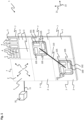
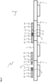
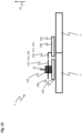
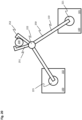
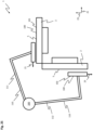
- Fig.1 shows a planar drive system 1 which has six stator modules 2.
- the stator modules 2 are arranged in such a way that a rectangle of two by three stator modules 2 is formed. Other arrangements of the stator modules 2 are also conceivable; more or fewer than six stator modules 2 can also be arranged.
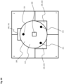
- the stator module 2 shown at the top right an interior of the stator module 2 is sketched, wherein the stator module 2 comprises four stator units 3, wherein the four stator units 3 are arranged within a stator module 2 in a square 2-by-2 arrangement.
- the stator units 3 comprise coil groups 4, wherein the coil groups 4 are shown with different orientations. The coil groups 4 serve to generate a stator magnetic field.
- the coil groups 4 are designed as rectangular and elongated coil groups 4, but can also be designed differently.
- each stator unit 3 of the stator modules 2 three individual, rectangular and elongated coils are shown in a coil group 4.
- a different number of individual rectangular and elongated coils could be used. form a coil group 4.
- a longitudinal extension of the coils is oriented parallel to one of the edges of the respective stator unit 3.
- This grid of elongated and rectangular coil groups 4 can be formed several times on top of each other. In reality neither stator units 3 nor coil groups 4 are visible, since they are surrounded by a stator module housing 7 of the stator module 2.
- the six stator modules 2 form a continuous stator surface 5 above the stator units 3.
- the stator surface 5 is delimited by the stator module housing 7.
- a control unit 10 is arranged, which is connected to one of the stator modules 2 by a data line 11.
- a communication connection (not shown) can also be formed between the stator modules 2.
- the control unit 10 is set up to output control signals via the data line 11 to the stator modules 2 or the stator units 3 within the stator modules 2 and the stator units 3 are set up to energize the coil groups 4 based on the control signals. Even if no stator units 3 or coil groups 4 are shown in the other stator modules 2, each stator module 2 is equipped with stator units 3 and coil groups 4. By supplying current, the coil groups 4 can provide a stator magnetic field, whereby the stator magnetic field can be used to move rotors 100 above the stator surface 5.
- Fig.1 Two runners 100 are shown, a first runner 101 and a second runner 102. Both in the first runner 101 and in the second runner 102, magnet units 105 are indicated, which in the Fig.1 selected isometric view, but which are arranged within the first rotor 101 and the second rotor 102.
- the magnet units 105 generate a rotor magnetic field.
- the rotor magnetic field can interact with the stator magnetic field generated by the coil groups 4 and thus drive the rotor 100 accordingly.
- the rotors 100 can be moved at least in a first direction 21 and in a second direction 22.
- the first direction 21 and the second direction 22 are perpendicular to one another and are arranged in a plane defined by the stator surface 5.
- the rotors 100 can also be moved perpendicular to the first direction 21 and the second direction 22.
- the rotors 100 can be moved at any Positions above the stator surface 5 can be rotated by a few degrees and tilted by a few degrees from a rest position parallel to the stator surface 5.
- the first rotor 101 and the second rotor 102 are connected to one another by means of a coupling device 110.
- the coupling device 110 is therefore arranged between the first rotor 101 and the second rotor 102.
- a connection between the first rotor 101 and the second rotor 102 can be formed by means of the coupling device 110.
- the control unit 10 outputs the control signals to the stator units 3 or the stator modules 2 in such a way that the coil groups 4 are energized based on the control signals in such a way that coordinated movements of the first rotor 101 and the second rotor 102 are carried out with respect to the coupling device 110 by means of the stator magnetic field. Since the first rotor 101 and the second rotor 102 are connected by the coupling device 110, it is necessary to coordinate the movements of the first rotor 101 and the second rotor 102 during operation of the planar drive system 1 and thus provide an overall improved planar drive system 1 with rotors 100 connected by means of the coupling device 110.
- stator modules 2 can have magnetic field sensors 6, by means of which a magnetic field can be determined.
- the magnetic field sensors 6 are in particular set up to determine the rotor magnetic fields of the magnet units 105 and to output corresponding measurement signals to the control unit 10. Using these measurement signals, a position of the rotors 100 can be determined by the control unit 10.
- connection between the first rotor 101 and the second rotor 102 provided by the coupling device 110 can be released during operation.
- the stator units 3 or the stator modules 2 are designed to energize the coil groups 4 using the control signals in such a way that the connection between the first rotor 101 and the second rotor 102 can be released and formed again.
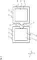
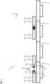
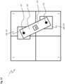
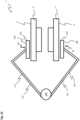
- Fig. 2 shows a plan view of a first runner 101 and a second runner 102, in which the coupling device 110 is designed such that the first runner 101 and the second runner 102 can be moved so that the connection between the first runner 101 and the second runner 102 can be formed and released again.
- the first runner 101 comprises a first coupling element 111, which is part of the coupling device 110.
- the second runner 102 comprises a second coupling element 112, which is also part of the coupling device 110.
- a positive connection and/or a mechanically force-fit connection can now be formed between the first coupling element 111 and the second coupling element 112.
- the first coupling element 111 has a recess 121 for this purpose.
- the second coupling element 112 has a projection 122 that fits the recess 121.
- the connection between the first rotor 101 and the second rotor 102 is formed by inserting the projection 122 into the recess 121. Furthermore, more than one recess 121 and more than one projection 122 can also be provided.
- both the recess 121 and the projection 122 are semicircular. It can be provided that the second rotor 102 is moved in the second direction 22 towards the first rotor 101 and as a result the projection 122 is inserted into the recess 121. Now the connection between the first rotor 101 and the second rotor 102 is stable at least in the first direction 21 due to a positive connection and a movement of the first rotor 101 in the first direction 21 automatically leads to a movement of the second rotor 102 in the first direction 21, provided that no opposing drive magnetic field is formed below the second rotor 102. In particular, the drive magnetic fields can be formed such that the first rotor 101 and the second rotor 102 move together.
- the Fig.1 Control unit 10 shown can be used for the Fig. 2 shown rotor 100 can be operated in a first operating mode and in a second operating mode.
- the control signals can be output based on coupling information in such a way that the connection of the first rotor 101 and the second rotor 102 is taken into account.
- the control signals are output based on decoupling information in such a way that the first rotor 101 and the second rotor 102 are moved individually.
- the control unit 10 therefore assumes that the first rotor 101 and the second rotor 102 are coupled and outputs the control signals for energizing the coil groups 4 accordingly.
- Information about the first operating mode and the second operating mode is provided by means of one of the stator modules 2 in Fig.1 shown magnetic field sensors 6, wherein the magnetic field sensors 6 detect the magnetic fields of the magnet units 105 and can thus determine the position of the first rotor 101 or the second rotor 102. If all stator modules 2 have such magnetic field sensors 6 and a dimension of the coupling device 110 is known, conclusions can be drawn about a coupling or decoupling from the position data of the rotors 100. Furthermore, information about whether a coupling or decoupling of the first rotor 101 and the second rotor 102 is present can be stored in a memory arranged on the first rotor 101 or second rotor 102 and transmitted to the control unit 10 by means of wireless data communication.
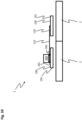
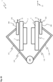
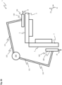
- Fig.3 shows another two runners 100 with a coupling device 110, which, like the coupling device of the Fig. 2 unless differences are described below.
- the recess 121 and the projection 122 have Fig.3 a different shape and are arranged obliquely in particular to the first direction 21 and the second direction 22. This results in a mechanical connection in the coupled state, i.e.
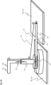
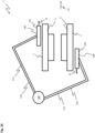
- Fig.4 shows a side view of a planar drive system 1 with two first runners 101 and two second runners 102.
- a first rotor 101 and a second rotor 102 are shown in the uncoupled state or in the state shortly before coupling.
- the coupling device 110 again comprises a first coupling element 111 of the first rotor 101 and a second coupling element 112 of the second rotor 102.
- the first coupling element 111 again comprises a recess 121
- the second coupling element 112 comprises a projection 122.
- the recess 121 and the projection 122 are arranged in such a way that insertion of the projection 122 into the recess 121 is not possible when the first rotor 101 and the second rotor 102 are parallel to the stator surface 5. However, if the first rotor 101 and/or the second rotor 102 are tilted from a position parallel to the stator surface 5, the first rotor 101 and the second rotor 102 can then be moved towards each other in such a way that the projection 122 is arranged below the recess 121 and a displacement of the first rotor 101 and/or the second rotor 102 into a rest position parallel to the stator surface 5 leads to an insertion of the projection 122 into the recess 121. This state is for the two in the illustration of the Fig.4 runner 100 shown on the right.
- the coupling mechanism of the Fig.4 Both the first runner 101 and the second runner 102 are tilted from the rest position. However, it can also be provided that only the first runner 101 or only the second runner 102 is tilted from the rest position to form or release the connection. If the connection is, as for the two runners 100 on the right in the illustration of the Fig.4 , by means of the coupling device 110, the first rotor 101 and the second rotor 102 can be moved together parallel to the stator surface 5 without the movement of one of the two rotors 100 causing the connection to be released again. Furthermore, drive forces for the first rotor 101 and the second rotor 102 can be combined.
- the recess 121 and the projection 122 in Fig.4 are shown with a triangular cross-section. However, other cross-sections for the recess 121 and the projection 122 are also conceivable.
- the first rotor 101 and the second rotor 102 in the planar drive system 1 of the Fig.4 are tilted in opposite directions to one another. This means that in the area of the coupling device 110, i.e.
- the first rotor 101 is moved away from the stator surface 5 in a third direction 23 perpendicular to the stator surface 5 and the second rotor 102 in the area of the second coupling element 112 is moved towards the stator surface 5 in the third direction 23.
- Fig.5 shows a top view of two further runners 100, which are connected to the runners 100 of the Figures 2 to 3 correspond, unless differences are described below.
- the first coupling element 111 in this case has both a recess 121 and a projection 122.
- the second coupling element 112 also has a recess 121 and a projection 122.
- the recess 121 of the first coupling element 111 matches the projection 122 of the second coupling element 112.
- the recess 121 of the second coupling element 112 matches the projection 122 of the first coupling element 111.
- Both the recesses 121 and the projections 122 are dovetail-shaped in this case, so that a mechanism analogous to the
- Fig.4 can be selected to connect the first runner 101 and the second runner 102 to each other by tilting the runners 100 in opposite directions to each other and then moving them towards each other and then bringing them back into the horizontal position so that the recesses 121 receive the projections 122.
- it can also be provided in the embodiments of the Figures 4 and 5 to move the first runner 101 and the second runner 102 in different planes with respect to the third direction 23 before forming the connection.
- the coupling devices 110 explained above can be part of an edge region surrounding the rotors 100.
- FIG. 2 to 5 only one connection option to a further rotor 100 was shown in each case, but it can also be provided that recesses 121 or projections 122 are arranged all the way around the rotors 100 in order to mechanically connect further rotors after the connection between the first rotor 101 and the second rotor 102 has been formed.
- a connection between the first rotor 101 and the second rotor 102 can also be released and then the first rotor 101 or the second rotor 102 can be connected to a further rotor.
- the connections can be made both in the first direction 21 and in the second direction 22.
- the mechanically connected rotors 100 can in particular provide a planar drive system 1 with an increased load-bearing capacity, since the load-bearing capacity of magnet units 105 of several rotors 100 can be used overall.
- first coupling element 111 is optionally integrated into a first circumferential edge element 123 of the first rotor 101 and the second coupling element 112 is optionally integrated into a second circumferential edge element 124 of the second rotor 102.
- Fig.6 shows a side view of a planar drive system 1, in which a first rotor 101 can also be connected to a second rotor 102.
- the first runner 101 and the second runner 102 are separated from each other.
- the coupling device 110 again has a first coupling element 111 of the first runner 101 and a second coupling element 112 of the second runner 102, wherein the first coupling element 111 again has a recess 121 and the second coupling element 112 again has a projection 122.
- the recess 121 is a dowel pin hole and the projection 122 is a dowel pin.
- the projection 122 can again be inserted parallel into the recess 121 and then leads to the right area of the Fig.6 shown connection between the first runner 101 and the second runner 102. As a result, the first runner 101 and the second runner 102 are connected to one another, in particular in the third direction 23.
- Fig.7 shows a side view of a planar drive system 1, in which the first coupling element 111 and the second coupling element 112 have a matching comb structure 127, wherein the comb structure 127 can also be formed by dowel pins or flat plates.
- the first rotor 101 and the second rotor 102 in the third direction 23 can be made.
- first coupling element 111 and the second coupling element 112 are not part of a respective peripheral edge element of the respective rotor 100.
- this can also be the case for the two rotors 100 of the embodiments of the Figures 4 , 6 and 7 be provided for, for example, in the Figures 2 , 3 and 5 shown.
- Fig.8 shows a top view of a planar drive system 1 in which a first rotor 101 and a second rotor 102 are connected to one another.
- the first coupling element 111 and the second coupling element 112 in this case comprise magnets 130.
- the first coupling element 111 of the first rotor 101 comprises four magnets 130, just like the second coupling element 112 of the second rotor 102.
- the magnets 130 each have a north pole 131 and a south pole 132.
- the magnets 130 are arranged on the rotors 100 in such a way that the north poles 131 and south poles 132 of the coupling device 110 also adjoin one another when the rotors 100 are adjacent to one another, and thus a magnetic force and thus a magnetically force-locking connection can be formed between the first rotor 101 and the second rotor 102.
- the magnets 130 are only arranged in such a way that a connection is formed in the second direction 22.
- the rotors 100 each have two magnets 130 in the edge regions facing the other rotor 100.
- magnets not shown and pointing in the first direction 21 can also be provided in addition or as an alternative.
- the magnets 130 can also be designed to be switchable, for example as electromagnets.
- the magnets 130 can comprise a permanent magnet and an electromagnet, wherein a magnetic field of the permanent magnet can be canceled by means of the electromagnet and the magnet 130 can thus be "switched off".
- the magnets 130 of the first coupling element 111 and/or the second coupling element 112 are rotatably mounted. If the magnets 130 are rotatably mounted, a system can be provided in which, by moving the first rotor 101 and the second rotor 102 relative to one another, the magnets 130 of the first rotor 101 come into the sphere of influence of the magnets 130 of the second rotor 102 and, due to the rotatability, align themselves in a scanning manner in such a way that a magnetically force-fit connection is provided between the first rotor 101 and the second rotor 102. Such a system is particularly flexible in use.
- the magnets 130 can also be integrated again into the first edge element 123 or the second edge element 124 of the rotor 100.
- the magnets 130 of the embodiment of the Fig.8 In addition to the mechanical connection options of the rotor 100 of the Figures 2 to 7 If both mechanical and magnetic connections are provided, a particularly stable arrangement of the first rotor 101 and the second rotor 102 can be provided.
- Fig.9 shows a side view of a planar drive system 1, in which a connection between a first runner 101 and a second runner 102 is also provided by means of a coupling device 110.
- the coupling device 110 is designed as a push rod 114 and is set up to move an element 200, which is located on the second runner 102, on the second runner 102 by a movement of the first runner 101, the push rod 114 being connected to the first runner 101.
- the movement of the element 200 can include a transfer above the second runner 102 or also a sliding down from the second runner 102.
- the element 200 can, for example, be a product transported by means of the planar drive system 1.
- Fig.10 shows a side view of a planar drive system 1, in which the coupling device 110 is designed as a lifting device 116.
- the element 200 arranged on the second runner 102, which is arranged on element projections 201, can be lifted by the lifting device 116, which is connected to the first runner 101.
- the lifting device 116 is moved under the element 200 and then the first runner 101 is raised and/or the second runner 102 is lowered.
- the moment the lifting device 116 touches the element 200 a connection is formed between the first runner 101 and the second runner 102 and the first runner 101 and the second runner 102 are moved in a coordinated manner relative to one another.
- the element 200 can again be a transported product.
- Fig. 11 shows a top view of a planar drive system 1, in which a coupling device 110 is again designed as a push rod 114 and is connected to a first runner 101.
- An element 200 which in turn can be a product, is arranged on a second runner 102, the element 200 being arranged on a turntable 210.
- the push rod 114 allows the element 200 to be rotated on the second runner 102 by means of the turntable 210.
- the moment the push rod 114 touches the element 200 the connection between the first runner 101 and the second runner 102 is again established and a coordinated movement of the first runner 101 and the second runner 102 takes place relative to one another.
- the turntable 210 has a projection (not shown) to which the push rod 114 can be attached. This allows the element 200 to be rotated without being touched by the push rod 114.
- Fig. 12 shows a top view of a planar drive system 1, in which a first runner 101 is also connected to a second runner 102 and the first runner 101 and the second runner 102 are moved in a coordinated manner.
- An element 200 which in turn can be a product moved by the planar drive system 1, is arranged on a third runner 103.
- the first runner 101 and the second runner 102 each have a clamping rod 118 with which the element 200 can be clamped.
- the third runner 103 can be moved away and the element 200 can then be held by the first runner 101 and the second runner 102 and, for example, transferred to another processing station or to another runner (not shown in each case).
- FIG. 12 several such systems consisting of first runner 101, second runner 102 and third runner 103 are shown, which are in the form of the clamping rod 118. In the upper illustration, the clamping rod 118 is straight, while in the lower illustration it is angled.
- Fig. 13 shows a top view of a planar drive system 1, in which the first coupling element 111 of the coupling device 110 of the first rotor 101 is designed as a rack 141.
- the second coupling element 112 of the coupling device 110 of the second rotor 102 is designed as a gear disk 142.
- An element 200 is arranged on the gear disk 142. If the first rotor 101 is moved in a coordinated manner along the second rotor 102 such that the rack 141 engages the gear disk 142, the rotatably mounted gear disk 142 on the second rotor 102 can be rotated by means of this movement and thus the element 200 can also be rotated. This also requires a coordinated movement of the first runner 101 and the second runner 102.
- the first runner 101 and the second runner 102 are in turn connected by means of the coupling device 110. Furthermore, by means of a rotation of the second runner 102 with the gear disk 142, a linear movement of an element on the first runner 101 can also be generated, which is transmitted to the rack 141.
- first runner 101 and the second runner 102 are in turn connected by means of the coupling device 110.
- Fig. 14 shows a planar drive system 1 in which the coupling device 110 is designed as a coupling 145.
- the first rotor 101 and the second rotor 102 are connected to one another by means of the coupling 145.
- the coupling 145 is designed to be fixed or detachable.
- Fig. 15 shows a side view of a planar drive system 1, in which the coupling device 110 again comprises a first coupling element 111 with a rack 141 and a second coupling element 112 with a gear disk 142.
- the gear disk 142 has an internal thread, by means of which a threaded rod 143 can be moved up or down, i.e. in the third direction 23.
- This can be used, for example, when the second rotor 102 is placed on the stator modules 2 in order to then generate large lifting forces by means of the threaded rod 143, for example for stamping, pressing or clamping.
- a connection between the first rotor 101 and the second rotor 102 can be made by connecting the rack 141 with the gear disk 142.
- the first runner 101 with the rack 141 can also be guided several times to the gear disk 142 and thus increase a stroke of the threaded rod 143.
- Fig. 16 shows a top view of the planar drive system 1 of the Fig. 15 . If the first runner 101 is moved in the first direction 21, the movement on the threaded rod 143 is converted into a movement in the third direction 23 via the rack 141 and the gear disk 142.
- Fig. 17 shows a plan view of a planar drive system 1, in which the coupling device 110 between the first rotor 101 and the second rotor 102 is designed as a plate 220, which is rectangular in shape here.
- the plate 220 is connected to the first rotor 101 and the second rotor 102 by means of rotary bearings 221.
- An element 200 arranged on the plate 220 can be brought into any desired rotational position by a movement of the first rotor 101 and the second rotor 102 relative to one another.
- Fig. 18 shows a planar drive system 1 which corresponds to the planar drive system 1 of the Fig. 17 , unless differences are described below.
- the plate 220 is round in this case and is also connected to a third rotor 103 via a pivot bearing 221. This also enables the rotation of the element 200 at any angle of rotation.
- More than two or three runners 100 can also be provided. The greater the number of runners 100 used, the heavier the element 200 can be.
- the element 200 on the plate 220 of the planar drive systems 1 of the Fig. 17 and 18 can in turn be a product moved with the planar drive system 1.
- Fig. 19 shows an isometric view of a first runner 101 and a second runner 102.
- a rotatably mounted crane 230 is arranged on the second runner 102.
- a coupling device 110 is arranged between the first runner 101 and the second runner 102.
- the coupling device 110 has a connecting rod 151, which is arranged with a slot 152 on the rotatably mounted crane 230.
- the slot 152 By means of the slot 152, the first runner 101 can be moved towards or away from the second runner 102 without a rotational movement of the rotatably mounted Crane 230. This can be done without the second runner 102 moving.
- the coupling device 110 further comprises a cable connection 155, wherein the pivotally mounted crane 230 is lowered by a movement of the first runner 101 away from the second runner 102 by means of the cable connection 155 and the pivotally mounted crane 230 is raised by a movement of the first runner 101 towards the second runner 102.
- a spring 233 is also arranged, with which an upper element 232 is pushed out of a lower element 231, wherein the lower element 231 is connected to the second runner 102.
- the upper element 232 can be lowered accordingly by the force transmitted via the cable connection 155 against the spring 233.
- a cord and/or a wire can also be used.
- the pivotally mounted crane 230 can be rotated accordingly around the second runner 102 by means of a coordinated movement of the first runner 101 relative to the second runner 102.
- both the height of the crane by means of the cable connection 155 and a rotational orientation of the crane 230 by means of the relative movement of the first runner 101 can be adjusted.
- Fig. 20 shows a plan view of two runners 100, which are also connected to a coupling device 110.
- the coupling device 110 comprises a scissor element 250 with a first gripper 251 and a second gripper 252.
- the first gripper 251 and the second gripper 252 are connected to one another by means of a rotary element 222.
- the first gripper 251 is also connected to the first runner 101 via a rotary bearing 221 and the second gripper 252 is connected to the second runner 102 via a rotary bearing 221.
- the first gripper 251 and the second gripper 252 can now be opened and closed, which can be used to hold an element 200.
- Fig. 21 shows a side view of a planar drive system 1, in this case the runners 100 are arranged below the stator modules 2. This is basically possible because the stator magnetic fields can also provide a corresponding holding force for the magnetic fields of the magnet units 105.
- a first runner 101 is connected to a second runner 102 via a coupling device 110.
- the coupling device 110 is also connected to a third runner 103.
- the coupling device 110 also has a gripper 260, which is connected to the first runner 101, the second runner 102 and the third runner 103 by a gripper rod 261.
- a position of the gripper 260 and an opening angle of the gripper 260 can also be controlled.
- One, several or all gripper rods 261 can also be replaced by ropes.
- Fig. 22 shows a side view of a planar drive system 1, in which two stator modules 2 are arranged opposite one another in such a way that the first rotor 101 is arranged on a first side of the arrangement of the two stator modules 2 and a second rotor 102 is arranged on a second side of the arrangement of the two stator modules 2.
- the stator surfaces 5 of the two stator modules 2 are parallel to one another.
- the coupling device 110 between the first rotor 101 and the second rotor 102 is in this case guided around the stator modules 2 and again has a first coupling element 111 and a second coupling element 112, which are connected via a held element 200.
- a position of the element 200 can be adjusted accordingly or the element 200 can also be released.
- a force 50 can be exerted on the rotors 100, with which the first coupling element 111 and the second coupling element 112 act on the element 200 and thus hold the element 200 in place. If the rotors 100 are moved against the direction in Fig. 22 represented force 50, the element 200 can be released.
- Fig. 23 shows the planar drive system 1 of the Fig. 22 after the first runner 101 and the second runner 102 have moved in the first direction 21.
- Fig. 24 shows the planar drive system 1 of the Fig. 22 after the first runner 101 has moved in the first direction 21 and the second runner 102 has moved in the opposite direction to the first direction 21.
- the second runner 102 has therefore moved antiparallel to the first runner 101.
- the element 200 can be lifted in the direction of the first runner 101.
- Fig. 25 shows a side view of a planar drive system 1, which is similar to the planar drive system 1 of Figures 22 to 24 is constructed.
- the stator modules 2 are not arranged opposite each other, but rather such that their stator surfaces 5 are at a 90-degree angle to each other. Otherwise, the position of the element 200 can be changed by moving the first rotor 101 or the second rotor 102 parallel to the respective stator surface 5. Furthermore, other angles of the stator surfaces 5 to each other are also possible.
- Fig. 26 shows the planar drive system 1 of the Fig. 25 after the first runner 101 and the second runner 102 have been moved accordingly.
- Fig. 27 shows a side view of a planar drive system 1, in which a first rotor 101 and a second rotor 102 are connected to one another by means of a coupling device 110 and in which the first rotor 101 and the second rotor 102 can be moved in a coordinated manner.
- the first rotor 101 and the second rotor 102 are each arranged above a stator module 2, with a gap being arranged between these stator modules 2, i.e. the stator modules 2 are arranged at a distance from one another.
- a holding element 119 connected to the coupling device 110 holds an element 200, which can again be a product transported by the planar drive system 1.
- the element 200 is accessible through the gap between the stator modules 2, for example for a processing step or for a visual inspection, for example by means of a camera.
Landscapes
- Engineering & Computer Science (AREA)
- Power Engineering (AREA)
- Physics & Mathematics (AREA)
- Chemical & Material Sciences (AREA)
- Combustion & Propulsion (AREA)
- Electromagnetism (AREA)
- Microelectronics & Electronic Packaging (AREA)
- Linear Motors (AREA)
Description
- Die Erfindung betrifft ein Planarantriebssystem und ein Verfahren zum Betreiben eines Planarantriebssystems.
- Diese Patentanmeldung beansprucht die Priorität der deutschen Patentanmeldung
DE 10 2021 121 530.7 , - Planarantriebssysteme können unter anderem in der Automatisierungstechnik, insbesondere der Fertigungstechnik, der Handhabungstechnik und der Verfahrenstechnik eingesetzt werden. Mittels Planarantriebssystemen kann ein bewegliches Element einer Anlage oder Maschine in mindestens zwei linear unabhängigen Richtungen bewegt oder positioniert werden. Planarantriebssysteme können einen permanent erregten elektromagnetischen Planarmotor mit einem planaren Stator und einen auf dem Stator in mindestens zwei Richtungen beweglichen Läufer umfassen. Dabei kann der planare Stator in beliebigen Einbaulagen eingebaut sein und beispielsweise der Läufer oberhalb des Stators, auf eine Normalrichtung zum Erdmittelpunkt hin bezogen, angeordnet sein. Das bedeutet, dass der Läufer beim Ausschalten des Planarantriebssystems auf dem Stator abgesetzt werden kann und so auf dem Stator gehalten werden kann. Es sind jedoch auch andere Einbaulagen denkbar, bei denen der Läufer mittels durch den Stator erzeugten Magnetkräften am Stator gehalten wird, und dabei eine Gewichtskraft des Läufers durch eine Magnetkraft ausgeglichen wird. Ein solches Planarantriebsystem ist aus
WO 2018176137 A1 bekannt. - Bei einem permanent erregten elektromagnetischen Planarmotor wird dadurch eine Antriebskraft auf den Läufer ausgeübt, dass bestromte Spulengruppen einer Statoreinheit mit Antriebsmagneten mehrerer Magnetanordnungen des Läufers magnetisch wechselwirken. Aus dem Stand der Technik sind Planarantriebssysteme mit rechteckigen und längsgestreckten Spulengruppen und rechteckigen und längsgestreckten Magnetanordnungen des Läufers bekannt. Ein solches Planarantriebssystem wird beispielsweise in der Offenlegungsschrift
DE 10 2017 131 304 A1 beschrieben. Mit einem solchen Planarantriebssystem wird insbesondere eine lineare und translative Bewegung des Läufers möglich. Das bedeutet, dass mittels eines solchen Planarantriebssystems der Läufer oberhalb einer Statorfläche, unter der die rechteckigen und längsgestreckten Spulengruppen angeordnet sind, parallel zur Statorfläche frei beweglich und senkrecht zur Statorfläche zumindest in verschiedenen Abständen zur Statorfläche bewegt werden kann. Ferner ist ein solches Planarantriebssystem in der Lage, den Läufer um einige Grad zu kippen und um einige Grad zu rotieren. Die letztgenannten Bewegungen sind dabei oberhalb von beliebigen Punkten der Statorfläche durchführbar. Dadurch, dass der Läufer um einige Grad gekippt oder rotiert werden kann, steht ein Planarantriebssystem mit für die meisten Anwendungen ausreichenden Freiheitsgraden zur Verfügung. Es kann jedoch sein, dass der Einsatzzweck des Planarantriebssystems weitere Bewegungen erfordert, die mittels eines Läufers des Planarantriebssystems so nicht ausgeführt werden können. - Es ist eine Aufgabe der Erfindung, ein Planarantriebssystem bereitzustellen, mit dem grö-βere Freiheitsgrade der Bewegung von auf Läufern angeordneten Objekten ermöglicht werden. Es ist eine weitere Aufgabe der Erfindung, ein entsprechendes Betriebsverfahren für ein solches Planarantriebssystem anzugeben.
- Diese Aufgaben werden mit dem Planarantriebssystem und dem Verfahren zum Betreiben eines Planarantriebssystems der unabhängigen Patentansprüche gelöst. Vorteilhafte Weiterbildungen sind jeweils in abhängigen Patentansprüchen angegeben.
- Ein Planarantriebssystem weist zumindest eine Statoreinheit mit jeweils einer Mehrzahl von Spulengruppen zum Erzeugen eines Statormagnetfelds, eine Statorfläche oberhalb der Statoreinheit sowie einen ersten Läufer und einen zweiten Läufer auf. Der erste Läufer und der zweite Läufer weisen jeweils eine Mehrzahl von Magneteinheiten zum Erzeugen eines Läufermagnetfelds auf. Der erste Läufer und der zweite Läufer sind oberhalb der Statorfläche mittels einer Wechselwirkung des Statormagnetfelds mit dem Läufermagnetfeld zumindest in einer ersten Richtung und einer zweiten Richtung bewegbar. Dabei kann vorgesehen sein, dass eine oder mehrere Statoreinheiten in einem Statormodul angeordnet sind und die Statorfläche eine zusammenhängende Fläche der Statormodule bzw. der Statoreinheiten bildet. Die Statorfläche kann dabei insbesondere im Wesentlichen zweidimensional in der ersten Richtung und der zweiten Richtung ausgestaltet sein, sodass der erste Läufer und der zweite Läufer im Wesentlichen parallel zur Statorfläche bewegt werden können. Ferner ist im erfindungsgemäßen Planarantriebssystem eine Koppelvorrichtung zwischen dem ersten Läufer und dem zweiten Läufer angeordnet, mit der eine Verbindung zwischen dem ersten Läufer und dem zweiten Läufer ausbildbar ist. Das Planarantriebssystem weist ferner eine Steuereinheit auf, wobei die Steuereinheit eingerichtet ist, Steuersignale an die Statoreinheit auszugeben. Die Steuereinheit kann ferner eingerichtet sein, Signale von in den Statormodulen angeordneten Magnetfeldsensoren zu empfangen und diese Signale für eine Positionsbestimmung des ersten Läufers beziehungsweise zweiten Läufers zu nutzen. Sind mehrere Statoreinheiten vorhanden, können die Steuersignale an mehrere Statoreinheiten ausgegeben werden. Sind eine oder mehrere Statoreinheiten in einem Statormodul angeordnet, kann vorgesehen sein, dass die Ausgabe der Steuerbefehle an die Statoreinheiten als eine Ausgabe von Steuerbefehlen an die Statormodule ausgestaltet ist. Die Statoreinheit ist eingerichtet, die Spulengruppen anhand der Steuersignale derart zu bestromen, dass mittels des Statormagnetfelds zueinander hinsichtlich der Koppelvorrichtung koordinierte Bewegungen des ersten Läufers und des zweiten Läufers ausgeführt werden.
- Durch die koordiniert ausgeführte Bewegung ist es möglich, ein auf dem ersten Läufer und/oder ein auf dem zweiten Läufer angeordnetes Objekt gegebenenfalls in Freiheitsgraden zu bewegen, die mit dem ersten Läufer oder dem zweiten Läufer jeweils für sich alleine so nicht möglich wären. Die koordinierte Bewegung kann ferner dann, wenn die Verbindung zwischen dem ersten Läufer und dem zweiten Läufer ausgebildet ist, umfassen, die Spulengruppen derart zu bestromen, dass ein Gesamtsystem bestehend aus dem ersten Läufer und dem zweiten Läufer bewegt wird, ohne individuell unterschiedliche Bewegungen des ersten Läufers und des zweiten Läufers durchzuführen.
- Die Statormodule können ein Statormodulgehäuse umfassen, wobei die Statoreinheiten der Statormodule jeweils innerhalb der Statormodulgehäuse angeordnet sind.
- In einer Ausführungsform ist die Verbindung im Betrieb lösbar und die Statoreinheit eingerichtet, die Spulengruppen anhand der Steuersignale derart zu bestromen, dass die Verbindung gelöst werden kann und wieder ausgebildet werden kann. In dieser Ausführungsform ist das Planarantriebssystem eingerichtet, den ersten Läufer und den zweiten Läufer mittels der Koppelvorrichtung miteinander zu verbinden und die dabei entstehende Verbindung im Betrieb ebenfalls wieder zu lösen. Dadurch können beispielsweise im Rahmen des Einsatzes des Planarantriebssystems in der Automatisierungstechnik Bewegungen eines Objekts auf beispielsweise dem ersten Läufer in Freiheitsgraden, die ohne eine Kopplung des ersten Läufers mit dem zweiten Läufer nicht möglich wären, bewegt werden.
- In einer Ausführungsform kann die Steuereinheit in einem ersten Betriebsmodus und in einem zweiten Betriebsmodus betrieben werden. Im ersten Betriebsmodus werden die Steuersignale anhand einer Koppelungsinformation derart ausgegeben, dass die bestehende Verbindung des ersten Läufers und des zweiten Läufers berücksichtigt wird. Im zweiten Betriebsmodus werden die Steuersignale anhand einer Entkoppelungsinformation derart ausgegeben, dass der erste Läufer und der zweite Läufer individuell bewegt werden. Im ersten Betriebsmodus ist also die Verbindung zwischen dem ersten Läufer und dem zweiten Läufer ausgebildet und die Steuersignale werden für eine gemeinsame, koordinierte Bewegung des ersten Läufers und des zweiten Läufers ausgegeben. Im zweiten Betriebsmodus ist die Verbindung zwischen dem ersten Läufer und dem zweiten Läufer gelöst und die Steuersignale werden derart ausgegeben, dass der erste Läufer und der zweite Läufer individuell und unabhängig voneinander bewegt werden können.
- In einer Ausführungsform weist der erste Läufer ein erstes Koppelelement und der zweite Läufer ein zweites Koppelelement auf. Das erste Koppelelement und das zweite Koppelelement sind Teil der Koppelvorrichtung. Zwischen dem ersten Koppelelement und dem zweiten Koppelelement kann eine formschlüssige Verbindung und/oder eine mechanisch kraftschlüssige Verbindung und/oder eine magnetisch kraftschlüssige Verbindung ausgebildet werden. Dabei kann vorgesehen sein, dass die formschlüssige Verbindung und/oder die mechanisch kraftschlüssige Verbindung und/oder die magnetisch kraftschlüssige Verbindung dadurch ausgebildet werden, dass der erste Läufer und der zweite Läufer auf eine vorgegebene Weise relativ zueinander bewegt werden, bis die entsprechende Verbindung ausgebildet ist. Zunächst wird die Steuereinheit dabei also im zweiten Betriebsmodus betrieben, bei dem der erste Läufer und der zweite Läufer individuell bewegt werden können. Nach Ausbilden der Verbindung kann dann in den ersten Betriebsmodus der Steuereinheit gewechselt werden und der erste Läufer und der zweite Läufer können gemeinsam koordiniert bewegt werden.
- In einer Ausführungsform stellen das erste Koppelelement und das zweite Koppelelement eine mechanische Kopplung zwischen dem ersten Läufer und dem zweiten Läufer bereit. In einer Ausführungsform stellen das erste Koppelelement und das zweite Koppelelement eine magnetische Kopplung zwischen dem ersten Läufer und dem zweiten Läufer bereit. Dabei kann beispielsweise auch vorgesehen sein, dass das erste Koppelelement und das zweite Koppelelement sowohl eine mechanische als auch eine magnetische Kopplung bereitstellen.
- In einer Ausführungsform umfasst das erste Koppelelement eine Ausnehmung und das zweite Koppelelement einen zur Ausnehmung passenden beziehungsweise komplementären Vorsprung. Die Verbindung wird dadurch ausgebildet, dass der Vorsprung in die Ausnehmung eingesetzt wird. Das Einsetzen des Vorsprungs in die Ausnehmung kann dabei durch eine koordinierte Bewegung des ersten Läufers und des zweiten Läufers relativ zueinander erfolgen.
- In einer Ausführungsform kann zum Lösen der Verbindung der erste Läufer und/oder der zweite Läufer aus einer durch die erste Richtung und die zweite Richtung definierten Ebene gekippt werden. Dadurch wird es beispielsweise möglich, dass mittels des Vorsprungs und der Ausnehmung eine formschlüssige Verbindung des ersten Läufers und des zweiten Läufers in der durch die erste Richtung und zweite Richtung definierten Ebene ermöglicht ist und eine Bewegung des ersten Läufers oder des zweiten Läufers in dieser Ebene aufgrund der formschlüssigen Verbindung zu einer Bewegung des jeweiligen anderen Läufers führt. Das Lösen der Verbindung kann dabei dadurch erfolgen, dass der erste Läufer und/oder der zweite Läufer entsprechend aus der Ebene heraus gekippt werden und dadurch der Vorsprung aus der Ausnehmung entfernt wird. Der erste Läufer und der zweite Läufer können dann voneinander wegbewegt und anschließend wieder in eine Normallage parallel zur Statorfläche gekippt werden, sodass der erste Läufer und der zweite Läufer dann wieder individuell und unabhängig voneinander bewegt werden können.
- In einer Ausführungsform können der erste Läufer und der zweite Läufer zum Lösen der Verbindung entgegengesetzt zueinander gekippt werden.
- In einer Ausführungsform ist das erste Koppelelement in ein erstes umlaufendes Randelement des ersten Läufers integriert und das zweite Koppelelement ist in ein zweites umlaufendes Randelement des zweiten Läufers integriert.
- In einer Ausführungsform umfassen das erste Koppelelement und das zweite Koppelelement Magnete. In einer Ausführungsform sind die Magnete des ersten Koppelelements und/oder die Magnete des zweiten Koppelelements drehbar gelagert. Sind die Magnete drehbar gelagert, kann dabei eine Koppelvorrichtung bereitgestellt werden, bei der die drehbar gelagerten Magnete sich, wenn der erste Läufer und der zweite Läufer zueinander bewegt werden, derart in eine Position drehen, dass zwischen den Magneten eine entsprechende magnetische Kraft zwischen dem ersten Läufer und dem zweiten Läufer ausgebildet wird, die zu einer Verbindung des ersten Läufers und des zweiten Läufers führt. Alternativ können die Magnete auch auf vorgegebenen Positionen fest installiert sein, wobei in diesem Fall gegebenenfalls Einschränkungen hinsichtlich der Koppelbarkeit in Kauf genommen werden müssen.
- In einer Ausführungsform ist die Koppelvorrichtung eingerichtet, durch eine Bewegung des zweiten Läufers relativ zum ersten Läufer eine Bewegung eines auf dem ersten Läufer angeordneten Elements auszulösen. Der zweite Läufer kann also dazu genutzt werden, über die Koppelvorrichtung eine Bewegung mechanisch auf ein Element des ersten Läufers zu übertragen. Dies kann dabei sowohl mit lösbaren als auch mit nicht-lösbaren Verbindungen zwischen dem ersten Läufer und dem zweiten Läufer erfolgen.
- Ferner wird ein Verfahren zum Betreiben eines solchen Planarantriebssystems bereitgestellt, wobei das Planarantriebssystem die bereits genannten Eigenschaften aufweist. Die Steuereinheit gibt in diesem Planarantriebssystem Steuersignale an die Statoreinheit aus, und die Statoreinheit bestromt die Spulengruppen anhand der Steuersignale derart, dass mittels des Statormagnetfelds zueinander koordinierte Bewegungen des ersten Läufers und des zweiten Läufers ausgeführt werden.
- In einer Ausführungsform des Verfahrens wird die Verbindung im Betrieb gelöst, wobei die Statoreinheit die Spulengruppen anhand der Steuersignale derart bestromt, dass die Verbindung gelöst und wieder ausgebildet wird.
- In einer Ausführungsform des Verfahrens kann die Steuereinheit in einem ersten Betriebsmodus und in einem zweiten Betriebsmodus betrieben werden. Im ersten Betriebsmodus werden die Steuersignale anhand einer Kopplungsinformation derart ausgegeben, dass die Verbindung des ersten Läufers und des zweiten Läufers berücksichtigt wird. Im zweiten Betriebsmodus werden die Steuersignale anhand einer Entkoppelungsinformation derart ausgegeben, dass der erste Läufer und der zweite Läufer individuell bewegt werden.
- Die Erfindung wird anhand der beigefügten Figuren näher erläutert. Hierbei zeigen:
- Fig. 1
- ein Planarantriebssystem;
- Fig. 2
- zwei Läufer eines Planarantriebssystems mit einer mechanischen Koppelvorrichtung;
- Fig. 3
- zwei Läufer eines Planarantriebssystems mit einer weiteren mechanischen Koppelvorrichtung;
- Fig. 4
- eine Seitenansicht eines Planarantriebssystems mit Läufern mit mechanischen Koppelvorrichtungen;
- Fig. 5
- zwei Läufer eines Planarantriebssystems mit einer weiteren mechanischen Koppelvorrichtung;
- Fig. 6
- eine Seitenansicht eines Planarantriebssystems mit zwei Läufern mit einer weiteren mechanischen Koppelvorrichtung;
- Fig. 7
- eine Seitenansicht eines Planarantriebssystems mit Läufern mit einer weiteren mechanischen Koppelvorrichtung;
- Fig. 8
- eine Draufsicht auf ein Planarantriebssystem mit Läufern mit einer magnetischen Koppelvorrichtung;
- Fig. 9
- eine Seitenansicht eines Planarantriebssystems;
- Fig. 10
- eine Seitenansicht eines Planarantriebssystems;
- Fig. 11
- eine Draufsicht auf ein Planarantriebssystem;
- Fig. 12
- eine Draufsicht auf ein Planarantriebssystem;
- Fig. 13
- eine Draufsicht auf ein Planarantriebssystem;
- Fig. 14
- eine Draufsicht auf ein Planarantriebssystem;
- Fig. 15
- eine Seitenansicht eines Planarantriebssystems;
- Fig. 16
- eine Draufsicht auf ein Planarantriebssystem;
- Fig. 17
- eine Draufsicht auf ein Planarantriebssystem;
- Fig. 18
- eine Draufsicht auf ein Planarantriebssystem;
- Fig. 19
- eine isometrische Ansicht zweier Läufer eines Planarantriebssystems;
- Fig. 20
- eine Draufsicht auf zwei Läufer eines Planarantriebssystems;
- Fig. 21
- eine Seitenansicht eines Planarantriebssystems;
- Fig. 22
- eine Seitenansicht eines Planarantriebssystems;
- Fig. 23
- eine Seitenansicht eines Planarantriebssystems;
- Fig. 24
- eine Seitenansicht eines Planarantriebssystems;
- Fig. 25
- eine Seitenansicht eines Planarantriebssystems;
- Fig. 26
- eine Seitenansicht eines Planarantriebssystems; und
- Fig. 27
- eine Seitenansicht eines Planarantriebssystems.
-
Fig. 1 zeigt ein Planarantriebssystem 1, welches sechs Statormodule 2 aufweist. Die Statormodule 2 sind derart angeordnet, dass ein Rechteck von zwei auf drei Statormodulen 2 gebildet ist. Auch andere Anordnungen der Statormodule 2 sind denkbar, es können auch mehr oder weniger als sechs Statormodule 2 angeordnet werden. Im oben rechts dargestellten Statormodul 2 ist ein Innenleben des Statormoduls 2 skizziert, wobei das Statormodul 2 vier Statoreinheiten 3 umfasst, wobei die vier Statoreinheiten 3 innerhalb eines Statormoduls 2 in einer quadratischen 2-auf-2-Anordnung angeordnet sind. Ferner ist für zwei Statoreinheiten 3 dargestellt, dass die Statoreinheiten 3 Spulengruppen 4 umfassen, wobei die Spulengruppen 4 mit unterschiedlicher Ausrichtung dargestellt sind. Die Spulengruppen 4 dienen zum Erzeugen eines Statormagnetfelds. Die Spulengruppen 4 sind in der dargestellten Ausführungsform als rechteckige und längsgestreckte Spulengruppen 4 ausgestaltet, können jedoch auch anders ausgestaltet sein. In jeder Statoreinheit 3 der Statormodule 2 sind jeweils drei einzelne, rechteckige und längsgestreckte Spulen in einer Spulengruppe 4 dargestellt. Ebenso könnte bei einer nicht dargestellten Ausführungsform eine andere Anzahl an einzelnen rechteckigen und längsgestreckten Spulen eine Spulengruppe 4 bilden. Dabei orientiert sich eine Längserstreckung der Spulen parallel zu einer der Kanten der jeweiligen Statoreinheit 3. Unterhalb jeder dargestellten Spulengruppen 4 sind weitere Spulen vorhanden, die in Bezug auf ihre Längserstreckung eine um 90 Grad gedrehte Orientierung aufweisen. Dieses Raster aus längsgestreckten und rechteckigen Spulengruppen 4 kann mehrfach übereinander ausgebildet sein. Real sind weder Statoreinheiten 3 noch Spulengruppen 4 sichtbar, da sie von einem Statormodulgehäuse 7 des Statormoduls 2 umgeben sind. - Die sechs Statormodule 2 bilden eine zusammenhängende Statorfläche 5 oberhalb der Statoreinheiten 3. Die Statorfläche 5 wird dabei durch die Statormodulgehäuse 7 begrenzt. Ferner ist eine Steuereinheit 10 angeordnet, die mit einer Datenleitung 11 mit einem der Statormodule 2 verbunden ist. Zwischen den Statormodulen 2 kann ebenfalls eine (nicht dargestellte) Kommunikationsverbindung ausgebildet sein. Die Steuereinheit 10 ist eingerichtet, Steuersignale über die Datenleitung 11 an die Statormodule 2 bzw. die Statoreinheiten 3 innerhalb der Statormodule 2 auszugeben und die Statoreinheiten 3 sind eingerichtet, die Spulengruppen 4 anhand der Steuersignale zu bestromen. Dabei ist, auch wenn in den anderen Statormodulen 2 keine Statoreinheiten 3 oder Spulengruppen 4 dargestellt sind, jedes Statormodul 2 mit Statoreinheiten 3 und Spulengruppen 4 ausgestattet. Durch die Bestromung können die Spulengruppen 4 ein Statormagnetfeld bereitstellen, wobei mittels des Statormagnetfelds Läufer 100 oberhalb der Statorfläche 5 bewegt werden können.
- In
Fig. 1 sind zwei Läufer 100 dargestellt, ein erster Läufer 101 sowie ein zweiter Läufer 102. Sowohl im ersten Läufer 101 als auch im zweiten Läufer 102 sind Magneteinheiten 105 angedeutet, die in der inFig. 1 gewählten isometrischen Ansicht nicht sichtbar sind, sondern die innerhalb des ersten Läufers 101 sowie des zweiten Läufers 102 angeordnet sind. Die Magneteinheiten 105 erzeugen ein Läufermagnetfeld. Zum Antrieb der Läufer 100 oberhalb der Statorfläche 5 kann das Läufermagnetfeld mit dem durch die Spulengruppen 4 erzeugten Statormagnetfeld wechselwirken und so den Läufer 100 entsprechend antreiben. Mittels der Wechselwirkung des durch die Spulengruppen 4 erzeugten Statormagnetfelds und des durch die Magneteinheiten 105 erzeugten Läufermagnetfelds können die Läufer 100 zumindest in einer ersten Richtung 21 und in einer zweiten Richtung 22 bewegt werden. Die erste Richtung 21 und die zweite Richtung 22 stehen dabei senkrecht aufeinander und sind in einer durch die Statorfläche 5 definierten Ebene angeordnet. In gewissem Maß können die Läufer 100 auch senkrecht zur ersten Richtung 21 und zur zweiten Richtung 22 bewegt werden. Ferner können die Läufer 100 an beliebigen Positionen oberhalb der Statorfläche 5 um einige Grad gedreht und um einige Grad aus einer Ruhelage parallel zur Statorfläche 5 verkippt werden. Der erste Läufer 101 und der zweite Läufer 102 sind mittels einer Koppelvorrichtung 110 miteinander verbunden. Die Koppelvorrichtung 110 ist also zwischen dem ersten Läufer 101 und dem zweiten Läufer 102 angeordnet. Mittels der Koppelvorrichtung 110 ist eine Verbindung zwischen dem ersten Läufer 101 und dem zweiten Läufer 102 ausbildbar. - Die Steuereinheit 10 gibt die Steuersignale an die Statoreinheiten 3 bzw. die Statormodule 2 derart aus, dass die Spulengruppen 4 anhand der Steuersignale derart bestromt werden, dass mittels des Statormagnetfelds zueinander hinsichtlich der Koppelvorrichtung 110 koordinierte Bewegungen des ersten Läufers 101 und des zweiten Läufers 102 ausgeführt werden. Da der erste Läufer 101 und der zweite Läufer 102 durch die Koppelvorrichtung 110 verbunden sind, ist es notwendig, im Betrieb des Planarantriebssystems 1 die Bewegungen des ersten Läufers 101 und des zweiten Läufers 102 zu koordinieren und so insgesamt ein verbessertes Planarantriebssystem 1 mit mittels der Koppelvorrichtung 110 verbundenen Läufern 100 bereitzustellen.
- Im oben links dargestellten Statormodul 2 ist skizziert, dass die Statormodule 2 Magnetfeldsensoren 6 aufweisen können, mittels denen ein Magnetfeld bestimmt werden kann. Die Magnetfeldsensoren 6 sind insbesondere eingerichtet, die Läufermagnetfelder der Magneteinheiten 105 zu ermitteln und entsprechende Messignale an die Steuereinheit 10 auszugeben. Mittels dieser Messsignale kann eine Position der Läufer 100 von der Steuereinheit 10 bestimmt werden.
- In einem Ausführungsbeispiel ist die durch die Koppelvorrichtung 110 bereitgestellte Verbindung des ersten Läufers 101 mit dem zweiten Läufer 102 im Betrieb lösbar. Die Statoreinheiten 3 bzw. die Statormodule 2 sind eingerichtet, die Spulengruppen 4 anhand der Steuersignale derart zu bestromen, dass die Verbindung zwischen dem ersten Läufer 101 und dem zweiten Läufer 102 gelöst werden kann und wieder ausgebildet werden kann.
-
Fig. 2 zeigt eine Draufsicht auf einen ersten Läufer 101 und einen zweiten Läufer 102, bei der die Koppelvorrichtung 110 derart ausgestaltet ist, dass der erste Läufer 101 und der zweite Läufer 102 so bewegt werden können, dass die Verbindung zwischen dem ersten Läufer 101 und dem zweiten Läufer 102 ausgebildet werden kann und wieder gelöst werden kann. Der erste Läufer 101 umfasst dabei ein erstes Koppelelement 111, welches Teil der Koppelvorrichtung 110 ist. Der zweite Läufer 102 umfasst ein zweites Koppelelement 112, welches ebenfalls Teil der Koppelvorrichtung 110 ist. Zwischen dem ersten Koppelelement 111 und dem zweiten Koppelelement 112 kann nun eine formschlüssige Verbindung und/oder eine mechanisch kraftschlüssige Verbindung ausgebildet werden. Das erste Koppelelement 111 weist hierzu eine Ausnehmung 121 auf. Das zweite Koppelelement 112 weist einen zur Ausnehmung 121 passenden Vorsprung 122 auf. Die Verbindung zwischen dem ersten Läufer 101 und dem zweiten Läufer 102 wird dadurch ausgebildet, dass der Vorsprung 122 in die Ausnehmung 121 eingesetzt wird. Ferner können auch mehr als eine Ausnehmung 121 und mehr als ein Vorsprung 122 vorgesehen sein. - Im Ausführungsbeispiel der
Fig. 2 sind sowohl die Ausnehmung 121 als auch der Vorsprung 122 halbkreisförmig. Dabei kann vorgesehen sein, dass der zweite Läufer 102 in der zweiten Richtung 22 auf den ersten Läufer 101 zubewegt wird und dadurch der Vorsprung 122 in die Ausnehmung 121 eingesetzt wird. Nun ist die Verbindung zwischen dem ersten Läufer 101 und dem zweiten Läufer 102 zumindest in der ersten Richtung 21 durch eine formschlüssige Verbindung stabil und eine Bewegung des ersten Läufers 101 in die erste Richtung 21 führt automatisch auch zu einer Bewegung des zweiten Läufers 102 in die erste Richtung 21, sofern unterhalb des zweiten Läufers 102 kein entgegengesetztes Antriebsmagnetfeld ausgebildet ist. Insbesondere können die Antriebsmagnetfelder derart ausgebildet werden, dass sich der erste Läufer 101 und der zweite Läufer 102 gemeinsam bewegen. - Die in
Fig. 1 gezeigte Steuereinheit 10 kann für die inFig. 2 gezeigten Läufer 100 in einem ersten Betriebsmodus und in einem zweiten Betriebsmodus betrieben werden. Im ersten Betriebsmodus können die Steuersignale anhand einer Kopplungsinformation derart ausgegeben werden, dass die Verbindung des ersten Läufers 101 und des zweiten Läufers 102 berücksichtigt wird. Im zweiten Betriebsmodus werden anhand einer Entkoppelungsinformation die Steuersignale derart ausgegeben, dass der erste Läufer 101 und der zweite Läufer 102 individuell bewegt werden. Die Steuereinheit 10 geht also im ersten Betriebsmodus davon aus, dass der erste Läufer 101 und der zweite Läufer 102 gekoppelt sind, und gibt die Steuersignale zur Bestromung der Spulengruppen 4 entsprechend aus. Eine Information über den ersten Betriebsmodus und den zweiten Betriebsmodus erfolgt dabei mittels in einem der Statormodule 2 inFig. 1 gezeigten Magnetfeldsensoren 6, wobei die Magnetfeldsensoren 6 die Magnetfelder der der Magneteinheiten 105 detektieren und so die Position des ersten Läufers 101 bzw. des zweiten Läufers 102 bestimmen können. Wenn alle Statormodule 2 solche Magnetfeldsensoren 6 aufweisen und eine Abmessung der Koppelvorrichtung 110 bekannt ist, können aus den Positionsdaten der Läufer 100 Rückschlüsse über eine Kopplung bzw. Entkoppelung getroffen werden. Ferner kann auch eine Information darüber, ob eine Kopplung bzw. Entkoppelung des ersten Läufers 101 und des zweiten Läufers 102 vorliegt, in einem auf dem ersten Läufer 101 oder zweiten Läufer 102 angeordneten Speicher abgelegt sein und mittels drahtloser Datenkommunikation an die Steuereinheit 10 übertragen werden. -
Fig. 3 zeigt weitere zwei Läufer 100 mit einer Koppelvorrichtung 110, die wie die Koppelvorrichtung derFig. 2 aufgebaut ist, sofern im Folgenden keine Unterschiede beschrieben sind. Die Ausnehmung 121 und der Vorsprung 122 weisen inFig. 3 eine andere Form auf und sind insbesondere zur ersten Richtung 21 und zur zweiten Richtung 22 jeweils schräg angeordnet. Somit ergibt sich in gekoppeltem Zustand, also wenn der Vorsprung 122 des zweiten Läufers 102 in die Ausnehmung 121 des ersten Läufers 101 eingesetzt wird, eine mechanische Verbindung, die sowohl in der ersten Richtung 21 als auch in der zweiten Richtung 22 zumindest teilweise formschlüssig und zumindest teilweise mechanisch kraftschlüssig ist, da einerseits eine Reibekraft zwischen der Ausnehmung 121 und dem Vorsprung 122 und auch die Form von Ausnehmung 121 und Vorsprung 122 zum Kraftübertrag vom ersten Läufer 101 auf den zweiten Läufer 102 genutzt werden können. Nur durch eine Bewegung parallel zum Vorsprung 122 kann die Verbindung zwischen erstem Läufer 101 und zweitem Läufer 102 wieder gelöst werden. -
Fig. 4 zeigt eine Seitenansicht eines Planarantriebssystems 1 mit zwei ersten Läufern 101 und zwei zweiten Läufern 102. Im linken Bereich der Darstellung derFig. 4 sind ein erster Läufer 101 und ein zweiter Läufer 102 in entkoppeltem Zustand bzw. im Zustand kurz vor der Kopplung dargestellt. Die Koppelvorrichtung 110 umfasst wieder ein erstes Koppelelement 111 des ersten Läufers 101 und ein zweites Koppelelement 112 des zweiten Läufers 102. Das erste Koppelelement 111 umfasst wieder eine Ausnehmung 121, das zweite Koppelelement 112 umfasst einen Vorsprung 122. Die Ausnehmung 121 und der Vorsprung 122 sind dabei derart angeordnet, dass ein Einsetzen des Vorsprungs 122 in die Ausnehmung 121 nicht möglich ist, wenn der erste Läufer 101 und der zweite Läufer 102 parallel zur Statorfläche 5 stehen. Werden jedoch der erste Läufer 101 und/oder der zweite Läufer 102 aus einer Lage parallel zur Statorfläche 5 verkippt, so können der erste Läufer 101 und der zweite Läufer 102 anschließend aufeinander zu bewegt werden derart, dass der Vorsprung 122 unterhalb der Ausnehmung 121 angeordnet ist und ein Verbringen des ersten Läufers 101 und/oder des zweiten Läufers 102 in eine Ruhelage parallel zur Statorfläche 5 zu einem Einsetzen des Vorsprungs 122 in die Ausnehmung 121 führt. Dieser Zustand ist für die beiden in der Darstellung derFig. 4 rechts dargestellten Läufer 100 zu sehen. - Beim Koppelmechanismus der
Fig. 4 werden sowohl der erste Läufer 101 als auch der zweite Läufer 102 aus der Ruhelage verkippt. Es kann jedoch auch vorgesehen sein, dass nur der erste Läufer 101 oder nur der zweite Läufer 102 zum Ausbilden oder Lösen der Verbindung aus der Ruhelage gekippt werden soll. Ist die Verbindung, wie für die beiden Läufer 100 rechts in der Darstellung derFig. 4 , mittels der Koppelvorrichtung 110 ausgebildet, so können der erste Läufer 101 und der zweite Läufer 102 parallel zur Statorfläche 5 gemeinsam bewegt werden, ohne dass die Bewegung eines der beiden Läufer 100 dazu führt, dass die Verbindung sich wieder löst. Ferner können Antriebskräfte für den ersten Läufer 101 und den zweiten Läufer 102 kombiniert werden. - Die Ausnehmung 121 und der Vorsprung 122 in
Fig. 4 sind mit dreieckigem Querschnitt dargestellt. Es sind jedoch auch andere Querschnitte für die Ausnehmung 121 und den Vorsprung 122 denkbar. Zum Ausbilden oder zum Lösen der Verbindung zwischen dem ersten Läufer 101 und dem zweiten Läufer 102 im Planarantriebssystem 1 derFig. 4 werden der erste Läufer 101 und der zweite Läufer 102 entgegengesetzt zueinander gekippt. Das bedeutet, dass im Bereich der Koppelvorrichtung 110, also insbesondere im Bereich des ersten Koppelelements 111 und des zweiten Koppelelements 112 der erste Läufer 101 bezogen auf eine dritte Richtung 23 senkrecht zur Statorfläche 5 von der Statorfläche 5 wegbewegt wird und der zweite Läufer 102 im Bereich des zweiten Koppelelements 112 bezogen auf die dritte Richtung 23 zur Statorfläche 5 hinbewegt wird. -
Fig. 5 zeigt eine Draufsicht auf zwei weitere Läufer 100, die den Läufern 100 derFiguren 2 bis 3 entsprechen, sofern im Folgenden keine Unterschiede beschrieben sind. Das erste Koppelelement 111 weist in diesem Fall sowohl eine Ausnehmung 121 als auch einen Vorsprung 122 auf. Das zweite Koppelelement 112 weist ebenfalls eine Ausnehmung 121 und einen Vorsprung 122 auf. Die Ausnehmung 121 des ersten Koppelelements 111 passt dabei zum Vorsprung 122 des zweiten Koppelelements 112. Die Ausnehmung 121 des zweiten Koppelelements 112 passt zum Vorsprung 122 des ersten Koppelelements 111. Sowohl die Ausnehmungen 121 als auch die Vorsprünge 122 sind in diesem Fall schwalbenschwanzförmig ausgestaltet, sodass ebenfalls ein Mechanismus analog zur -
Fig. 4 gewählt werden kann, um den ersten Läufer 101 und den zweiten Läufer 102 miteinander zu verbinden, indem die Läufer 100 entgegengesetzt zueinander gekippt werden und anschließend aufeinander zu bewegt werden und dann durch ein Wieder-in-die-horizontale-Lage-Bringen die Ausnehmungen 121 die Vorsprünge 122 aufnehmen. Alternativ kann auch vorgesehen sein, in den Ausführungsbeispielen derFiguren 4 und5 den ersten Läufer 101 und den zweiten Läufer 102 vor dem Ausbilden der Verbindung bezogen auf die dritte Richtung 23 in unterschiedlichen Ebenen zu bewegen. - Die in Zusammenhang mit den
Figuren 2 bis 5 erläuterten Koppelvorrichtungen 110 können dabei Teil eines um die Läufer 100 umlaufenden Randbereichs sein. In denFiguren 2 bis 5 wurde auch jeweils nur eine Verbindungsmöglichkeit zu einem weiteren Läufer 100 dargestellt, es kann jedoch auch vorgesehen sein, dass Ausnehmungen 121 bzw. Vorsprünge 122 umlaufend um die Läufer 100 angeordnet sind, um nach dem Ausbilden der Verbindung zwischen dem ersten Läufer 101 und dem zweiten Läufer 102 weitere Läufer mechanisch zu verbinden. Ferner kann auch eine Verbindung zwischen dem ersten Läufer 101 und dem zweiten Läufer 102 gelöst werden und dann der erste Läufer 101 oder der zweite Läufer 102 mit einem weiteren Läufer verbunden werden. Die Verbindungen können dabei sowohl in der ersten Richtung 21 als auch in der zweiten Richtung 22 erfolgen. Durch die mechanisch verbundenen Läufer 100 kann dabei insbesondere ein Planarantriebssystem 1 mit einer erhöhten Tragkraft bereitgestellt werden, da insgesamt die Tragkraft von Magneteinheiten 105 mehrerer Läufer 100 genutzt werden kann. - In den Ausführungsbeispielen der
Figuren 2 ,3 und5 ist dabei dargestellt, dass das erste Koppelelement 111 optional in ein erstes umlaufendes Randelement 123 des ersten Läufers 101 integriert und das zweite Koppelelement 112 optional in ein zweites umlaufendes Randelement 124 des zweiten Läufers 102 integriert. -
Fig. 6 zeigt eine Seitenansicht eines Planarantriebssystems 1, bei dem ebenfalls ein erster Läufer 101 mit einem zweiten Läufer 102 verbunden werden kann. In dem linken Abschnitt der Darstellung derFig. 6 sind dabei der erste Läufer 101 und der zweite Läufer 102 getrennt voneinander. Die Koppelvorrichtung 110 weist wieder ein erstes Koppelelement 111 des ersten Läufers 101 und ein zweites Koppelelement 112 des zweiten Läufers 102 auf, wobei das erste Koppelelement 111 wieder eine Ausnehmung 121 und das zweite Koppelelement 112 wieder einen Vorsprung 122 aufweist. Die Ausnehmung 121 ist dabei eine Passstiftbohrung und der Vorsprung 122 ein Passstift. Der Vorsprung 122 kann wieder parallel in die Ausnehmung 121 eingesetzt werden und führt dann zu der im rechten Bereich derFig. 6 gezeigten Verbindung zwischen dem ersten Läufer 101 und dem zweiten Läufer 102. Dadurch sind der erste Läufer 101 und der zweite Läufer 102 insbesondere in der dritten Richtung 23 miteinander verbunden. -
Fig. 7 zeigt eine Seitenansicht eines Planarantriebssystems 1, bei dem das erste Koppelelement 111 und das zweite Koppelelement 112 eine zueinander passende Kammstruktur 127 aufweisen, wobei die Kammstruktur 127 ebenfalls wieder durch Passstifte oder durch flache Plättchen gebildet sein kann. Auch hier kann wieder eine in die dritte Richtung 23 stabile Verbindung des ersten Läufers 101 und des zweiten Läufers 102 erfolgen. - In den Ausführungsbeispielen der
Figuren 4 ,6 und7 ist dargestellt, dass das erste Koppelelement 111 und das zweite Koppelelement 112 nicht Teil eines jeweiligen umlaufenden Randelements des jeweiligen Läufers 100 sind. Selbstverständlich kann dies jedoch auch für die jeweils beiden Läufer 100 der Ausführungsbeispiele derFiguren 4 ,6 und7 so vorgesehen werden, wie beispielsweise in denFiguren 2 ,3 und5 dargestellt. -
Fig. 8 zeigt eine Draufsicht auf ein Planarantriebssystem 1, bei dem ein erster Läufer 101 und ein zweiter Läufer 102 miteinander verbunden sind. Das erste Koppelelement 111 und das zweite Koppelelement 112 umfassen in diesem Fall Magnete 130. Das erste Koppelelement 111 des ersten Läufers 101 umfasst vier Magnete 130, genauso wie das zweite Koppelelement 112 des zweiten Läufers 102. Die Magnete 130 weisen jeweils einen Nordpol 131 und einen Südpol 132 auf. Die Magnete 130 sind auf den Läufern 100 derart angeordnet, dass jeweils Nordpole 131 und Südpole 132 der Koppelvorrichtung 110 bei aneinandergrenzenden Läufern 100 ebenfalls aneinandergrenzen und so eine magnetische Kraft und damit eine magnetisch kraftschlüssige Verbindung zwischen dem ersten Läufer 101 und dem zweiten Läufer 102 ausgebildet werden kann. InFig. 8 sind die Magnete 130 dabei nur derart angeordnet, dass eine Verbindung in der zweiten Richtung 22 ausgebildet wird. In der zweiten Richtung 22 weisen die Läufer 100 dabei jeweils in dem anderen Läufer 100 zugewandten Randbereichen zwei Magnete 130 auf. Es können jedoch auch nicht dargestellte und in die erste Richtung 21 weisende Magnete zusätzlich oder alternativ vorgesehen sein. Die Magnete 130 können auch schaltbar, beispielsweise ausgeführt als Elektromagnete, ausgestaltet sein. Alternativ können die Magnete 130 einen Permanentmagnet und einen Elektromagnet umfassen, wobei mittels des Elektromagnets ein Magnetfeld des Permanentmagnets aufgehoben werden kann und damit der Magnet 130 "ausgeschaltet" werden kann. - In einem Ausführungsbeispiel sind die Magnete 130 des ersten Koppelelements 111 und/oder des zweiten Koppelelements 112 drehbar gelagert. Sind die Magnete 130 drehbar gelagert, kann ein System bereitgestellt werden, bei dem durch ein Bewegen des ersten Läufers 101 und des zweiten Läufers 102 relativ zueinander derart, dass die Magnete 130 des ersten Läufers 101 in den Einflussbereich der Magnete 130 des zweiten Läufers 102 kommen und sich aufgrund der Drehbarkeit derart tastend ausrichten, dass eine magnetisch kraftschlüssige Verbindung zwischen dem ersten Läufer 101 und dem zweiten Läufer 102 bereitgestellt wird. Ein solches System ist im Einsatz besonders flexibel.
- Dabei kann es insgesamt vorgesehen sein, dass, sollte die Kraft eines Paares von Magneten 130 nicht ausreichen oder auch die Kraft von zwei Paaren von Magneten 130 (wie in
Fig. 8 dargestellt) nicht ausreichen, die Anzahl der Magnete 130 auf den Läufern 100 erhöht wird. Entgegen der Darstellung derFig. 8 können die Magnete 130 ebenfalls wieder in das erste Randelement 123 bzw. das zweite Randelement 124 der Läufer 100 integriert werden. - Die Magnete 130 des Ausführungsbeispiels der
Fig. 8 können zusätzlich zu den mechanischen Verbindungsmöglichkeiten der Läufer 100 derFiguren 2 bis 7 vorgesehen werden. Werden sowohl mechanische als auch magnetische Verbindungen vorgesehen, kann dadurch eine besonders stabile Anordnung des ersten Läufers 101 und des zweiten Läufers 102 bereitgestellt werden. -
Fig. 9 zeigt eine Seitenansicht eines Planarantriebssystems 1, bei dem ebenfalls mittels einer Koppelvorrichtung 110 eine Verbindung zwischen einem ersten Läufer 101 und einem zweiten Läufer 102 bereitgestellt wird. Die Koppelvorrichtung 110 ist dabei als Schiebestange 114 ausgestaltet und eingerichtet, durch eine Bewegung des ersten Läufers 101, wobei die Schiebestange 114 mit dem ersten Läufer 101 verbunden ist, ein Element 200, welches sich auf dem zweiten Läufer 102 befindet, auf dem zweiten Läufer 102 zu bewegen. Die Bewegung des Elements 200 kann dabei ein Umsetzen oberhalb des zweiten Läufers 102 oder aber auch ein Herunterschieben vom zweiten Läufer 102 beinhalten. - Das Element 200 kann dabei beispielsweise ein mittels des Planarantriebssystems 1 transportiertes Produkt sein.
-
Fig. 10 zeigt eine Seitenansicht eines Planarantriebssystems 1, bei der die Koppelvorrichtung 110 als Anhebevorrichtung 116 ausgestaltet ist. Das auf dem zweiten Läufer 102 angeordnete Element 200, welches auf Elementvorsprüngen 201 angeordnet ist, kann durch die Anhebevorrichtung 116, die mit dem ersten Läufer 101 verbunden ist, angehoben werden. Dazu wird die Anhebevorrichtung 116 unter das Element 200 bewegt und anschließend der erste Läufer 101 angehoben und/oder der zweite Läufer 102 abgesenkt. In dem Moment, in dem die Anhebevorrichtung 116 das Element 200 berührt, ist eine Verbindung zwischen dem ersten Läufer 101 und dem zweiten Läufer 102 ausgebildet und der erste Läufer 101 und der zweite Läufer 102 werden relativ zueinander koordiniert bewegt. Das Element 200 kann wieder ein transportiertes Produkt sein. -
Fig. 11 zeigt eine Draufsicht auf ein Planarantriebssystem 1, bei dem eine Koppelvorrichtung 110 wiederum als Schiebestange 114 ausgestaltet und mit einem ersten Läufer 101 verbunden ist. Auf einem zweiten Läufer 102 ist ein Element 200, welches wiederum ein Produkt sein kann, angeordnet, wobei das Element 200 auf einem Drehtisch 210 angeordnet ist. Durch die Schiebestange 114 kann das Element 200 mittels des Drehtischs 210 auf dem zweiten Läufer 102 gedreht werden. In dem Moment, in dem die Schiebestange 114 das Element 200 berührt, ist wiederum die Verbindung zwischen dem ersten Läufer 101 und dem zweiten Läufer 102 hergestellt und es findet eine koordinierte Bewegung des ersten Läufers 101 und des zweiten Läufers 102 relativ zueinander statt. Ferner kann vorgesehen sein, dass der Drehtisch 210 einen (nicht dargestellten) Vorsprung aufweist, an dem die Schiebestange 114 angesetzt werden kann. Dadurch kann das Element 200 gedreht werden, ohne von der Schiebestange 114 berührt zu werden. -
Fig. 12 zeigt eine Draufsicht auf ein Planarantriebssystem 1, bei dem ebenfalls ein erster Läufer 101 mit einem zweiten Läufer 102 verbunden ist und der erste Läufer 101 und der zweite Läufer 102 koordiniert bewegt werden. Ein Element 200, welches wiederum ein vom Planarantriebssystem 1 bewegtes Produkt sein kann, ist auf einem dritten Läufer 103 angeordnet. Der erste Läufer 101 und der zweite Läufer 102 weisen jeweils eine Klemmstange 118 auf, mit der das Element 200 eingeklemmt werden kann. Nach dem Einklemmen kann der dritte Läufer 103 wegbewegt und das Element 200 anschließend vom ersten Läufer 101 und dem zweiten Läufer 102 gehalten werden und beispielsweise an eine weitere Verarbeitungsstation oder an einen weiteren Läufer (jeweils nicht dargestellt) übergeben werden. InFig. 12 sind mehrere solche Systeme aus erstem Läufer 101, zweitem Läufer 102 und drittem Läufer 103 dargestellt, die sich in der Form der Klemmstange 118 unterscheiden. In der oberen Darstellung ist die Klemmstange 118 jeweils gerade, in der unteren Darstellung jeweils gewinkelt ausgeführt. -
Fig. 13 zeigt eine Draufsicht auf ein Planarantriebssystem 1, bei dem das erste Koppelelement 111 der Koppelvorrichtung 110 des ersten Läufers 101 als Zahnstange 141 ausgestaltet ist. Das zweite Koppelelement 112 der Koppelvorrichtung 110 des zweiten Läufers 102 ist als Zahnradscheibe 142 ausgestaltet. Ein Element 200 ist auf der Zahnradscheibe 142 angeordnet. Wird der erste Läufer 101 koordiniert am zweiten Läufer 102 entlangbewegt, derart, dass die Zahnstange 141 in die Zahnradscheibe 142 eingreift, so kann mittels dieser Bewegung die drehbar gelagerte Zahnradscheibe 142 auf dem zweiten Läufer 102 gedreht und damit auch das Element 200 gedreht werden. Auch dies erfordert wieder eine koordiniert zueinander ausgeführte Bewegung des ersten Läufers 101 und des zweiten Läufers 102. Der erste Läufer 101 und der zweite Läufer 102 sind wiederum mittels der Koppelvorrichtung 110 verbunden. Ferner kann mittels einer Rotation des zweiten Läufers 102 mit der Zahnradscheibe 142 auch eine auf die Zahnstange 141 übertragene Linearbewegung eines Elements auf dem ersten Läufer 101 erzeugt werden. - Auch dies erfordert wieder eine koordiniert zueinander ausgeführte Bewegung des ersten Läufers 101 und des zweiten Läufers 102. Der erste Läufer 101 und der zweite Läufer 102 sind wiederum mittels der Koppelvorrichtung 110 verbunden.
-
Fig. 14 zeigt ein Planarantriebssystem 1, bei dem die Koppelvorrichtung 110 als Kupplung 145 ausgestaltet ist. Mittels der Kupplung 145 sind der erste Läufer 101 und der zweite Läufer 102 miteinander verbunden. Durch eine Bewegung des ersten Läufers 101 ausschließlich in der ersten Richtung 21 und/oder der zweiten Richtung 22 kann der zweite Läufer 102 um beliebige Rotationswinkel gedreht werden. Dabei kann vorgesehen sein, dass die Kupplung 145 fest oder lösbar ausgestaltet ist. -
Fig. 15 zeigt eine Seitenansicht eines Planarantriebssystems 1, bei dem die Koppelvorrichtung 110 wieder ein erstes Koppelelement 111 mit einer Zahnstange 141 und ein zweites Koppelelement 112 mit einer Zahnradscheibe 142 umfasst. Die Zahnradscheibe 142 weist dabei ein Innengewinde auf, mittels welchem eine Gewindestange 143 nach oben bzw. unten, also in die dritte Richtung 23 bewegt werden kann. Dies kann beispielsweise dazu genutzt werden, wenn der zweite Läufer 102 auf den Statormodulen 2 aufgesetzt wird, um anschließend mittels der Gewindestange 143 große Hubkräfte beispielsweise zum Stempeln, Pressen oder Klemmen zu erzeugen. Auch hier kann eine Verbindung zwischen dem ersten Läufer 101 und dem zweiten Läufer 102 durch In-Verbindung-Bringen der Zahnstange 141 mit der Zahnradscheibe 142 erfolgen. Ferner kann der erste Läufer 101 mit der Zahnstange 141 auch mehrmals an die Zahnradscheibe 142 geführt werden und so einen Hub der Gewindestange 143 vergrößern. -
Fig. 16 zeigt eine Draufsicht auf das Planarantriebssystem 1 derFig. 15 . Wird der erste Läufer 101 in der ersten Richtung 21 bewegt, so wird über die Zahnstange 141 und die Zahnradscheibe 142 die Bewegung auf die Gewindestange 143 in eine Bewegung in der dritten Richtung 23 umgesetzt. -
Fig. 17 zeigt eine Draufsicht auf ein Planarantriebssystem 1, bei dem die Koppelvorrichtung 110 zwischen dem ersten Läufer 101 und dem zweiten Läufer 102 als Platte 220, die hier rechteckig ausgestaltet ist, ausgebildet ist. Die Platte 220 ist mittels Drehlagern 221 jeweils mit dem ersten Läufer 101 und dem zweiten Läufer 102 verbunden. Ein auf der Platte 220 angeordnetes Element 200 kann durch eine Bewegung des ersten Läufers 101 und des zweiten Läufers 102 relativ zueinander in jede beliebige Drehposition gebracht werden. -
Fig. 18 zeigt eine Draufsicht auf ein Planarantriebssystem 1, das dem Planarantriebssystem 1 derFig. 17 entspricht, sofern im Folgenden keine Unterschiede beschrieben sind. Die Platte 220 ist in diesem Fall rund ausgestaltet und ferner mit einem dritten Läufer 103 ebenfalls über ein Drehlager 221 verbunden. Auch dies ermöglicht die Rotation des Elements 200 in einem beliebigen Drehwinkel. Analog können in den Ausführungsbeispielen derFiguren 17 und18 auch mehr als zwei bzw. drei Läufer 100 vorgesehen werden. Je größer die Anzahl der verwendeten Läufer 100 wird, um so schwerer kann auch das Element 200 sein. - Das Element 200 auf der Platte 220 der Planarantriebssysteme 1 der
Fig. 17 und18 kann wiederum ein mit dem Planarantriebssystem 1 bewegtes Produkt sein. -
Fig. 19 zeigt eine isometrische Ansicht eines ersten Läufers 101 und eines zweiten Läufers 102. Auf dem zweiten Läufer 102 ist ein drehbar gelagerter Kran 230 angeordnet. Zwischen dem ersten Läufer 101 und dem zweiten Läufer 102 ist eine Koppelvorrichtung 110 angeordnet. Die Koppelvorrichtung 110 weist eine Verbindungsstange 151 auf, welche mit einem Langloch 152 an dem drehbar gelagerten Kran 230 angeordnet ist. Mittels des Langlochs 152 kann dabei der erste Läufer 101 auf den zweiten Läufer 102 zubewegt oder von ihm wegbewegt werden, ohne eine Drehbewegung des drehbar gelagerten Krans 230 auszulösen. Dies kann erfolgen, ohne dass sich der zweite Läufer 102 bewegt. Die Koppelvorrichtung 110 umfasst ferner eine Seilverbindung 155, wobei durch eine Bewegung des ersten Läufers 101 weg vom zweiten Läufer 102 mittels der Seilverbindung 155 der drehbar gelagerte Kran 230 abgesenkt und durch eine Bewegung des ersten Läufers 101 hin zum zweiten Läufer 102 der drehbar gelagerte Kran 230 angehoben wird. Um dies zu unterstützen, ist ferner eine Feder 233 angeordnet, mit der ein oberes Element 232 aus einem unteren Element 231 herausgedrückt wird, wobei das untere Element 231 mit dem zweiten Läufer 102 verbunden ist. Durch die über die Seilverbindung 155 übertragene Kraft gegen die Feder 233 kann das obere Element 232 entsprechend abgesenkt werden. Anstelle der Seilverbindung 155 kann auch eine Schnur und/oder ein Draht verwendet werden. Der drehbar gelagerte Kran 230 kann mittels einer koordinierten Bewegung des ersten Läufers 101 relativ zum zweiten Läufer 102 um den zweiten Läufer 102 herum entsprechend gedreht werden. Somit kann durch eine Bewegung des ersten Läufers 101 sowohl die Höhe des Krans mittels der Seilverbindung 155 als auch eine Drehausrichtung des Krans 230 mittels der Relativbewegung des ersten Läufers 101 eingestellt werden. -
Fig. 20 zeigt eine Draufsicht auf zwei Läufer 100, die ebenfalls mit einer Koppelvorrichtung 110 verbunden sind. Die Koppelvorrichtung 110 umfasst ein Scherenelement 250 mit einem ersten Greifer 251 und einem zweiten Greifer 252. Der erste Greifer 251 und der zweite Greifer 252 sind mittels eines Drehelements 222 miteinander verbunden. Der erste Greifer 251 ist ferner über ein Drehlager 221 mit dem ersten Läufer 101 und der zweite Greifer 252 mittels eines Drehlagers 221 mit dem zweiten Läufer 102 verbunden. Durch eine koordiniert ausgeführte Relativbewegung des ersten Läufers 101 und des zweiten Läufers 102 können nun der erste Greifer 251 und der zweite Greifer 252 geöffnet und geschlossen werden, wobei dies zum Halten eines Elements 200 genutzt werden kann. -
Fig. 21 zeigt eine Seitenansicht eines Planarantriebssystems 1, wobei in diesem Fall die Läufer 100 unterhalb der Statormodule 2 angeordnet sind. Dies ist grundsätzlich möglich, da mittels der Statormagnetfelder auch eine entsprechende Haltekraft für die Magnetfelder der Magneteinheiten 105 bereitgestellt werden kann. Ein erster Läufer 101 ist mit einem zweiten Läufer 102 über eine Koppelvorrichtung 110 verbunden. Die Koppelvorrichtung 110 ist ferner mit einem dritten Läufer 103 verbunden. Die Koppelvorrichtung 110 weist ferner einen Greifer 260 auf, der mit jeweils einer Greiferstange 261 mit dem ersten Läufer 101, dem zweiten Läufer 102 und dem dritten Läufer 103 verbunden ist. Durch eine Relativbewegung der Läufer 100 zueinander kann eine Position des Greifers 260 und auch ein Öffnungswinkel des Greifers 260 gesteuert werden. Eine, mehrere oder alle Greiferstangen 261 können auch durch Seile ersetzt werden. -
Fig. 22 zeigt eine Seitenansicht eines Planarantriebssystems 1, bei der zwei Statormodule 2 derart gegenüberliegend angeordnet sind, dass der erste Läufer 101 auf einer ersten Seite der Anordnung der beiden Statormodule 2 und ein zweiter Läufer 102 auf einer zweiten Seite der Anordnung der beiden Statormodule 2 angeordnet ist. Die Statorflächen 5 der beiden Statormodule 2 sind dabei parallel zueinander. Die Koppelvorrichtung 110 zwischen dem ersten Läufer 101 und dem zweiten Läufer 102 ist in diesem Fall um die Statormodule 2 geführt und weist wieder ein erstes Koppelelement 111 und ein zweites Koppelelement 112 auf, die über ein gehaltenes Element 200 verbunden sind. Durch eine Bewegung des ersten Läufers 101 und des zweiten Läufers 102 koordiniert zueinander kann eine Position des Elements 200 entsprechend eingestellt werden bzw. das Element 200 auch losgelassen werden. Durch die Statormagnetfelder und die Läufermagnetfelder kann eine Kraft 50 auf die Läufer 100 ausgeübt werden, mit der das erste Koppelelement 111 und das zweite Koppelelement 112 auf das Element 200 einwirken und so das Element 200 festhalten. Bewegt man die Läufer 100 entgegen der inFig. 22 dargestellten Kraft 50, so kann das Element 200 losgelassen werden. -
Fig. 23 zeigt das Planarantriebssystem 1 derFig. 22 , nachdem sich der erste Läufer 101 und der zweite Läufer 102 in die erste Richtung 21 bewegt haben. -
Fig. 24 zeigt das Planarantriebssystem 1 derFig. 22 , nachdem sich der erste Läufer 101 in die erste Richtung 21 und der zweite Läufer 102 entgegengesetzt der ersten Richtung 21 bewegt haben. Der zweite Läufer 102 hat sich also antiparallel zum ersten Läufer 101 bewegt. Dadurch kann das Element 200 angehoben werden in Richtung des ersten Läufers 101. -
Fig. 25 zeigt eine Seitenansicht eines Planarantriebssystems 1, das ähnlich zum Planarantriebssystem 1 derFiguren 22 bis 24 aufgebaut ist. Die Statormodule 2 sind in diesem Ausführungsbeispiel nicht gegenüberliegend, sondern derart, dass ihre Statorflächen 5 im 90-Grad-Winkel zueinander stehen, angeordnet. Ansonsten kann eine Änderung der Position des Elements 200 wiederum durch eine Bewegung des ersten Läufers 101 bzw. des zweiten Läufers 102 parallel zur jeweiligen Statorfläche 5 erfolgen. Ferner sind auch andere Winkel der Statorflächen 5 zueinander möglich. -
Fig. 26 zeigt das Planarantriebssystem 1 derFig. 25 , nachdem der erste Läufer 101 und der zweite Läufer 102 entsprechend bewegt wurden. -
Fig. 27 zeigt eine Seitenansicht eines Planarantriebssystems 1, bei dem ein erster Läufer 101 und ein zweiter Läufer 102 mittels einer Koppelvorrichtung 110 miteinander verbunden sind und bei dem der erste Läufer 101 und der zweite Läufer 102 koordiniert bewegt werden können. Der erste Läufer 101 und der zweite Läufer 102 sind dabei jeweils oberhalb eines Statormoduls 2 angeordnet, wobei zwischen diesen Statormodulen 2 ein Spalt angeordnet ist, die Statormodule 2 also beabstandet zueinander angeordnet sind. Ein mit der Koppelvorrichtung 110 verbundenes Halteelement 119 hält ein Element 200, welches wieder ein vom Planarantriebssystem 1 transportiertes Produkt sein kann. In diesem Ausführungsbeispiel kann es vorgesehen sein, dass das Element 200 durch den Spalt zwischen den Statormodulen 2 zugänglich ist, beispielsweise für einen Bearbeitungsschritt oder für eine visuelle Überprüfung, beispielsweise mittels Kamera. -
- 1
- Planarantriebssystem
- 2
- Statormodul
- 3
- Statoreinheit
- 4
- Spulengruppe
- 5
- Statorfläche
- 6
- Magnetfeldsensor
- 7
- Statormodulgehäuse
- 10
- Steuereinheit
- 11
- Datenleitung
- 21
- erste Richtung
- 22
- zweite Richtung
- 23
- dritte Richtung
- 50
- Kraft
- 100
- Läufer
- 101
- erster Läufer
- 102
- zweiter Läufer
- 103
- dritter Läufer
- 105
- Magneteinheit
- 110
- Koppelvorrichtung
- 111
- erstes Koppelelement
- 112
- zweites Koppelelement
- 114
- Schiebestange
- 116
- Anhebevorrichtung
- 118
- Klemmstange
- 119
- Halteelement
- 121
- Ausnehmung
- 122
- Vorsprung
- 123
- erstes Randelement
- 124
- zweites Randelement
- 127
- Kammstruktur
- 130
- Magnet
- 131
- Nordpol
- 132
- Südpol
- 141
- Zahnstange
- 142
- Zahnradscheibe
- 143
- Gewindestange
- 145
- Kupplung
- 151
- Verbindungsstange
- 152
- Langloch
- 155
- Seilverbindung
- 200
- Element
- 201
- Elementvorsprung
- 210
- Drehtisch
- 220
- Platte
- 221
- Drehlager
- 222
- Drehelement
- 230
- Kran
- 231
- unteres Element
- 232
- oberes Element
- 233
- Feder
- 250
- Scherenelement
- 251
- erster Greifer
- 252
- zweiter Greifer
- 260
- Greifer
- 261
- Greiferstange
Claims (12)
- Planarantriebssystem (1) mit zumindest einer Statoreinheit (3) mit jeweils einer Mehrzahl von Spulengruppen (4) zum Erzeugen eines Statormagnetfelds, einer Statorfläche (5) oberhalb der Statoreinheit (3), sowie mit einem ersten Läufer (101) und einem zweiten Läufer (102), wobei der erste Läufer (101) und der zweite Läufer (102) jeweils eine Mehrzahl von Magneteinheiten (105) zum Erzeugen eines Läufermagnetfelds aufweisen, wobei der erste Läufer (101) und der zweite Läufer (102) oberhalb der Statorfläche (5) mittels einer Wechselwirkung des Statormagnetfelds mit dem Läufermagnetfeld zumindest in einer ersten Richtung (21) und einer zweiten Richtung (22) bewegbar sind, wobei eine Koppelvorrichtung (110) zwischen dem ersten Läufer (101) und dem zweiten Läufer (102) angeordnet ist, wobei mittels der Koppelvorrichtung (110) eine Verbindung zwischen dem ersten Läufer (101) und dem zweiten Läufer (102) ausbildbar ist, wobei das Planarantriebssystem (1) eine Steuereinheit (10) aufweist, wobei die Steuereinheit (10) eingerichtet ist, Steuersignale an die Statoreinheit (3) auszugeben, wobei die Statoreinheit (3) eingerichtet ist, die Spulengruppen (4) anhand der Steuersignale derart zu bestromen, dass mittels des Statormagnetfelds zueinander hinsichtlich der Koppelvorrichtung (110) koordinierte Bewegungen des ersten Läufers (101) und des zweiten Läufers (102) ausgeführt werden, wobei die Verbindung im Betrieb lösbar ist, wobei die Statoreinheit (3) eingerichtet ist, die Spulengruppen (4) anhand der Steuersignale derart zu bestromen, dass die Verbindung gelöst werden kann und wieder ausgebildet werden kann, dadurch gekennzeichnet, dassdie Steuereinheit (10) in einem ersten Betriebsmodus und in einem zweiten Betriebsmodus betrieben werden kann, wobei im ersten Betriebsmodus anhand einer Koppelungsinformation die Steuersignale derart ausgegeben werden, dass die Verbindung des ersten Läufers (101) und des zweiten Läufers (102) berücksichtigt wird und wobei im zweiten Betriebsmodus anhand einer Entkoppelungsinformation die Steuersignale derart ausgegeben werden, dass der erste Läufer (101) und der zweite Läufer (102) individuell bewegt werden,wobei die Festlegung der Koppelungsinformation beziehungsweise die Entkoppelungsinformation auf der Grundlage der Position des ersten Läufers (101) und des zweiten Läufers (102) unter Berücksichtigung einer Abmessung der Koppelvorrichtung (110) erfolgt, wobei in allen Statormodulen (2) vorgesehene Magnetfeldsensoren (6) die Magnetfelder der Magneteinheiten (105) des ersten Läufers (101) und des zweiten Läufers (102) detektieren, um die Position des ersten Läufers (101) und des zweiten Läufers (102) zu bestimmen.
- Planarantriebssystem (1) nach Anspruch 1, wobei der erste Läufer (101) ein erstes Koppelelement (111) aufweist und der zweite Läufer (102) ein zweites Koppelelement (112) aufweist, wobei das erste Koppelelement (111) und das zweite Koppelelement (112) Teil der Koppelvorrichtung (110) sind, wobei zwischen dem ersten Koppelelement (111) und dem zweiten Koppelelement (112) eine formschlüssige Verbindung und/oder eine mechanisch kraftschlüssige Verbindung und/oder eine magnetisch kraftschlüssige Verbindung ausgebildet werden kann.
- Planarantriebssystem (1) nach Anspruch 2, wobei das erste Koppelelement (111) und das zweite Koppelelement (112) eine mechanische Kopplung zwischen dem ersten Läufer (101) und dem zweiten Läufer (102) bereitstellen.
- Planarantriebssystem (1) nach Anspruch 2 oder 3, wobei das erste Koppelelement (111) und das zweite Koppelelement (112) eine magnetische Kopplung zwischen dem ersten Läufer (101) und dem zweiten Läufer (102) bereitstellen.
- Planarantriebssystem (1) nach einem der Ansprüche 2 bis 4, wobei das erste Koppelelement (111) eine Ausnehmung (121) umfasst, wobei das zweite Koppelelement (112) einen zur Ausnehmung (121) passenden Vorsprung (122) umfasst, wobei die Verbindung dadurch ausgebildet wird, dass der Vorsprung (122) in die Ausnehmung (121) eingesetzt wird.
- Planarantriebssystem (1) nach Anspruch 5, wobei zum Lösen der Verbindung der erste Läufer (101) und/oder der zweite Läufer (102) aus einer durch die erste Richtung (21) und die zweite Richtung (22) definierten Ebene gekippt werden kann.
- Planarantriebssystem (1) nach Anspruch 6, wobei zum Lösen der Verbindung der erste Läufer (101) und der zweite Läufer (102) entgegengesetzt zueinander gekippt werden können.
- Planarantriebssystem (1) nach einem der Ansprüche 2 bis 7, wobei das erste Koppelelement (111) in ein erstes umlaufendes Randelement (123) des ersten Läufers (101) integriert ist und wobei das zweite Koppelelement (112) in ein zweites umlaufendes Randelement (124) des zweiten Läufers (102) integriert ist.
- Planarantriebssystem (1) nach einem der Ansprüche 2 bis 8, wobei das erste Koppelelement (111) und das zweite Koppelelement (112) Magnete (130) umfassen.
- Planarantriebssystem (1) nach Anspruch 9, wobei die Magnete (130) des ersten Koppelelements (111) und/oder des zweiten Koppelelements (112) drehbar gelagert sind.
- Planarantriebssystem (1) nach einem der Ansprüche 1 bis 10, wobei die Koppelvorrichtung (110) eingerichtet ist, durch eine Bewegung des ersten Läufers (101) relativ zum zweiten Läufer (102) eine Bewegung eines auf dem zweiten Läufer (102) angeordneten Elements (200) auszulösen.
- Verfahren zum Betreiben eines Planarantriebssystems (1) mit zumindest einer Statoreinheit (3) mit jeweils einer Mehrzahl von Spulengruppen (4) zum Erzeugen eines Statormagnetfelds, einer Statorfläche (5) oberhalb der Statoreinheit (3), sowie mit einem ersten Läufer (101) und einem zweiten Läufer (102), wobei der erste Läufer (101) und der zweite Läufer (102) jeweils eine Mehrzahl von Magneteinheiten (105) zum Erzeugen eines Läufermagnetfelds aufweisen, wobei der erste Läufer (101) und der zweite Läufer (102) oberhalb der Statorfläche (5) mittels einer Wechselwirkung des Statormagnetfelds mit dem Läufermagnetfeld zumindest in einer ersten Richtung (21) und einer zweiten Richtung (22) bewegbar sind, wobei eine Koppelvorrichtung (110) zwischen dem ersten Läufer (101) und dem zweiten Läufer (102) angeordnet ist, wobei mittels der Koppelvorrichtung (110) eine Verbindung zwischen dem ersten Läufer (101) und dem zweiten Läufer (102) ausgebildet ist, wobei das Planarantriebssystem (1) eine Steuereinheit (10) aufweist, wobei die Steuereinheit (10) Steuersignale an die Statoreinheit (3) ausgibt, wobei die Statoreinheit (3) die Spulengruppen (4) anhand der Steuersignale derart bestromt, dass mittels des Statormagnetfelds zueinander koordinierte Bewegungen des ersten Läufers (101) und des zweiten Läufers (102) ausgeführt werden, wobei die Statoreinheit (3) die Spulengruppen (4) anhand der Steuersignale derart bestromt, dass die Verbindung gelöst wird und wieder ausgebildet wird,
dadurch gekennzeichnet, dassdie Steuereinheit (10) in einem ersten Betriebsmodus und in einem zweiten Betriebsmodus betrieben werden kann, wobei im ersten Betriebsmodus anhand einer Koppelungsinformation die Steuersignale derart ausgegeben werden, dass die Verbindung des ersten Läufers (101) und des zweiten Läufers (102) berücksichtigt wird und wobei im zweiten Betriebsmodus anhand einer Entkoppelungsinformation die Steuersignale derart ausgegeben werden, dass der erste Läufer (101) und der zweite Läufer (102) individuell bewegt werden,wobei die Festlegung der Koppelungsinformation beziehungsweise die Entkoppelungsinformation auf der Grundlage der Position des ersten Läufers (101) und des zweiten Läufers (102) unter Berücksichtigung einer Abmessung der Koppelvorrichtung (110) erfolgt, wobei in allen Statormodulen (2) vorgesehene Magnetfeldsensoren (6) die Magnetfelder der Magneteinheiten (105) des ersten Läufers (101) und des zweiten Läufers (102) detektieren, um die Position des ersten Läufers (101) und des zweiten Läufers (102) zu bestimmen.
Applications Claiming Priority (2)
| Application Number | Priority Date | Filing Date | Title |
|---|---|---|---|
| DE102021121530.7A DE102021121530A1 (de) | 2021-08-19 | 2021-08-19 | Planarantriebssystem |
| PCT/EP2022/072517 WO2023020926A1 (de) | 2021-08-19 | 2022-08-11 | Planarantriebssystem |
Publications (3)
| Publication Number | Publication Date |
|---|---|
| EP4367783A1 EP4367783A1 (de) | 2024-05-15 |
| EP4367783B1 true EP4367783B1 (de) | 2024-09-04 |
| EP4367783C0 EP4367783C0 (de) | 2024-09-04 |
Family
ID=83193608
Family Applications (1)
| Application Number | Title | Priority Date | Filing Date |
|---|---|---|---|
| EP22765053.8A Active EP4367783B1 (de) | 2021-08-19 | 2022-08-11 | Planarantriebssystem |
Country Status (5)
| Country | Link |
|---|---|
| US (1) | US20240178737A1 (de) |
| EP (1) | EP4367783B1 (de) |
| CN (1) | CN117813755B (de) |
| DE (1) | DE102021121530A1 (de) |
| WO (1) | WO2023020926A1 (de) |
Families Citing this family (1)
| Publication number | Priority date | Publication date | Assignee | Title |
|---|---|---|---|---|
| DE102022113005A1 (de) * | 2022-05-24 | 2023-11-30 | Syntegon Technology Gmbh | Transportsystem für Sterilgut-Tubs und Verwendung eines Transportsystems |
Family Cites Families (13)
| Publication number | Priority date | Publication date | Assignee | Title |
|---|---|---|---|---|
| DE20100639U1 (de) | 2001-01-12 | 2001-04-19 | Zimmer, Günther Stephan, 77866 Rheinau | Schienengeführte Fertigungs- und Positioniereinrichtung zur Verbindung von mehreren Bearbeitungsstationen über eine Transportvorrichtung |
| JP4227452B2 (ja) * | 2002-12-27 | 2009-02-18 | キヤノン株式会社 | 位置決め装置、及びその位置決め装置を利用した露光装置 |
| JP2005223958A (ja) * | 2004-02-03 | 2005-08-18 | Fujitsu Component Ltd | アクチュエータ |
| WO2015179962A1 (en) | 2014-05-30 | 2015-12-03 | The University Of British Columbia | Displacement devices and methods for fabrication, use and control of same |
| DE102014214696A1 (de) * | 2014-07-25 | 2016-01-28 | Robert Bosch Gmbh | Vorrichtung zum Transport eines Behältnisses relativ zu einer Füllstation |
| DE102016202825A1 (de) | 2016-02-24 | 2017-08-24 | Airbus Operations Gmbh | Magnetschwebevorrichtung und Verwendung einer derartigen Magnetschwebevorrichtung |
| DE102016224951A1 (de) * | 2016-12-14 | 2018-06-14 | Robert Bosch Gmbh | Beförderungsvorrichtung mit einem Stator zur kontrollierten Beförderung eines Transportkörpers relativ zum Stator |
| EP4236042A3 (de) * | 2017-03-27 | 2023-10-11 | Planar Motor Incorporated | Robotische vorrichtungen und verfahren zu ihrer herstellung, verwendung und steuerung |
| DE102017208856A1 (de) | 2017-05-24 | 2018-11-29 | Krones Aktiengesellschaft | Transportvorrichtung und Verfahren zum Transport von Umverpackungen |
| DE102017131304A1 (de) | 2017-12-27 | 2019-06-27 | Beckhoff Automation Gmbh | Statormodul |
| DE102018006259A1 (de) * | 2018-06-14 | 2019-12-19 | Robert Bosch Gmbh | Beförderungsvorrichtung zum Befördern mindestens eines Wafers |
| US12017871B2 (en) * | 2019-03-29 | 2024-06-25 | Planar Motor Inc. | Robotic device and methods for fabrication, use and control of same |
| AT523564A1 (de) | 2020-03-05 | 2021-09-15 | B & R Ind Automation Gmbh | Transporteinrichtung |
-
2021
- 2021-08-19 DE DE102021121530.7A patent/DE102021121530A1/de not_active Withdrawn
-
2022
- 2022-08-11 CN CN202280056346.6A patent/CN117813755B/zh active Active
- 2022-08-11 WO PCT/EP2022/072517 patent/WO2023020926A1/de not_active Ceased
- 2022-08-11 EP EP22765053.8A patent/EP4367783B1/de active Active
-
2024
- 2024-02-05 US US18/432,851 patent/US20240178737A1/en active Pending
Also Published As
| Publication number | Publication date |
|---|---|
| CN117813755B (zh) | 2024-12-03 |
| US20240178737A1 (en) | 2024-05-30 |
| DE102021121530A1 (de) | 2023-02-23 |
| EP4367783C0 (de) | 2024-09-04 |
| CN117813755A (zh) | 2024-04-02 |
| EP4367783A1 (de) | 2024-05-15 |
| WO2023020926A1 (de) | 2023-02-23 |
Similar Documents
| Publication | Publication Date | Title |
|---|---|---|
| EP3582376B1 (de) | Beförderungsvorrichtung mit sicherheitsfunktion | |
| EP1916072A1 (de) | Handhabungsvorrichtung und Fertigungseinrichtung | |
| EP2924535A2 (de) | Joystick mit intrinisch sicherem Force-Feedback | |
| EP1914023A1 (de) | Vereinzelungsvorrichtung | |
| EP3977605B1 (de) | Transporteinrichtung | |
| DE1635848C3 (de) | Mustervorrichtung für Rundstrickmaschinen mit umlaufenden Nadelträgern | |
| EP2891527B1 (de) | Biegevorrichtung für semiflex-leiterplatten | |
| WO2020239933A1 (de) | Transporteinrichtung | |
| EP4367783B1 (de) | Planarantriebssystem | |
| EP3697600A1 (de) | Endeffektor | |
| WO2021105155A1 (de) | Transporteinrichtung | |
| EP2532615A1 (de) | Hebemagnet mit Zylinder/Kolben-Aktuator | |
| EP4233163A1 (de) | Verfahren zum steuern eines planarantriebssystems und planarantriebssystem | |
| EP0381613B1 (de) | Platinensteuervorrichtung für Fachbildemaschinen, insbesondere Jacquardmaschinen | |
| EP3582386A1 (de) | Bewegungsvorrichtung mit entkoppelten positionsreglern | |
| DE102013226826A1 (de) | Linearmotoranordnung und Werkzeugmaschine mit einer Linearmotoranordnung | |
| DE102018209403A1 (de) | Aus Unterbaugruppen zusammengesetzte Bewegungsvorrichtung | |
| DE102020131035A1 (de) | Lineares Transportsystem mit Objektübergabe | |
| DE102020117829A1 (de) | Förderanlage mit mindestens drei Achsvorrichtungen | |
| DE102020205451A1 (de) | Mobile Hebevorrichtung | |
| DE102016108472B4 (de) | Steuersystem für Fahrzeuge | |
| EP3335841A2 (de) | Manipulator-system für montagesysteme | |
| WO2023025714A1 (de) | Messeinrichtung für stromabnehmer und verfahren zum betrieb der messeinrichtung sowie eine kalibrierungsvorrichtung | |
| DE102016109547A1 (de) | Abtastschablone | |
| EP3608259A1 (de) | Vorrichtung zur positionierung und ausrichtung eines containers und anordnung zur positionierung und ausrichtung von miteinander zu koppelnden containern mit solchen vorrichtungen |
Legal Events
| Date | Code | Title | Description |
|---|---|---|---|
| STAA | Information on the status of an ep patent application or granted ep patent |
Free format text: STATUS: UNKNOWN |
|
| STAA | Information on the status of an ep patent application or granted ep patent |
Free format text: STATUS: THE INTERNATIONAL PUBLICATION HAS BEEN MADE |
|
| PUAI | Public reference made under article 153(3) epc to a published international application that has entered the european phase |
Free format text: ORIGINAL CODE: 0009012 |
|
| STAA | Information on the status of an ep patent application or granted ep patent |
Free format text: STATUS: REQUEST FOR EXAMINATION WAS MADE |
|
| GRAP | Despatch of communication of intention to grant a patent |
Free format text: ORIGINAL CODE: EPIDOSNIGR1 |
|
| STAA | Information on the status of an ep patent application or granted ep patent |
Free format text: STATUS: GRANT OF PATENT IS INTENDED |
|
| 17P | Request for examination filed |
Effective date: 20240209 |
|
| AK | Designated contracting states |
Kind code of ref document: A1 Designated state(s): AL AT BE BG CH CY CZ DE DK EE ES FI FR GB GR HR HU IE IS IT LI LT LU LV MC MK MT NL NO PL PT RO RS SE SI SK SM TR |
|
| INTG | Intention to grant announced |
Effective date: 20240502 |
|
| GRAS | Grant fee paid |
Free format text: ORIGINAL CODE: EPIDOSNIGR3 |
|
| GRAA | (expected) grant |
Free format text: ORIGINAL CODE: 0009210 |
|
| STAA | Information on the status of an ep patent application or granted ep patent |
Free format text: STATUS: THE PATENT HAS BEEN GRANTED |
|
| AK | Designated contracting states |
Kind code of ref document: B1 Designated state(s): AL AT BE BG CH CY CZ DE DK EE ES FI FR GB GR HR HU IE IS IT LI LT LU LV MC MK MT NL NO PL PT RO RS SE SI SK SM TR |
|
| DAV | Request for validation of the european patent (deleted) | ||
| DAX | Request for extension of the european patent (deleted) | ||
| REG | Reference to a national code |
Ref country code: GB Ref legal event code: FG4D Free format text: NOT ENGLISH |
|
| REG | Reference to a national code |
Ref country code: CH Ref legal event code: EP |
|
| REG | Reference to a national code |
Ref country code: IE Ref legal event code: FG4D Free format text: LANGUAGE OF EP DOCUMENT: GERMAN |
|
| REG | Reference to a national code |
Ref country code: DE Ref legal event code: R096 Ref document number: 502022001626 Country of ref document: DE |
|
| U01 | Request for unitary effect filed |
Effective date: 20240925 |
|
| U07 | Unitary effect registered |
Designated state(s): AT BE BG DE DK EE FI FR IT LT LU LV MT NL PT RO SE SI Effective date: 20241018 |
|
| PG25 | Lapsed in a contracting state [announced via postgrant information from national office to epo] |
Ref country code: NO Free format text: LAPSE BECAUSE OF FAILURE TO SUBMIT A TRANSLATION OF THE DESCRIPTION OR TO PAY THE FEE WITHIN THE PRESCRIBED TIME-LIMIT Effective date: 20241204 |
|
| PG25 | Lapsed in a contracting state [announced via postgrant information from national office to epo] |
Ref country code: GR Free format text: LAPSE BECAUSE OF FAILURE TO SUBMIT A TRANSLATION OF THE DESCRIPTION OR TO PAY THE FEE WITHIN THE PRESCRIBED TIME-LIMIT Effective date: 20241205 |
|
| PG25 | Lapsed in a contracting state [announced via postgrant information from national office to epo] |
Ref country code: HR Free format text: LAPSE BECAUSE OF FAILURE TO SUBMIT A TRANSLATION OF THE DESCRIPTION OR TO PAY THE FEE WITHIN THE PRESCRIBED TIME-LIMIT Effective date: 20240904 |
|
| PG25 | Lapsed in a contracting state [announced via postgrant information from national office to epo] |
Ref country code: RS Free format text: LAPSE BECAUSE OF FAILURE TO SUBMIT A TRANSLATION OF THE DESCRIPTION OR TO PAY THE FEE WITHIN THE PRESCRIBED TIME-LIMIT Effective date: 20241204 Ref country code: ES Free format text: LAPSE BECAUSE OF FAILURE TO SUBMIT A TRANSLATION OF THE DESCRIPTION OR TO PAY THE FEE WITHIN THE PRESCRIBED TIME-LIMIT Effective date: 20240904 |
|
| PG25 | Lapsed in a contracting state [announced via postgrant information from national office to epo] |
Ref country code: RS Free format text: LAPSE BECAUSE OF FAILURE TO SUBMIT A TRANSLATION OF THE DESCRIPTION OR TO PAY THE FEE WITHIN THE PRESCRIBED TIME-LIMIT Effective date: 20241204 Ref country code: NO Free format text: LAPSE BECAUSE OF FAILURE TO SUBMIT A TRANSLATION OF THE DESCRIPTION OR TO PAY THE FEE WITHIN THE PRESCRIBED TIME-LIMIT Effective date: 20241204 Ref country code: HR Free format text: LAPSE BECAUSE OF FAILURE TO SUBMIT A TRANSLATION OF THE DESCRIPTION OR TO PAY THE FEE WITHIN THE PRESCRIBED TIME-LIMIT Effective date: 20240904 Ref country code: GR Free format text: LAPSE BECAUSE OF FAILURE TO SUBMIT A TRANSLATION OF THE DESCRIPTION OR TO PAY THE FEE WITHIN THE PRESCRIBED TIME-LIMIT Effective date: 20241205 Ref country code: ES Free format text: LAPSE BECAUSE OF FAILURE TO SUBMIT A TRANSLATION OF THE DESCRIPTION OR TO PAY THE FEE WITHIN THE PRESCRIBED TIME-LIMIT Effective date: 20240904 |
|
| PG25 | Lapsed in a contracting state [announced via postgrant information from national office to epo] |
Ref country code: IS Free format text: LAPSE BECAUSE OF FAILURE TO SUBMIT A TRANSLATION OF THE DESCRIPTION OR TO PAY THE FEE WITHIN THE PRESCRIBED TIME-LIMIT Effective date: 20250104 |
|
| PG25 | Lapsed in a contracting state [announced via postgrant information from national office to epo] |
Ref country code: SM Free format text: LAPSE BECAUSE OF FAILURE TO SUBMIT A TRANSLATION OF THE DESCRIPTION OR TO PAY THE FEE WITHIN THE PRESCRIBED TIME-LIMIT Effective date: 20240904 |
|
| PG25 | Lapsed in a contracting state [announced via postgrant information from national office to epo] |
Ref country code: CZ Free format text: LAPSE BECAUSE OF FAILURE TO SUBMIT A TRANSLATION OF THE DESCRIPTION OR TO PAY THE FEE WITHIN THE PRESCRIBED TIME-LIMIT Effective date: 20240904 Ref country code: PL Free format text: LAPSE BECAUSE OF FAILURE TO SUBMIT A TRANSLATION OF THE DESCRIPTION OR TO PAY THE FEE WITHIN THE PRESCRIBED TIME-LIMIT Effective date: 20240904 |
|
| PG25 | Lapsed in a contracting state [announced via postgrant information from national office to epo] |
Ref country code: SK Free format text: LAPSE BECAUSE OF FAILURE TO SUBMIT A TRANSLATION OF THE DESCRIPTION OR TO PAY THE FEE WITHIN THE PRESCRIBED TIME-LIMIT Effective date: 20240904 |
|
| PLBE | No opposition filed within time limit |
Free format text: ORIGINAL CODE: 0009261 |
|
| STAA | Information on the status of an ep patent application or granted ep patent |
Free format text: STATUS: NO OPPOSITION FILED WITHIN TIME LIMIT |
|
| 26N | No opposition filed |
Effective date: 20250605 |
|
| U20 | Renewal fee for the european patent with unitary effect paid |
Year of fee payment: 4 Effective date: 20250731 |
|
| PGFP | Annual fee paid to national office [announced via postgrant information from national office to epo] |
Ref country code: CH Payment date: 20250901 Year of fee payment: 4 |