EP4367698B1 - Appareil de commutation à tension continue pourvu d'une protection contre les défauts à la terre - Google Patents
Appareil de commutation à tension continue pourvu d'une protection contre les défauts à la terre Download PDFInfo
- Publication number
- EP4367698B1 EP4367698B1 EP22747287.5A EP22747287A EP4367698B1 EP 4367698 B1 EP4367698 B1 EP 4367698B1 EP 22747287 A EP22747287 A EP 22747287A EP 4367698 B1 EP4367698 B1 EP 4367698B1
- Authority
- EP
- European Patent Office
- Prior art keywords
- conductor
- direct voltage
- switching element
- switching device
- switching
- Prior art date
- Legal status (The legal status is an assumption and is not a legal conclusion. Google has not performed a legal analysis and makes no representation as to the accuracy of the status listed.)
- Active
Links
Images


Classifications
-
- H—ELECTRICITY
- H01—ELECTRIC ELEMENTS
- H01H—ELECTRIC SWITCHES; RELAYS; SELECTORS; EMERGENCY PROTECTIVE DEVICES
- H01H33/00—High-tension or heavy-current switches with arc-extinguishing or arc-preventing means
- H01H33/02—Details
- H01H33/59—Circuit arrangements not adapted to a particular application of the switch and not otherwise provided for, e.g. for ensuring operation of the switch at a predetermined point in the AC cycle
- H01H33/596—Circuit arrangements not adapted to a particular application of the switch and not otherwise provided for, e.g. for ensuring operation of the switch at a predetermined point in the AC cycle for interrupting DC
-
- H—ELECTRICITY
- H02—GENERATION; CONVERSION OR DISTRIBUTION OF ELECTRIC POWER
- H02H—EMERGENCY PROTECTIVE CIRCUIT ARRANGEMENTS
- H02H3/00—Emergency protective circuit arrangements for automatic disconnection directly responsive to an undesired change from normal electric working condition with or without subsequent reconnection ; integrated protection
- H02H3/16—Emergency protective circuit arrangements for automatic disconnection directly responsive to an undesired change from normal electric working condition with or without subsequent reconnection ; integrated protection responsive to fault current to earth, frame or mass
-
- H—ELECTRICITY
- H01—ELECTRIC ELEMENTS
- H01H—ELECTRIC SWITCHES; RELAYS; SELECTORS; EMERGENCY PROTECTIVE DEVICES
- H01H9/00—Details of switching devices, not covered by groups H01H1/00 - H01H7/00
- H01H9/54—Circuit arrangements not adapted to a particular application of the switching device and for which no provision exists elsewhere
- H01H9/548—Electromechanical and static switch connected in series
-
- H—ELECTRICITY
- H02—GENERATION; CONVERSION OR DISTRIBUTION OF ELECTRIC POWER
- H02H—EMERGENCY PROTECTIVE CIRCUIT ARRANGEMENTS
- H02H1/00—Details of emergency protective circuit arrangements
- H02H1/0007—Details of emergency protective circuit arrangements concerning the detecting means
-
- H—ELECTRICITY
- H02—GENERATION; CONVERSION OR DISTRIBUTION OF ELECTRIC POWER
- H02H—EMERGENCY PROTECTIVE CIRCUIT ARRANGEMENTS
- H02H3/00—Emergency protective circuit arrangements for automatic disconnection directly responsive to an undesired change from normal electric working condition with or without subsequent reconnection ; integrated protection
- H02H3/08—Emergency protective circuit arrangements for automatic disconnection directly responsive to an undesired change from normal electric working condition with or without subsequent reconnection ; integrated protection responsive to excess current
- H02H3/087—Emergency protective circuit arrangements for automatic disconnection directly responsive to an undesired change from normal electric working condition with or without subsequent reconnection ; integrated protection responsive to excess current for DC applications
-
- H—ELECTRICITY
- H02—GENERATION; CONVERSION OR DISTRIBUTION OF ELECTRIC POWER
- H02H—EMERGENCY PROTECTIVE CIRCUIT ARRANGEMENTS
- H02H3/00—Emergency protective circuit arrangements for automatic disconnection directly responsive to an undesired change from normal electric working condition with or without subsequent reconnection ; integrated protection
- H02H3/26—Emergency protective circuit arrangements for automatic disconnection directly responsive to an undesired change from normal electric working condition with or without subsequent reconnection ; integrated protection responsive to difference between voltages or between currents; responsive to phase angle between voltages or between currents
- H02H3/32—Emergency protective circuit arrangements for automatic disconnection directly responsive to an undesired change from normal electric working condition with or without subsequent reconnection ; integrated protection responsive to difference between voltages or between currents; responsive to phase angle between voltages or between currents involving comparison of the voltage or current values at corresponding points in different conductors of a single system, e.g. of currents in go and return conductors
- H02H3/33—Emergency protective circuit arrangements for automatic disconnection directly responsive to an undesired change from normal electric working condition with or without subsequent reconnection ; integrated protection responsive to difference between voltages or between currents; responsive to phase angle between voltages or between currents involving comparison of the voltage or current values at corresponding points in different conductors of a single system, e.g. of currents in go and return conductors using summation current transformers
-
- H—ELECTRICITY
- H02—GENERATION; CONVERSION OR DISTRIBUTION OF ELECTRIC POWER
- H02H—EMERGENCY PROTECTIVE CIRCUIT ARRANGEMENTS
- H02H7/00—Emergency protective circuit arrangements specially adapted for specific types of electric machines or apparatus or for sectionalised protection of cable or line systems, and effecting automatic switching in the event of an undesired change from normal working conditions
- H02H7/26—Sectionalised protection of cable or line systems, e.g. for disconnecting a section on which a short-circuit, earth fault, or arc discharge has occured
- H02H7/268—Sectionalised protection of cable or line systems, e.g. for disconnecting a section on which a short-circuit, earth fault, or arc discharge has occured for DC systems
Definitions
- the invention relates to a DC switching device with earth fault protection, in particular a DC switching device for coupling a DC load to a DC voltage source via a positive conductor and a negative conductor.
- DC switching devices for electrically coupling DC loads to DC sources. Both a positive conductor and a negative conductor, via which the DC load is coupled to the DC source, can be routed through the DC switching device.
- the DC load need not be a single load, but can also be composed of a group of DC loads or be designed as a DC network with a plurality of DC loads operated across it.
- Such DC switching devices for electrically coupling DC loads to DC sources are becoming increasingly important, particularly at the factory level and/or in the implementation of smart grids, since a higher-level energy management system can be easily integrated for the economic and energy optimization of the electrically coupled DC network, and predefined current-voltage characteristics in the resulting DC devices can ensure immediate balancing of power demand and power supply. Furthermore, many components required for alternating current can be omitted with direct current. The advantages of a direct current (DC) supply for industrial plants are therefore obvious.
- a DC load that can be electrically coupled to a DC voltage source can therefore also form a logical unit and/or have components with strong functional dependencies on one another and/or contain intermediate circuit capacitances in order to ensure switching-frequency equalization processes between individual devices from the DC voltage source or away from the DC supply and/or via a DC switching device to the
- EP3723223 A1 discloses such a DC voltage switch according to the preamble of claim 1.
- a ground fault can, for example, lead to a ground fault current that causes an upstream fuse to trip.
- the object of the invention is to provide a new and simple way of monitoring earth faults when electrically coupling a DC voltage load to a DC voltage source, which requires a small number of components
- a DC switching device for coupling a DC load to a DC voltage source via a positive conductor and a negative conductor is proposed, wherein the positive conductor and the negative conductor are guided through the DC switching device, wherein the DC switching device has a first switching element for coupling and uncoupling the DC load, which is a semiconductor-based, electronically controllable switching element integrated into the positive conductor or the negative conductor, as well as a fuse integrated into the other conductor, and a sensor at least for detecting the current flow of the conductor in which the first switching element is integrated. Furthermore, the DC switching device has an evaluation device connected to the sensor and the first switching element, which is configured to compare the detected current flow with a threshold value and to control the first switching element to decouple the DC load when the threshold value is exceeded.
- a significant advantage of the invention is that even in the event of an earth fault, the fault location can be separated from the rest of the network very quickly, in particular within a few ⁇ s so that the current to be switched off does not become too high.
- the semiconductor switching element can therefore switch off the conductor in which it is integrated in just a few ⁇ s and thus isolate the DC voltage source from the fault location before the current becomes too high. Fuses with sufficient short-circuit strength are available so that the conductor in which they are integrated can also be disconnected quickly enough. If both the positive pole and the negative pole have a voltage relative to earth potential that would result in a very large fault current in the event of an earth fault, the DC switching device according to the invention has the option of safely disconnecting in both the positive and negative branches even in the event of such a fault.
- this switching element can also be used for earth fault protection for this branch.
- the evaluation device e.g., a ⁇ C (microcontroller), evaluates the sensor signal and deactivates the semiconductor switching element when the threshold value is exceeded.
- the switching element, the sensor, and the evaluation device thus together form, in particular, the ground fault protection for the corresponding conductor.
- a fuse can be used for ground fault protection.
- no additional semiconductor switching element is required for operational switching, which means that a current sensor in the branch containing the fuse is not absolutely necessary, and therefore no evaluation or control is required for this branch.
- the power loss of the fuse is significantly lower, which means that complex cooling, as is usually required for the semiconductor switching element, can be omitted. Accordingly, the use of a fuse also results in cost advantages.
- Such a DC switching device can be used to implement a switching system in which the positive conductor and the negative conductor are connected to a rectified three-phase AC network or to a DC bus as a DC voltage source at an input of the DC switching device and are connected to an output of the DC switching device via the A DC voltage branch can be connected and disconnected to the DC voltage load via the positive conductor and the negative conductor.
- the senor according to the invention expediently has a sensor element arranged in series with the first switching element for detecting the current flow.
- a sensor is arranged and configured to detect the current flow of both conductors, in particular to detect a current flow constituting the differential current or the total current of the positive and negative conductors.
- the sensor element arranged in series with the first switching element can therefore also be omitted and/or a sensor element connected in series with the fuse can also be present and/or the detection of a differential current or total current as a current flow can also be carried out, for example, by means of a sensor element configured to detect a magnetic field forming around the positive and negative conductors, as described, for example, in application No. BE2021/5520, entitled “Residual current monitoring for a DC switching device,” filed by the applicant of the present application with the Belgian filing authority on July 5, 2021, and to which reference is thus made with regard to the relevant disclosure.
- the term "difference,” as used in the present description and claims, is to be understood as the difference in amount.
- FIG. 1 and 2 are shown in a highly simplified manner a first and a second preferred embodiment of a DC switching device according to the invention.
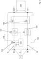
- Fig. 1 and 2 Each of the drawings shows a DC switching device 100 which is configured to couple a DC load 200 to a DC voltage source 4 via a positive conductor 8 and a negative conductor 10.
- the positive conductor 8 and the negative conductor 10 are each routed through the DC switching device 100.
- a DC voltage branch 2 is essentially configured between the DC voltage source 4 and the DC load 200.
- the positive and negative conductors 8, 10 can also be arranged on a printed circuit board, i.e., in particular, be designed as conductor tracks.
- the DC switching device 100 comprises, i.e., contains a first switching element 101 for coupling and uncoupling the DC load 200, which is a semiconductor-based, electronically controllable switching element integrated into the positive conductor 8 or the negative conductor 10; and a fuse 103 integrated in the other conductor.
- a semiconductor-based, electronically controllable switching element integrated into the positive conductor 8 or the negative conductor 10
- a fuse 103 integrated in the other conductor.
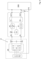
- Fig. 1 the semiconductor-based, electronically controllable switching element, additionally marked with "HS”, is inserted into the positive conductor 8 integrated and at Fig. 2 into the negative conductor 10. Accordingly, Fig. 1 an additional fuse 103 marked "SI" in the negative conductor 10 and at Fig. 2 integrated into the positive conductor.
- the DC voltage switching device 100 comprises a sensor 116, which is configured at least to detect the current flow of the conductor in which the first switching element 101 is integrated.
- the sensor 116 has a sensor element arranged in series with the first switching element 101 for detecting the current flow, i.e., the current flow of the conductor into which the first switching element 101 is also integrated.
- the sensor element detecting this current flow is additionally marked with "CS.”
- the evaluation device 118 of the DC switching device 100 is configured to compare the detected current flow with a threshold value and to actuate the first switching element 101 accordingly to decouple the DC load 200 when the threshold value is exceeded.
- the semiconductor-based switching element 101 is consequently switched off, and the DC load 200 is subsequently at least electrically decoupled and can no longer be operated via the DC voltage source 4.
- At least the first switching element 101, the fuse 103, and the evaluation device 118 can be contained in a common housing unit of the DC switching device 100, as in Fig. 1 indicated by the dashed outline, and in particular the fuse 103 can also be included in the DC switching device 100 in a replaceable or additional manner, so that it can be easily replaced in the event of "destruction.”
- the DC switching device 100 ensures the isolation of the fault location from the rest of the network in the event of an earth fault, particularly in network configurations in which the earth potential PE is not isolated from the active conductors, and it offers the possibility of safely isolating the fault in both the positive branch 8 and the negative branch 10.
- the controllable semiconductor switching element in one of the conductors i.e., in the positive or negative conductor, which is generally required for operational switching anyway, can switch off within a few ⁇ s and thus disconnect the DC voltage source 4 from the fault location before the current becomes too high.
- this semiconductor switching element is also expediently used as the first switching element for earth fault protection for this conductor, so that the disconnection can occur very quickly, i.e., in particular, within a few ⁇ s, and the current to be disconnected does not become too high.
- the current flow detected with respect to this conductor is evaluated by the evaluation device 118, which can, for example, contain a ⁇ C (microcontroller) or comparator circuit, and controls the first switching element 101, i.e., the semiconductor element, to decouple the DC voltage load when a threshold value is exceeded, i.e., switches it off.
- the first switching element 101, the sensor 116 and the evaluation device 118 form the earth fault protection for the corresponding conductor.
- fuse 103 is used for ground fault protection. Fuses with sufficient short-circuit strength are available, which may react more slowly but can safely interrupt very high currents (e.g., even several 10 kA).
- the advantage is that no additional semiconductor switching element is required, and consequently, a sensor to detect the current flow in the conductor into which the fuse is integrated is not necessary.
- Related evaluation and control are also not absolutely necessary for this conductor.
- the power loss of the fuse is significantly lower, which eliminates the need for complex cooling, as is usually required for a semiconductor switching element. For operational switching, no additional controllable semiconductor switching element is required in the second conductor anyway. Accordingly, the use of a fuse also results in cost advantages.
- the sensor element 116 arranged in series with the first switching element 101 could also be omitted, and the current flow of the conductor in which the first switching element 101 integrated by means of a sensor system arranged and set up in a different way.
- a suitable possibility according to the invention in addition to or as an alternative to a sensor element arranged in series with the first switching element 101, for detecting the current flow of the conductor in which the first switching element 101 is also integrated, consists in detecting the current flow of both conductors using a correspondingly arranged and configured sensor, i.e., in particular, detecting a current flow constituting the differential current or the sum current of the positive and negative conductors.
- the magnitudes of the currents in the positive and negative conductors are, in the optimal case, equal, i.e., the sum of the currents is zero or the difference in magnitude is zero. Consequently, in the event of an earth fault, a current flow of the conductor in which the first switching element 101 is integrated can also be (co-)detected by means of such a sensor.
- such a current flow can be detected by detecting a magnetic field that develops overall around the positive conductor 8 and the negative conductor 10.
- a sensor equipped with a Hall effect sensor element can be used.
- the positive conductor 8 and the negative conductor 10 can then, for example, be guided through a common through-opening of a ferrite core contained in the DC switching device, which is preferably split at one point and accommodates the sensor in the air gap consequently formed there. With the aid of such a ferrite core, the magnetic field lines can thus be expediently bundled and guided.
- a first switching element 101' may also be used, which comprises two electronically controllable switching units connected in series.
- operation of the DC load, ie, the current flow required for this with a corresponding connection to the DC voltage source is also fundamentally possible bidirectionally, and one of the anti-serially connected diodes of the semiconductor element can ensure the limitation of a respective current flow in one direction or the other.
- the evaluation device 118 can have an analog circuit, a discrete circuit or preferably also a ⁇ C (microcontroller) for evaluating the detected current flow, ie in particular for comparing the detected magnetic field with a threshold value and for activating the at least one switching element 101. If, depending on the design and/or field of application, the current flow exceeds or falls below a predetermined threshold value, the switching element, ie for example the one according to Fig. 1 shown switching element 101 for decoupling the load 200 from the source 4 is activated accordingly, ie in particular switched off.
- a ⁇ C microcontroller
- the switching element for coupling and decoupling the DC load 200 can additionally also comprise a second and a third switching element 106, in particular a second and third electromechanical switching element, wherein one of the second and third switching elements 106 is integrated into the positive conductor 8 and the other into the negative conductor 10.
- a galvanic decoupling of the load 200 from the source 4 can also be effected.
- the second and third switching elements 106 can consequently have relay contacts, in the Fig. 1 and 2 additionally marked with K1 or K2.
- such relay contacts are unsuitable for rapid disconnection, as the time until disconnection is in the ms range.
- the first switching element 101 or, additionally, the second and third switching elements 106 can be switched off by the evaluation device 118, thus electrically or galvanically decoupling the DC voltage branch from the DC voltage source 4. Furthermore, by switching off the second and third switching elements 106, current flow in both directions is prevented, whereas switching off only the first switching element 101 prevents current flow in only one current flow direction. The second and third switching elements 106 thus always ensure reliable galvanic isolation of the DC output from the DC input.
- the evaluation device 118 is further preferably configured to take into account the current amplitude and/or current direction, at least for switching off the first switching element 101, when a current flow change rate predetermined by the threshold value is exceeded.
- the rate of change of current flow and/or the current direction can also be compared with a threshold value, and if exceeded, this can lead to the deactivation of the first switching element (101).
- a comparison of the rate of change of current flow and/or the current direction is expediently carried out, and if the threshold value is exceeded, this leads to deactivation.
- the evaluation device 118 further comprises a signal output or a communication interface for outputting 119 a signal when the threshold value is exceeded and/or when the threshold value is not exceeded, but the detected current flow has a greater value in magnitude than a second threshold value that is smaller in magnitude than the threshold value.
- the evaluation device 118 is expediently designed and configured not only to electrically or additionally galvanically decouple the DC voltage load 200 or the entire DC voltage branch 2 from the DC voltage source 4 by means of corresponding activation commands to the switching element or elements, i.e., to switch it or them off, but also to electrically and/or galvanically couple the DC voltage load 200 or the entire DC voltage branch 2 to the DC voltage source 4 by means of corresponding activation commands to the switching element or elements, i.e., to switch it or them on.
- a command to the evaluation device 118 for effecting the switch-on based thereon can, according to an expedient embodiment, be received by the evaluation device 118, for example, also via a communication interface as described above or via another input interface, in particular a digital input.
- a DC voltage switching device as described above in various embodiments, it is therefore also possible to implement, in particular, a switching system in which the positive conductor 8 and the negative conductor 10 are connected to the DC voltage source 4 at an input IN+, IN- of the DC voltage switching device 100, and a DC voltage branch can be coupled to and uncoupled from the DC voltage load 200 at an output OUT+, OUT- of the DC voltage switching device 100 via the positive conductor 8 and the negative conductor 10 (cf. Fig. 1 ).
- the DC voltage of the DC voltage source 4 is usually generated from a three-phase AC network with L1, L2, L3 by means of a rectification GR, whereby the rectification can be carried out actively with a power electronic circuit or passively with diodes.
- Fig. 5 shows a highly simplified circuit diagram of a switching system according to the invention with a DC switching device and rectified three-phase AC network as DC voltage source 4 on the input side IN+, IN- and connected DC voltage load 200 on the Output side OUT+, OUT- as well as with indicated earth fault from PE to the negative line at the device output.
- a preferred switching system is outlined in a highly simplified manner, which has a first such DC switching device 100a, an input and an output, wherein the positive conductor and the negative conductor 10 input are connected to a DC voltage bus 4a as a DC voltage source and at the output via the positive conductor and the negative conductor a DC voltage branch 2a with a DC voltage load 200a can be coupled and uncoupled.
- Fig. 2 further comprises at least one further such DC switching device 100b with an input and an output, wherein in this further DC switching device 100b the positive conductor 8 and the negative conductor 10 are also connected equally at the input to the DC bus 4a and at the output a further DC voltage branch 2b with a DC load 200b can be coupled and uncoupled via the positive conductor 8 and the negative conductor 10.
- the DC load does not have to be a single load, but can be composed of a group of DC loads or be designed as a DC network with a plurality of DC loads operating over it.
- a MOSFET metal-oxide-semiconductor field-effect transistor
- IGBT Insulated Gate Bipolar Transistor
Landscapes
- Engineering & Computer Science (AREA)
- Power Engineering (AREA)
- Emergency Protection Circuit Devices (AREA)
Claims (9)
- Appareil de commutation à tension continue (100) permettant de coupler une charge de tension continue (200) à une source de tension continue (4) par l'intermédiaire d'un conducteur positif (8) et d'un conducteur négatif (10), dans lequel le conducteur positif (8) et le conducteur négatif (10) sont guidés à travers l'appareil de commutation à tension continue (100), comprenant :- un premier élément de commutation (101, 101') permettant de coupler et de découpler la charge de tension continue (200), lequel élément est un élément de commutation à commande électronique, à base de semi-conducteurs, intégré dans le conducteur positif (8) ou dans le conducteur négatif (10) ;- un fusible (103) intégré dans l'autre conducteur respectif ;- un capteur (116), permettant au moins de détecter le flux de courant du conducteur dans lequel est intégré le premier élément de commutation (101) ; et- un dispositif d'évaluation (118) relié au capteur (116) et au premier élément de commutation (101), caractérisé en ce que le dispositif d'évaluation (118) est conçu pour comparer le flux de courant détecté à une valeur seuil et pour amener le premier élément de commutation (101, 101') à découpler la charge de tension continue lorsque la valeur seuil est franchie.
- Appareil de commutation à tension continue (100) selon la revendication 1, dans lequel le capteur (116) possède un élément de capteur agencé en série avec le premier élément de commutation (101) pour détecter le flux de courant.
- Appareil de commutation à tension continue (100) selon l'une des revendications 1 ou 2, dans lequel le capteur (116) est agencé et conçu pour détecter le flux de courant des deux conducteurs, en particulier est agencé et conçu pour détecter un flux de courant formant le courant différentiel ou le courant cumulé des conducteurs positif et négatif.
- Appareil de commutation à tension continue (100) selon l'une des revendications 1 à 3, comprenant un deuxième et un troisième élément de commutation (106) permettant de coupler et découpler la charge de tension continue (200), en particulier un deuxième et un troisième élément de commutation électromécanique, dans lequel l'un parmi le deuxième et le troisième élément de commutation (106) est intégré dans le conducteur positif (8) et l'autre dans le conducteur négatif (10).
- Appareil de commutation à tension continue (100) selon l'une des revendications 1 à 4, dans lequel le premier élément de commutation (101') comprend deux unités de commutation à commande électronique branchées selon un montage antisérie.
- Appareil de commutation à tension continue (100) selon l'une des revendications 1 à 5, dans lequel au moins le premier élément de commutation (101, 101'), le fusible (103) et le dispositif d'évaluation (118) sont contenus dans un ensemble boîtier commun.
- Appareil de commutation à tension continue (100) selon l'une des revendications 1 à 6, dans lequel le conducteur positif (8) et le conducteur négatif (10) sont réalisés sous forme de pistes conductrices sur un circuit imprimé.
- Appareil de commutation à tension continue (100) selon l'une des revendications 1 à 7, dans lequel le dispositif d'évaluation (118) est conçu pour comparer, outre l'ampleur de courant, également la vitesse de variation du flux de courant et/ou la direction de courant à une valeur seuil et, en cas de dépassement, provoquer la coupure du premier élément de commutation (101).
- Système de commutation comportant un appareil de commutation à tension continue (100) selon l'une des revendications 1 à 7, dans lequel l'appareil de commutation à tension continue (100) possède une entrée et une sortie, dans lequel le conducteur positif (8) et le conducteur négatif (10) sont branchés à l'entrée à un bus de tension continue sous forme de source de tension continue (4) et une branche de tension continue comportant au moins une charge de tension continue peut être couplée et découplée à la sortie par l'intermédiaire du conducteur positif (8) et du conducteur négatif (10).
Applications Claiming Priority (2)
| Application Number | Priority Date | Filing Date | Title |
|---|---|---|---|
| BE20215522A BE1029566B1 (de) | 2021-07-05 | 2021-07-05 | Gleichspannungsschaltgerät mit Erdschlussschutz |
| PCT/EP2022/068358 WO2023280729A1 (fr) | 2021-07-05 | 2022-07-03 | Appareil de commutation à tension continue pourvu d'une protection contre les défauts à la terre |
Publications (2)
| Publication Number | Publication Date |
|---|---|
| EP4367698A1 EP4367698A1 (fr) | 2024-05-15 |
| EP4367698B1 true EP4367698B1 (fr) | 2025-06-18 |
Family
ID=76920449
Family Applications (1)
| Application Number | Title | Priority Date | Filing Date |
|---|---|---|---|
| EP22747287.5A Active EP4367698B1 (fr) | 2021-07-05 | 2022-07-03 | Appareil de commutation à tension continue pourvu d'une protection contre les défauts à la terre |
Country Status (5)
| Country | Link |
|---|---|
| US (1) | US12081012B2 (fr) |
| EP (1) | EP4367698B1 (fr) |
| CN (1) | CN117581323A (fr) |
| BE (1) | BE1029566B1 (fr) |
| WO (1) | WO2023280729A1 (fr) |
Families Citing this family (2)
| Publication number | Priority date | Publication date | Assignee | Title |
|---|---|---|---|---|
| BE1029560B1 (de) * | 2021-07-05 | 2023-02-06 | Phoenix Contact Gmbh & Co | Fehlerstromüberwachung für ein Gleichspannungsschaltgerät |
| LU505555B1 (de) * | 2023-11-17 | 2025-05-19 | Phoenix Contact Gmbh & Co | Trennschalter |
Family Cites Families (11)
| Publication number | Priority date | Publication date | Assignee | Title |
|---|---|---|---|---|
| WO2003103110A1 (fr) * | 2002-06-04 | 2003-12-11 | Sure Power Corporation | Sectionneur de charge en courant continu |
| US8526143B2 (en) * | 2009-05-14 | 2013-09-03 | Siemens Industry, Inc. | Methods and appraratus for ground fault circuit interrupt detection using a single transformer |
| DE102013214726A1 (de) * | 2013-07-29 | 2015-01-29 | Bayerische Motoren Werke Aktiengesellschaft | Anordnung zur elektrischen Absicherung eines potentiellen Kurzschlusses bzw. einer Überlast in einem Gleichstromnetz mit systembedingten, variablem Quellinnenwiderstand |
| DE102014102352A1 (de) * | 2014-02-24 | 2015-08-27 | Ge Energy Power Conversion Technology Limited | Batteriespeichersystem mit Störlichtbogenschutz, Energieumwandlungssystem und Schutzverfahren |
| GB201610901D0 (en) * | 2016-06-22 | 2016-08-03 | Eaton Ind Austria Gmbh | Hybrid DC circuit breaker |
| CN106443293A (zh) * | 2016-08-15 | 2017-02-22 | 国家电网公司 | 一种直流接地故障在线检测及报警装置 |
| EP3379725A1 (fr) | 2017-03-23 | 2018-09-26 | Siemens Aktiengesellschaft | Procédé de commande d'un commutateur à courant continu, commutateur à courant continu et système de tension continue |
| KR102185036B1 (ko) * | 2018-04-30 | 2020-12-01 | 엘에스일렉트릭(주) | 차단기 제어 모듈 |
| DE102019203982B4 (de) * | 2019-03-22 | 2020-12-31 | Siemens Aktiengesellschaft | Schalteinrichtung für einen Gleichspannungsstromkreis |
| DE102019203977B4 (de) | 2019-03-22 | 2020-12-24 | Siemens Aktiengesellschaft | Schutzschalteinrichtung für Gleichspannung und Gleichspannungsabzweig mit Schutzschalteinrichtung |
| EP3723223A1 (fr) * | 2019-04-08 | 2020-10-14 | Siemens Aktiengesellschaft | Emplacements d'une perte à la terre dans un réseau à courant continue |
-
2021
- 2021-07-05 BE BE20215522A patent/BE1029566B1/de not_active IP Right Cessation
-
2022
- 2022-07-03 CN CN202280044856.1A patent/CN117581323A/zh active Pending
- 2022-07-03 WO PCT/EP2022/068358 patent/WO2023280729A1/fr not_active Ceased
- 2022-07-03 EP EP22747287.5A patent/EP4367698B1/fr active Active
- 2022-07-03 US US18/577,178 patent/US12081012B2/en active Active
Also Published As
| Publication number | Publication date |
|---|---|
| BE1029566B1 (de) | 2023-02-06 |
| EP4367698A1 (fr) | 2024-05-15 |
| BE1029566A1 (de) | 2023-01-30 |
| WO2023280729A1 (fr) | 2023-01-12 |
| US12081012B2 (en) | 2024-09-03 |
| CN117581323A (zh) | 2024-02-20 |
| US20240266820A1 (en) | 2024-08-08 |
Similar Documents
| Publication | Publication Date | Title |
|---|---|---|
| EP2980659B1 (fr) | Dispositif et procédé destinés à la surveillance et la commutation d'un circuit de charge | |
| DE102010007452A1 (de) | Schaltentlastung für einen Trennschalter | |
| EP2980660B1 (fr) | Procédé et dispositif de surveillance et de commutation d'un circuit de charge | |
| EP4367698B1 (fr) | Appareil de commutation à tension continue pourvu d'une protection contre les défauts à la terre | |
| EP4367765B1 (fr) | Surveillance de courant de défaut pour un appareil de commutation à tension continue | |
| EP3501100B1 (fr) | Dispositif de séparation pour une chaîne photovoltaïque | |
| EP2523296A1 (fr) | Agencement de commutation pour la préparation d'une protection contre les surtensions et son procédé de fonctionnement | |
| DE3930091A1 (de) | Schaltungsanordnung zum schutz eines stromverbrauchers vor falschpolung seiner speisespannung | |
| WO2023011768A1 (fr) | Unité de disjoncteur | |
| DE10361641A1 (de) | Aktive Sicherheitsschaltung mit Lasten, die durch Festkörperrelais geschützt werden | |
| DE102021117296A1 (de) | Gleichspannungsschaltgerät mit Erdschlussschutz | |
| DE102011053728A9 (de) | Batteriesystem und Verfahren zum Abschalten von in Serie geschalteten Energiespeichermodulen einer Batterie eines Batteriesystems | |
| EP3709513B1 (fr) | Dispositif de commutation ainsi que procédé de fonctionnement d'un dispositif de commutation | |
| DE102021117260A1 (de) | Fehlerstromüberwachung für ein Gleichspannungsschaltgerät | |
| EP1665492B1 (fr) | Circuit de coupure rapide d'interrupteurs basse tension | |
| BE1030845B1 (de) | Gleichspannungsschaltgerät mit integriertem Unterbrechungsmechanismus | |
| DE102017101378A1 (de) | Stromkreisschutzsytem | |
| DE202014004493U1 (de) | Elektronisches Relais | |
| EP1906534A1 (fr) | Procédé pour déterminer un seuil de commutation et circuit associé. | |
| DE102022122463A1 (de) | Gleichspannungsschaltgerät mit integriertem Unterbrechungsmechanismus | |
| WO2014060513A1 (fr) | Agencement de circuit de protection et procédé de protection d'un appareillage électrique, ainsi que dispositif équipé du circuit à protéger et de l'agencement de circuit de protection | |
| EP3417534B1 (fr) | Convertisseur modulaire multiniveaux | |
| DE102013214593A1 (de) | Schaltereinrichtung | |
| DE102023104757A1 (de) | Überspannungsschutzanordnung für ein elektrisches Gerät | |
| DE3810792C2 (fr) |
Legal Events
| Date | Code | Title | Description |
|---|---|---|---|
| STAA | Information on the status of an ep patent application or granted ep patent |
Free format text: STATUS: UNKNOWN |
|
| STAA | Information on the status of an ep patent application or granted ep patent |
Free format text: STATUS: THE INTERNATIONAL PUBLICATION HAS BEEN MADE |
|
| PUAI | Public reference made under article 153(3) epc to a published international application that has entered the european phase |
Free format text: ORIGINAL CODE: 0009012 |
|
| STAA | Information on the status of an ep patent application or granted ep patent |
Free format text: STATUS: REQUEST FOR EXAMINATION WAS MADE |
|
| 17P | Request for examination filed |
Effective date: 20240123 |
|
| AK | Designated contracting states |
Kind code of ref document: A1 Designated state(s): AL AT BE BG CH CY CZ DE DK EE ES FI FR GB GR HR HU IE IS IT LI LT LU LV MC MK MT NL NO PL PT RO RS SE SI SK SM TR |
|
| DAV | Request for validation of the european patent (deleted) | ||
| DAX | Request for extension of the european patent (deleted) | ||
| GRAP | Despatch of communication of intention to grant a patent |
Free format text: ORIGINAL CODE: EPIDOSNIGR1 |
|
| STAA | Information on the status of an ep patent application or granted ep patent |
Free format text: STATUS: GRANT OF PATENT IS INTENDED |
|
| RIC1 | Information provided on ipc code assigned before grant |
Ipc: H02H 3/33 20060101ALI20241216BHEP Ipc: H02H 3/087 20060101ALI20241216BHEP Ipc: H02H 7/26 20060101ALI20241216BHEP Ipc: H01H 33/59 20060101ALI20241216BHEP Ipc: H01H 9/54 20060101AFI20241216BHEP |
|
| INTG | Intention to grant announced |
Effective date: 20250113 |
|
| GRAS | Grant fee paid |
Free format text: ORIGINAL CODE: EPIDOSNIGR3 |
|
| GRAA | (expected) grant |
Free format text: ORIGINAL CODE: 0009210 |
|
| STAA | Information on the status of an ep patent application or granted ep patent |
Free format text: STATUS: THE PATENT HAS BEEN GRANTED |
|
| P01 | Opt-out of the competence of the unified patent court (upc) registered |
Free format text: CASE NUMBER: APP_18147/2025 Effective date: 20250414 |
|
| AK | Designated contracting states |
Kind code of ref document: B1 Designated state(s): AL AT BE BG CH CY CZ DE DK EE ES FI FR GB GR HR HU IE IS IT LI LT LU LV MC MK MT NL NO PL PT RO RS SE SI SK SM TR |
|
| REG | Reference to a national code |
Ref country code: GB Ref legal event code: FG4D Free format text: NOT ENGLISH |
|
| REG | Reference to a national code |
Ref country code: CH Ref legal event code: EP |
|
| REG | Reference to a national code |
Ref country code: DE Ref legal event code: R096 Ref document number: 502022004349 Country of ref document: DE |
|
| REG | Reference to a national code |
Ref country code: CH Ref legal event code: EP |
|
| REG | Reference to a national code |
Ref country code: IE Ref legal event code: FG4D Free format text: LANGUAGE OF EP DOCUMENT: GERMAN |
|
| PG25 | Lapsed in a contracting state [announced via postgrant information from national office to epo] |
Ref country code: FI Free format text: LAPSE BECAUSE OF FAILURE TO SUBMIT A TRANSLATION OF THE DESCRIPTION OR TO PAY THE FEE WITHIN THE PRESCRIBED TIME-LIMIT Effective date: 20250618 |
|
| PGFP | Annual fee paid to national office [announced via postgrant information from national office to epo] |
Ref country code: DE Payment date: 20250926 Year of fee payment: 4 |
|
| REG | Reference to a national code |
Ref country code: LT Ref legal event code: MG9D |
|
| PG25 | Lapsed in a contracting state [announced via postgrant information from national office to epo] |
Ref country code: NO Free format text: LAPSE BECAUSE OF FAILURE TO SUBMIT A TRANSLATION OF THE DESCRIPTION OR TO PAY THE FEE WITHIN THE PRESCRIBED TIME-LIMIT Effective date: 20250918 Ref country code: GR Free format text: LAPSE BECAUSE OF FAILURE TO SUBMIT A TRANSLATION OF THE DESCRIPTION OR TO PAY THE FEE WITHIN THE PRESCRIBED TIME-LIMIT Effective date: 20250919 |
|
| PG25 | Lapsed in a contracting state [announced via postgrant information from national office to epo] |
Ref country code: BG Free format text: LAPSE BECAUSE OF FAILURE TO SUBMIT A TRANSLATION OF THE DESCRIPTION OR TO PAY THE FEE WITHIN THE PRESCRIBED TIME-LIMIT Effective date: 20250618 |
|
| PG25 | Lapsed in a contracting state [announced via postgrant information from national office to epo] |
Ref country code: HR Free format text: LAPSE BECAUSE OF FAILURE TO SUBMIT A TRANSLATION OF THE DESCRIPTION OR TO PAY THE FEE WITHIN THE PRESCRIBED TIME-LIMIT Effective date: 20250618 |
|
| PGFP | Annual fee paid to national office [announced via postgrant information from national office to epo] |
Ref country code: AT Payment date: 20251020 Year of fee payment: 4 |
|
| PG25 | Lapsed in a contracting state [announced via postgrant information from national office to epo] |
Ref country code: RS Free format text: LAPSE BECAUSE OF FAILURE TO SUBMIT A TRANSLATION OF THE DESCRIPTION OR TO PAY THE FEE WITHIN THE PRESCRIBED TIME-LIMIT Effective date: 20250918 |
|
| REG | Reference to a national code |
Ref country code: NL Ref legal event code: MP Effective date: 20250618 |
|
| PG25 | Lapsed in a contracting state [announced via postgrant information from national office to epo] |
Ref country code: LV Free format text: LAPSE BECAUSE OF FAILURE TO SUBMIT A TRANSLATION OF THE DESCRIPTION OR TO PAY THE FEE WITHIN THE PRESCRIBED TIME-LIMIT Effective date: 20250618 |
|
| PG25 | Lapsed in a contracting state [announced via postgrant information from national office to epo] |
Ref country code: NL Free format text: LAPSE BECAUSE OF FAILURE TO SUBMIT A TRANSLATION OF THE DESCRIPTION OR TO PAY THE FEE WITHIN THE PRESCRIBED TIME-LIMIT Effective date: 20250618 |
|
| PG25 | Lapsed in a contracting state [announced via postgrant information from national office to epo] |
Ref country code: PT Free format text: LAPSE BECAUSE OF FAILURE TO SUBMIT A TRANSLATION OF THE DESCRIPTION OR TO PAY THE FEE WITHIN THE PRESCRIBED TIME-LIMIT Effective date: 20251020 |