EP4367358B1 - System und verfahren zur positions- und ausrichtungserkennung einer bohrlochvorrichtung - Google Patents
System und verfahren zur positions- und ausrichtungserkennung einer bohrlochvorrichtung Download PDFInfo
- Publication number
- EP4367358B1 EP4367358B1 EP22731208.9A EP22731208A EP4367358B1 EP 4367358 B1 EP4367358 B1 EP 4367358B1 EP 22731208 A EP22731208 A EP 22731208A EP 4367358 B1 EP4367358 B1 EP 4367358B1
- Authority
- EP
- European Patent Office
- Prior art keywords
- platform
- body element
- gravity
- drill
- inner body
- Prior art date
- Legal status (The legal status is an assumption and is not a legal conclusion. Google has not performed a legal analysis and makes no representation as to the accuracy of the status listed.)
- Active
Links
Images


Classifications
-
- E—FIXED CONSTRUCTIONS
- E21—EARTH OR ROCK DRILLING; MINING
- E21B—EARTH OR ROCK DRILLING; OBTAINING OIL, GAS, WATER, SOLUBLE OR MELTABLE MATERIALS OR A SLURRY OF MINERALS FROM WELLS
- E21B47/00—Survey of boreholes or wells
- E21B47/02—Determining slope or direction
- E21B47/024—Determining slope or direction of devices in the borehole
-
- E—FIXED CONSTRUCTIONS
- E21—EARTH OR ROCK DRILLING; MINING
- E21B—EARTH OR ROCK DRILLING; OBTAINING OIL, GAS, WATER, SOLUBLE OR MELTABLE MATERIALS OR A SLURRY OF MINERALS FROM WELLS
- E21B44/00—Automatic control systems specially adapted for drilling operations, i.e. self-operating systems which function to carry out or modify a drilling operation without intervention of a human operator, e.g. computer-controlled drilling systems; Systems specially adapted for monitoring a plurality of drilling variables or conditions
- E21B44/005—Below-ground automatic control systems
-
- E—FIXED CONSTRUCTIONS
- E21—EARTH OR ROCK DRILLING; MINING
- E21B—EARTH OR ROCK DRILLING; OBTAINING OIL, GAS, WATER, SOLUBLE OR MELTABLE MATERIALS OR A SLURRY OF MINERALS FROM WELLS
- E21B47/00—Survey of boreholes or wells
- E21B47/02—Determining slope or direction
- E21B47/022—Determining slope or direction of the borehole, e.g. using geomagnetism
-
- E—FIXED CONSTRUCTIONS
- E21—EARTH OR ROCK DRILLING; MINING
- E21B—EARTH OR ROCK DRILLING; OBTAINING OIL, GAS, WATER, SOLUBLE OR MELTABLE MATERIALS OR A SLURRY OF MINERALS FROM WELLS
- E21B7/00—Special methods or apparatus for drilling
- E21B7/04—Directional drilling
- E21B7/06—Deflecting the direction of boreholes
- E21B7/062—Deflecting the direction of boreholes the tool shaft rotating inside a non-rotating guide travelling with the shaft
-
- E—FIXED CONSTRUCTIONS
- E21—EARTH OR ROCK DRILLING; MINING
- E21B—EARTH OR ROCK DRILLING; OBTAINING OIL, GAS, WATER, SOLUBLE OR MELTABLE MATERIALS OR A SLURRY OF MINERALS FROM WELLS
- E21B7/00—Special methods or apparatus for drilling
- E21B7/04—Directional drilling
- E21B7/06—Deflecting the direction of boreholes
- E21B7/064—Deflecting the direction of boreholes specially adapted drill bits therefor
-
- E—FIXED CONSTRUCTIONS
- E21—EARTH OR ROCK DRILLING; MINING
- E21B—EARTH OR ROCK DRILLING; OBTAINING OIL, GAS, WATER, SOLUBLE OR MELTABLE MATERIALS OR A SLURRY OF MINERALS FROM WELLS
- E21B7/00—Special methods or apparatus for drilling
- E21B7/04—Directional drilling
- E21B7/06—Deflecting the direction of boreholes
- E21B7/067—Deflecting the direction of boreholes with means for locking sections of a pipe or of a guide for a shaft in angular relation, e.g. adjustable bent sub
Definitions
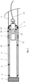
- the orientation system for RSS drills thus comprises the inner body element (11), and a magnetic reference element (14) fixed to the non-rotating outer body element (1) in a known rotational position relative to the deflection mechanism (8).
- the core tube assembly holding the inner body element (11) connects to a seat (13) in a rotationally random position inside the drive shaft, drill rod or couplings thereof, the inner body element (11) will thereby substantially be rotating along with the drive shaft during drilling operation.
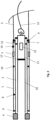
- the inner body element houses an instrument section (15) according to the invention, that determine the rotational position of the reference element (14) relative to the direction of earth gravity. It should be emphasized that the instrument section (15) can be arranged at either side of the bearing (17) or at any other suitable location of the inner body element.
- Said platform (23) houses at least one gravity sensor measuring the direction of earth's gravity relative to the orientation of said platform (23).
- the gravity sensor will thus be kept substantially stationary and in a known rotational position relative to the reference magnet (14) also during drilling operations.
- a processor and a battery are fixed to the inner body element (15), for retrieving data from the gravity sensor, using such data for calculating and/or determining the rotational orientation of the platform (23), and hereby the rotational orientation of the fixed reference point element (14) relative to earth gravity, denoted as TF (Tool Face) in Figure 4 .
- TF Tool Face
- FIG 5 shows a preferred configuration of the power supply system to the gravity sensor, using wireless (24) according to the invention, but connection through the respective pair of suspension means (20) such as but not limited to suspension bearings (20) as shown in Figure 6 might also be feasible.
- the gravity sensor communicates with the processor via wireless communication (25), but a wired connection might also be feasible by using a preferably contactless slip ring contact. It is commonly understood that wireless communication requires a communication module arranged at the platform and a receiver at the main electronic board. It is to be understood that wireless connections both for data and power can be achieved by means of "state of the art" wireless technology.
- data from the processor can be accessed via Bluetooth (BT) or other wireless communication systems while the inner body element (11) is at surface, but it might also be feasible by using a cable connection from downhole or at surface or means for wireless down hole communication.
- BT Bluetooth
- other wireless communication systems while the inner body element (11) is at surface, but it might also be feasible by using a cable connection from downhole or at surface or means for wireless down hole communication.
- Figure 7 shows the platform (23) suspended rotationally free inside housing, carrying a gravity sensor and a magnetic field sensor, connected to an alignment device such as an electric motor (27) which rotational speed is controlled by data provided from the gravity sensor.
- Said motor will in continuous mode run the cradle CCW (Counter Clock Wise) with the same speed as the drive shaft is running CW (Clock Wise) during drilling, in order to keep the platform rotationally fixed in a known position relative to the earth gravity.
- the motor (27) can be set to conditional mode, meaning that the motor (27) is placing the platform (23) rotationally fixed in a known position relative to earth gravity at certain times or events such as time intervals or when the drill is in standstill mode. If the rotational speed of the drilling shaft is known or controlled in other way the motor (27) may simply be synchronized with the known speed without using a magnetic field sensor.
- the rotational speed of the motor is controlled by data provided from the magnetic field sensor to keep the platform (23) rotationally fixed in a known position relative to the reference point element and the gravity sensor to measure the rotational position of the platform (23) relative to earth gravity.
- the motorized embodiments are beneficial in the way that it does not relay directly on magnetic forces to keep the platform in position, thus its more robust and less sensitive to the mass of the platform.
- the present invention thus relates to a system for identifying or monitoring the orientation and position of a rotary steerable system drill especially for controlled drilling in bedrock or corresponding geological structures.
- the system may therefor preferably comprise:
- the inner body element includes;
- the platform (23) includes only the alignment magnet (19), the gravity sensor and connections allowing communication with the main electronic board (21), so as to reduce the weight of the platform to a minimum.
- the section of the drive shaft (3) surrounding the alignment magnet (19) or field sensor may be made of a non-magnetic material.
- the gravity sensor communicates with the processor via wireless communication.
- wireless communication requires that a communication module is arranged on the platform holding the sensor/s and a receiver at the main electronic board.
- the system may also include a communication interface for retrieving the stored data from the processor at any time to determine the drilling direction at a given time or periods of time and/or input for manual or autonomous downhole adjustment of drill parameters such as degree of deflection and tool face.
- the main electronic board can also be made suitable for acting as a processing hub for a range or sensors and devices.
- the word “directly” means that the rotational position of the reference point element (14) relative to the direction of earth gravity, is determined directly and exclusively by looking at data provided by the gravity sensor, without this excluding alternative embodiments where other sensors such as a magnetic field sensor are being used in a separate process of positioning the cradle or platform in a known position relative to the reference point element (14).
- the word "indirectly” means that the gravity sensor is not directly used to determinate the rotational position of the reference point element (14) relative to the direction of earth gravity, instead the gravity sensor is used in separate process of positioning the cradle or platform in a known position relative to earth gravity.
- the alignment device is at least one alignment magnet seated on the platform (23).
- the alignment magnet/s (19) being configured to rotationally align said platform (23) in a known rotational position relative to the reference point element (14) due to the magnetic forces imposed between the magnets.
- the alignment device includes a motor (27) connected to the platform (23) being configured to align the platform (23) in a known rotational position relative to the reference point magnet (14) or the direction of earth's gravity.
- the alignment device may then include at least one magnetic field sensor seated on platform (23) being configured to measure the rotational position of the reference point magnet (14) relative to the platform.
- the alignment device thus is configured to use the magnetic field sensor data as input to the motor (27) to align the platform (23) in a known rotational position relative to the reference point element (14), and the gravity sensor to measure the rotational position of the platform (23) relative to earth gravity.
- the section the drive shaft (3) surrounding the alignment magnet/s (19) or field sensor may be made of a non-magnetic material.
- the alignment device may include using the gravity sensor data as input to control the motor (27) to align the platform (23) in a known rotational position relative to earth gravity, and the magnetic field sensor to measure the rotational position of the reference point element (14) relative to the cradle or platform (23).
- the system may also include a communication interface for retrieving the stored data at any time, so as to determine the drilling direction at a given time or periods of time and/or input for manual or autonomous downhole adjustment of drill parameters such as degree of deflection and tool face.
- the at least one battery and the at least one processor is located outside the platform holding the sensor/s, wherein the said processor and said power supply is connected to the platform (23) preferably wirelessly or by contactless sliprings.
Landscapes
- Geology (AREA)
- Life Sciences & Earth Sciences (AREA)
- Engineering & Computer Science (AREA)
- Mining & Mineral Resources (AREA)
- Physics & Mathematics (AREA)
- Environmental & Geological Engineering (AREA)
- Fluid Mechanics (AREA)
- Geochemistry & Mineralogy (AREA)
- General Life Sciences & Earth Sciences (AREA)
- Geophysics (AREA)
- Earth Drilling (AREA)
- Excavating Of Shafts Or Tunnels (AREA)
- Geophysics And Detection Of Objects (AREA)
- Container, Conveyance, Adherence, Positioning, Of Wafer (AREA)
- Burglar Alarm Systems (AREA)
Claims (9)
- System zum Identifizieren oder Überwachen der Ausrichtung und Position eines rotierenden lenkbaren Bohrers zum Bohren in Felsgestein, das System umfassend;- ein im Wesentlichen nicht rotierendes äußeres Körperelement (1), das mindestens einen Referenzpunktmagneten (14) beherbergt, und- eine rotierende Antriebswelle (3), die innerhalb des äußeren Körperelements (1) angeordnet ist, die mit einem Bohrmeißel (4) an ihrem ersten Ende und mit der Bohrstange (5) oder einer Kopplung davon an ihrem zweiten Ende und einem Ablenkmechanismus (8) verbunden ist, um den Bohrmeißel (4) zu kippen oder zu schieben und dadurch eine Änderung in der Bohrrichtung zu erreichen, und- ein inneres Körperelement (11), das in einer rotierend zufälligen Position innerhalb der Antriebswelle (3), der Bohrstange (5) oder der Kopplung davon sitzt, und wobei das innere Körperelement (11) dauerhaft sitzen oder mittels eines Drahtseils von der Oberfläche geborgen werden kann,dadurch gekennzeichnet, dass das System ebenso eine Antirotationsvorrichtung (2) umfasst, die verhindert, dass das Element (1) des äußeren Körpers frei rotiert, dem äußeren Körperelement (1) jedoch ermöglicht, sich in die Längsrichtung während des Bohrens zu bewegen, und
wobei das innere Körperelement (11) einschließt:- eine Plattform (23), die im Wesentlichen konzentrisch und rotierend frei innerhalb des inneren Körperelements (11) aufgehängt ist,- wobei die Plattform (23) ferner mindestens einen Schwerkraftsensor beherbergt, um jederzeit die Richtung der Erdanziehungskraft relativ zu der Plattform (23) zu messen, und- die Plattform (23) ferner mindestens eine Ausrichtungsvorrichtung einschließt, die mit der Plattform (23) verbunden ist, die konfiguriert ist, um die Plattform mit dem Referenzpunktmagneten (14) auszurichten, und- eine Hauptelektronikplatine (21), die in einer festen Beziehung zu dem inneren Körperelement (11) positioniert ist, umfassend mindestens einen Prozessor zum Abrufen und Speichern von Daten von dem Schwerkraftsensor, wobei die Elektronikplatine (21) konfiguriert ist, um die Schwerkraftdaten direkt oder indirekt jederzeit zum Berechnen und/oder Bestimmen der Rotationsausrichtung des Referenzpunktmagneten (14) relativ zu der Richtung der Erdanziehungskraft und dadurch der Rotationsposition des Ablenkmechanismus (8) relativ zu der Richtung der Erdanziehungskraft zu verwenden, die die Bohrrichtung bestimmt,- mindestens eine Leistungsversorgungseinheit (26), die in einer festen Beziehung zu dem inneren Körperelement (11) positioniert ist, wie eine Batterie oder ein Leistungsgenerator, die den Schwerkraftsensor und die Hauptelektronikplatine (21) mit Leistung versorgen. - System nach Anspruch 1, wobei der mindestens eine Schwerkraftsensor ein dreiachsiger Beschleunigungsmesser ist.
- System nach Anspruch 1, wobei die Ausrichtungsvorrichtung ein Magnet (19) ist, der an der Plattform (23) befestigt ist.
- System nach Anspruch 1, wobei die Ausrichtungsvorrichtung ein Ausrichtungsmotor (27) ist, der mittels einer Welle mit der Plattform (23) gekoppelt ist.
- System nach Anspruch 1, wobei das System eine Schnittstelle zum jederzeit Abrufen der gespeicherten Daten einschließt, um die Bohrrichtung zu einem gegebenen Zeitpunkt oder in Zeiträumen und/oder eine Eingabe für eine manuelle oder autonome Abwärtsbohrungsanpassung von Bohrparametern wie Ablenkungsgrad und Werkzeugfläche zu bestimmen.
- System nach Anspruch 1, wobei die Plattform elektrische Leistung drahtlos empfängt.
- System nach Anspruch 1, wobei die Plattform (23) elektrische Leistung durch das jeweilige Paar von Aufhängungsmitteln (20) empfängt, das aus einem elektrisch leitfähigen Material hergestellt ist.
- System nach Anspruch 1, wobei der mindestens eine Schwerkraftsensor über eine drahtlose Kommunikation mit dem Prozessor kommuniziert.
- System nach Anspruch 1, wobei mindestens ein Abschnitt der Antriebswelle (3), der den Ausrichtungsmagneten (19) umgibt, aus einem nicht magnetischen Material hergestellt ist.
Applications Claiming Priority (2)
| Application Number | Priority Date | Filing Date | Title |
|---|---|---|---|
| NO20210892A NO20210892A1 (de) | 2021-07-09 | 2021-07-09 | |
| PCT/EP2022/064829 WO2023280480A1 (en) | 2021-07-09 | 2022-05-31 | System and method for position and orientation detection of a downhole device |
Publications (2)
| Publication Number | Publication Date |
|---|---|
| EP4367358A1 EP4367358A1 (de) | 2024-05-15 |
| EP4367358B1 true EP4367358B1 (de) | 2025-03-19 |
Family
ID=82100506
Family Applications (1)
| Application Number | Title | Priority Date | Filing Date |
|---|---|---|---|
| EP22731208.9A Active EP4367358B1 (de) | 2021-07-09 | 2022-05-31 | System und verfahren zur positions- und ausrichtungserkennung einer bohrlochvorrichtung |
Country Status (8)
| Country | Link |
|---|---|
| US (1) | US12241364B2 (de) |
| EP (1) | EP4367358B1 (de) |
| AU (1) | AU2022305715A1 (de) |
| CA (1) | CA3223392A1 (de) |
| FI (1) | FI4367358T3 (de) |
| MX (1) | MX2024000523A (de) |
| NO (1) | NO20210892A1 (de) |
| WO (1) | WO2023280480A1 (de) |
Families Citing this family (1)
| Publication number | Priority date | Publication date | Assignee | Title |
|---|---|---|---|---|
| NO348130B1 (en) | 2023-04-21 | 2024-09-02 | Aziwell As | A system and a method for down hole control of devices within rotary steerable drilling assembly |
Citations (2)
| Publication number | Priority date | Publication date | Assignee | Title |
|---|---|---|---|---|
| EP3180496B1 (de) * | 2014-08-14 | 2020-11-04 | Huygens As | System und verfahren zur erkennung der position und ausrichtung einer bohrlochvorrichtung |
| EP3710669B1 (de) * | 2017-11-17 | 2021-10-13 | Huygens As | Richtkernbohrervorrichtung |
Family Cites Families (12)
| Publication number | Priority date | Publication date | Assignee | Title |
|---|---|---|---|---|
| US2207505A (en) * | 1935-04-05 | 1940-07-09 | Carl St J Bremner | Drill pipe orienting tool |
| US4537067A (en) * | 1982-11-18 | 1985-08-27 | Wilson Industries, Inc. | Inertial borehole survey system |
| US6158529A (en) * | 1998-12-11 | 2000-12-12 | Schlumberger Technology Corporation | Rotary steerable well drilling system utilizing sliding sleeve |
| CA2351978C (en) | 2001-06-28 | 2006-03-14 | Halliburton Energy Services, Inc. | Drilling direction control device |
| US7556105B2 (en) * | 2002-05-15 | 2009-07-07 | Baker Hughes Incorporated | Closed loop drilling assembly with electronics outside a non-rotating sleeve |
| CA2616154C (en) | 2005-08-03 | 2012-10-30 | Halliburton Energy Services, Inc. | Orientation sensing apparatus and a method for determining an orientation |
| US7725263B2 (en) | 2007-05-22 | 2010-05-25 | Smith International, Inc. | Gravity azimuth measurement at a non-rotating housing |
| RU2482274C2 (ru) * | 2008-10-31 | 2013-05-20 | Шлюмбергер Текнолоджи Б.В. | Интегрированная система кернового бурения |
| DE102011103220B3 (de) * | 2011-06-01 | 2012-10-18 | Tracto-Technik Gmbh & Co. Kg | Doppelrohrgestängeschuss mit einer im Doppelrohrgestängeschuss angeordneten Sonde, ein Horizontalbohrgerät und ein Sondengehäuse |
| US9022141B2 (en) * | 2011-11-20 | 2015-05-05 | Schlumberger Technology Corporation | Directional drilling attitude hold controller |
| US9650834B1 (en) * | 2016-01-06 | 2017-05-16 | Isodrill, Llc | Downhole apparatus and method for torsional oscillation abatement |
| US11230887B2 (en) * | 2018-03-05 | 2022-01-25 | Baker Hughes, A Ge Company, Llc | Enclosed module for a downhole system |
-
2021
- 2021-07-09 NO NO20210892A patent/NO20210892A1/en unknown
-
2022
- 2022-05-31 WO PCT/EP2022/064829 patent/WO2023280480A1/en not_active Ceased
- 2022-05-31 EP EP22731208.9A patent/EP4367358B1/de active Active
- 2022-05-31 US US18/566,815 patent/US12241364B2/en active Active
- 2022-05-31 MX MX2024000523A patent/MX2024000523A/es unknown
- 2022-05-31 CA CA3223392A patent/CA3223392A1/en active Pending
- 2022-05-31 FI FIEP22731208.9T patent/FI4367358T3/fi active
- 2022-05-31 AU AU2022305715A patent/AU2022305715A1/en active Pending
Patent Citations (2)
| Publication number | Priority date | Publication date | Assignee | Title |
|---|---|---|---|---|
| EP3180496B1 (de) * | 2014-08-14 | 2020-11-04 | Huygens As | System und verfahren zur erkennung der position und ausrichtung einer bohrlochvorrichtung |
| EP3710669B1 (de) * | 2017-11-17 | 2021-10-13 | Huygens As | Richtkernbohrervorrichtung |
Also Published As
| Publication number | Publication date |
|---|---|
| NO20210892A1 (de) | 2023-01-10 |
| EP4367358A1 (de) | 2024-05-15 |
| WO2023280480A1 (en) | 2023-01-12 |
| CA3223392A1 (en) | 2023-01-12 |
| US20240271522A1 (en) | 2024-08-15 |
| MX2024000523A (es) | 2024-02-02 |
| AU2022305715A1 (en) | 2023-12-14 |
| FI4367358T3 (fi) | 2025-05-13 |
| US12241364B2 (en) | 2025-03-04 |
Similar Documents
| Publication | Publication Date | Title |
|---|---|---|
| EP0172599B1 (de) | Vorrichtung und Verfahren zur Vermessung von Bohrlöchern | |
| US3753296A (en) | Well mapping apparatus and method | |
| US6192748B1 (en) | Dynamic orienting reference system for directional drilling | |
| US4199869A (en) | Mapping apparatus employing two input axis gyroscopic means | |
| CA2771653C (en) | Gyroscopic system for determination of downhole position | |
| US6816788B2 (en) | Inertially-stabilized magnetometer measuring apparatus for use in a borehole rotary environment | |
| EP2694914B1 (de) | Verfahren und vorrichtung zur orientierungsbestimmung unter verwendung einer vielzahl von drehratensensoren und beschleunigungsaufnehmern | |
| US4293046A (en) | Survey apparatus, method employing angular accelerometer | |
| EP1709293A1 (de) | Verfahren und vorrichtung zur verbesserung der richtungsgenauigkeit und -steuerung unter verwendung von grundbohrungsanordnungsbiegemessungen | |
| CA1108892A (en) | Survey apparatus and method employing rate-of-turn and free gyroscopes | |
| US4706388A (en) | Borehole initial alignment and change determination | |
| EP4367358B1 (de) | System und verfahren zur positions- und ausrichtungserkennung einer bohrlochvorrichtung | |
| CA2956836C (en) | System and method for position and orientation detection of a downhole device | |
| JP2021060212A (ja) | 孔壁測定システム | |
| US20160298448A1 (en) | Near bit measurement motor | |
| US20240060414A1 (en) | Orientation system for downhole device | |
| JP3599925B2 (ja) | 削孔情報計測装置および削孔管理方法 | |
| EP3091171A1 (de) | Verfahren und vorrichtung zur ausrichtung eines bohrlochwerkzeugs |
Legal Events
| Date | Code | Title | Description |
|---|---|---|---|
| STAA | Information on the status of an ep patent application or granted ep patent |
Free format text: STATUS: UNKNOWN |
|
| STAA | Information on the status of an ep patent application or granted ep patent |
Free format text: STATUS: THE INTERNATIONAL PUBLICATION HAS BEEN MADE |
|
| PUAI | Public reference made under article 153(3) epc to a published international application that has entered the european phase |
Free format text: ORIGINAL CODE: 0009012 |
|
| STAA | Information on the status of an ep patent application or granted ep patent |
Free format text: STATUS: REQUEST FOR EXAMINATION WAS MADE |
|
| 17P | Request for examination filed |
Effective date: 20231204 |
|
| AK | Designated contracting states |
Kind code of ref document: A1 Designated state(s): AL AT BE BG CH CY CZ DE DK EE ES FI FR GB GR HR HU IE IS IT LI LT LU LV MC MK MT NL NO PL PT RO RS SE SI SK SM TR |
|
| DAV | Request for validation of the european patent (deleted) | ||
| DAX | Request for extension of the european patent (deleted) | ||
| GRAP | Despatch of communication of intention to grant a patent |
Free format text: ORIGINAL CODE: EPIDOSNIGR1 |
|
| STAA | Information on the status of an ep patent application or granted ep patent |
Free format text: STATUS: GRANT OF PATENT IS INTENDED |
|
| INTG | Intention to grant announced |
Effective date: 20241209 |
|
| GRAS | Grant fee paid |
Free format text: ORIGINAL CODE: EPIDOSNIGR3 |
|
| GRAA | (expected) grant |
Free format text: ORIGINAL CODE: 0009210 |
|
| STAA | Information on the status of an ep patent application or granted ep patent |
Free format text: STATUS: THE PATENT HAS BEEN GRANTED |
|
| AK | Designated contracting states |
Kind code of ref document: B1 Designated state(s): AL AT BE BG CH CY CZ DE DK EE ES FI FR GB GR HR HU IE IS IT LI LT LU LV MC MK MT NL NO PL PT RO RS SE SI SK SM TR |
|
| REG | Reference to a national code |
Ref country code: GB Ref legal event code: FG4D |
|
| REG | Reference to a national code |
Ref country code: CH Ref legal event code: EP |
|
| REG | Reference to a national code |
Ref country code: IE Ref legal event code: FG4D |
|
| REG | Reference to a national code |
Ref country code: DE Ref legal event code: R096 Ref document number: 602022012020 Country of ref document: DE |
|
| REG | Reference to a national code |
Ref country code: FI Ref legal event code: FGE |
|
| REG | Reference to a national code |
Ref country code: SE Ref legal event code: TRGR |
|
| PG25 | Lapsed in a contracting state [announced via postgrant information from national office to epo] |
Ref country code: RS Free format text: LAPSE BECAUSE OF FAILURE TO SUBMIT A TRANSLATION OF THE DESCRIPTION OR TO PAY THE FEE WITHIN THE PRESCRIBED TIME-LIMIT Effective date: 20250619 |
|
| PGFP | Annual fee paid to national office [announced via postgrant information from national office to epo] |
Ref country code: FI Payment date: 20250616 Year of fee payment: 4 |
|
| PGFP | Annual fee paid to national office [announced via postgrant information from national office to epo] |
Ref country code: DE Payment date: 20250520 Year of fee payment: 4 |
|
| REG | Reference to a national code |
Ref country code: LT Ref legal event code: MG9D |
|
| PGFP | Annual fee paid to national office [announced via postgrant information from national office to epo] |
Ref country code: NO Payment date: 20250528 Year of fee payment: 4 |
|
| PG25 | Lapsed in a contracting state [announced via postgrant information from national office to epo] |
Ref country code: HR Free format text: LAPSE BECAUSE OF FAILURE TO SUBMIT A TRANSLATION OF THE DESCRIPTION OR TO PAY THE FEE WITHIN THE PRESCRIBED TIME-LIMIT Effective date: 20250319 |
|
| PG25 | Lapsed in a contracting state [announced via postgrant information from national office to epo] |
Ref country code: LV Free format text: LAPSE BECAUSE OF FAILURE TO SUBMIT A TRANSLATION OF THE DESCRIPTION OR TO PAY THE FEE WITHIN THE PRESCRIBED TIME-LIMIT Effective date: 20250319 |
|
| PG25 | Lapsed in a contracting state [announced via postgrant information from national office to epo] |
Ref country code: GR Free format text: LAPSE BECAUSE OF FAILURE TO SUBMIT A TRANSLATION OF THE DESCRIPTION OR TO PAY THE FEE WITHIN THE PRESCRIBED TIME-LIMIT Effective date: 20250620 |
|
| PGFP | Annual fee paid to national office [announced via postgrant information from national office to epo] |
Ref country code: BG Payment date: 20250521 Year of fee payment: 4 |
|
| REG | Reference to a national code |
Ref country code: NL Ref legal event code: MP Effective date: 20250319 |
|
| PGFP | Annual fee paid to national office [announced via postgrant information from national office to epo] |
Ref country code: SE Payment date: 20250520 Year of fee payment: 4 |
|
| PG25 | Lapsed in a contracting state [announced via postgrant information from national office to epo] |
Ref country code: NL Free format text: LAPSE BECAUSE OF FAILURE TO SUBMIT A TRANSLATION OF THE DESCRIPTION OR TO PAY THE FEE WITHIN THE PRESCRIBED TIME-LIMIT Effective date: 20250319 |
|
| REG | Reference to a national code |
Ref country code: DE Ref legal event code: R081 Ref document number: 602022012020 Country of ref document: DE Owner name: AZIWELL HOLDING AS, NO Free format text: FORMER OWNER: AZIWELL AS, TRONDHEIM, NO Ref country code: DE Ref legal event code: R082 Ref document number: 602022012020 Country of ref document: DE Representative=s name: DEHNS PATENT AND TRADEMARK ATTORNEYS, DE |
|
| RAP4 | Party data changed (patent owner data changed or rights of a patent transferred) |
Owner name: AZIWELL HOLDING AS |
|
| PG25 | Lapsed in a contracting state [announced via postgrant information from national office to epo] |
Ref country code: SM Free format text: LAPSE BECAUSE OF FAILURE TO SUBMIT A TRANSLATION OF THE DESCRIPTION OR TO PAY THE FEE WITHIN THE PRESCRIBED TIME-LIMIT Effective date: 20250319 |
|
| PG25 | Lapsed in a contracting state [announced via postgrant information from national office to epo] |
Ref country code: ES Free format text: LAPSE BECAUSE OF FAILURE TO SUBMIT A TRANSLATION OF THE DESCRIPTION OR TO PAY THE FEE WITHIN THE PRESCRIBED TIME-LIMIT Effective date: 20250319 Ref country code: PT Free format text: LAPSE BECAUSE OF FAILURE TO SUBMIT A TRANSLATION OF THE DESCRIPTION OR TO PAY THE FEE WITHIN THE PRESCRIBED TIME-LIMIT Effective date: 20250721 |
|
| PG25 | Lapsed in a contracting state [announced via postgrant information from national office to epo] |
Ref country code: PL Free format text: LAPSE BECAUSE OF FAILURE TO SUBMIT A TRANSLATION OF THE DESCRIPTION OR TO PAY THE FEE WITHIN THE PRESCRIBED TIME-LIMIT Effective date: 20250319 Ref country code: IT Free format text: LAPSE BECAUSE OF FAILURE TO SUBMIT A TRANSLATION OF THE DESCRIPTION OR TO PAY THE FEE WITHIN THE PRESCRIBED TIME-LIMIT Effective date: 20250319 |
|
| PG25 | Lapsed in a contracting state [announced via postgrant information from national office to epo] |
Ref country code: AT Free format text: LAPSE BECAUSE OF FAILURE TO SUBMIT A TRANSLATION OF THE DESCRIPTION OR TO PAY THE FEE WITHIN THE PRESCRIBED TIME-LIMIT Effective date: 20250319 |
|
| PG25 | Lapsed in a contracting state [announced via postgrant information from national office to epo] |
Ref country code: CZ Free format text: LAPSE BECAUSE OF FAILURE TO SUBMIT A TRANSLATION OF THE DESCRIPTION OR TO PAY THE FEE WITHIN THE PRESCRIBED TIME-LIMIT Effective date: 20250319 Ref country code: EE Free format text: LAPSE BECAUSE OF FAILURE TO SUBMIT A TRANSLATION OF THE DESCRIPTION OR TO PAY THE FEE WITHIN THE PRESCRIBED TIME-LIMIT Effective date: 20250319 |
|
| PG25 | Lapsed in a contracting state [announced via postgrant information from national office to epo] |
Ref country code: RO Free format text: LAPSE BECAUSE OF FAILURE TO SUBMIT A TRANSLATION OF THE DESCRIPTION OR TO PAY THE FEE WITHIN THE PRESCRIBED TIME-LIMIT Effective date: 20250319 |
|
| PG25 | Lapsed in a contracting state [announced via postgrant information from national office to epo] |
Ref country code: SK Free format text: LAPSE BECAUSE OF FAILURE TO SUBMIT A TRANSLATION OF THE DESCRIPTION OR TO PAY THE FEE WITHIN THE PRESCRIBED TIME-LIMIT Effective date: 20250319 |
|
| PG25 | Lapsed in a contracting state [announced via postgrant information from national office to epo] |
Ref country code: IS Free format text: LAPSE BECAUSE OF FAILURE TO SUBMIT A TRANSLATION OF THE DESCRIPTION OR TO PAY THE FEE WITHIN THE PRESCRIBED TIME-LIMIT Effective date: 20250719 |