EP4366320A2 - Camera module and vehicle camera - Google Patents
Camera module and vehicle camera Download PDFInfo
- Publication number
- EP4366320A2 EP4366320A2 EP24160949.4A EP24160949A EP4366320A2 EP 4366320 A2 EP4366320 A2 EP 4366320A2 EP 24160949 A EP24160949 A EP 24160949A EP 4366320 A2 EP4366320 A2 EP 4366320A2
- Authority
- EP
- European Patent Office
- Prior art keywords
- substrate
- coupled
- support member
- camera module
- hook
- Prior art date
- Legal status (The legal status is an assumption and is not a legal conclusion. Google has not performed a legal analysis and makes no representation as to the accuracy of the status listed.)
- Pending
Links
Images






Classifications
-
- H—ELECTRICITY
- H05—ELECTRIC TECHNIQUES NOT OTHERWISE PROVIDED FOR
- H05K—PRINTED CIRCUITS; CASINGS OR CONSTRUCTIONAL DETAILS OF ELECTRIC APPARATUS; MANUFACTURE OF ASSEMBLAGES OF ELECTRICAL COMPONENTS
- H05K1/00—Printed circuits
- H05K1/02—Details
- H05K1/0271—Arrangements for reducing stress or warp in rigid printed circuit boards, e.g. caused by loads, vibrations or differences in thermal expansion
-
- H—ELECTRICITY
- H04—ELECTRIC COMMUNICATION TECHNIQUE
- H04N—PICTORIAL COMMUNICATION, e.g. TELEVISION
- H04N23/00—Cameras or camera modules comprising electronic image sensors; Control thereof
- H04N23/57—Mechanical or electrical details of cameras or camera modules specially adapted for being embedded in other devices
-
- G—PHYSICS
- G03—PHOTOGRAPHY; CINEMATOGRAPHY; ANALOGOUS TECHNIQUES USING WAVES OTHER THAN OPTICAL WAVES; ELECTROGRAPHY; HOLOGRAPHY
- G03B—APPARATUS OR ARRANGEMENTS FOR TAKING PHOTOGRAPHS OR FOR PROJECTING OR VIEWING THEM; APPARATUS OR ARRANGEMENTS EMPLOYING ANALOGOUS TECHNIQUES USING WAVES OTHER THAN OPTICAL WAVES; ACCESSORIES THEREFOR
- G03B17/00—Details of cameras or camera bodies; Accessories therefor
- G03B17/02—Bodies
-
- H—ELECTRICITY
- H04—ELECTRIC COMMUNICATION TECHNIQUE
- H04N—PICTORIAL COMMUNICATION, e.g. TELEVISION
- H04N23/00—Cameras or camera modules comprising electronic image sensors; Control thereof
- H04N23/50—Constructional details
-
- B—PERFORMING OPERATIONS; TRANSPORTING
- B60—VEHICLES IN GENERAL
- B60R—VEHICLES, VEHICLE FITTINGS, OR VEHICLE PARTS, NOT OTHERWISE PROVIDED FOR
- B60R11/00—Arrangements for holding or mounting articles, not otherwise provided for
- B60R11/04—Mounting of cameras operative during drive; Arrangement of controls thereof relative to the vehicle
-
- G—PHYSICS
- G02—OPTICS
- G02B—OPTICAL ELEMENTS, SYSTEMS OR APPARATUS
- G02B7/00—Mountings, adjusting means, or light-tight connections, for optical elements
- G02B7/02—Mountings, adjusting means, or light-tight connections, for optical elements for lenses
-
- G—PHYSICS
- G03—PHOTOGRAPHY; CINEMATOGRAPHY; ANALOGOUS TECHNIQUES USING WAVES OTHER THAN OPTICAL WAVES; ELECTROGRAPHY; HOLOGRAPHY
- G03B—APPARATUS OR ARRANGEMENTS FOR TAKING PHOTOGRAPHS OR FOR PROJECTING OR VIEWING THEM; APPARATUS OR ARRANGEMENTS EMPLOYING ANALOGOUS TECHNIQUES USING WAVES OTHER THAN OPTICAL WAVES; ACCESSORIES THEREFOR
- G03B17/00—Details of cameras or camera bodies; Accessories therefor
- G03B17/02—Bodies
- G03B17/12—Bodies with means for supporting objectives, supplementary lenses, filters, masks, or turrets
-
- G—PHYSICS
- G03—PHOTOGRAPHY; CINEMATOGRAPHY; ANALOGOUS TECHNIQUES USING WAVES OTHER THAN OPTICAL WAVES; ELECTROGRAPHY; HOLOGRAPHY
- G03B—APPARATUS OR ARRANGEMENTS FOR TAKING PHOTOGRAPHS OR FOR PROJECTING OR VIEWING THEM; APPARATUS OR ARRANGEMENTS EMPLOYING ANALOGOUS TECHNIQUES USING WAVES OTHER THAN OPTICAL WAVES; ACCESSORIES THEREFOR
- G03B30/00—Camera modules comprising integrated lens units and imaging units, specially adapted for being embedded in other devices, e.g. mobile phones or vehicles
-
- H—ELECTRICITY
- H01—ELECTRIC ELEMENTS
- H01R—ELECTRICALLY-CONDUCTIVE CONNECTIONS; STRUCTURAL ASSOCIATIONS OF A PLURALITY OF MUTUALLY-INSULATED ELECTRICAL CONNECTING ELEMENTS; COUPLING DEVICES; CURRENT COLLECTORS
- H01R12/00—Structural associations of a plurality of mutually-insulated electrical connecting elements, specially adapted for printed circuits, e.g. printed circuit boards [PCB], flat or ribbon cables, or like generally planar structures, e.g. terminal strips, terminal blocks; Coupling devices specially adapted for printed circuits, flat or ribbon cables, or like generally planar structures; Terminals specially adapted for contact with, or insertion into, printed circuits, flat or ribbon cables, or like generally planar structures
- H01R12/50—Fixed connections
- H01R12/51—Fixed connections for rigid printed circuits or like structures
- H01R12/52—Fixed connections for rigid printed circuits or like structures connecting to other rigid printed circuits or like structures
-
- H—ELECTRICITY
- H04—ELECTRIC COMMUNICATION TECHNIQUE
- H04N—PICTORIAL COMMUNICATION, e.g. TELEVISION
- H04N23/00—Cameras or camera modules comprising electronic image sensors; Control thereof
-
- H—ELECTRICITY
- H04—ELECTRIC COMMUNICATION TECHNIQUE
- H04N—PICTORIAL COMMUNICATION, e.g. TELEVISION
- H04N23/00—Cameras or camera modules comprising electronic image sensors; Control thereof
- H04N23/50—Constructional details
- H04N23/51—Housings
-
- H—ELECTRICITY
- H04—ELECTRIC COMMUNICATION TECHNIQUE
- H04N—PICTORIAL COMMUNICATION, e.g. TELEVISION
- H04N23/00—Cameras or camera modules comprising electronic image sensors; Control thereof
- H04N23/50—Constructional details
- H04N23/54—Mounting of pick-up tubes, electronic image sensors, deviation or focusing coils
-
- H—ELECTRICITY
- H04—ELECTRIC COMMUNICATION TECHNIQUE
- H04N—PICTORIAL COMMUNICATION, e.g. TELEVISION
- H04N23/00—Cameras or camera modules comprising electronic image sensors; Control thereof
- H04N23/50—Constructional details
- H04N23/55—Optical parts specially adapted for electronic image sensors; Mounting thereof
-
- H—ELECTRICITY
- H05—ELECTRIC TECHNIQUES NOT OTHERWISE PROVIDED FOR
- H05K—PRINTED CIRCUITS; CASINGS OR CONSTRUCTIONAL DETAILS OF ELECTRIC APPARATUS; MANUFACTURE OF ASSEMBLAGES OF ELECTRICAL COMPONENTS
- H05K1/00—Printed circuits
- H05K1/02—Details
- H05K1/0277—Bendability or stretchability details
- H05K1/028—Bending or folding regions of flexible printed circuits
-
- H—ELECTRICITY
- H05—ELECTRIC TECHNIQUES NOT OTHERWISE PROVIDED FOR
- H05K—PRINTED CIRCUITS; CASINGS OR CONSTRUCTIONAL DETAILS OF ELECTRIC APPARATUS; MANUFACTURE OF ASSEMBLAGES OF ELECTRICAL COMPONENTS
- H05K1/00—Printed circuits
- H05K1/02—Details
- H05K1/14—Structural association of two or more printed circuits
- H05K1/144—Stacked arrangements of planar printed circuit boards
-
- H—ELECTRICITY
- H05—ELECTRIC TECHNIQUES NOT OTHERWISE PROVIDED FOR
- H05K—PRINTED CIRCUITS; CASINGS OR CONSTRUCTIONAL DETAILS OF ELECTRIC APPARATUS; MANUFACTURE OF ASSEMBLAGES OF ELECTRICAL COMPONENTS
- H05K1/00—Printed circuits
- H05K1/18—Printed circuits structurally associated with non-printed electric components
-
- H—ELECTRICITY
- H05—ELECTRIC TECHNIQUES NOT OTHERWISE PROVIDED FOR
- H05K—PRINTED CIRCUITS; CASINGS OR CONSTRUCTIONAL DETAILS OF ELECTRIC APPARATUS; MANUFACTURE OF ASSEMBLAGES OF ELECTRICAL COMPONENTS
- H05K1/00—Printed circuits
- H05K1/18—Printed circuits structurally associated with non-printed electric components
- H05K1/182—Printed circuits structurally associated with non-printed electric components associated with components mounted in printed circuit boards [PCB], e.g. insert-mounted components [IMC]
- H05K1/183—Printed circuits structurally associated with non-printed electric components associated with components mounted in printed circuit boards [PCB], e.g. insert-mounted components [IMC] associated with components mounted in and supported by recessed areas of the PCBs
-
- H—ELECTRICITY
- H05—ELECTRIC TECHNIQUES NOT OTHERWISE PROVIDED FOR
- H05K—PRINTED CIRCUITS; CASINGS OR CONSTRUCTIONAL DETAILS OF ELECTRIC APPARATUS; MANUFACTURE OF ASSEMBLAGES OF ELECTRICAL COMPONENTS
- H05K1/00—Printed circuits
- H05K1/18—Printed circuits structurally associated with non-printed electric components
- H05K1/189—Printed circuits structurally associated with non-printed electric components characterised by the use of flexible or folded printed circuits
-
- G—PHYSICS
- G03—PHOTOGRAPHY; CINEMATOGRAPHY; ANALOGOUS TECHNIQUES USING WAVES OTHER THAN OPTICAL WAVES; ELECTROGRAPHY; HOLOGRAPHY
- G03B—APPARATUS OR ARRANGEMENTS FOR TAKING PHOTOGRAPHS OR FOR PROJECTING OR VIEWING THEM; APPARATUS OR ARRANGEMENTS EMPLOYING ANALOGOUS TECHNIQUES USING WAVES OTHER THAN OPTICAL WAVES; ACCESSORIES THEREFOR
- G03B2217/00—Details of cameras or camera bodies; Accessories therefor
- G03B2217/002—Details of arrangement of components in or on camera body
-
- H—ELECTRICITY
- H05—ELECTRIC TECHNIQUES NOT OTHERWISE PROVIDED FOR
- H05K—PRINTED CIRCUITS; CASINGS OR CONSTRUCTIONAL DETAILS OF ELECTRIC APPARATUS; MANUFACTURE OF ASSEMBLAGES OF ELECTRICAL COMPONENTS
- H05K2201/00—Indexing scheme relating to printed circuits covered by H05K1/00
- H05K2201/04—Assemblies of printed circuits
- H05K2201/042—Stacked spaced PCBs; Planar parts of folded flexible circuits having mounted components in between or spaced from each other
-
- H—ELECTRICITY
- H05—ELECTRIC TECHNIQUES NOT OTHERWISE PROVIDED FOR
- H05K—PRINTED CIRCUITS; CASINGS OR CONSTRUCTIONAL DETAILS OF ELECTRIC APPARATUS; MANUFACTURE OF ASSEMBLAGES OF ELECTRICAL COMPONENTS
- H05K2201/00—Indexing scheme relating to printed circuits covered by H05K1/00
- H05K2201/10—Details of components or other objects attached to or integrated in a printed circuit board
- H05K2201/10007—Types of components
- H05K2201/10121—Optical component, e.g. opto-electronic component
Definitions
- the present invention relates to a camera module and a vehicle camera.
- An objective of the present exemplary embodiment is to provide a camera module wherein reduction of component mounting space in a stacked structure of a plurality of substrates is minimized.
- Another objective of the present exemplary embodiment is to provide a camera module capable of minimizing process time by using a hook coupling structure that simplifies the process.
- Yet another objective of the present exemplary embodiment is to provide a camera module wherein the warping phenomenon of a substrate is prevented.
- a camera module comprises: a lens barrel disposed within a front body and comprising lenses; a first substrate disposed under the front body; a support member with a portion thereof disposed on the bottom surface of the first substrate; and a second substrate disposed under the first substrate and coupled with the support member, wherein the support member comprises a fence portion disposed between the first substrate and the second substrate, and a hook portion extending from the fence portion and having a coupling hole into which some part of a side surface of the second substrate is inserted and an extended portion inclined at a predetermined angle from an area wherein the coupling hole is formed.
- the hook portion may be extended from the lower end of the fence portion, and the coupling hole may be coupled with a protrusion formed on an outer circumferential surface of the second substrate.
- Each of the first substrate and the second substrate may comprise a first side surface, a second side surface, a third side surface, and a fourth side surface, respectively, wherein the first side surface of the first substrate and the first side surface of the second substrate may be connected through FPCB, and wherein the hook portion may comprise a first hook coupled to the second side surface of the second substrate, and a second hook coupled the third side surface of the second substrate, and a third hook coupled to the fourth side surface of the second substrate.
- the upper end of the fence portion may be joined to the lower surface of the first substrate using an adhesive material.
- a plurality of substrates may further comprise a third substrate spaced apart from the lower side of the second substrate, wherein the support member may comprise a first support member coupled to the first substrate and the second substrate, and a second support member coupled to the second substrate and the third substrate, and wherein the inner space formed by a fence portion of the first support member, the lower surface of the first substrate, and the upper surface of the second substrate may be wider than the inner space formed by the fence portion of the second support member, the lower surface of the second substrate, and the upper surface of the third substrate.
- the hook portion may comprise a first hook coupled to one surface of the substrate and a second hook coupled to the other surface of the substrate disposed at the opposite side of the one surface, wherein some portions of the first hook and the second hook may be in contact with the inner circumferential surface of the holder member.
- the protrusion may be protruded outward from the outer circumferential surface of the substrate, wherein a first protruded portion and a second protruded portion being spaced apart from the protrusion and more outwardly protruded than the protrusion at both sides of the protrusion may be formed on the outer circumferential surface of the substrate.
- a first sealing member may be disposed between the lens module and the front body, a second sealing member may be disposed between the front body and the rear body, a third sealing member may be disposed between the rear body and the cable, and the end of the extended portion may be located further outside than the side surface of the second substrate.
- the cross-sectional area of the upper surface of the first substrate may be formed larger than the cross-sectional area of the upper surface of the second substrate, and the supporting member may not have a region more protruded upward than the upper surface of the first substrate.
- a vehicle camera comprises: a lens module comprising at least one lens; a front body accommodating the lens module; a first substrate disposed below the front body; a support member having one end soldered on the lower surface of the first substrate and disposed thereon; a second substrate disposed below the first substrate and coupled to the support member; and a rear body coupled to the front body and accommodating at least a portion of the support member, wherein the support member comprises a fence portion disposed between the first substrate and the second substrate, and a hook portion extending from the fence portion and having a coupling hole into which an outer circumferential portion of the second substrate is inserted, and wherein at least a portion of the hook portion may comprise an extended portion obliquely outwardly extending from the remaining portion except for at least a portion of the fence portion or the hook portion.
- the reduction in the component mounting space can be minimized despite the stacked structure wherein a plurality of substrates are stacked.
- the component mounting space can be increased by 30% as compared with the screw-coupling structure.
- the warping phenomenon of the substrates which may occur during the stacking process of a plurality of substrates, can be prevented.
- the shaking of the substrate can be prevented when the camera module vibrates.
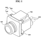
- Fig. 1 is a perspective view of a camera module according to the present exemplary embodiment
- Fig. 2 is an exploded perspective view of a camera module according to the present exemplary embodiment
- Fig. 3 is an exploded perspective view of a part of the camera module according to the present exemplary embodiment
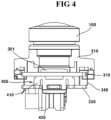
- Fig. 4 is a cross-sectional view of a part of the camera module according to the present exemplary embodiment
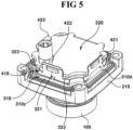
- Fig. 5 is a bottom perspective view of a part of the camera module according to the present exemplary embodiment
- Fig. 6 is an exploded view illustrating a substrate and a support member of the camera module according to the present exemplary embodiment
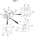
- Fig. 7 is a drawing for explaining a sealing member of the camera module according to the present exemplary embodiment.
- Fig. 8 is a bottom perspective view illustrating a coupling structure between a substrate and a support member of the camera module according to another exemplary embodiment of the present invention
- Fig. 9 is a side view of a coupling structure between the substrate and the support member in Fig. 8 when viewing from the side
- Fig. 10 is a cross-sectional view illustrating a structure wherein the substrate and the support member in Fig. 9 are disposed inside the holder member
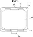
- Fig. 11 is a bottom view illustrating a coupling structure between the substrate and the support member in Fig. 8 wherein the third substrate is omitted
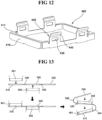
- Fig. 12 is a bottom perspective view illustrating a support member in Fig. 8
- Fig. 13 is a conceptual diagram illustrating a method of coupling a substrate and a supporting member of a camera module according to another exemplary embodiment of the present invention.
- Fig. 14 is a conceptual diagram illustrating a method of assembling a substrate and a supporting member of a camera module according to yet another exemplary embodiment of the present invention.
- the camera module according to the present exemplary embodiment may comprise: a lens module 100; a holder member 200; a substrate unit 300; a supporting member 400; a sealing member 500; a cable 600; and a coupling member 700.
- a lens module 100 may be omitted or changed.
- the sealing member 500, the cable 600, and the coupling member 700 in the camera module according to the present exemplary embodiment may be omitted.
- the lens module 100 may comprise at least one lens.
- the lens module 100 may comprise a plurality of lenses.
- the lens module 100 may comprise a lens and a lens barrel to which the lens is coupled.
- the lens module 100 may be coupled to the holder member 200.
- a first sealing member 510 may be disposed between the lens module 100 and the holder member 200.
- the lens module 100 may be coupled to the through hole 211 of the front body 210 of the holder member 200.
- a light that has passed through the lens module 100 may be incident on an image sensor 301.
- the lens module 100 may be coupled to the holder member 200 using an adhesive. At this time, the adhesive may be epoxy. Epoxies can be cured by ultraviolet (UV) and heat.
- UV ultraviolet
- the optical axis alignment of the image sensor 301 is adjusted in a state where an epoxy is applied between the lens module 100 and the holder member 200, and once the adjustment of the optical axis alignment is completed, the epoxy can be pre-cured through ultraviolet rays and then heated in an oven to progress the final curing.
- the holder member 200 can be coupled to the lens module 100.
- the holder member 200 can accommodate a plurality of substrates 310 and 320 inside thereof.
- the holder member 200 can accommodate the substrate unit 300 inside.
- the holder member 200 may comprise an inner space. At this time, a part of the lens module 100 and the substrate unit 300 may be disposed in the inner space of the holder member 200.
- the holder member 200 together with the lens module 100 can form an appearance of the camera module.
- the holder member 200 may have an approximately hexahedral shape. However, the shape of the holder member 200 is not limited thereto.
- the holder member 200 may comprise a front body 210 and a rear body 220. However, at least any one of the front body 210 or the rear body 220 may be omitted or changed from the holder member 200. That is, the holder member 200 may be integrally formed.
- the front body 210 and the rear body 220 may be coupled to form an inner space.
- a second sealing member 520 may be disposed between the front body 210 and the rear body 220.
- the front body 210 and the rear body 220 may be coupled by the coupling member 700.
- the front body 210 may be coupled to the lens module 100.
- the front body 210 may be coupled to the rear body 220.
- the lower end of the front body 210 may be coupled with the upper end of the rear body 220.
- the front body 210 may be formed of a metallic material.
- the front body 210 may be referred to as "EMI (Electro Magnetic Interference) shield can.”
- the EMI shield can may prevent the electromagnetic interference noise generated from the outside of the holder member 200 from introducing into the inside. Also, the EMI shield can may prevent the electromagnetic interference noise generated inside the holder member 200 from leaking out to the outside.
- the front body 210 may comprise a through hole 211.
- the lens module 100 may be coupled to the through hole 211 of the front body 210.
- the lens module 100 may be inserted into the through hole 211 of the front body 210.
- the through hole 211 may have a circular shape as viewed from above. However, the shape of the through hole 211 is not limited thereto.
- the rear body 220 may be coupled to the front body 210.
- the rear body 220 may be formed to penetrate the cable 600 electrically connected to the plurality of substrates 310 and 320.
- the rear body 220 may comprise a through hole wherein the cable 600 is penetrating through.
- a third sealing member 530 may be disposed between the rear body 220 and the cable 600.
- the rear body 220 may be formed of a metallic material.
- the rear body 220 may be referred to as "EMI (Electro Magnetic Interference) shield can.”
- the EMI shield can prevent the electromagnetic interference noise generated from the outside of the holder member 200 from introducing into the inside. Also, the EMI shield can may prevent the electromagnetic interference noise generated inside the holder member 200 from leaking out to the outside.
- the substrate unit 300 may comprise a plurality of substrates 310 and 320.
- the plurality of substrates 310 and 320 may be accommodated inside the holder member 200.
- the plurality of substrates 310 and 320 may be supported by the support member 400 so as to be spaced apart from each other.
- the plurality of substrates 310 and 320 may be stacked so as to overlap each other along the optical axis direction.
- the substrate unit 300 may comprise a first substrate 310, a second substrate 320, and an FPCB 340. However, at least any one of the first substrate 310, the second substrate 320, and the FPCB 340 may be omitted or changed in the substrate unit 300.
- the first substrate 310 may be a printed circuit board (PCB).
- the first substrate 310 may be coupled to an image sensor 301.
- the image sensor 301 may be disposed on the upper surface of the first substrate 310.
- the first substrate 310 may be spaced apart from the second substrate 320.
- a fence portion 410 may be coupled to the lower surface of the first substrate 310.
- the first substrate 310 may be electrically connected to the second substrate 320.
- the first substrate 310 may have a rectangular plate shape. The area of the upper surface of the first substrate 310 may be larger than the area of the upper surface of the second substrate 320.
- the first substrate 310 may comprise four side surfaces.
- the first substrate 310 may comprise first to fourth side surfaces 310a, 310b, 310c, and 310d.
- the first side surface 310a of the first substrate 310 may be connected to the FPCB 340.
- Curved surfaces may be disposed between the adjacent side surfaces of the first to fourth side surfaces 310a, 310b, 310c, and 310d of the first substrate 310. That is, the first to fourth side surfaces 310a, 310b, 310c, and 310d of the first substrate 310 may be connected by the curved surfaces.
- the second substrate 320 may be a printed circuit board (PCB).
- the second substrate 320 may be disposed on the lower side of the first substrate 310 spaced apart therefrom.
- a support surface 411 of the fence portion 410 may be disposed on the upper surface of the second substrate 320.
- a hook portion 420 may be coupled to the outer circumferential surface of the second substrate 320.
- the second substrate 320 may be electrically connected to the first substrate 310.
- the second substrate 320 may have a rectangular plate shape.
- the area of the upper surface of the second substrate 320 may be smaller than the area of the lower surface of the first substrate 310.
- the second substrate 320 may be smaller than the first substrate 310.
- the second substrate 320 may comprise four side surfaces.
- the second substrate 320 may comprise first to fourth side surfaces 320a, 320b, 320c, and 320d.
- the first side surface 320a of the second substrate 320 may be connected to the FPCB 340.
- the hook portions 420 of the support member 400 may be coupled to the second to fourth side surfaces 320b, 320c, and 320d of the second substrate 320.
- Curved surfaces may be disposed between the adjacent side surfaces of the first to fourth side surfaces 320a, 320b, 320c, and 320d of the second substrate 320. That is, the first to fourth side surfaces 320a, 320b, 320c, and 320d of the second substrate 320 may be connected by the curved surfaces.
- the second substrate 320 may comprise a protrusion 321, a first protruded portion 322, and a second protruded portion 323. However, at least any one of the protrusion 321, the first protruded portion 322, and the second protruded portion 323 may be omitted or changed from the second substrate 320.
- the protrusion 321 may be coupled to a coupling hole 430 of the support member 400.
- the protrusion 321 can be hook-coupled to the hook portion 420 of the support member 400.
- the protrusion 321 may be coupled to the coupling hole 430 formed in the hook portion 420 of the support member 400.
- the protrusion 321 may be inserted into the coupling hole 430 formed in the hook portion 420 of the support member 400.
- the protrusion 321 may protrude outward from the outer circumferential surface of the second substrate 320.
- the protrusion 321 may have a shape corresponding to the coupling hole 430.
- the protrusion 321 may have an approximately rectangular parallelepiped shape.
- the width of the protrusion 321 may be wider than the width of the first protruded portion 322.
- the width of the protrusion 321 may be wider than the width of the second protruded portion 323.
- the protrusion 321 may be formed on the second to fourth side surfaces 320b, 320c, and 320d of the second substrate 320.
- the first protruded portion 322 and the second protruded portion 323 may be formed at both sides of the protrusion 321 on the outer circumferential surface of the second substrate 320 spaced apart from the protrusion 321.
- the first protruded portion 322 and the second protruded portion 323 may be more outwardly protruded than the protrusion 321 on the outer circumferential surface of the second substrate 320.
- the width of each of the first protruded portion 322 and the second protruded portion 323 may be narrower than the width of the protrusion 321.
- the second substrate 320 may further comprise a coupling unit 324 and a connector 325.
- the coupling unit 324 may be disposed on the lower surface of the second substrate 320.
- the coupling unit 324 may be coupled to a coupling portion 610 attached on the cable 600.
- the second substrate 320 can be electrically connected with the cable 600.
- current may be supplied to the second substrate 320 through the coupling unit 324.
- the coupling unit 324 may have a hollow cylindrical shape.
- the coupling pin of the coupling unit 610 formed in the cable 600 may be accommodated inside the hollow space of the coupling unit 324.
- the connector 325 may be disposed on the lower surface of the second substrate 320.
- a connector 620 disposed on the cable 600 may be coupled to the connector 325.
- the second substrate 320 can be electrically connected with the cable 600.
- the second substrate 320 can transmit and receive information (data, control commands, etc.) to and from the external configuration through the connector 325.
- the protrusion 321, the first protruded portion 322, and the second protruded portion 323 are formed on the outer circumferential surface of the second substrate 320.
- a recessed portion formed recessed from the outer circumferential surface of the second substrate 320, and corresponding to a portion between the protrusion 321 and the first protruded portion 322 and the second protruded portion 323, exists.
- the recessed portion may be formed between the projection 321 and the first protruded portion 322.
- the recessed portion may be formed between the projection 321 and the second protruded portion 323.
- the hook portion 420 of the support member 400 may be accommodated in the recessed portion.
- the protrusion 321 may be described as being recessed inwardly with respect to the first protruded portion 322, and the second protruded portion 323.
- the FPCB 340 can electrically connect the plurality of substrates 310 and 320.
- the plurality of substrates 310 and 320 may be a rigid printed circuit board (RPCB), and the FPCB 340 may be a flexible printed circuit board (FPCB). That is, the plurality of substrates 310 and 320 and the FPCB 340 may be formed of rigid flexible PCB (RFPCB).
- the FPCB 340 may electrically connect the first substrate 310 and the second substrate 320.
- the FPCB 340 may be coupled to the first surface 310a of the first substrate 310 and the first surface 320a of the second substrate 320.
- the FPCB 340 may have flexibility at least in part. That is, the FPCB 340 can be bent.
- the FPCB 340 may be bent at least once.
- the FPCB 340 may be bent to form a curved surface at least in part.
- the FPCB 340 may be bent roundly.
- the FPCB 340 may be bent with an angle.
- the support member 400 may be coupled to the plurality of substrates 310 and 320.
- the support member 400 may be coupled to the substrate unit 300.
- the support member 400 may support the plurality of substrates 310 and 320 so as to be spaced apart from each other.
- the support member 400 may be formed of a metal. At this time, the support member 400 can perform the EMI shielding function.
- the support member 400 may have elasticity at least in part. In this case, the support member 400 may be referred to as an "elastic member.”
- the support member 400 may comprise a hook-coupled structure.
- the support member 400 can be used in a three-layer or more substrate stacking structure with a hook-coupled structure.
- the supporting member 400 also facilitates a structure wherein a large number of substrates are required.
- the support member 400 may comprise a fence portion 410, a hook portion 420, a coupling hole 430, and a guide portion 440. At least any one of the fence portion 410, the hook portion 420, the coupling hole 430 and the guide portion 440 may be omitted or changed in the support member 400.
- the fence portion 410 may be disposed between the plurality of substrates 310 and 320.
- the fence portion 410 may be coupled to the first substrate 310.
- the fence portion 410 may be coupled to the first substrate 310 sing surface mounting technology (SMT).
- SMT sing surface mounting technology
- the upper end of the fence portion 410 may be coupled to the lower surface of the first substrate 310.
- the upper end of the fence portion 410 may be coupled to the lower surface of the first substrate 310 by soldering.
- the hook portion 420 may be formed at the lower end of the fence portion 410.
- the fence portion 410 may comprise four side plates.
- the inner space formed by the fence portion 410 may have a rectangular parallelepiped shape.
- the fence portion 410 may be formed in a shape corresponding to the plurality of substrates 310 and 320.
- the fence portion 410 may be coupled to a portion of the lower surface of the first substrate 310 adjacent to the outer circumferential surface. With this structure, it is possible to minimize the
- the fence portion 410 may comprise a support surface 411.
- the support surface 411 can support the second substrate 320.
- the support surface 411 may be in surface contact with the upper surface of the second substrate 320.
- the support surface 411 may be formed by bending at a right angle from the side plate of the fence portion 410.
- the support surface 411 may be formed by bending inward from the side plate of the fence portion 410.
- the support surface 411 may be formed only on a portion of the side plate of the fence portion 410.
- the hook portion 420 may extend from the fence portion 410.
- the hook portion 420 may extend from the lower end of the fence portion 410.
- the hook portion 420 may comprise an extended portion extending from the fence portion and inclined at a predetermined angle from a region where a coupling hole into which a side portion of the second substrate is inserted and an area where the coupling hole is formed.
- the upper end of the fence portion may be engaged with the lower surface of the first substrate by an adhesive material.
- the end of the extended portion may be located further outside than the side surface of the second substrate.
- the support member may not have an area more protruded above the upper surface of the first substrate.
- At least a portion of the hook portion 420 may extend obliquely outwardly as it extends from the fence portion 410 to the distal end side of the hook portion 420.
- a portion extending from the fence portion 410 to the distal end side of the hook portion 420 so as to be inclined outwardly may be referred to as a guide portion 440.
- the hook portion 420 may have elasticity.
- the hook portion 420 may be hook-coupled to the protrusion 321 of the second substrate 320 by elasticity.
- the protrusion 321 of the second substrate 320 may be coupled to the hook portion 420 in a sliding manner from the distal end side of the hook portion 420 towards the fence portion 410.
- the protrusion 321 may be inserted into the coupling hole 430 to maintain a firm coupling.
- the protrusion 321 of the second substrate 320 can be released from the coupling hole 430 formed in the hook portion 420.
- the guide portion 440 can guide the movement of the protrusion 321 so that the protrusion 321 can be coupled with the hook portion 420 in a sliding manner.
- the hook portion 420 is designed to have an overlapping structure with the holder member 200 so that the shaking of the plurality of substrates 310 and 320 during vibration can be prevented.
- the hook portion 420 may comprise a plurality of spaced apart hooks.
- the hook portion 420 may comprise first to third hooks 421, 422, and 423 spaced from each other. However, at least any one of the first to third hooks 421, 422, and 423 may be omitted or changed in the hook portion 420.
- the first hook 421 may be coupled to the second side surface 320b of the second substrate 320.
- the first hook 421 may be coupled with one surface of the second substrate 320.
- the first hook 421 can be in contact with the inner circumferential surface of the holder member 200.
- the third hook 423 disposed on the opposite side of the first hook 421 may also be in contact with the inner circumferential surface of the holder member 200.
- the first hook 421 can be tightly fixed within the holder member 200.
- the first hook 421 may be formed in a shape corresponding to the second and third hooks 422 and 423.
- the second hook 422 may be coupled to the third side surface 320c of the second substrate 320.
- the second hook 422 can be in contact with the inner circumferential surface of the holder member 200.
- the third hook 423 may be coupled to the fourth side surface 320d of the second substrate 320.
- the third hook 423 may be coupled to the other surface of the second substrate 320 that is disposed on the opposite side of the one surface, the surface to which the first hook 421 is coupled, of the second substrate 320.
- the third hook 423 can be in contact with the inner circumferential surface of the holder member 200.
- the FPCB 340 may be coupled to one side surface of the four side surfaces of the second substrate 320 and the hook portion 420 may be coupled to the remaining three side surfaces. That is, the hook portion 420 may be coupled to only three of four side surfaces of the second substrate 320.
- the coupling hole 430 may be formed to penetrate the hook portion 420.
- the coupling hole 430 may be coupled with the protrusion 321 formed on the outer circumferential surface of the second substrate 320.
- the protrusion 321 may be inserted into the coupling hole 430.
- the coupling hole 430 may be formed in a shape corresponding to the protrusion 321.
- the coupling hole 430 may be formed as a groove. That is, the coupling hole 430 may be formed so as to accommodate the protrusion 321 but not to penetrate the hook portion 420.
- the guide portion 440 may be formed on at least a portion of the hook portion 420.
- the guide portion 440 may be formed to extend outwardly from the fence portion 410 toward the distal end of the hook portion 420.
- the guide portion 440 may guide the movement of the second substrate 320 during the process of coupling the second substrate 320 to the support member 400.
- the guide portion 440 may be formed inclined inward as it travels from the distal end of the hook portion 420 towards the fence portion 410. In this case, when the second substrate 320 is pressed from the distal end of the hook portion 420 towards the fence portion 410, the protrusion 321 of the second substrate 320 can be moved up to the coupling holes 430 guided by the guide portion 440.
- the guide portion 440 may function as a grip portion gripped by the user in the process of gripping the second substrate 320 from the support member 400.
- the sealing member 500 can prevent foreign substances such as moisture from entering into the camera module from the outside.
- the sealing member 500 may be disposed between the structures that are separated from each other.
- the sealing member 500 can form a watertight seal between the components that are separated from each other.
- the sealing member 500 can form a hermetic seal between the components that are separated from each other.
- the sealing member 500 may have elasticity at least in part. In this case, the sealing member 500 may be referred to as an "elastic member.”
- the sealing member 500 may comprise a first sealing member 510, a second sealing member 520, and a third sealing member 530. However, at least any one of the first sealing member 510, the second sealing member 520, and the third sealing member 530 in the sealing member 500 may be omitted or changed.
- the first sealing member 510 may be disposed between the lens module 100 and the front body 210.
- the first sealing member 510 may be disposed between the coupling surface of the lens module 100 and the front body 210.
- the first sealing member 510 may be disposed between the lower surface of the lens module 100 and the upper surface of the front body 210.
- the first sealing member 510 may be an O-ring.
- the lens module 100 may comprise a groove in which the first sealing member 510 is accommodated.
- the second sealing member 520 may be disposed between the front body 210 and the rear body 220.
- the second sealing member 520 may be disposed between the coupling surface of the front body 210 and the rear body 220.
- the second sealing member 520 may be disposed between the lower end surface of the front body 210 and the upper end surface of the rear body 220.
- the second sealing member 520 may be a gasket.
- the front body 210 may comprise a groove in which a portion of the second sealing member 520 is accommodated.
- the rear body 220 may comprise a groove in which a portion of the second sealing member 520 is accommodated. At this time, a plurality of grooves may be provided for the rear body 220.
- the third sealing member 530 may be disposed between the rear body 220 and the cable 600.
- the third sealing member 530 may be disposed in a space between the rear body 220 and the cable 600.
- the third sealing member 530 may be a cable seal.
- the cross-section of the third sealing member 530 may be dumbbell-shaped.
- the cable 600 may be electrically connected to the plurality of substrates 310 and 320.
- the cable 600 may be electrically connected to the substrate unit 300.
- the cable 600 may penetrate through the rear body 220.
- the third sealing member 530 may be disposed between the cable 600 and the rear body 220.
- the cable 600 can supply power to the camera module from a power supply unit outside the camera module.
- a plurality of cables 600 may be provided.
- a coupling portion 610 may be coupled to one end of the plurality of cables 600.
- a connector 620 may be coupled to the other end of the plurality of cables 600.
- the coupling portion 610 may be coupled to a coupling portion 324 disposed on the lower surface of the second substrate 320.
- the connector 620 may be coupled to a connector 325 disposed on the lower surface of the second substrate 320.
- the cable 600 can be fixed to the holder member 200 by a cable fixing unit 630.
- the cable fixing unit 630 may comprise a shape corresponding to at least a portion of the cable 600.
- the cable 600 may be disposed between the cable fixing unit 630 and the holder member 200.
- the cable fixing unit 630 can be coupled to the holder member 200 by a coupling member 631. At this time, the coupling member 631 may be a screw.
- the coupling member 700 can couple the rear body 220 and the front body 210 together.
- the coupling member 700 may be a screw. That is, the rear body 220 and the front body 210 can be screw-coupled.
- the number of the coupling members 700 may be four.
- a groove may be formed in the rear body 220 to facilitate the process of rotating the coupling member 700.
- the coupling member 700 may be coupled to the front body 210 penetrating through a hole formed in the rear body 220.
- the substrate unit 300 may comprise a first substrate 310, a second substrate 320, a third substrate 330, and an FPCB 340.
- the first substrate 310, the second substrate 320, the third substrate 330, and the FPCB 340 may be omitted or changed in the substrate unit 300 according to another exemplary embodiment of the present invention. That is, in another exemplary embodiment of the present invention, the number of the substrates 310, 320, and 330 may be increased as compared with the present exemplary embodiment. Accordingly, the number of the support members 400 can also be increased.
- the third substrate 330 may be a printed circuit board (PCB).
- the third substrate 330 may be disposed spaced apart below the second substrate 320.
- a supporting surface 411 of the fence portion 410 of the support member 400 may be disposed on the upper surface of the third substrate 330.
- the hook portion 420 may be coupled to the outer circumferential surface of the third substrate 330.
- the third substrate 330 may be electrically connected to the first and second substrates 310 and 320.
- the third substrate 330 may have a rectangular plate shape.
- the area of the upper surface of the third substrate 330 may be smaller than the area of the lower surface of the second substrate 320.
- the third substrate 330 may be smaller than the second substrate 320.
- the FPCB 340 may electrically connect the second substrate 320 and the third substrate 330. At this time, the FPCB 340 may be separately provided from the one connecting the first substrate 310 and the second substrate 320. That is, a plurality of FPCBs 340 may be provided. At this time, the first FPCB connects the first substrate 310 and the second substrate 320, and the second FPCB connects the second substrate 320 and the third substrate 330. The first FPCB may be disposed on the opposite side of the second FPCB with respect to the plurality of substrates 310, 320, and 330.
- the substrate unit 300 may comprise a first substrate 310, a second substrate 320, a third substrate 330, and a connector 350.
- the substrate unit 300 may comprise at least any one of the first substrate 310, the second substrate 320, the third substrate 330, and the connector 350 may be omitted or changed. That is, in yet another exemplary embodiment of the present invention, the FPCB 340 may be omitted and the connector 350 may be provided when compared with the present exemplary embodiment.
- the connector 350 may electrically connect the first substrate 310 and the second substrate 320.
- the connector 350 may be provided in a pair and disposed on the lower surface of the first substrate 310 and the upper surface of the second substrate 320, respectively.
- the connector 350 may electrically connect the second substrate 320 and the third substrate 330.
- the connector 350 may be provided in a pair and disposed on the lower surface of the second substrate 320 and the upper surface of the third substrate 330, respectively.
- the pair of connectors 350 can electrically conduct the two substrates through mutual coupling.
- connector 350 may be a B2B connector.
- the support member 400 may comprise a first support member 401 and a second support member 402. However, at least any one of the first support member 401 and the second support member 402 in the support member 400 according to another and yet another exemplary embodiment of the present invention may be omitted or changed.
- the first support member 401 may be coupled to the first substrate 310 and the second substrate 320.
- the second support member 402 may be coupled to the second substrate 320 and the third substrate 330.
- the first support member 401 may be coupled to a lower surface of the first substrate 310 and may be hook-coupled to a side surface of the second substrate 320.
- the second support member 402 may be coupled to the lower surface of the second substrate 320 and hook-coupled to the side surface of the third substrate 330.
- the first support member 401 may be formed in a shape corresponding to the second support member 402.
- the size of the first support member 401 may be larger than that of the second support member 402.
- Each of the first support member 401 and the second support member 402 may comprise a fence portion 410, a hook portion 420, a coupling hole 430, and a guide portion 440.
- the inner space formed by the fence portion 410 of the first support member 401 may be larger than the inner space formed by the lower surface of the first substrate 310, and the upper surface of the second substrate 320 the fence portion 410 of the second support member 402, the lower surface of the second substrate 320, and the upper surface of the third substrate 330.
- Fig. 13 is a conceptual diagram illustrating a method of coupling a substrate and a supporting member of a camera module according to another exemplary embodiment of the present invention
- Fig. 14 is a conceptual diagram illustrating a method of assembling a substrate and a supporting member of a camera module according to yet another exemplary embodiment of the present invention.
- FIG. 13 Another embodiment of the present invention shown in FIG. 13 comprises three substrates 310, 320, 330 and two support members 401, 402. At this time, the three substrates 310, 320, and 330 are connected by the FPCB 340.
- the first substrate 310, the FPCB 340, the second substrate 320, the FPCB 340, and the third substrate 330 are sequentially disposed in a line.
- the first support member 401 is mounted on the lower surface of the first substrate 310 (illustrated as the upper surface in FIG. 13 , but illustrated as the lower surface in the state where the substrate unit 300 is accommodated in the holder member 200) using surface mount technology (SMT).
- the second support member 402 is coupled to the lower surface of the second substrate 320 using surface mount technology (SMT).
- the fence portion 410 of the first support member 401 is coupled with the first substrate 310, and the hook portion 420 is spaced apart from the first substrate 310.
- the fence portion 410 of the second support member 402 is coupled to the second substrate 320 and the hook portion 420 is spaced apart from the second substrate 320.
- the FPCB 340 between the first substrate 310 and the second substrate 320 is then folded to couple the second substrate 320 with the hook portion 420 of the first support member 401.
- the guide portion 440 of the first support member 401 guides the second substrate 320 to be more smoothly coupled to the hook portion 420 of the first support member 401. More specifically, the guide portion 440 of the first support member 401 is formed such that the hook portion 420 is widened outward when the second substrate 320 is contacted and pressed by the second substrate 320.
- the protrusion 321 of the second substrate 320 is inserted into the coupling hole 430 of the hook 420 to complete the coupling.
- the hook portion 420 elastically returns and grips the protrusion 321 of the second substrate 320 by accommodating the protrusion 321 inside the coupling hole 430, so that the coupling between the second substrate 320 and the first support member 401 can be maintained firmly.
- the FPCB 340 between the second substrate 320 and the third substrate 330 is folded to couple the third substrate 330 with the hook 420 of the second support member 402.
- the guide portion 440 of the second support member 402 guides the third substrate 330 to the hook portion 420 of the second support member 402 more easily. More specifically, the guide portion 440 of the second support member 402 is formed such that the hook portion 420 is widened outward when the third substrate 330 is contacted and pressed by the third substrate 330.
- the protrusion 321 of the third substrate 330 is inserted into the coupling hole 430 of the hook portion 420 to complete the coupling.
- the hook portion 420 is elastically returned and the protrusion 321 of the third substrate 330 is accommodated in the coupling hole 430, so that the coupling between the third substrate 330 and the second support member 402 can be maintained firmly.
- the user when a user holds the substrate unit 300, the user outwardly pushes the guide portion 440 of the second support member 402, thereby easily removing the third substrate 330 from the second support member 402.
- the second substrate 320 can be easily removed from the first support member 401 by outwardly pressing the guide portion 440 of the first supporting member 401.
- the coupling between the substrates 320 and 330 and the support member 400 can be released just by removing the protrusion 321 from the coupling hole 430.
- FIG. 14 Yet another exemplary embodiment of the present invention illustrated in FIG. 14 comprises three substrates 310, 320, and 330 and two support members 401 and 402. At this time, connectors 350 are disposed on the three substrates 310, 320, and 330.
- a coupling method of a camera module according to yet another exemplary embodiment of the present invention corresponds to a coupling method of a camera module according to another embodiment of the present invention.
- the first to third substrates 310, 320, and 330 are completely separated members that are completely isolated from one other prior to the coupling thereof.
- the first to third substrates 310, 320 and 330 are connected through the FPCB 340.
- the connector 350 disposed on the second substrate 320 and the connector 350 disposed on the first substrate 310 are also coupled together.
- the connector 350 disposed on the third connector 330 and the connector 350 disposed on the second substrate 320 are also coupled together.
- the first to third substrates 310, 320, and 330 are electrically connected to each other through the connector 350 while being fixed spaced apart from each other due to the first and second supporting members 401 and 402.
- the present invention discloses the following items:
Landscapes
- Engineering & Computer Science (AREA)
- Physics & Mathematics (AREA)
- Microelectronics & Electronic Packaging (AREA)
- Multimedia (AREA)
- Signal Processing (AREA)
- General Physics & Mathematics (AREA)
- Optics & Photonics (AREA)
- Mechanical Engineering (AREA)
- Studio Devices (AREA)
- Camera Bodies And Camera Details Or Accessories (AREA)
- Lens Barrels (AREA)
- Structure And Mechanism Of Cameras (AREA)
Abstract
Description
- The present invention relates to a camera module and a vehicle camera.
- In recent years, vehicles equipped with rear cameras have been manufactured and sold in order to secure driver's rear view of the vehicle when a vehicle is moving backward. Meanwhile, in recent years, a structure has been studied wherein a plurality of substrates disposed inside the camera module of a vehicle camera is provided for stacking. However, when a plurality of substrates is fixed with screws, there is a problem in that the screw-coupled area of the substrate becomes a useless area, thereby reducing the component mounting space. In addition, there is a problem in that the manufacturing process time is increased due to the screw coupling work. Also, there is a problem in that warping in the substrate may occur due to an excessive torque at the time of screw tightening.
- An objective of the present exemplary embodiment is to provide a camera module wherein reduction of component mounting space in a stacked structure of a plurality of substrates is minimized.
- Another objective of the present exemplary embodiment is to provide a camera module capable of minimizing process time by using a hook coupling structure that simplifies the process.
- Yet another objective of the present exemplary embodiment is to provide a camera module wherein the warping phenomenon of a substrate is prevented.
- Still another objective of the present exemplary embodiment is to provide a vehicle camera comprising the above described camera module
- As for an exemplary embodiment, a camera module comprises: a lens barrel disposed within a front body and comprising lenses; a first substrate disposed under the front body; a support member with a portion thereof disposed on the bottom surface of the first substrate; and a second substrate disposed under the first substrate and coupled with the support member, wherein the support member comprises a fence portion disposed between the first substrate and the second substrate, and a hook portion extending from the fence portion and having a coupling hole into which some part of a side surface of the second substrate is inserted and an extended portion inclined at a predetermined angle from an area wherein the coupling hole is formed.
- The hook portion may be extended from the lower end of the fence portion, and the coupling hole may be coupled with a protrusion formed on an outer circumferential surface of the second substrate.
- Each of the first substrate and the second substrate may comprise a first side surface, a second side surface, a third side surface, and a fourth side surface, respectively, wherein the first side surface of the first substrate and the first side surface of the second substrate may be connected through FPCB, and wherein the hook portion may comprise a first hook coupled to the second side surface of the second substrate, and a second hook coupled the third side surface of the second substrate, and a third hook coupled to the fourth side surface of the second substrate.
- The upper end of the fence portion may be joined to the lower surface of the first substrate using an adhesive material.
- A plurality of substrates may further comprise a third substrate spaced apart from the lower side of the second substrate, wherein the support member may comprise a first support member coupled to the first substrate and the second substrate, and a second support member coupled to the second substrate and the third substrate, and wherein the inner space formed by a fence portion of the first support member, the lower surface of the first substrate, and the upper surface of the second substrate may be wider than the inner space formed by the fence portion of the second support member, the lower surface of the second substrate, and the upper surface of the third substrate.
- The hook portion may comprise a first hook coupled to one surface of the substrate and a second hook coupled to the other surface of the substrate disposed at the opposite side of the one surface, wherein some portions of the first hook and the second hook may be in contact with the inner circumferential surface of the holder member.
- The protrusion may be protruded outward from the outer circumferential surface of the substrate, wherein a first protruded portion and a second protruded portion being spaced apart from the protrusion and more outwardly protruded than the protrusion at both sides of the protrusion may be formed on the outer circumferential surface of the substrate.
- A first sealing member may be disposed between the lens module and the front body, a second sealing member may be disposed between the front body and the rear body, a third sealing member may be disposed between the rear body and the cable, and the end of the extended portion may be located further outside than the side surface of the second substrate.
- The cross-sectional area of the upper surface of the first substrate may be formed larger than the cross-sectional area of the upper surface of the second substrate, and the supporting member may not have a region more protruded upward than the upper surface of the first substrate.
- As for another exemplary embodiment, a vehicle camera comprises: a lens module comprising at least one lens; a front body accommodating the lens module; a first substrate disposed below the front body; a support member having one end soldered on the lower surface of the first substrate and disposed thereon; a second substrate disposed below the first substrate and coupled to the support member; and a rear body coupled to the front body and accommodating at least a portion of the support member, wherein the support member comprises a fence portion disposed between the first substrate and the second substrate, and a hook portion extending from the fence portion and having a coupling hole into which an outer circumferential portion of the second substrate is inserted, and wherein at least a portion of the hook portion may comprise an extended portion obliquely outwardly extending from the remaining portion except for at least a portion of the fence portion or the hook portion.
- A camera module and a vehicle camera according to the present invention, the reduction in the component mounting space can be minimized despite the stacked structure wherein a plurality of substrates are stacked. Especially, the component mounting space can be increased by 30% as compared with the screw-coupling structure.
- Further, the process time is minimized, since the process is simplified due to the hook coupling structure, and therefore workability and productivity can be improved.
- In addition, the warping phenomenon of the substrates, which may occur during the stacking process of a plurality of substrates, can be prevented.
- In addition, the shaking of the substrate can be prevented when the camera module vibrates.
-
-
Fig. 1 is a perspective view of a camera module according to the present exemplary embodiment. -
Fig. 2 is an exploded perspective view of a camera module according to the present exemplary embodiment. -
Fig. 3 is an exploded perspective view of a part of the camera module according to the present exemplary embodiment. -
Fig. 4 is a cross-sectional view of a part of the camera module according to the present exemplary embodiment. -
Fig. 5 is a bottom perspective view of a part of the camera module according to the present exemplary embodiment. -
Fig. 6 is an exploded view illustrating a substrate and a support member of the camera module according to the present exemplary embodiment. -
Fig. 7 is a drawing for explaining a sealing member of the camera module according to the present exemplary embodiment. -
Fig. 8 is a bottom perspective view illustrating a coupling structure between a substrate and a support member of the camera module according to another exemplary embodiment of the present invention. -
Fig. 9 is a side view of a coupling structure between the substrate and the support member inFig. 8 when viewing from the side. -
Fig. 10 is a cross-sectional view illustrating a structure wherein the substrate and the support member inFig. 9 are disposed inside the holder member. -
Fig. 11 is a bottom view illustrating a coupling structure between the substrate and the support member inFig. 8 wherein the third substrate is omitted. -
Fig. 12 is a bottom perspective view illustrating a support member inFig. 8 . -
Fig. 13 is a conceptual diagram illustrating a method of coupling a substrate and a supporting member of a camera module according to another exemplary embodiment of the present invention. -
Fig. 14 is a conceptual diagram illustrating a method of assembling a substrate and a supporting member of a camera module according to yet another exemplary embodiment of the present invention. - Since the present invention, which will be described below, may apply to various modifications and may have various exemplary embodiments, some specific exemplary embodiments are illustrated in the drawings and will be described in detail in the detailed description.
- This, however, is by no means to restrict the invention to the specific embodiments, it is to be understood as embracing all modifications, equivalents and substitutes included in the spirit and scope of the present invention. If the specific description of the related art in the following description of the present invention that are determined to obscure the gist of the invention, the detailed description thereof is omitted.
- The terms used in the present specification are merely used to describe particular exemplary embodiments, and are not intended to limit the present invention. Expressions in singular forms include plural forms unless the context clearly indicates otherwise. In this application, the terms "comprise," "have," and the like are intended to specify the features, numbers, steps, actions, components, parts, or one that exists combinations thereof described in the specification, but are not intended to preclude the one or more other features, numbers, steps, actions, components, parts, or the presence or possibility of combinations thereof.
- Further, terms such as "first", "second" may be used to separately describe various elements, but the above elements shall not be restricted to the above terms. These terms are only used to distinguish one element from the other.
- Hereinafter, the configuration of a camera module according to the present exemplary embodiment will be described with reference to the drawings. The configurations of a camera module according to another exemplary embodiment and a camera module according to yet another exemplary embodiment of the present invention will also be described with a focus on differences from the configuration of the camera module according to this exemplary embodiment.
-
Fig. 1 is a perspective view of a camera module according to the present exemplary embodiment;Fig. 2 is an exploded perspective view of a camera module according to the present exemplary embodiment;Fig. 3 is an exploded perspective view of a part of the camera module according to the present exemplary embodiment;Fig. 4 is a cross-sectional view of a part of the camera module according to the present exemplary embodiment;Fig. 5 is a bottom perspective view of a part of the camera module according to the present exemplary embodiment;Fig. 6 is an exploded view illustrating a substrate and a support member of the camera module according to the present exemplary embodiment; andFig. 7 is a drawing for explaining a sealing member of the camera module according to the present exemplary embodiment. -
Fig. 8 is a bottom perspective view illustrating a coupling structure between a substrate and a support member of the camera module according to another exemplary embodiment of the present invention;Fig. 9 is a side view of a coupling structure between the substrate and the support member inFig. 8 when viewing from the side;Fig. 10 is a cross-sectional view illustrating a structure wherein the substrate and the support member inFig. 9 are disposed inside the holder member;Fig. 11 is a bottom view illustrating a coupling structure between the substrate and the support member inFig. 8 wherein the third substrate is omitted;Fig. 12 is a bottom perspective view illustrating a support member inFig. 8 ; andFig. 13 is a conceptual diagram illustrating a method of coupling a substrate and a supporting member of a camera module according to another exemplary embodiment of the present invention. -
Fig. 14 is a conceptual diagram illustrating a method of assembling a substrate and a supporting member of a camera module according to yet another exemplary embodiment of the present invention. - The camera module according to the present exemplary embodiment may comprise: a
lens module 100; aholder member 200; asubstrate unit 300; a supportingmember 400; asealing member 500; acable 600; and acoupling member 700. However, in the camera module according to the present exemplary embodiment, at least any one of thelens module 100, theholder member 200, thesubstrate unit 300, the supportingmember 400, the sealingmember 500, thecable 600, and thecoupling member 700 may be omitted or changed. Particularly, the sealingmember 500, thecable 600, and thecoupling member 700 in the camera module according to the present exemplary embodiment may be omitted. - The
lens module 100 may comprise at least one lens. Thelens module 100 may comprise a plurality of lenses. Thelens module 100 may comprise a lens and a lens barrel to which the lens is coupled. Thelens module 100 may be coupled to theholder member 200. Afirst sealing member 510 may be disposed between thelens module 100 and theholder member 200. Thelens module 100 may be coupled to the throughhole 211 of thefront body 210 of theholder member 200. A light that has passed through thelens module 100 may be incident on animage sensor 301. Thelens module 100 may be coupled to theholder member 200 using an adhesive. At this time, the adhesive may be epoxy. Epoxies can be cured by ultraviolet (UV) and heat. As for an example, the optical axis alignment of theimage sensor 301 is adjusted in a state where an epoxy is applied between thelens module 100 and theholder member 200, and once the adjustment of the optical axis alignment is completed, the epoxy can be pre-cured through ultraviolet rays and then heated in an oven to progress the final curing. Theholder member 200 can be coupled to thelens module 100. Theholder member 200 can accommodate a plurality ofsubstrates holder member 200 can accommodate thesubstrate unit 300 inside. Theholder member 200 may comprise an inner space. At this time, a part of thelens module 100 and thesubstrate unit 300 may be disposed in the inner space of theholder member 200. Theholder member 200 together with thelens module 100 can form an appearance of the camera module. Theholder member 200 may have an approximately hexahedral shape. However, the shape of theholder member 200 is not limited thereto. - The
holder member 200 may comprise afront body 210 and arear body 220. However, at least any one of thefront body 210 or therear body 220 may be omitted or changed from theholder member 200. That is, theholder member 200 may be integrally formed. Thefront body 210 and therear body 220 may be coupled to form an inner space. Asecond sealing member 520 may be disposed between thefront body 210 and therear body 220. Thefront body 210 and therear body 220 may be coupled by thecoupling member 700. - The
front body 210 may be coupled to thelens module 100. Thefront body 210 may be coupled to therear body 220. The lower end of thefront body 210 may be coupled with the upper end of therear body 220. Thefront body 210 may be formed of a metallic material. At this time, thefront body 210 may be referred to as "EMI (Electro Magnetic Interference) shield can." The EMI shield can may prevent the electromagnetic interference noise generated from the outside of theholder member 200 from introducing into the inside. Also, the EMI shield can may prevent the electromagnetic interference noise generated inside theholder member 200 from leaking out to the outside. - The
front body 210 may comprise a throughhole 211. Thelens module 100 may be coupled to the throughhole 211 of thefront body 210. Thelens module 100 may be inserted into the throughhole 211 of thefront body 210. The throughhole 211 may have a circular shape as viewed from above. However, the shape of the throughhole 211 is not limited thereto. - The
rear body 220 may be coupled to thefront body 210. Therear body 220 may be formed to penetrate thecable 600 electrically connected to the plurality ofsubstrates rear body 220 may comprise a through hole wherein thecable 600 is penetrating through. Athird sealing member 530 may be disposed between therear body 220 and thecable 600. Therear body 220 may be formed of a metallic material. At this time, therear body 220 may be referred to as "EMI (Electro Magnetic Interference) shield can." The EMI shield can may prevent the electromagnetic interference noise generated from the outside of theholder member 200 from introducing into the inside. Also, the EMI shield can may prevent the electromagnetic interference noise generated inside theholder member 200 from leaking out to the outside. - The
substrate unit 300 may comprise a plurality ofsubstrates substrates holder member 200. The plurality ofsubstrates support member 400 so as to be spaced apart from each other. The plurality ofsubstrates - The
substrate unit 300 may comprise afirst substrate 310, asecond substrate 320, and anFPCB 340. However, at least any one of thefirst substrate 310, thesecond substrate 320, and theFPCB 340 may be omitted or changed in thesubstrate unit 300. - The
first substrate 310 may be a printed circuit board (PCB). Thefirst substrate 310 may be coupled to animage sensor 301. Theimage sensor 301 may be disposed on the upper surface of thefirst substrate 310. Thefirst substrate 310 may be spaced apart from thesecond substrate 320. Afence portion 410 may be coupled to the lower surface of thefirst substrate 310. Thefirst substrate 310 may be electrically connected to thesecond substrate 320. Thefirst substrate 310 may have a rectangular plate shape. The area of the upper surface of thefirst substrate 310 may be larger than the area of the upper surface of thesecond substrate 320. - The
first substrate 310 may comprise four side surfaces. Thefirst substrate 310 may comprise first tofourth side surfaces first side surface 310a of thefirst substrate 310 may be connected to theFPCB 340. Curved surfaces may be disposed between the adjacent side surfaces of the first tofourth side surfaces first substrate 310. That is, the first tofourth side surfaces first substrate 310 may be connected by the curved surfaces. - The
second substrate 320 may be a printed circuit board (PCB). Thesecond substrate 320 may be disposed on the lower side of thefirst substrate 310 spaced apart therefrom. Asupport surface 411 of thefence portion 410 may be disposed on the upper surface of thesecond substrate 320. Ahook portion 420 may be coupled to the outer circumferential surface of thesecond substrate 320. Thesecond substrate 320 may be electrically connected to thefirst substrate 310. Thesecond substrate 320 may have a rectangular plate shape. The area of the upper surface of thesecond substrate 320 may be smaller than the area of the lower surface of thefirst substrate 310. Thesecond substrate 320 may be smaller than thefirst substrate 310. - The
second substrate 320 may comprise four side surfaces. Thesecond substrate 320 may comprise first tofourth side surfaces first side surface 320a of thesecond substrate 320 may be connected to theFPCB 340. Thehook portions 420 of thesupport member 400 may be coupled to the second to fourth side surfaces 320b, 320c, and 320d of thesecond substrate 320. Curved surfaces may be disposed between the adjacent side surfaces of the first tofourth side surfaces second substrate 320. That is, the first tofourth side surfaces second substrate 320 may be connected by the curved surfaces. - The
second substrate 320 may comprise aprotrusion 321, a first protrudedportion 322, and a second protrudedportion 323. However, at least any one of theprotrusion 321, the first protrudedportion 322, and the second protrudedportion 323 may be omitted or changed from thesecond substrate 320. - The
protrusion 321 may be coupled to acoupling hole 430 of thesupport member 400. Theprotrusion 321 can be hook-coupled to thehook portion 420 of thesupport member 400. Theprotrusion 321 may be coupled to thecoupling hole 430 formed in thehook portion 420 of thesupport member 400. Theprotrusion 321 may be inserted into thecoupling hole 430 formed in thehook portion 420 of thesupport member 400. Theprotrusion 321 may protrude outward from the outer circumferential surface of thesecond substrate 320. Theprotrusion 321 may have a shape corresponding to thecoupling hole 430. Theprotrusion 321 may have an approximately rectangular parallelepiped shape. The width of theprotrusion 321 may be wider than the width of the first protrudedportion 322. The width of theprotrusion 321 may be wider than the width of the second protrudedportion 323. Theprotrusion 321 may be formed on the second to fourth side surfaces 320b, 320c, and 320d of thesecond substrate 320. - The first protruded
portion 322 and the second protrudedportion 323 may be formed at both sides of theprotrusion 321 on the outer circumferential surface of thesecond substrate 320 spaced apart from theprotrusion 321. The first protrudedportion 322 and the second protrudedportion 323 may be more outwardly protruded than theprotrusion 321 on the outer circumferential surface of thesecond substrate 320. The width of each of the first protrudedportion 322 and the second protrudedportion 323 may be narrower than the width of theprotrusion 321. - The
second substrate 320 may further comprise acoupling unit 324 and aconnector 325. - The
coupling unit 324 may be disposed on the lower surface of thesecond substrate 320. Thecoupling unit 324 may be coupled to acoupling portion 610 attached on thecable 600. In this way, thesecond substrate 320 can be electrically connected with thecable 600. For example, current may be supplied to thesecond substrate 320 through thecoupling unit 324. Thecoupling unit 324 may have a hollow cylindrical shape. For example, the coupling pin of thecoupling unit 610 formed in thecable 600 may be accommodated inside the hollow space of thecoupling unit 324. - The
connector 325 may be disposed on the lower surface of thesecond substrate 320. Aconnector 620 disposed on thecable 600 may be coupled to theconnector 325. In this way, thesecond substrate 320 can be electrically connected with thecable 600. For example, thesecond substrate 320 can transmit and receive information (data, control commands, etc.) to and from the external configuration through theconnector 325. - In the present exemplary embodiment, it is described that the
protrusion 321, the first protrudedportion 322, and the second protrudedportion 323 are formed on the outer circumferential surface of thesecond substrate 320. However, it may also be described in a way that a recessed portion formed recessed from the outer circumferential surface of thesecond substrate 320, and corresponding to a portion between theprotrusion 321 and the first protrudedportion 322 and the second protrudedportion 323, exists. The recessed portion may be formed between theprojection 321 and the first protrudedportion 322. The recessed portion may be formed between theprojection 321 and the second protrudedportion 323. At this time, a part of thehook portion 420 of thesupport member 400 may be accommodated in the recessed portion. Meanwhile, theprotrusion 321 may be described as being recessed inwardly with respect to the first protrudedportion 322, and the second protrudedportion 323. - The
FPCB 340 can electrically connect the plurality ofsubstrates substrates FPCB 340 may be a flexible printed circuit board (FPCB). That is, the plurality ofsubstrates FPCB 340 may be formed of rigid flexible PCB (RFPCB). TheFPCB 340 may electrically connect thefirst substrate 310 and thesecond substrate 320. TheFPCB 340 may be coupled to thefirst surface 310a of thefirst substrate 310 and thefirst surface 320a of thesecond substrate 320. TheFPCB 340 may have flexibility at least in part. That is, theFPCB 340 can be bent. TheFPCB 340 may be bent at least once. TheFPCB 340 may be bent to form a curved surface at least in part. For example, theFPCB 340 may be bent roundly. Alternatively, theFPCB 340 may be bent with an angle. - The
support member 400 may be coupled to the plurality ofsubstrates support member 400 may be coupled to thesubstrate unit 300. Thesupport member 400 may support the plurality ofsubstrates support member 400 may be formed of a metal. At this time, thesupport member 400 can perform the EMI shielding function. Thesupport member 400 may have elasticity at least in part. In this case, thesupport member 400 may be referred to as an "elastic member." Thesupport member 400 may comprise a hook-coupled structure. Thesupport member 400 can be used in a three-layer or more substrate stacking structure with a hook-coupled structure. The supportingmember 400 also facilitates a structure wherein a large number of substrates are required. - The
support member 400 may comprise afence portion 410, ahook portion 420, acoupling hole 430, and aguide portion 440. At least any one of thefence portion 410, thehook portion 420, thecoupling hole 430 and theguide portion 440 may be omitted or changed in thesupport member 400. - The
fence portion 410 may be disposed between the plurality ofsubstrates fence portion 410 may be coupled to thefirst substrate 310. Thefence portion 410 may be coupled to thefirst substrate 310 sing surface mounting technology (SMT). The upper end of thefence portion 410 may be coupled to the lower surface of thefirst substrate 310. The upper end of thefence portion 410 may be coupled to the lower surface of thefirst substrate 310 by soldering. Thehook portion 420 may be formed at the lower end of thefence portion 410. Thefence portion 410 may comprise four side plates. The inner space formed by thefence portion 410 may have a rectangular parallelepiped shape. Thefence portion 410 may be formed in a shape corresponding to the plurality ofsubstrates fence portion 410 may be coupled to a portion of the lower surface of thefirst substrate 310 adjacent to the outer circumferential surface. With this structure, it is possible to minimize the component mounting space reduction phenomenon on thefirst substrate 310. - The
fence portion 410 may comprise asupport surface 411. Thesupport surface 411 can support thesecond substrate 320. Thesupport surface 411 may be in surface contact with the upper surface of thesecond substrate 320. Thesupport surface 411 may be formed by bending at a right angle from the side plate of thefence portion 410. Thesupport surface 411 may be formed by bending inward from the side plate of thefence portion 410. Thesupport surface 411 may be formed only on a portion of the side plate of thefence portion 410. - The
hook portion 420 may extend from thefence portion 410. Thehook portion 420 may extend from the lower end of thefence portion 410. Thehook portion 420 may comprise an extended portion extending from the fence portion and inclined at a predetermined angle from a region where a coupling hole into which a side portion of the second substrate is inserted and an area where the coupling hole is formed. The upper end of the fence portion may be engaged with the lower surface of the first substrate by an adhesive material. The end of the extended portion may be located further outside than the side surface of the second substrate. The support member may not have an area more protruded above the upper surface of the first substrate. At least a portion of thehook portion 420 may extend obliquely outwardly as it extends from thefence portion 410 to the distal end side of thehook portion 420. At this time, a portion extending from thefence portion 410 to the distal end side of thehook portion 420 so as to be inclined outwardly may be referred to as aguide portion 440. Thehook portion 420 may have elasticity. Thehook portion 420 may be hook-coupled to theprotrusion 321 of thesecond substrate 320 by elasticity. Theprotrusion 321 of thesecond substrate 320 may be coupled to thehook portion 420 in a sliding manner from the distal end side of thehook portion 420 towards thefence portion 410. When the sliding of theprotrusion 321 of thesecond substrate 320 is completed, theprotrusion 321 may be inserted into thecoupling hole 430 to maintain a firm coupling. At this time, when the distal end of thehook portion 420 is outwardly pressed, theprotrusion 321 of thesecond substrate 320 can be released from thecoupling hole 430 formed in thehook portion 420. Theguide portion 440 can guide the movement of theprotrusion 321 so that theprotrusion 321 can be coupled with thehook portion 420 in a sliding manner. Thehook portion 420 is designed to have an overlapping structure with theholder member 200 so that the shaking of the plurality ofsubstrates - The
hook portion 420 may comprise a plurality of spaced apart hooks. Thehook portion 420 may comprise first tothird hooks third hooks hook portion 420. - The
first hook 421 may be coupled to thesecond side surface 320b of thesecond substrate 320. Thefirst hook 421 may be coupled with one surface of thesecond substrate 320. Thefirst hook 421 can be in contact with the inner circumferential surface of theholder member 200. At this time, thethird hook 423 disposed on the opposite side of thefirst hook 421 may also be in contact with the inner circumferential surface of theholder member 200. With such a structure, thefirst hook 421 can be tightly fixed within theholder member 200. Thefirst hook 421 may be formed in a shape corresponding to the second andthird hooks - The
second hook 422 may be coupled to thethird side surface 320c of thesecond substrate 320. Thesecond hook 422 can be in contact with the inner circumferential surface of theholder member 200. - The
third hook 423 may be coupled to thefourth side surface 320d of thesecond substrate 320. Thethird hook 423 may be coupled to the other surface of thesecond substrate 320 that is disposed on the opposite side of the one surface, the surface to which thefirst hook 421 is coupled, of thesecond substrate 320. Thethird hook 423 can be in contact with the inner circumferential surface of theholder member 200. - The
FPCB 340 may be coupled to one side surface of the four side surfaces of thesecond substrate 320 and thehook portion 420 may be coupled to the remaining three side surfaces. That is, thehook portion 420 may be coupled to only three of four side surfaces of thesecond substrate 320. - The
coupling hole 430 may be formed to penetrate thehook portion 420. Thecoupling hole 430 may be coupled with theprotrusion 321 formed on the outer circumferential surface of thesecond substrate 320. Theprotrusion 321 may be inserted into thecoupling hole 430. Thecoupling hole 430 may be formed in a shape corresponding to theprotrusion 321. As an alternative way, thecoupling hole 430 may be formed as a groove. That is, thecoupling hole 430 may be formed so as to accommodate theprotrusion 321 but not to penetrate thehook portion 420. - The
guide portion 440 may be formed on at least a portion of thehook portion 420. Theguide portion 440 may be formed to extend outwardly from thefence portion 410 toward the distal end of thehook portion 420. Theguide portion 440 may guide the movement of thesecond substrate 320 during the process of coupling thesecond substrate 320 to thesupport member 400. Theguide portion 440 may be formed inclined inward as it travels from the distal end of thehook portion 420 towards thefence portion 410. In this case, when thesecond substrate 320 is pressed from the distal end of thehook portion 420 towards thefence portion 410, theprotrusion 321 of thesecond substrate 320 can be moved up to the coupling holes 430 guided by theguide portion 440. Theguide portion 440 may function as a grip portion gripped by the user in the process of gripping thesecond substrate 320 from thesupport member 400. - The sealing
member 500 can prevent foreign substances such as moisture from entering into the camera module from the outside. The sealingmember 500 may be disposed between the structures that are separated from each other. The sealingmember 500 can form a watertight seal between the components that are separated from each other. The sealingmember 500 can form a hermetic seal between the components that are separated from each other. The sealingmember 500 may have elasticity at least in part. In this case, the sealingmember 500 may be referred to as an "elastic member." - The sealing
member 500 may comprise afirst sealing member 510, asecond sealing member 520, and athird sealing member 530. However, at least any one of thefirst sealing member 510, thesecond sealing member 520, and thethird sealing member 530 in the sealingmember 500 may be omitted or changed. - The
first sealing member 510 may be disposed between thelens module 100 and thefront body 210. Thefirst sealing member 510 may be disposed between the coupling surface of thelens module 100 and thefront body 210. Thefirst sealing member 510 may be disposed between the lower surface of thelens module 100 and the upper surface of thefront body 210. Thefirst sealing member 510 may be an O-ring. Thelens module 100 may comprise a groove in which thefirst sealing member 510 is accommodated. - The
second sealing member 520 may be disposed between thefront body 210 and therear body 220. Thesecond sealing member 520 may be disposed between the coupling surface of thefront body 210 and therear body 220. Thesecond sealing member 520 may be disposed between the lower end surface of thefront body 210 and the upper end surface of therear body 220. Thesecond sealing member 520 may be a gasket. Thefront body 210 may comprise a groove in which a portion of thesecond sealing member 520 is accommodated. Therear body 220 may comprise a groove in which a portion of thesecond sealing member 520 is accommodated. At this time, a plurality of grooves may be provided for therear body 220. - The
third sealing member 530 may be disposed between therear body 220 and thecable 600. Thethird sealing member 530 may be disposed in a space between therear body 220 and thecable 600. Thethird sealing member 530 may be a cable seal. The cross-section of thethird sealing member 530 may be dumbbell-shaped. - The
cable 600 may be electrically connected to the plurality ofsubstrates cable 600 may be electrically connected to thesubstrate unit 300. Thecable 600 may penetrate through therear body 220. Thethird sealing member 530 may be disposed between thecable 600 and therear body 220. Thecable 600 can supply power to the camera module from a power supply unit outside the camera module. - A plurality of
cables 600 may be provided. Acoupling portion 610 may be coupled to one end of the plurality ofcables 600. Aconnector 620 may be coupled to the other end of the plurality ofcables 600. Thecoupling portion 610 may be coupled to acoupling portion 324 disposed on the lower surface of thesecond substrate 320. Theconnector 620 may be coupled to aconnector 325 disposed on the lower surface of thesecond substrate 320. - The
cable 600 can be fixed to theholder member 200 by acable fixing unit 630. Thecable fixing unit 630 may comprise a shape corresponding to at least a portion of thecable 600. Thecable 600 may be disposed between thecable fixing unit 630 and theholder member 200. Thecable fixing unit 630 can be coupled to theholder member 200 by acoupling member 631. At this time, thecoupling member 631 may be a screw. - The
coupling member 700 can couple therear body 220 and thefront body 210 together. Thecoupling member 700 may be a screw. That is, therear body 220 and thefront body 210 can be screw-coupled. For example, the number of thecoupling members 700 may be four. A groove may be formed in therear body 220 to facilitate the process of rotating thecoupling member 700. Thecoupling member 700 may be coupled to thefront body 210 penetrating through a hole formed in therear body 220. - In another exemplary embodiment of the present invention, the
substrate unit 300 may comprise afirst substrate 310, asecond substrate 320, athird substrate 330, and anFPCB 340. However, at least any one of thefirst substrate 310, thesecond substrate 320, thethird substrate 330, and theFPCB 340 may be omitted or changed in thesubstrate unit 300 according to another exemplary embodiment of the present invention. That is, in another exemplary embodiment of the present invention, the number of thesubstrates support members 400 can also be increased. - The
third substrate 330 may be a printed circuit board (PCB). Thethird substrate 330 may be disposed spaced apart below thesecond substrate 320. A supportingsurface 411 of thefence portion 410 of thesupport member 400 may be disposed on the upper surface of thethird substrate 330. Thehook portion 420 may be coupled to the outer circumferential surface of thethird substrate 330. Thethird substrate 330 may be electrically connected to the first andsecond substrates third substrate 330 may have a rectangular plate shape. The area of the upper surface of thethird substrate 330 may be smaller than the area of the lower surface of thesecond substrate 320. Thethird substrate 330 may be smaller than thesecond substrate 320. - The
FPCB 340 may electrically connect thesecond substrate 320 and thethird substrate 330. At this time, theFPCB 340 may be separately provided from the one connecting thefirst substrate 310 and thesecond substrate 320. That is, a plurality ofFPCBs 340 may be provided. At this time, the first FPCB connects thefirst substrate 310 and thesecond substrate 320, and the second FPCB connects thesecond substrate 320 and thethird substrate 330. The first FPCB may be disposed on the opposite side of the second FPCB with respect to the plurality ofsubstrates - In yet another exemplary embodiment of the present invention, the
substrate unit 300 may comprise afirst substrate 310, asecond substrate 320, athird substrate 330, and aconnector 350. However, in thesubstrate unit 300 according to yet another exemplary embodiment of the present invention, at least any one of thefirst substrate 310, thesecond substrate 320, thethird substrate 330, and theconnector 350 may be omitted or changed. That is, in yet another exemplary embodiment of the present invention, theFPCB 340 may be omitted and theconnector 350 may be provided when compared with the present exemplary embodiment. - The
connector 350 may electrically connect thefirst substrate 310 and thesecond substrate 320. Theconnector 350 may be provided in a pair and disposed on the lower surface of thefirst substrate 310 and the upper surface of thesecond substrate 320, respectively. Theconnector 350 may electrically connect thesecond substrate 320 and thethird substrate 330. Theconnector 350 may be provided in a pair and disposed on the lower surface of thesecond substrate 320 and the upper surface of thethird substrate 330, respectively. The pair ofconnectors 350 can electrically conduct the two substrates through mutual coupling. As for an example,connector 350 may be a B2B connector. - In another and yet another exemplary embodiments of the present invention, the
support member 400 may comprise afirst support member 401 and asecond support member 402. However, at least any one of thefirst support member 401 and thesecond support member 402 in thesupport member 400 according to another and yet another exemplary embodiment of the present invention may be omitted or changed. - The
first support member 401 may be coupled to thefirst substrate 310 and thesecond substrate 320. Thesecond support member 402 may be coupled to thesecond substrate 320 and thethird substrate 330. Thefirst support member 401 may be coupled to a lower surface of thefirst substrate 310 and may be hook-coupled to a side surface of thesecond substrate 320. Thesecond support member 402 may be coupled to the lower surface of thesecond substrate 320 and hook-coupled to the side surface of thethird substrate 330. Thefirst support member 401 may be formed in a shape corresponding to thesecond support member 402. The size of thefirst support member 401 may be larger than that of thesecond support member 402. Each of thefirst support member 401 and thesecond support member 402 may comprise afence portion 410, ahook portion 420, acoupling hole 430, and aguide portion 440. - The inner space formed by the
fence portion 410 of thefirst support member 401, may be larger than the inner space formed by the lower surface of thefirst substrate 310, and the upper surface of thesecond substrate 320 thefence portion 410 of thesecond support member 402, the lower surface of thesecond substrate 320, and the upper surface of thethird substrate 330. - Hereinafter, a method of combining a camera module according to another and yet another exemplary embodiment of the present invention will be described with reference to the drawings.
-
Fig. 13 is a conceptual diagram illustrating a method of coupling a substrate and a supporting member of a camera module according to another exemplary embodiment of the present invention; andFig. 14 is a conceptual diagram illustrating a method of assembling a substrate and a supporting member of a camera module according to yet another exemplary embodiment of the present invention. - Another embodiment of the present invention shown in
FIG. 13 comprises threesubstrates support members substrates FPCB 340. - The
first substrate 310, theFPCB 340, thesecond substrate 320, theFPCB 340, and thethird substrate 330 are sequentially disposed in a line. At this time, thefirst support member 401 is mounted on the lower surface of the first substrate 310 (illustrated as the upper surface inFIG. 13 , but illustrated as the lower surface in the state where thesubstrate unit 300 is accommodated in the holder member 200) using surface mount technology (SMT). Also, thesecond support member 402 is coupled to the lower surface of thesecond substrate 320 using surface mount technology (SMT). At this time, thefence portion 410 of thefirst support member 401 is coupled with thefirst substrate 310, and thehook portion 420 is spaced apart from thefirst substrate 310. Thefence portion 410 of thesecond support member 402 is coupled to thesecond substrate 320 and thehook portion 420 is spaced apart from thesecond substrate 320. - The
FPCB 340 between thefirst substrate 310 and thesecond substrate 320 is then folded to couple thesecond substrate 320 with thehook portion 420 of thefirst support member 401. At this time, theguide portion 440 of thefirst support member 401 guides thesecond substrate 320 to be more smoothly coupled to thehook portion 420 of thefirst support member 401. More specifically, theguide portion 440 of thefirst support member 401 is formed such that thehook portion 420 is widened outward when thesecond substrate 320 is contacted and pressed by thesecond substrate 320. When thesecond substrate 320 is further pressed, theprotrusion 321 of thesecond substrate 320 is inserted into thecoupling hole 430 of thehook 420 to complete the coupling. Since thehook portion 420 elastically returns and grips theprotrusion 321 of thesecond substrate 320 by accommodating theprotrusion 321 inside thecoupling hole 430, so that the coupling between thesecond substrate 320 and thefirst support member 401 can be maintained firmly. - The
FPCB 340 between thesecond substrate 320 and thethird substrate 330 is folded to couple thethird substrate 330 with thehook 420 of thesecond support member 402. At this time, theguide portion 440 of thesecond support member 402 guides thethird substrate 330 to thehook portion 420 of thesecond support member 402 more easily. More specifically, theguide portion 440 of thesecond support member 402 is formed such that thehook portion 420 is widened outward when thethird substrate 330 is contacted and pressed by thethird substrate 330. When thethird substrate 330 is further pressed, theprotrusion 321 of thethird substrate 330 is inserted into thecoupling hole 430 of thehook portion 420 to complete the coupling. At this time, since thehook portion 420 is elastically returned and theprotrusion 321 of thethird substrate 330 is accommodated in thecoupling hole 430, so that the coupling between thethird substrate 330 and thesecond support member 402 can be maintained firmly. - Meanwhile, when a user holds the
substrate unit 300, the user outwardly pushes theguide portion 440 of thesecond support member 402, thereby easily removing thethird substrate 330 from thesecond support member 402. In addition, thesecond substrate 320 can be easily removed from thefirst support member 401 by outwardly pressing theguide portion 440 of the first supportingmember 401. The coupling between thesubstrates support member 400 can be released just by removing theprotrusion 321 from thecoupling hole 430. - Yet another exemplary embodiment of the present invention illustrated in
FIG. 14 comprises threesubstrates support members connectors 350 are disposed on the threesubstrates - A coupling method of a camera module according to yet another exemplary embodiment of the present invention corresponds to a coupling method of a camera module according to another embodiment of the present invention. However, there is a difference in that in the camera module according to yet another embodiment of the present invention, the first to
third substrates third substrates FPCB 340. - In yet another embodiment of the present invention, during the process of coupling the
second substrate 320 to thefirst support member 401 coupled to thefirst substrate 310, theconnector 350 disposed on thesecond substrate 320 and theconnector 350 disposed on thefirst substrate 310 are also coupled together. In addition, during the process of coupling thethird substrate 330 to thesecond support member 402 coupled to thesecond substrate 320, theconnector 350 disposed on thethird connector 330 and theconnector 350 disposed on thesecond substrate 320 are also coupled together. The first tothird substrates connector 350 while being fixed spaced apart from each other due to the first and second supportingmembers - It should be noted that the exemplary embodiments disclosed in the drawings are merely examples of specific examples for the purpose of understanding, and are not intended to limit the scope of the present invention. It will be apparent to those skilled in the art that other modifications based on the technical spirit of the present invention are possible in addition to the exemplary embodiments disclosed herein.
- The present invention discloses the following items:
- [Item 1] A camera module comprising:
- a lens barrel disposed within a front body and comprising lenses;
- a first substrate with a portion thereof disposed under said front body;
- a support member, with a portion thereof disposed on the bottom surface of said first substrate; and
- a second substrate disposed under said first substrate and coupled with said support member, wherein said support member comprises a fence portion disposed between said first substrate and said second substrate, and a hook portion extending from said fence portion and having a coupling hole into which a portion of a side surface of said second substrate is inserted and an extended portion inclined at a predetermined angle from an area wherein said coupling hole is formed.
- [Item 2] The camera module according to item 1, wherein said hook portion is extended from the lower end of said fence portion, and said coupling hole is coupled with a protrusion formed on an outer circumferential surface of said second substrate.
- [Item 3] The camera module according to item 1, wherein each of said first substrate and said second substrate comprises a first side surface, a second side surface, a third side surface, and a fourth side surface, respectively, wherein said first side surface of said first substrate and said first side surface of said second substrate are connected through FPCB, and wherein said hook portion comprises a first hook coupled to said second side surface of said second substrate, a second hook coupled said third side surface of said second substrate, and a third hook coupled to said fourth side surface of said second substrate.
- [Item 4] The camera module according to item 1, wherein the upper end of said fence portion is coupled to the lower surface of said first substrate using an adhesive material.
- [Item 5] The camera module according to item 1, wherein a third substrate spaced apart from the lower side of said second substrate is further included, wherein said support member comprises a first support member coupled to said first substrate and said second substrate, and a second support member coupled to said second substrate and said third substrate, and wherein the inner space formed by a fence portion of said first support member, the lower surface of said first substrate, and the upper surface of said second substrate is wider than the inner space formed by said fence portion of said second support member, the lower surface of said second substrate, and the upper surface of said third substrate.
- [Item 6] The camera module according to item 1, wherein said hook portion comprises a first hook coupled to one surface of said substrate and a second hook coupled to the other surface of said substrate disposed at the opposite side of the one surface, and wherein some portions of said first hook and said second hook are in contact with the inner circumferential surface of said holder member.
- [Item 7] The camera module according to item 2, wherein said protrusion is protruded outward from the outer circumferential surface of said substrate, and wherein a first protruded portion and a second protruded portion being spaced apart from said protrusion and more outwardly protruded than said protrusion at both sides of said protrusion are formed on the outer circumferential surface of said substrate.
- [Item 8] The camera module according to item 1, wherein a first sealing member is disposed between said lens module and said front body, and a second sealing member is disposed between said front body and said rear body, and a third sealing member is disposed between said rear body and said cable, and wherein the end of said extended portion is located further outside than the side surface of said second substrate.
- [Item 9] The camera module according to item 1, wherein the cross-sectional area of the upper surface of said first substrate is formed larger than the cross-sectional area of the upper surface of said second substrate, and wherein said supporting member does not have a region more protruded upward than the upper surface of said first substrate.
- [Item 10] A vehicle camera comprising:
- a lens module comprising at least one lens;
- a front body accommodating said lens module;
- a first substrate disposed below said front body;
- a support member having one end soldered on the lower surface of said first substrate and disposed thereon;
- a second substrate disposed below said first substrate and coupled to said support member; and
- a rear body coupled to said front body and accommodating at least a portion of said support member, wherein said support member comprises a fence portion disposed between said first substrate and said second substrate, and a hook portion extending from said fence portion and having a coupling hole into which an outer circumferential portion of said second substrate is inserted, and wherein at least a portion of said hook portion comprises an extended portion obliquely outwardly extending from the remaining portion except for at least a portion of said fence portion or said hook portion.
Claims (14)
- A camera module comprising:a front body;a lens barrel disposed within the front body and comprising lenses;a first substrate disposed under the front body;a support member disposed on a bottom surface of the first substrate; anda second substrate disposed under the first substrate and coupled with the support member,wherein the support member comprises a fence portion disposed between the first substrate and the second substrate, and a hook portion extending from the fence portion and having a coupling hole into which a portion of a side surface of the second substrate is inserted and an extended portion inclined at a predetermined angle from an area wherein the coupling hole is formed.
- The camera module according to claim 1, wherein a lower surface of the first substrate is coupled to an upper surface of the fence portion, and an upper surface of the second substrate is coupled to a lower surface of the fence portion.
- The camera module according to claim 1, wherein the hook portion is extended from a lower end of the fence portion, and the coupling hole is coupled with a protrusion formed on an outer circumferential surface of the second substrate.
- The camera module according to claim 1, wherein each of the first substrate and the second substrate comprises a first side surface, a second side surface, a third side surface, and a fourth side surface, respectively, wherein the first side surface of the first substrate and the first side surface of the second substrate are connected through FPCB, and wherein the hook portion comprises a first hook coupled to the second side surface of the second substrate, a second hook coupled the third side surface of the second substrate, and a third hook coupled to the fourth side surface of the second substrate.
- The camera module according to claim 1, wherein an upper end of the fence portion is coupled to the lower surface of the first substrate using an adhesive material.
- The camera module according to claim 1, wherein a third substrate is spaced apart from the lower side of the second substrate wherein the support member comprises a first support member coupled to the first substrate and the second substrate, and a second support member coupled to the second substrate and the third substrate, and wherein the inner space formed by a fence portion of the first support member, the lower surface of the first substrate, and the upper surface of the second substrate is wider than the inner space formed by the fence portion of the second support member, the lower surface of the second substrate, and the upper surface of the third substrate.
- The camera module according to claim 1, wherein a holder member includes a front body and a rear body coupled to the front body to form an inner space such that the first and second substrates are disposed,
wherein the hook portion comprises a first hook coupled to one surface of the substrate and a second hook coupled to the other surface of the substrate disposed at the opposite side of the one surface, and wherein some portions of the first hook and the second hook are in contact with the inner circumferential surface of the holder member. - The camera module according to claim 1, wherein an upper end of the fence portion is soldered to the lower surface of the first substrate.
- The camera module according to claim 1, wherein the cross-sectional area of the upper surface of the first substrate is formed larger than the cross-sectional area of the upper surface of the second substrate, and wherein the supporting member does not have a region more protruded upward than the upper surface of the first substrate.
- The camera module according to claim 1,
wherein a lower surface of the first substrate is coupled to an upper surface of the fence portion, and an upper surface of the second substrate is coupled to a lower surface of the fence portion. - The camera module according to claim 1, wherein the support member includes a guide portion that is inclined outwardly as it extends from the fence portion to a distal end side of the hook portion.
- The camera module according to claim 1, wherein the fence portion is surface mounted on the first substrate (SMT).
- The camera module according to claim 1, wherein the fence portion includes a support surface for supporting the second substrate, and the support surface is in surface contact with the upper surface of the second substrate.
- A vehicle camera comprising the camera module of claim 1.
Applications Claiming Priority (3)
| Application Number | Priority Date | Filing Date | Title |
|---|---|---|---|
| KR1020160113137A KR102645861B1 (en) | 2016-09-02 | 2016-09-02 | Camera module and Camera for vehicle |
| PCT/KR2017/009573 WO2018044108A1 (en) | 2016-09-02 | 2017-08-31 | Camera module and vehicle camera |
| EP17847033.2A EP3509289B1 (en) | 2016-09-02 | 2017-08-31 | Camera module and vehicle camera |
Related Parent Applications (2)
| Application Number | Title | Priority Date | Filing Date |
|---|---|---|---|
| EP17847033.2A Division EP3509289B1 (en) | 2016-09-02 | 2017-08-31 | Camera module and vehicle camera |
| EP17847033.2A Division-Into EP3509289B1 (en) | 2016-09-02 | 2017-08-31 | Camera module and vehicle camera |
Publications (2)
| Publication Number | Publication Date |
|---|---|
| EP4366320A2 true EP4366320A2 (en) | 2024-05-08 |
| EP4366320A3 EP4366320A3 (en) | 2024-07-31 |
Family
ID=61301885
Family Applications (2)
| Application Number | Title | Priority Date | Filing Date |
|---|---|---|---|
| EP17847033.2A Active EP3509289B1 (en) | 2016-09-02 | 2017-08-31 | Camera module and vehicle camera |
| EP24160949.4A Pending EP4366320A3 (en) | 2016-09-02 | 2017-08-31 | Camera module and vehicle camera |
Family Applications Before (1)
| Application Number | Title | Priority Date | Filing Date |
|---|---|---|---|
| EP17847033.2A Active EP3509289B1 (en) | 2016-09-02 | 2017-08-31 | Camera module and vehicle camera |
Country Status (6)
| Country | Link |
|---|---|
| US (3) | US11197369B2 (en) |
| EP (2) | EP3509289B1 (en) |
| JP (4) | JP7069128B2 (en) |
| KR (3) | KR102645861B1 (en) |
| CN (2) | CN109644228B (en) |
| WO (1) | WO2018044108A1 (en) |
Families Citing this family (19)
| Publication number | Priority date | Publication date | Assignee | Title |
|---|---|---|---|---|
| KR102645861B1 (en) | 2016-09-02 | 2024-03-11 | 엘지이노텍 주식회사 | Camera module and Camera for vehicle |
| USD879181S1 (en) * | 2018-07-06 | 2020-03-24 | Actron Technology Corporation | Lens holder of automobile surveillance camera |
| TWI690208B (en) * | 2018-11-01 | 2020-04-01 | 虎山實業股份有限公司 | Photographic installation |
| CN109587382B (en) * | 2018-12-18 | 2024-09-27 | 青岛小鸟看看科技有限公司 | Camera module and depth camera |
| KR102902591B1 (en) * | 2019-11-12 | 2025-12-22 | 엘지이노텍 주식회사 | Camera module |
| DE102019131393A1 (en) * | 2019-11-21 | 2021-05-27 | Connaught Electronics Ltd. | Internally aligned camera and manufacturing process therefor |
| KR102899374B1 (en) * | 2019-12-26 | 2025-12-12 | 엘지이노텍 주식회사 | Camera module and vehicle having the same |
| KR102902854B1 (en) * | 2020-06-12 | 2025-12-23 | 엘지이노텍 주식회사 | Camera modure |
| KR20220000091A (en) * | 2020-06-25 | 2022-01-03 | 엘지이노텍 주식회사 | Camera module |
| KR20220001966A (en) * | 2020-06-30 | 2022-01-06 | 엘지이노텍 주식회사 | Camera module |
| KR102380310B1 (en) * | 2020-08-26 | 2022-03-30 | 삼성전기주식회사 | Camera Module |
| KR20220049200A (en) * | 2020-10-14 | 2022-04-21 | 엘지이노텍 주식회사 | Camera module |
| KR20230006277A (en) * | 2021-07-02 | 2023-01-10 | 엘지이노텍 주식회사 | Camera module |
| KR20230031685A (en) * | 2021-08-27 | 2023-03-07 | 엘지이노텍 주식회사 | Camera module |
| KR20230031693A (en) * | 2021-08-27 | 2023-03-07 | 엘지이노텍 주식회사 | Camera module |
| KR20230072638A (en) * | 2021-11-18 | 2023-05-25 | 엘지이노텍 주식회사 | Camera module |
| KR102767380B1 (en) * | 2022-03-23 | 2025-02-14 | 자화전자(주) | Camera module and manufacturing method of the same |
| CN117692745A (en) * | 2022-08-31 | 2024-03-12 | 信扬科技(佛山)有限公司 | Lens module and electronic device |
| KR20240068502A (en) | 2022-11-10 | 2024-05-17 | 엘지이노텍 주식회사 | Camera modure for vehicle |
Citations (1)
| Publication number | Priority date | Publication date | Assignee | Title |
|---|---|---|---|---|
| WO2016076619A1 (en) * | 2014-11-14 | 2016-05-19 | 엘지이노텍(주) | Camera module for automobile |
Family Cites Families (21)
| Publication number | Priority date | Publication date | Assignee | Title |
|---|---|---|---|---|
| US3066367A (en) * | 1957-05-23 | 1962-12-04 | Bishop & Babcock Corp | Panel mounting fastener |
| US5673172A (en) * | 1996-01-05 | 1997-09-30 | Compaq Computer Corporation | Apparatus for electromagnetic interference and electrostatic discharge shielding of hot plug-connected hard disk drives |
| JP3594439B2 (en) | 1997-02-20 | 2004-12-02 | 松下電器産業株式会社 | camera |
| JP4785421B2 (en) | 2005-05-30 | 2011-10-05 | 市光工業株式会社 | In-vehicle camera structure |
| JP4718243B2 (en) * | 2005-05-30 | 2011-07-06 | 市光工業株式会社 | Connector unit, in-vehicle digital camera, door mirror with in-vehicle camera |
| JP4479643B2 (en) | 2005-10-28 | 2010-06-09 | ソニー株式会社 | Camera module and electronic equipment |
| JP4264556B2 (en) * | 2006-07-28 | 2009-05-20 | ソニー株式会社 | Imaging device |
| KR101449004B1 (en) | 2007-11-21 | 2014-10-08 | 엘지이노텍 주식회사 | Camera module |
| JP5381697B2 (en) | 2009-12-28 | 2014-01-08 | 株式会社リコー | Imaging device |
| CN102611838B (en) * | 2010-03-10 | 2014-11-26 | Smk株式会社 | Waterproofing structure of cable introducing part of vehicle camera module |
| JP2011191328A (en) | 2010-03-11 | 2011-09-29 | Smk Corp | Camera module |
| JP5565117B2 (en) | 2010-06-07 | 2014-08-06 | 株式会社リコー | Imaging device |
| KR101318543B1 (en) | 2011-07-26 | 2013-10-16 | 엘지이노텍 주식회사 | Cable connect structure for camera module |
| KR101428842B1 (en) * | 2011-11-08 | 2014-08-08 | 엘지이노텍 주식회사 | Camera module for Vehicle |
| JP6354305B2 (en) | 2013-11-25 | 2018-07-11 | 株式会社リコー | Grounding component, electronic device, imaging device, and method for producing grounding component |
| CN114785916B (en) | 2014-01-03 | 2024-01-12 | Lg伊诺特有限公司 | Voice coil motor and camera module |
| KR102189443B1 (en) * | 2014-01-29 | 2020-12-11 | 엘지이노텍 주식회사 | Camera |
| KR102255446B1 (en) * | 2014-08-04 | 2021-05-24 | 엘지이노텍 주식회사 | Camera module for vehicle |
| DE102016208547A1 (en) * | 2016-05-18 | 2017-11-23 | Robert Bosch Gmbh | Camera module for a vehicle |
| KR102645861B1 (en) | 2016-09-02 | 2024-03-11 | 엘지이노텍 주식회사 | Camera module and Camera for vehicle |
| WO2019116566A1 (en) | 2017-12-15 | 2019-06-20 | 株式会社ニコン | Optical system, optical equipment, and optical-system manufacturing method |
-
2016
- 2016-09-02 KR KR1020160113137A patent/KR102645861B1/en active Active
-
2017
- 2017-08-31 US US16/329,137 patent/US11197369B2/en active Active
- 2017-08-31 CN CN201780053469.3A patent/CN109644228B/en active Active
- 2017-08-31 JP JP2019511851A patent/JP7069128B2/en active Active
- 2017-08-31 WO PCT/KR2017/009573 patent/WO2018044108A1/en not_active Ceased
- 2017-08-31 CN CN202210438459.4A patent/CN114726992B/en active Active
- 2017-08-31 EP EP17847033.2A patent/EP3509289B1/en active Active
- 2017-08-31 EP EP24160949.4A patent/EP4366320A3/en active Pending
-
2021
- 2021-10-25 US US17/452,193 patent/US12267948B2/en active Active
-
2022
- 2022-05-02 JP JP2022076039A patent/JP7467525B2/en active Active
-
2024
- 2024-03-05 KR KR1020240031605A patent/KR102871098B1/en active Active
- 2024-04-03 JP JP2024060152A patent/JP7771257B2/en active Active
-
2025
- 2025-03-31 US US19/095,954 patent/US20250227838A1/en active Pending
- 2025-10-10 KR KR1020250145915A patent/KR20250153159A/en active Pending
- 2025-11-05 JP JP2025186400A patent/JP2026021498A/en active Pending
Patent Citations (1)
| Publication number | Priority date | Publication date | Assignee | Title |
|---|---|---|---|---|
| WO2016076619A1 (en) * | 2014-11-14 | 2016-05-19 | 엘지이노텍(주) | Camera module for automobile |
Also Published As
| Publication number | Publication date |
|---|---|
| US12267948B2 (en) | 2025-04-01 |
| US20190208626A1 (en) | 2019-07-04 |
| US20250227838A1 (en) | 2025-07-10 |
| JP7069128B2 (en) | 2022-05-17 |
| US20220046791A1 (en) | 2022-02-10 |
| EP4366320A3 (en) | 2024-07-31 |
| EP3509289A4 (en) | 2019-11-13 |
| US11197369B2 (en) | 2021-12-07 |
| KR102871098B1 (en) | 2025-10-15 |
| CN109644228B (en) | 2022-05-17 |
| EP3509289B1 (en) | 2024-04-10 |
| CN114726992A (en) | 2022-07-08 |
| WO2018044108A1 (en) | 2018-03-08 |
| JP2026021498A (en) | 2026-02-10 |
| JP7771257B2 (en) | 2025-11-17 |
| KR102645861B1 (en) | 2024-03-11 |
| KR20250153159A (en) | 2025-10-24 |
| JP2019529975A (en) | 2019-10-17 |
| CN109644228A (en) | 2019-04-16 |
| JP2024088712A (en) | 2024-07-02 |
| CN114726992B (en) | 2024-04-12 |
| JP7467525B2 (en) | 2024-04-15 |
| EP3509289A1 (en) | 2019-07-10 |
| KR20180026146A (en) | 2018-03-12 |
| JP2022115964A (en) | 2022-08-09 |
| KR20240036534A (en) | 2024-03-20 |
Similar Documents
| Publication | Publication Date | Title |
|---|---|---|
| US12267948B2 (en) | Camera module and vehicle camera | |
| KR102708474B1 (en) | Camera module | |
| US12316930B2 (en) | Camera module | |
| US8896749B2 (en) | Lens holder driving device capable of preventing deformation due to heat | |
| US12022173B2 (en) | Internally aligned camera and a manufacturing method thereof | |
| KR102550823B1 (en) | Camera module | |
| KR20160045383A (en) | Camera module using for automobile | |
| KR20160057723A (en) | Camera module using for automobile | |
| WO2021000161A1 (en) | Lens module | |
| KR20220016939A (en) | Lens driving unit and camera module including the same | |
| KR102374763B1 (en) | Camera module | |
| KR102396100B1 (en) | Camera module | |
| US20030171028A1 (en) | Method and apparatus for optical component mounting | |
| US20240305874A1 (en) | Gimbal module and electronic device | |
| KR102374764B1 (en) | Camera module |
Legal Events
| Date | Code | Title | Description |
|---|---|---|---|
| PUAI | Public reference made under article 153(3) epc to a published international application that has entered the european phase |
Free format text: ORIGINAL CODE: 0009012 |
|
| STAA | Information on the status of an ep patent application or granted ep patent |
Free format text: STATUS: THE APPLICATION HAS BEEN PUBLISHED |
|
| AC | Divisional application: reference to earlier application |
Ref document number: 3509289 Country of ref document: EP Kind code of ref document: P |
|
| AK | Designated contracting states |
Kind code of ref document: A2 Designated state(s): AL AT BE BG CH CY CZ DE DK EE ES FI FR GB GR HR HU IE IS IT LI LT LU LV MC MK MT NL NO PL PT RO RS SE SI SK SM TR |
|
| REG | Reference to a national code |
Ref country code: DE Ref legal event code: R079 Free format text: PREVIOUS MAIN CLASS: H04N0023500000 Ipc: G03B0017020000 |
|
| PUAL | Search report despatched |
Free format text: ORIGINAL CODE: 0009013 |
|
| AK | Designated contracting states |
Kind code of ref document: A3 Designated state(s): AL AT BE BG CH CY CZ DE DK EE ES FI FR GB GR HR HU IE IS IT LI LT LU LV MC MK MT NL NO PL PT RO RS SE SI SK SM TR |
|
| RIC1 | Information provided on ipc code assigned before grant |
Ipc: H01R 12/52 20110101ALN20240625BHEP Ipc: H04N 23/50 20230101ALI20240625BHEP Ipc: G03B 30/00 20210101ALI20240625BHEP Ipc: G03B 17/02 20210101AFI20240625BHEP |
|
| STAA | Information on the status of an ep patent application or granted ep patent |
Free format text: STATUS: REQUEST FOR EXAMINATION WAS MADE |
|
| 17P | Request for examination filed |
Effective date: 20250110 |
|
| STAA | Information on the status of an ep patent application or granted ep patent |
Free format text: STATUS: EXAMINATION IS IN PROGRESS |
|
| 17Q | First examination report despatched |
Effective date: 20260318 |