EP4366213A1 - Communications network and methods with enhanced duplex - Google Patents
Communications network and methods with enhanced duplex Download PDFInfo
- Publication number
- EP4366213A1 EP4366213A1 EP23153315.9A EP23153315A EP4366213A1 EP 4366213 A1 EP4366213 A1 EP 4366213A1 EP 23153315 A EP23153315 A EP 23153315A EP 4366213 A1 EP4366213 A1 EP 4366213A1
- Authority
- EP
- European Patent Office
- Prior art keywords
- resource
- downlink
- uplink
- wireless terminal
- sbfd
- Prior art date
- Legal status (The legal status is an assumption and is not a legal conclusion. Google has not performed a legal analysis and makes no representation as to the accuracy of the status listed.)
- Pending
Links
- 238000000034 method Methods 0.000 title claims description 20
- 238000004891 communication Methods 0.000 title description 29
- 238000013507 mapping Methods 0.000 claims abstract description 14
- 230000005540 biological transmission Effects 0.000 description 39
- 238000005516 engineering process Methods 0.000 description 29
- 230000006870 function Effects 0.000 description 13
- 239000000969 carrier Substances 0.000 description 10
- 230000001413 cellular effect Effects 0.000 description 8
- 230000002776 aggregation Effects 0.000 description 7
- 238000004220 aggregation Methods 0.000 description 7
- 230000011664 signaling Effects 0.000 description 7
- 230000012447 hatching Effects 0.000 description 5
- 230000001174 ascending effect Effects 0.000 description 4
- 238000007726 management method Methods 0.000 description 3
- 230000008569 process Effects 0.000 description 3
- 125000004122 cyclic group Chemical group 0.000 description 2
- 238000010586 diagram Methods 0.000 description 2
- 230000007246 mechanism Effects 0.000 description 2
- 238000013468 resource allocation Methods 0.000 description 2
- 230000006399 behavior Effects 0.000 description 1
- 230000009286 beneficial effect Effects 0.000 description 1
- 230000008859 change Effects 0.000 description 1
- 239000000470 constituent Substances 0.000 description 1
- 230000009977 dual effect Effects 0.000 description 1
- 230000000694 effects Effects 0.000 description 1
- 230000007274 generation of a signal involved in cell-cell signaling Effects 0.000 description 1
- 230000007774 longterm Effects 0.000 description 1
- 230000000116 mitigating effect Effects 0.000 description 1
- 230000003287 optical effect Effects 0.000 description 1
- 230000002093 peripheral effect Effects 0.000 description 1
- 229920001690 polydopamine Polymers 0.000 description 1
- 239000004065 semiconductor Substances 0.000 description 1
- 239000000126 substance Substances 0.000 description 1
- 230000007704 transition Effects 0.000 description 1
Images


Classifications
-
- H—ELECTRICITY
- H04—ELECTRIC COMMUNICATION TECHNIQUE
- H04W—WIRELESS COMMUNICATION NETWORKS
- H04W72/00—Local resource management
- H04W72/20—Control channels or signalling for resource management
- H04W72/23—Control channels or signalling for resource management in the downlink direction of a wireless link, i.e. towards a terminal
-
- H—ELECTRICITY
- H04—ELECTRIC COMMUNICATION TECHNIQUE
- H04L—TRANSMISSION OF DIGITAL INFORMATION, e.g. TELEGRAPHIC COMMUNICATION
- H04L5/00—Arrangements affording multiple use of the transmission path
- H04L5/003—Arrangements for allocating sub-channels of the transmission path
-
- H—ELECTRICITY
- H04—ELECTRIC COMMUNICATION TECHNIQUE
- H04W—WIRELESS COMMUNICATION NETWORKS
- H04W72/00—Local resource management
- H04W72/04—Wireless resource allocation
- H04W72/044—Wireless resource allocation based on the type of the allocated resource
- H04W72/0446—Resources in time domain, e.g. slots or frames
-
- H—ELECTRICITY
- H04—ELECTRIC COMMUNICATION TECHNIQUE
- H04L—TRANSMISSION OF DIGITAL INFORMATION, e.g. TELEGRAPHIC COMMUNICATION
- H04L5/00—Arrangements affording multiple use of the transmission path
- H04L5/0001—Arrangements for dividing the transmission path
- H04L5/0003—Two-dimensional division
- H04L5/0005—Time-frequency
-
- H—ELECTRICITY
- H04—ELECTRIC COMMUNICATION TECHNIQUE
- H04L—TRANSMISSION OF DIGITAL INFORMATION, e.g. TELEGRAPHIC COMMUNICATION
- H04L5/00—Arrangements affording multiple use of the transmission path
- H04L5/14—Two-way operation using the same type of signal, i.e. duplex
-
- H—ELECTRICITY
- H04—ELECTRIC COMMUNICATION TECHNIQUE
- H04L—TRANSMISSION OF DIGITAL INFORMATION, e.g. TELEGRAPHIC COMMUNICATION
- H04L5/00—Arrangements affording multiple use of the transmission path
- H04L5/14—Two-way operation using the same type of signal, i.e. duplex
- H04L5/1469—Two-way operation using the same type of signal, i.e. duplex using time-sharing
-
- H—ELECTRICITY
- H04—ELECTRIC COMMUNICATION TECHNIQUE
- H04W—WIRELESS COMMUNICATION NETWORKS
- H04W72/00—Local resource management
- H04W72/04—Wireless resource allocation
- H04W72/044—Wireless resource allocation based on the type of the allocated resource
- H04W72/0453—Resources in frequency domain, e.g. a carrier in FDMA
Definitions
- the technology relates to wireless communications, and particularly to wireless terminals and operations thereof including duplexed operations thereof.
- a radio access network typically resides between wireless devices, such as user equipment (UEs), mobile phones, mobile stations, or any other device having wireless termination, and a core network.
- UEs user equipment
- Example of radio access network types includes the GRAN, GSM radio access network; the GERAN, which includes EDGE packet radio services; UTRAN, the UMTS radio access network; E-UTRAN, which includes Long-Term Evolution; and g-UTRAN, the New Radio (NR).
- a radio access network may comprise one or more access nodes, such as base station nodes, which facilitate wireless communication or otherwise provides an interface between a wireless terminal and a telecommunications system.
- a non-limiting example of a base station can include, depending on radio access technology type, a Node B ("NB"), an enhanced Node B (“eNB”), a home eNB (“HeNB”), a gNB (for a New Radio ["NR”] technology system), or some other similar terminology.
- the 3rd Generation Partnership Project (“3GPP") is a group that, e.g., develops collaboration agreements such as 3GPP standards that aim to define globally applicable technical specifications and technical reports for wireless communication systems.
- 3GPP documents may describe certain aspects of radio access networks.
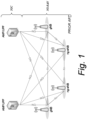
- Overall architecture for a fifth-generation system e.g., the 5G System, also called “NR” or “New Radio”, as well as “NG” or “Next Generation”, is shown in Fig. 1 , and is also described in 3GPP TS 38.300.
- the 5G NR network is comprised of NG RAN, Next Generation Radio Access Network, and 5GC, 5G Core Network.
- NGRAN is comprised of gNBs, e.g., 5G Base stations, and ng-eNBs, i.e., LTE base stations.
- An Xn interface exists between gNB-gNB, between (gNB)-(ng-eNB) and between (ng-eNB)-(ng-eNB).
- the Xn is the network interface between NG-RAN nodes.
- Xn-U stands for Xn User Plane interface
- Xn-C stands for Xn Control Plane interface.
- a NG interface exists between 5GC and the base stations, i.e., gNB & ng-eNB.
- a gNB node provides NR user plane and control plane protocol terminations towards the UE and is connected via the NG interface to the 5GC.
- the 5G NR, New Radio, gNB is connected to Access and Mobility Management Function, AMF, and User Plane Function, UPF, in the 5G Core Network, 5GC.
- Wireless transmissions from a base station in a direction toward a wireless terminal is referred to as being on the "downlink", DL
- transmissions from the wireless terminal in a direction toward the base station is referred to as being on the "uplink", UL.
- the transmissions may occur in a frame or sub-frame structure which may be conceptualized as a two-dimensional grid.
- the grid may be structured to have time slots in a first dimension and frequencies or sub-carriers in a second dimension.
- Time division duplex, TDD occurs when information of the frame or sub-frame is split on a time basis between uplink and downlink.
- TDD operation there may be a mapping or assignment, referred to as a TDD pattern, of time slots to uplink and downlink transmissions.
- Frequency division duplex, FDD operation occurs when information of the frame or sub-frame is split on a frequency or sub-carrier basis between uplink and downlink.
- Uplink coverage is a significant factor for a radio access network.
- TDD time division duplex
- uplink coverage is limited by the TDD pattern since the TDD pattern determines the maximum allowable transmission power for the wireless terminal.
- the TDD pattern is DL heavy, e.g., when a significant number of time slots are utilized for downlink transmission, the UE has less maximum allowable transmission power.
- uplink coverage is limited.
- the network is deployed with a UL heavy TDD pattern, e.g., when a significant number of time slots are utilized for uplink transmission, the network cannot serve enough DL traffic. Therefore, 3GPP takes into consideration operation with simultaneous transmission/reception for base station nodes within frequency resource(s).
- Uplink coverage is a significant factor for cellular network.
- uplink coverage is limited by a ratio R UL/DL of uplink resource and downlink resource.
- R UL/DL the ratio of resource usable for uplink
- Dynamic TDD operation e.g., operation in which there may be a frequent change of the ratio R UL/DL , depending on traffic demand, is a candidate for uplink coverage enhancement.
- the system may increase the amount of uplink resource.
- a wireless terminal communicates across a radio interface with a radio access network.
- the wireless terminal comprises receiver circuitry and processor circuitry.
- the receiver circuitry is configured to receive a downlink signal from the radio access network.
- the processor circuitry is configured to determine a resource assignment (mapping) of the downlink signal to a resource grid of time/frequency radio resources in a SubBand Full Duplex, SBFD, region of the grid in a case that a SBFD uplink, UL, resource set overlaps with a synchronization signal/physical broadcast, SS/PBCH, block in a time domain of the SBFD region.
- the term "telecommunication system” or “communications system” can refer to any network of devices used to transmit information.
- a non-limiting example of a telecommunication system is a cellular network or other wireless communication system.
- the term “cellular network” or “cellular radio access network” can refer to a network distributed over cells, each cell served by at least one fixed-location transceiver, such as a base station.
- a "cell” may be any communication channel. All or a subset of the cell may be adopted by 3GPP as licensed bands, e.g., frequency band, to be used for communication between a base station, such as a Node B, and a UE terminal.
- a cellular network using frequency bands can include configured cells.
- Configured cells can include cells of which a UE terminal is aware and in which it is allowed by a base station to transmit or receive information.
- Examples of cellular radio access networks include E-UTRAN or New Radio, NR, and any successors thereof, e.g., NUTRAN.
- a core network may comprise numerous servers, routers, and other equipment.
- the term "core network” can refer to a device, group of devices, or sub-system in a telecommunication network that provides services to users of the telecommunications network. Examples of services provided by a core network include aggregation, authentication, call switching, service invocation, gateways to other networks, etc.
- a core network may comprise one or more management entities, which may be an Access and Mobility Management Function, AMF.
- a "serving cell” is a cell on which the wireless terminal in idle mode is camped. See, e.g., 3GPP TS 38.304.
- CA/dual connectivity, DC there is only one serving cell comprising the primary cell.
- the term 'serving cells' is used to denote the set of cells comprising of the Special Cell(s) and all secondary cells. See, e.g., 3GPP TS 38.331.
- Fig. 2 shows an example resource grid which illustrates, e.g., enhanced duplex communication.
- the resource grid of Fig. 2 is a two-dimensional grid extending in a time domain (shown by a horizontal axis in Fig. 2 ) and a frequency domain (shown by a vertical axis in Fig. 2 ).
- the time domain of the illustrated resource grid is further divided into regions, including (from left to right):
- the Legacy DL region represents the DL region other than the SBFD region where the base station is not able to perform UL reception.
- Legacy UL region represents the UL region where the base station is not able to perform DL transmission.
- Fig. 2 shows by horizontal hatching the portions of the resource grid which are for downlink transmissions; Fig. 2 shows by vertical hatching the portions of the resource grid which are for uplink transmissions; Fig. 2 shows by both, i.e., superimposed, vertical and horizontal hatching certain resources in the SBFD region that are available for UL transmission.
- the area of region of the grid of Fig. 2 that is illustrated with both vertical and horizontal hatching is also referred to as a SBFD UL resource set or, more simply, the "UL resource set”.
- the time/frequency locations of the regions of the resource grid may be configured in a semi-static manner, and that the DL region and the UL region may be configured by RRC signaling.
- the DL region spans 3 slots and 12 OFDM symbols, and UL region spans 1 slot. The remaining 2 OFDM symbols between the DL region and the UL region are regarded as gap for DL-UL switching.
- the UL resource set is a set of time/frequency resources which may be used for uplink transmission.
- the wireless terminal which communicates with the base station recognize the UL resource set.
- the wireless terminal may determine resource assignment for DL signals such as PDSCH, PDCCH, or CSI-RS.
- the wireless terminal may determine resource assignment for the DL signals such that the DL signals do not overlap with the UL resource set.
- Fig. 3 shows an example of SS/PBCH block on the UL resource set. Since the UL resource set should also be able be used for DL transmission, the SS/PBCH block can be placed within the UL resource set. The situation shown in Fig. 3 implies that the SS/PBCH block disables the UL usage of the UL resource set in OFDM symbols with the SS/PBCH block.
- Fig. 4 Another example is shown in Fig. 4 .
- the SS/PBCH block overlaps with the UL resource set in time domain, but not in frequency domain.
- the wireless terminals of the example embodiments and modes of the technology disclosed herein have the ability and function to recognize an association between the UL resource set and the SS/PBCH block. Thereby, the wireless terminals of the example embodiments and modes appropriately determine resource assignment for DL signals.
- Fig. 5 shows, in generic manner, a communications network in which a wireless terminal determine a resource assignment, e.g., mapping, of a downlink signal to a resource grid of time/frequency radio resources in a SubBand Full Duplex, SBFD, region of the grid in a case that a SBFD uplink, UL, resource set overlaps with a synchronization signal/physical broadcast, SS/PBCH, block in a time domain of the SBFD region.
- the network 20 of Fig. 5 which may be a 5G network, for example, comprises core network 22 connected to at least one radio access network 24.
- the radio access network 24 in turn comprises one or more radio access network (RAN) nodes, such as example base station node 26 which is shown as being connected to the core network 22 by wireline(s) 28.
- the base station node 26 serves at least one cell.
- RAN radio access network
- the radio access network, RAN, 24 typically comprises plural access nodes, one example access nodes 26 being illustrated as a base station node in Fig. 5 .
- access node can refer to any device or group of devices that facilitates wireless communication or otherwise provides an interface between a wireless terminal and a telecommunications system.
- a non-limiting example of a base station can include, in the 3GPP specification, a Node B ("NB"), an enhanced Node B (“eNB”), a home eNB (“HeNB”), a gNB (for a New Radio ["NR”] technology system), a relay node, a mobile relay node, or some other similar terminology.
- Fig. 5 shows the radio access network 24, and base station node 26 through its cell in particular communicating with wireless terminal 30 across a radio or air interface 32.
- the base station node 26 may, and usually does, communicate with plural wireless terminals across the air interface 32. Only one wireless terminal 30 is shown for sake of simplicity, it being understood that other wireless terminals may be provided and may operate in similar manner as the wireless terminal 30 herein illustrated.
- Fig. 5 shows base station node 26 as comprising base station processor circuitry which may comprise one or more base station processors 34, as well as base station transceiver circuitry 36.
- the base station transceiver circuitry 36 may be a transmission and reception point (TRP).
- the transmission and reception point (TRP) 36 may further comprise transmitter circuitry and receiver circuitry.
- the base station processors 34 may comprise frame/message handler/generator 40 which prepares and generates information including user data and messages, e.g., signaling, for transmission over the radio interface 32, as which also processes information received over the radio interface 32.
- the base station processors 34 may also comprise system information block, SIB, generator 42 which serves to generate or at least store system information which is broadcast over the radio interface 32.
- the base station processors 34 may also comprise SBFD configuration memory 44, which stores the configuration of the Sub-Band Full Duplex, SBFD, region. In some example embodiments and modes or scenarios, the SBFD configuration information may be included in the system information generated by system information block, SIB, generator 42.
- the SBFD configuration information may be included in radio resource control, RRC, signaling generated by a radio resource control unit which comprises base station processors 34 and which is included in a RRC message generated by frame/message handler/generator 40.
- RRC radio resource control
- SBFD configuration is comprised of information for configuring the wireless terminal.
- SBFD configuration may include information for configuring some or all of UL subband, DL subband, and SBFD region.
- SBFD configuration may include information indicating SBFD region.
- SBFD configuration may include information indicating TDD pattern.
- SBFD configuration may include information indicating size and/or location of subbands.
- the base station processors 34 may further comprise downlink signal generator 46 and synchronization signal/physical broadcast channel, SS/PBCH, block generator 48.
- the downlink signal generator 46 may generate any appropriate downlink signal or channel, such as Physical Downlink Shared Channel, PDSCH, for example.
- Radio access network (RAN) 22 Communication between radio access network (RAN) 22 and wireless terminal over the radio interface 32 may occur on various layers.
- Layer 1 includes radio layer 1 or the physical layer. Higher layers, e.g., layers higher than Layer 1 may include radio layer 2 and radio resource control layer 3.
- the layer 1 communication may occur by utilization of "resources". Reference to a “resource” herein means “radio resource” unless otherwise clear from the context that another meaning is intended.
- a radio resource is a time-frequency unit that can carry information across a radio interface, e.g., either signal information or data information.
- An example of a radio resource may occur in the context of a "frame" of information that is typically formatted and prepared, e.g., by a node.
- a frame which may have both downlink portion(s) and uplink portion(s), is communicated between the base station and the wireless terminal.
- Each frame may comprise plural subframes. For example, in the time domain, a 10-millisecond frame consists of ten one millisecond subframes.
- a subframe is divided into one or more slots (so that there are thus a multiple of 10 slots in a frame).
- the transmitted signal in each slot is described by a resource grid comprised of resource elements (RE).
- Each column of the two-dimensional grid represents a symbol (e.g., an OFDM symbol) from node to wireless terminal.
- Each row of the grid represents a subcarrier.
- a resource element, RE is the smallest time-frequency unit for transmission in the subframe. That is, one symbol on one sub-carrier in the sub-frame comprises a resource element (RE) which is uniquely defined by an index pair ( k, l ) in a slot (where k and l are the indices in the frequency and time domain, respectively). In other words, one symbol on one sub-carrier is a resource element (RE). Each symbol comprises a number of sub-carriers in the frequency domain, depending on the channel bandwidth and configuration.
- the - frequency resource supported by the standard today is a set of plural subcarriers in one OFDM symbols (e.g., plural resource elements (RE)) and is called a resource block (RB).
- a resource block may comprise, for example, 12 resource elements, i.e., 12 subcarriers and 7 symbols.
- a frame consists of 10 millisecond, milli-second, duration.
- a frame consists of 10 subframes with each having 1ms duration like LTE.
- Each subframe consists of 2 ⁇ slots.
- Each slot can have either 14 (normal CP) or 12 (extended CP) OFDM symbols.
- a Slot is typical unit for transmission used by scheduling mechanism.
- NR allows transmission to start at any OFDM symbol and to last only as many symbols as required for communication. This is known as "mini-slot" transmission. This facilitates very low latency for critical data communication as well as minimizes interference to other RF links.
- a mini-slot helps to achieve lower latency in 5G NR architecture. Unlike slot, mini-slots are not tied to the frame structure. It helps in puncturing the existing frame without waiting to be scheduled. See, for example, https://www.rfwireless-world.com/5G/5G-NR-Mini-Slot.html, which is incorporated herein by reference.
- serving cell frequency resource refers to a plurality of radio resources which may radio resources comprising layer 1 communications between base station node 26 and wireless terminal 30.
- serving cell frequency resource encompasses and includes a frame, having examples described above, or a resource grid, or plural carriers, for example.
- the serving cell frequency resource typically includes a control region. In New Radio, the control region can be placed in any region in time/frequency domain, whereas in some earlier LTE versions the control region should be preferably located in the beginning of a subframe.
- the control region may include scheduling information.
- An example of scheduling information is a PDCCH with a downlink control information, DCI format.
- the scheduling information may describe or reference other portions of the serving cell frequency resource.
- the other portion of serving cell frequency resource that may be described or referenced by the scheduling information may be one or more physical channels.
- An example physical channel is the physical downlink shared channel, PDSCH.
- the base station node 26 may be structured essentially as shown in Fig. 5 or may be a node having architecture such as split architecture comprising a central unit and one or more distributed units that comprise mobile termination (MT).
- the base station processor(s) may include one or more TRPs.
- wireless terminal can refer to any electronic device used to communicate voice and/or data via a telecommunications system, such as (but not limited to) a cellular network.
- a telecommunications system such as (but not limited to) a cellular network.
- Other terminology used to refer to wireless terminals and non-limiting examples of such devices can include user equipment terminal, UE, mobile station, mobile device, access terminal, subscriber station, mobile terminal, remote station, user terminal, terminal, subscriber unit, cellular phones, smart phones, personal digital assistants ("PDAs”), laptop computers, tablets, netbooks, e-readers, wireless modems, etc.
- PDAs personal digital assistants
- Fig. 5 also shows various example constituent components and functionalities of wireless terminal 30.
- Fig. 5 wireless terminal 30 as comprising terminal transceiver circuitry 50.
- the transceiver circuitry 50 in turn may comprise terminal transmitter circuitry 52 and terminal receiver circuitry 54.
- the terminal transceiver circuitry 50 may include antenna(e) for the wireless transmission.
- Terminal transmitter circuitry 52 may include, e.g., amplifier(s), modulation circuitry and other conventional transmission equipment.
- Terminal receiver circuitry 54 may comprise, e.g., amplifiers, demodulation circuitry, and other conventional receiver equipment.
- the terminal receiver circuitry 54 is, in the generic example embodiment and mode of Fig. 5 , configured to receive, over the radio interface, e.g., information concerning scheduling of a virtual resource block for a downlink channel such as the Physical Downlink Shared Channel, PDSCH. In some example embodiments and modes terminal receiver circuitry 54 may also receive information concerning an alternate resource allocation technique and a physical resource block corresponding to the virtual resource block of the downlink channel.
- wireless terminal 30 also comprising wireless terminal processor circuitry, e.g., one or more wireless terminal processor(s) 60.
- the wireless terminal 30, e.g., wireless terminal processor(s) 60 may comprise resource manager 62.
- the resource manager 62 may also be referred to or function as a frame/message generator/handler.
- the wireless terminal processor(s) 60 may comprise resource assignment controller 66.
- the wireless terminal processor(s) 60 may simply receive information from base station node 26 that will enable wireless terminal 30 to know the location of the physical downlink channel of interest.
- the wireless terminal 30 may receive, in a message or signal, an indication of the location of the physical downlink channel in the frame after the base station node 26 has performed a check and possibly overridden the mapping of the default mapping scheme.
- resource assignment controller 66 of the wireless terminal 30 of Fig. 5 determine a resource assignment, e.g., a mapping, of the downlink signal to a resource grid of time/frequency radio resources in a SubBand Full Duplex, SBFD, region of the grid in a case that a SBFD uplink, UL, resource set overlaps with a synchronization signal/physical broadcast, SS/PBCH, block in a time domain of the SBFD region.
- the downlink signal may be one of a physical downlink shared channel, PDSCH; a physical downlink control channel, PDCCH; and a channel state information-reference signal, CSI-RS.
- Fig. 6 shows example acts or steps which may optionally be performed by the wireless terminal 30 in a generic mode of Fig. 5 .
- Act 6-1 comprises the wireless terminal 30 receiving a downlink signal across the radio interface.
- Act 6-2 comprises the wireless terminal 30, and resource assignment controller 66 for example, determining a resource assignment (mapping) of the downlink signal to a resource grid of time/frequency radio resources in a SubBand Full Duplex, SBFD, region of the grid in a case that a SBFD uplink, UL, resource set overlaps with a synchronization signal/physical broadcast, SS/PBCH, block in a time domain of the SBFD region.
- SBFD SubBand Full Duplex
- the wireless terminal 30 knows the location of the synchronization signal/physical broadcast, SS/PBCH, block because the base station notifies the configuration of the location via RRC signaling.
- Fig. 7 shows an example of resource assignment for a wireless terminal on an enhanced duplex configuration.
- resource assignment of a PDSCH is overlapped with the UL resource set.
- the gNB could schedule uplink transmission for another wireless terminal, and therefore, the PDSCH should be transmitted by avoiding the resource in the UL resource set.
- the wireless terminal is supposed to recognize the UL resource set as unavailable for the PDSCH.
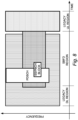
- Fig. 8 is another example scenario of resource assignment for a wireless terminal on an enhanced duplex configuration.
- resource assignment of a PDSCH is overlapped with the SS/PBCH block as well as the UL resource set.
- the gNB would not use the UL resource set in symbols with the SS/PBCH block for scheduling UL transmission. Therefore, the PDSCH can be mapped to the UL resource set in the symbols with the SS/PBCH block. Accordingly, the UL resource set in symbols without SS/PBCH, i.e., the symbols which do not overlap with SS/PBCH, would be still available for UL transmission, whereas the symbols within the SS/PBCH block would not be available for UL transmission.
- the resource assignment controller 66 may make a determination that symbols in the SubBand Full Duplex, SBFD, region in which both the SS/PBCH block and the downlink signal overlap in both the time domain and a frequency domain can be used for the downlink signal.
- resource assignment controller 66 may make a determination that symbols SBFD uplink, UL, resource set which do not overlap with the SS/PBCH block in the time domain can be used for an uplink transmission.
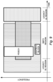
- Fig. 9 is another example scenario of resource assignment for a wireless terminal on an enhanced duplex configuration.
- resource assignment of a PDSCH is overlapped with the UL resource set, and the resource assignment of the PDSCH is overlapped with the SS/PBCH block in time domain.
- the gNB may or may not use the UL resource set in symbols with the SS/PBCH block for scheduling UL transmission.
- the gNB may provide indication, e.g., by radio resource control, RRC, signaling or DCI, indicating whether or not for the wireless terminal to recognize the UL resource set in symbols with the SS/PBCH block as available.
- the wireless terminal 30, e.g., resource assignment controller 66 makes a selective determination to map the downlink signal to symbols in the SubBand Full Duplex, SBFD, region, which overlap in the time domain with the SBFD UL resource set and the SS/PBCH block, in a case that the SS/PBCH block does not overlap in a frequency domain with the downlink signal.
- the determination of the Fig. 9 scenario may be based on an indication received from the radio access network.
- the indication may comprise the indication comprises radio resource control, RRC, signalling, or DCI.
- the base station knows the configuration of the wireless terminal, including the PDSCH resource assignment, the UL resource set configuration, and the SS/PBCH block configuration. The base station knows the exact UE behavior by considering the configuration of the wireless terminal.
- wireless terminal 30, e.g., resource assignment controller 66 is configured to perform various functions such as: (1) manage an uplink, UL, resource set, the UL resource set comprising a SubBand Full Duplex, SBFD, region of a resource grid defined by time/frequency resources; (2) determine resource assignment for the downlink link signal in consideration of the UL resource; and (3) to disable the UL resource set in symbols of the SBFD region which overlap in a time domain with a synchronization signal/physical broadcast, SS/PBCH, block.
- functions such as: (1) manage an uplink, UL, resource set, the UL resource set comprising a SubBand Full Duplex, SBFD, region of a resource grid defined by time/frequency resources; (2) determine resource assignment for the downlink link signal in consideration of the UL resource; and (3) to disable the UL resource set in symbols of the SBFD region which overlap in a time domain with a synchronization signal/physical broadcast, SS/PBCH, block.
- the wireless terminal 30 comprises control circuitry configured to manage UL resource set defined by time/frequency resource; resource determination circuitry configured to determine resource assignment for a PDSCH based on the UL resource set if the UL resource set is enabled.
- the control circuitry is further configured to disable the UL resource set in symbols which overlaps with a SS/PBCH block.
- “enable” means that the wireless terminal determines resource assignment for any downlink transmission by taking the UL resource set into account. For example, if assigned resources for a PDSCH is overlapping partially with the UL resource set, the wireless terminal determines actual resource assignment as the resource excluding the UL resource set.
- “Disable” means that the wireless terminal determines resource assignment for any downlink transmission by NOT taking the UL resource set into account. For example, even if assigned resources for a PDSCH is overlapping partially with the UL resource set, the wireless terminal determines actual resource as is. It means that the wireless terminal receives signal for the PDSCH even in the UL resource set.
- an efficient downlink resource allocation mechanism is provided by example embodiments and modes of the technology disclosed herein, which is particularly but not exclusively beneficial for SBFD.
- At least OFDM Orthogonal Frequency Division Multiplex
- An OFDM symbol is a unit of time domain of the OFDM.
- the OFDM symbol includes at least one or more subcarriers. Contents in an OFDM symbol are converted to a time-continuous signal in baseband signal generation.
- CP-OFDM Cyclic Prefix-Orthogonal Frequency Division Multiplex
- DFT-s-OFDM Discrete Fourier Transform-spread-Orthogonal Frequency Division Multiplex
- DFT-s-OFDM may be given by applying transform precoding to CP-OFDM.
- CP-OFDM is OFDM using CP (Cyclic Prefix).
- the OFDM symbol may be a designation including a CP added to the OFDM symbol. That is, an OFDM symbol may be configured to include the OFDM symbol and a CP added to the OFDM symbol.
- a serving cell may be configured to include at least one downlink component carrier (downlink carrier) and/or one uplink component carrier (uplink carrier).
- a serving cell may be configured to include at least two or more downlink component carriers and/or two or more uplink component carriers.
- a downlink component carrier and an uplink component carrier are also referred to as component carriers (carriers).
- one resource grid may be provided for one component carrier.
- one resource grid may be provided for combination of a component carrier and a subcarrier-spacing configuration u.
- a subcarrier-spacing configuration u is also referred to as numerology.
- a resource grid includes N size, u grid, x N RB sc subcarriers.
- the resource grid starts from a common resource block with index N start, u grid.
- the common resource block with the index N start, u grid is also referred to as a reference point of the resource grid.
- the resource grid includes N subframe, u symb OFDM symbols.
- the subscript x indicates the transmission direction, and indicates either downlink or uplink.
- One resource grid is provided for an antenna port p, a subcarrier-spacing configuration u, and a transmission direction x.
- the number of slots included in a subframe and indexes are provided.
- slot index n u s is provided in ascending order with an integer value ranging from 0 to N subframe,u slot -1 in a subframe.
- the number of slots included in a radio frame and indexes of slots included in the radio frame is provided.
- the slot index n u s, f is provided in ascending order with an integer value ranging from 0 to N frame,u slot -1 in the radio frame.
- a resource block (RB: Resource Block) includes N RB sc consecutive subcarriers.
- Common resource blocks for a subcarrier-spacing configuration u are indexed in ascending order from 0 in the frequency domain in a common resource block-set.
- the common resource block with index 0 for the subcarrier-spacing configuration u includes (or collides with, matches) the point 3000.
- Physical resource blocks for a subcarrier-spacing configuration u are indexed in ascending order from 0 in the frequency domain in a BWP.
- the N start,u BWP,i indicates the reference point of BWP with index i.
- a BWP is defined as a subset of common resource blocks included in the resource grid.
- the BWP includes N size, u BWP,i common resource blocks starting from the reference points N start,u BWP,i .
- a BWP for the downlink component carrier is also referred to as a downlink BWP.
- a BWP for the uplink component carrier is also referred to as an uplink BWP.
- One or more downlink BWPs may be configured for each serving cell (or each downlink component carrier).
- One or more uplink BWPs may be configured for each serving cell (or each uplink component carrier).
- one downlink BWP may be set as an active downlink BWP (or one downlink BWP may be activated).
- one uplink BWP may be set as an active uplink BWP (or one uplink BWP may be activated).
- a PDSCH, a PDCCH, and a CSI-RS may be received in the active downlink BWP.
- the wireless terminal may receive the PDSCH, the PDCCH, and the CSI-RS in the active downlink BWP.
- a PUCCH and a PUSCH may be sent on the active uplink BWP.
- the wireless terminal may transmit the PUCCH and the PUSCH in the active uplink BWP.
- the active downlink BWP and the active uplink BWP are also referred to as active BWP.
- the PDSCH, the PDCCH, and the CSI-RS may not be received in downlink BWPs (inactive downlink BWPs) other than the active downlink BWP.
- the wireless terminal may not receive the PDSCH, the PDCCH, and the CSI-RS in the downlink BWPs which are other than the active downlink BWP.
- the PUCCH and the PUSCH do not need to be transmitted in uplink BWPs (inactive uplink BWPs) other than the active uplink BWP.
- the wireless terminal may not transmit the PUCCH and the PUSCH in the uplink BWPs which is other than the active uplink BWP.
- the inactive downlink BWP and the inactive uplink BWP are also referred to as inactive BWP.
- Downlink BWP switching deactivates an active downlink BWP and activates one of inactive downlink BWPs.
- the downlink BWP switching may be controlled by a BWP field included in downlink control information.
- the downlink BWP switching may be controlled based on higher-layer parameters.
- Uplink BWP switching is used to deactivate an active uplink BWP and activate any inactive uplink BWP.
- Uplink BWP switching may be controlled by a BWP field included in downlink control information.
- the uplink BWP switching may be controlled based on higher-layer parameters.
- two or more downlink BWPs may not be set as active downlink BWPs.
- one downlink BWP may be active at a certain time.
- two or more uplink BWPs may not be set as active uplink BWPs.
- one uplink BWP may be active at a certain time.
- Carrier aggregation may be communication using a plurality of aggregated serving cells. Carrier aggregation may be communication using a plurality of aggregated component carriers. Carrier aggregation may be communication using a plurality of aggregated downlink component carriers. Carrier aggregation may be communication using a plurality of aggregated uplink component carriers.
- a downlink physical channel may correspond to a set of resource elements that carry information originating from the higher-layer and/or downlink control information.
- the downlink physical channel may be a physical channel used in the downlink component carrier.
- the base station transmits the downlink physical channel.
- the wireless terminal receives the downlink physical channel.
- PBCH Physical Broadcast Channel
- PDCCH Physical Downlink Control Channel
- PDSCH Physical Downlink Shared Channel
- a PDCCH is used to transmit downlink control information (DCI).
- DCI downlink control information
- a PDCCH is transmitted to deliver downlink control information.
- Downlink control information is mapped to a PDCCH.
- the terminal device 1 receives a PDCCH in which downlink control information is mapped.
- the base station transmits the PDCCH in which the downlink control information is mapped.
- a wireless terminal typically determines on what resources to receive a physical downlink shared channel, PDSCH, according to a procedure that involves the following steps:
- DCI format Downlink control information format
- DCI format is collection of information fields. "DCI format” may be used interchangeably with the phrase "DCI”.
- DCI format is a generic name for DCI format 0_0, DCI format 0_1, DCI format 1_0, and DCI format 1_1.
- Uplink DCI format is a generic name at least including the DCI format 0_0 and the DCI format 0_1.
- Downlink DCI format is a generic name at least including the DCI format 1_0 and the DCI format 1_1.
- the term "and/or” should be interpreted to mean one or more items.
- the phrase “A, B and/or C” should be interpreted to mean any of: only A, only B, only C, A and B (but not C), B and C (but not A), A and C (but not B), or all of A, B, and C.
- the phrase "at least one of” should be interpreted to mean one or more items.
- the phrase "at least one of A, B and C” or the phrase “at least one of A, B or C” should be interpreted to mean any of: only A, only B, only C, A and B (but not C), B and C (but not A), A and C (but not B), or all of A, B, and C.
- the phrase “one or more of” should be interpreted to mean one or more items.
- the phrase “one or more of A, B and C” or the phrase “one or more of A, B or C” should be interpreted to mean any of: only A, only B, only C, A and B (but not C), B and C (but not A), A and C (but not B), or all of A, B, and C
- Certain units and functionalities of the systems 20 may be implemented by electronic machinery.
- electronic machinery may refer to the processor circuitry described herein, such as terminal processor circuitry 60 and base station processor 34 and suffixed versions thereof.
- processor circuitry is not limited to mean one processor, but may include plural processors, with the plural processors operating at one or more sites.
- server is not confined to one server unit but may encompasses plural servers and/or other electronic equipment and may be co-located at one site or distributed to different sites.
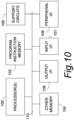
- processor circuitry shows an example of electronic machinery, e.g., processor circuitry, as comprising one or more processors 100, program instruction memory 102; other memory 104 (e.g., RAM, cache, etc.); input/output interfaces 106 and 107, peripheral interfaces 108; support circuits 109; and busses 110 for communication between the aforementioned units.
- the processor(s) 100 may comprise the processor circuitries described herein, for example, terminal processor circuitry 60 and node processor circuitry 34, or any processor(s) of a network entity of the core network and suffixed versions thereof.
- a memory or register described herein may be depicted by memory 104, or any computer-readable medium, may be one or more of readily available memory such as random access memory (RAM), read only memory (ROM), floppy disk, hard disk, flash memory or any other form of digital storage, local or remote, and is preferably of non-volatile nature, as and such may comprise memory.
- RAM random access memory
- ROM read only memory
- floppy disk hard disk
- flash memory any other form of digital storage, local or remote
- the support circuits 109 are coupled to the processors 100 for supporting the processor in a conventional manner. These circuits include cache, power supplies, clock circuits, input/output circuitry and subsystems, and the like.
- Configured may relate to the capacity of a device whether the device is in an operational or non-operational state. Configured may also refer to specific settings in a device that effect the operational characteristics of the device whether the device is in an operational or nonoperational state. In other words, the hardware, software, firmware, registers, memory values, and/or the like may be "configured” within a device, whether the device is in an operational or nonoperational state, to provide the device with specific characteristics.
- An interface may be a hardware interface, a firmware Interface, a software interface, and/or a combination thereof.
- the hardware interface may include connectors, wires, electronic devices such as drivers, amplifiers, and/or the like.
- a software interface may include code stored in a memory device to implement protocol(s), protocol layers, communication drivers, device drivers, combinations thereof, and/or the like.
- a firmware interface may include a combination of embedded hardware and code stored in and/or in communication with a memory device to implement connections, electronic device operations, protocol(s), protocol layers, communication drivers, device drivers, hardware operations, combinations thereof, and/or the like.
- the processes and methods of the disclosed embodiments may be discussed as being implemented as a software routine, some of the method steps that are disclosed therein may be performed in hardware as well as by a processor running software. As such, the embodiments may be implemented in software as executed upon a computer system, in hardware as an application specific integrated circuit or other type of hardware implementation, or a combination of software and hardware.
- the software routines of the disclosed embodiments are capable of being executed on any computer operating system, and is capable of being performed using any CPU architecture.
- the functional blocks may include or encompass, without limitation, digital signal processor (DSP) hardware, reduced instruction set processor, hardware (e.g., digital or analog) circuitry including but not limited to application specific integrated circuit(s) [ASIC], and/or field programmable gate array(s) (FPGA(s)), and (where appropriate) state machines capable of performing such functions.
- DSP digital signal processor
- ASIC application specific integrated circuit
- FPGA field programmable gate array
- a computer is generally understood to comprise one or more processors or one or more controllers, and the terms computer and processor and controller may be employed interchangeably herein.
- the functions may be provided by a single dedicated computer or processor or controller, by a single shared computer or processor or controller, or by a plurality of individual computers or processors or controllers, some of which may be shared or distributed.
- processor or “controller” may also be construed to refer to other hardware capable of performing such functions and/or executing software, such as the example hardware recited above.
- Nodes that communicate using the air interface also have suitable radio communications circuitry.
- the technology disclosed herein may additionally be considered to be embodied entirely within any form of computer-readable memory, such as solid-state memory, magnetic disk, or optical disk containing an appropriate set of computer instructions that would cause a processor to carry out the techniques described herein.
- each functional block or various features of the wireless terminals and nodes employed in each of the aforementioned embodiments may be implemented or executed by circuitry, which is typically an integrated circuit or a plurality of integrated circuits.
- the circuitry designed to execute the functions described in the present specification may comprise a general-purpose processor, a digital signal processor (DSP), an application specific or general application integrated circuit (ASIC), a field programmable gate array (FPGA), or other programmable logic devices, discrete gates or transistor logic, or a discrete hardware component, or a combination thereof.
- the general-purpose processor may be a microprocessor, or alternatively, the processor may be a conventional processor, a controller, a microcontroller or a state machine.
- the general-purpose processor or each circuit described above may be configured by a digital circuit or may be configured by an analogue circuit. Further, when a technology of making into an integrated circuit superseding integrated circuits at the present time appears due to advancement of a semiconductor technology, the integrated circuit by this technology is also able to be used.
- the technology disclosed herein is directed to solving radio communications-centric issues and is necessarily rooted in computer technology and overcomes problems specifically arising in radio communications. Moreover, the technology disclosed herein improves reception and transmission in a telecommunications system, such as by mitigating cross link interference, for example.
Landscapes
- Engineering & Computer Science (AREA)
- Signal Processing (AREA)
- Computer Networks & Wireless Communication (AREA)
- Mobile Radio Communication Systems (AREA)
Applications Claiming Priority (1)
| Application Number | Priority Date | Filing Date | Title |
|---|---|---|---|
| US17/981,667 US20240155619A1 (en) | 2022-11-07 | 2022-11-07 | Communications network and methods with enhanced duplex |
Publications (1)
| Publication Number | Publication Date |
|---|---|
| EP4366213A1 true EP4366213A1 (en) | 2024-05-08 |
Family
ID=85076011
Family Applications (1)
| Application Number | Title | Priority Date | Filing Date |
|---|---|---|---|
| EP23153315.9A Pending EP4366213A1 (en) | 2022-11-07 | 2023-01-25 | Communications network and methods with enhanced duplex |
Country Status (6)
| Country | Link |
|---|---|
| US (1) | US20240155619A1 (https=) |
| EP (1) | EP4366213A1 (https=) |
| JP (1) | JP2024068050A (https=) |
| KR (1) | KR20240066038A (https=) |
| CN (1) | CN117998609A (https=) |
| AU (1) | AU2023200388A1 (https=) |
Families Citing this family (4)
| Publication number | Priority date | Publication date | Assignee | Title |
|---|---|---|---|---|
| US20240235801A9 (en) * | 2022-10-24 | 2024-07-11 | Qualcomm Incorporated | Configured grants and semi-persistent scheduling falling in a partially full duplex slot |
| US20240284476A1 (en) * | 2023-02-17 | 2024-08-22 | Qualcomm Incorporated | Single dci scheduling multiple pdsch or pusch for sub-band full duplex communications |
| WO2026011386A1 (en) * | 2024-07-11 | 2026-01-15 | Nec Corporation | Device, method and computer readable medium for communication |
| WO2026075533A1 (ko) * | 2024-10-04 | 2026-04-09 | 주식회사 윌러스표준기술연구소 | 무선 통신 시스템에서 신호를 전송하는 방법 및 장치 |
Family Cites Families (8)
| Publication number | Priority date | Publication date | Assignee | Title |
|---|---|---|---|---|
| US20230254075A1 (en) * | 2022-02-09 | 2023-08-10 | Samsung Electronics Co., Ltd. | Method and apparatus for transmitting and receiving channels in duplex mode |
| JP7680570B2 (ja) * | 2022-02-21 | 2025-05-20 | 中興通訊股▲ふん▼有限公司 | サブバンド全二重システムにおける方向性競合を解決する方法、デバイス、およびシステム |
| US12513623B2 (en) * | 2022-04-08 | 2025-12-30 | Samsung Electronics Co., Ltd. | Transmission and reception power in full-duplex systems |
| WO2023219398A1 (ko) * | 2022-05-09 | 2023-11-16 | 주식회사 윌러스표준기술연구소 | 무선 통신 시스템에서 서브밴드를 설정하는 방법 및 이를 위한 장치 |
| US12382508B2 (en) * | 2022-06-02 | 2025-08-05 | Qualcomm Incorporated | Priority based conflict resolution in full-duplex operations |
| US12470358B2 (en) * | 2022-08-02 | 2025-11-11 | Qualcomm Incorporated | Downlink pre-emption and uplink cancellation for full-duplex systems |
| US20240098708A1 (en) * | 2022-09-21 | 2024-03-21 | Qualcomm Incorporated | Channels or signals in sub-bands associated with sub-band full duplex slots or symbols |
| US12438686B2 (en) * | 2022-10-28 | 2025-10-07 | Qualcomm Incorporated | Bandwidth part configurations for mixed half duplex and subband full duplex communications |
-
2022
- 2022-11-07 US US17/981,667 patent/US20240155619A1/en active Pending
-
2023
- 2023-01-10 JP JP2023001771A patent/JP2024068050A/ja active Pending
- 2023-01-25 EP EP23153315.9A patent/EP4366213A1/en active Pending
- 2023-01-25 AU AU2023200388A patent/AU2023200388A1/en active Pending
- 2023-01-27 KR KR1020230010778A patent/KR20240066038A/ko active Pending
- 2023-01-31 CN CN202310104281.4A patent/CN117998609A/zh active Pending
Non-Patent Citations (4)
| Title |
|---|
| 3GPP TS 38.300 |
| 3GPP TS 38.304 |
| 3GPP TS 38.331 |
| CMCC: "Discussion on subband non-overlapping full duplex", vol. RAN WG1, no. e-Meeting; 20220509 - 20220520, 29 April 2022 (2022-04-29), XP052153467, Retrieved from the Internet <URL:https://ftp.3gpp.org/tsg_ran/WG1_RL1/TSGR1_109-e/Docs/R1-2204304.zip R1-2204304-Discussion on subband non-overlapping full duplex.docx> [retrieved on 20220429] * |
Also Published As
| Publication number | Publication date |
|---|---|
| US20240155619A1 (en) | 2024-05-09 |
| JP2024068050A (ja) | 2024-05-17 |
| KR20240066038A (ko) | 2024-05-14 |
| AU2023200388A1 (en) | 2024-05-23 |
| CN117998609A (zh) | 2024-05-07 |
Similar Documents
| Publication | Publication Date | Title |
|---|---|---|
| US20240064717A1 (en) | Communications network and methods with signaling of selective receptivity | |
| EP4366213A1 (en) | Communications network and methods with enhanced duplex | |
| WO2020196849A1 (en) | Resource management for wireless backhaul networks | |
| US11647505B2 (en) | Uplink signal transmission method and device | |
| CN111586872A (zh) | 基于多个下行控制信息的传输方法、设备及系统、存储介质 | |
| WO2024005024A1 (en) | User equipments and methods for determining time-frequency resource set for enhanced duplex operation | |
| WO2018202012A1 (zh) | 确定时隙格式的方法、终端设备和网络设备 | |
| US20210195587A1 (en) | Broadcast operation with bi-directional subframe slots in multibeam deployment | |
| JP2023099064A (ja) | 制御チャネルの伝送方法、機器及び記憶媒体 | |
| US12464517B2 (en) | User equipments and methods for determining time-frequency resource set for enhanced duplex operation | |
| WO2024005026A1 (en) | User equipments and methods for determining time-frequency resource set for enhanced duplex operation | |
| US20240215007A1 (en) | User equipments, base stations and methods for multi-cellular operation | |
| WO2021000239A1 (zh) | 无线通信方法、网络设备和终端设备 | |
| WO2024094089A1 (zh) | 通信方法、装置、芯片及存储介质 | |
| US12495371B2 (en) | User equipments, base stations and methods for multicarrier operation | |
| US20260075634A1 (en) | Multiple resource types for data flow in wireless communications systems | |
| US20260075456A1 (en) | Dynamic change of priority for data flow in wireless communications systems | |
| WO2024018891A1 (en) | Apparatus and methods with downlink channel resource mapping | |
| US20260075636A1 (en) | Resource types with different priorities for data flow in wireless communications systems | |
| US20260100994A1 (en) | Prioritization of transmissions in wireless communications systems | |
| CN119865278A (zh) | 一种信息传输的方法和通信装置 |
Legal Events
| Date | Code | Title | Description |
|---|---|---|---|
| PUAI | Public reference made under article 153(3) epc to a published international application that has entered the european phase |
Free format text: ORIGINAL CODE: 0009012 |
|
| STAA | Information on the status of an ep patent application or granted ep patent |
Free format text: STATUS: THE APPLICATION HAS BEEN PUBLISHED |
|
| AK | Designated contracting states |
Kind code of ref document: A1 Designated state(s): AL AT BE BG CH CY CZ DE DK EE ES FI FR GB GR HR HU IE IS IT LI LT LU LV MC ME MK MT NL NO PL PT RO RS SE SI SK SM TR |
|
| STAA | Information on the status of an ep patent application or granted ep patent |
Free format text: STATUS: REQUEST FOR EXAMINATION WAS MADE |
|
| 17P | Request for examination filed |
Effective date: 20240708 |
|
| RBV | Designated contracting states (corrected) |
Designated state(s): AL AT BE BG CH CY CZ DE DK EE ES FI FR GB GR HR HU IE IS IT LI LT LU LV MC ME MK MT NL NO PL PT RO RS SE SI SK SM TR |