EP4366137A1 - Bustenlose electrishe machine mit permamentmagneterrenung - Google Patents
Bustenlose electrishe machine mit permamentmagneterrenung Download PDFInfo
- Publication number
- EP4366137A1 EP4366137A1 EP23150587.6A EP23150587A EP4366137A1 EP 4366137 A1 EP4366137 A1 EP 4366137A1 EP 23150587 A EP23150587 A EP 23150587A EP 4366137 A1 EP4366137 A1 EP 4366137A1
- Authority
- EP
- European Patent Office
- Prior art keywords
- rotor
- permanent magnets
- axial channels
- parts
- height
- Prior art date
- Legal status (The legal status is an assumption and is not a legal conclusion. Google has not performed a legal analysis and makes no representation as to the accuracy of the status listed.)
- Pending
Links
Images


Classifications
-
- H—ELECTRICITY
- H02—GENERATION; CONVERSION OR DISTRIBUTION OF ELECTRIC POWER
- H02K—DYNAMO-ELECTRIC MACHINES
- H02K1/00—Details of the magnetic circuit
- H02K1/06—Details of the magnetic circuit characterised by the shape, form or construction
- H02K1/22—Rotating parts of the magnetic circuit
- H02K1/27—Rotor cores with permanent magnets
- H02K1/2706—Inner rotors
- H02K1/272—Inner rotors the magnetisation axis of the magnets being perpendicular to the rotor axis
- H02K1/274—Inner rotors the magnetisation axis of the magnets being perpendicular to the rotor axis the rotor consisting of two or more circumferentially positioned magnets
- H02K1/2753—Inner rotors the magnetisation axis of the magnets being perpendicular to the rotor axis the rotor consisting of two or more circumferentially positioned magnets the rotor consisting of magnets or groups of magnets arranged with alternating polarity
- H02K1/276—Magnets embedded in the magnetic core, e.g. interior permanent magnets [IPM]
- H02K1/2766—Magnets embedded in the magnetic core, e.g. interior permanent magnets [IPM] having a flux concentration effect
- H02K1/2773—Magnets embedded in the magnetic core, e.g. interior permanent magnets [IPM] having a flux concentration effect consisting of tangentially magnetized radial magnets
-
- H—ELECTRICITY
- H02—GENERATION; CONVERSION OR DISTRIBUTION OF ELECTRIC POWER
- H02K—DYNAMO-ELECTRIC MACHINES
- H02K1/00—Details of the magnetic circuit
- H02K1/06—Details of the magnetic circuit characterised by the shape, form or construction
- H02K1/22—Rotating parts of the magnetic circuit
- H02K1/27—Rotor cores with permanent magnets
-
- H—ELECTRICITY
- H02—GENERATION; CONVERSION OR DISTRIBUTION OF ELECTRIC POWER
- H02K—DYNAMO-ELECTRIC MACHINES
- H02K21/00—Synchronous motors having permanent magnets; Synchronous generators having permanent magnets
- H02K21/02—Details
-
- H—ELECTRICITY
- H02—GENERATION; CONVERSION OR DISTRIBUTION OF ELECTRIC POWER
- H02K—DYNAMO-ELECTRIC MACHINES
- H02K29/00—Motors or generators having non-mechanical commutating devices, e.g. discharge tubes or semiconductor devices
- H02K29/06—Motors or generators having non-mechanical commutating devices, e.g. discharge tubes or semiconductor devices with position sensing devices
-
- H—ELECTRICITY
- H02—GENERATION; CONVERSION OR DISTRIBUTION OF ELECTRIC POWER
- H02K—DYNAMO-ELECTRIC MACHINES
- H02K2213/00—Specific aspects, not otherwise provided for and not covered by codes H02K2201/00 - H02K2211/00
- H02K2213/03—Machines characterised by numerical values, ranges, mathematical expressions or similar information
Definitions
- the brushless electrical motor with permanent magnet excitation is designed for driving electrical vehicles, for driving machine tools with CNC and others, and as an alternator for charging batteries.
- a brushless electrical motor with permanent magnet excitation is known /1/ including a shaft which through front and rear bearings is supported in front and rear end bells. Housing is covered by the end bells. In the housing are formed channels for the passage of cooling liquid. From the housing, a stator pack is stationary covered, composed of a sheet electrical steel. On the inner surface of the stator pack, multiple pear-shaped slots are uniformly spaced. In the slots, an insulated winding of round wire is laid. From the stator, a rotor is movably covered. The rotor contains a rotor pack, mounted on the shaft. Magnetic poles are formed in the rotor pack.
- each pole one pair of axially directed and mirror situated relative to the pole axial channels are formed with an angle between them, open to the outer surface of the rotor.
- the axial channels are with a rectangular cross-section and are separated from the outer cylindrical surface of the rotor by means of thin strips of increased thickness.
- the air gap between the stator and the rotor is of increased value.
- the inner ends of each pair of axial channels are separated by strips between them.
- Equal permanent magnets with a rectangular cross-section are inserted into the axial channels.
- In the rotor package on the boundary between adjacent poles below the level of the axial channels, are shaped air ducts with a tangential width that is greater than their radial height.
- a disadvantage of the known electric motor is the increased mass of the permanent magnets and the increased portion of the magnetic flux created by the permanent magnets, which does not create a torque due to that the sinusoidal shape of the magnetic field in the air gap with a reduced value of the third harmonic component is achieved by increased air gap value and increased thickness of the strips between the outer ends of the axial channels and outer surface of the rotor.
- a disadvantage is also the increased value of the electrical resistance of the stator winding due to the reduced filling of the stator slots with round copper wires.
- Another disadvantage is the reduced value of the cross-magnetic flux, created by the winding in the stator, creating a reactionary torque at a phase shift of the current commutation in the phases due to the increased value and the uniformity of the air gap throughout the whole circumference of the rotor as well as the greater height of the permanent magnets, thereby reducing the width of the space between the axial channels of the adjacent poles.
- a disadvantage is also the increased remoteness of the area of action of the permanent magnets from the zone of maximum energy of the permanent magnets due to the increased height and uniformity of the height of the permanent magnets.
- the aim of the invention is to create a brushless electrical motor with permanent magnet excitation with increased power at a reduced mass of permanent magnets.
- a brushless electrical motor with permanent magnet excitation including a shaft which is supported in front and rear end bells through front and rear bearings. Between the front and rear end a bell is connected immovably a stator including housing with formed ducts in it for passage of cooling liquid.
- a stator pack composed of a sheet electrical steel.
- On the inner surface of the stator pack are uniformly spaced slots in which at least one insulated winding is laid.
- a rotor is movably covered containing a rotor pack, mounted immovably on the shaft.
- Magnetic poles are formed in the rotor pack with alternating polarity. In each pole a pair of axial channels is formed with two parallel walls.
- the pair of axial channels is positioned relative to each other at an angle open to the outer surface of the rotor.
- the pairs of axial channels are separated from the outer surface of the rotor by means of thin strips and the inner ends of the pairs of axial channels are separated by means of other thin strips.
- permanent magnets with a rectangular cross-section are inserted in the axial channels.
- Each axial channel is composed of at least two parts - inner part with width b1 and height a1 and outer part with width b2 and height a2.
- the outer parts located closer to the outer surface of the rotor have a smaller height a2 than the height a1 of the internal parts of the axial channels.
- the height of the inserted permanent magnets in the outer parts located closer to the surface of the rotor is less than the height of the inserted permanent magnets in the inner parts of the axial channels.
- Bilaterally on each pole inclined surface is formed where the surface of the poles in the area above the permanent magnets has a reduced radius R1 ⁇ 0.5Dr.
- the air gap is reduced to c1, in which the outer walls, closing the empty spaces above the permanent magnets.
- the walls to the adjacent poles of the parts with widths b2 of the axial channels close an angle less than or equal to 180°, open to the pole.
- the thickness d of the strips between the outer parts of the axial channels and the outer surface of the rotor does not exceed 0.0007 m.
- the winding is like hairpin made of wires with a rectangular cross-section.
- An advantage of the brushless electric motor with permanent magnet excitation is the reduced value of the part of the magnetic flux of permanent magnets, which does not pass through the stator and does not create torque as well as the reduced value of the third harmonic component of the magnetic field above the poles of the rotor at a reduced value of the thickness d due to the increasing value of the air gap between the rotor and the stator in the direction from the middle of the poles to the outer ends of the axial channels with the inserted permanent magnets, as well as the reduced thickness of the parts of the permanent magnets that are located closer to the surface of the rotor, while the part of the magnetic flux of the permanent magnets creating torque is not reduced.
- An advantage also is the reduced electrical resistance of the winding of the stator and the reduced electrical losses due to the larger filling of the slots in the stator pack by windings like hairpin performed of wires with a rectangular cross-section.
- An advantage also is the increased value of the distance between the permanent magnets of the adjacent poles due to the reduced thickness of the parts of the permanent magnets that are located closer to the rotor surface as well as the reduced equivalent value of the air gap above the surface between adjacent poles.
- An advantage is the increased power value of the brushless electric motor with permanent magnet excitation at a reduced mass of the permanent magnets due to the performance of the stator winding with inserted hairpin wires of rectangular cross-section and the reduced thickness of the parts of permanent magnets.
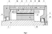
- Fig. 1 , Fig. 2 , and Fig.3 show an exemplary embodiment of the invention comprising a shaft 1 supported in front end bell 2 and rear end bell 3 by means of front bearing 4 and rear bearing 5.
- the front end bell 2 and the rear end bell 3 cover the stator 6.
- the stator 6 contains a housing 7 covering stationary stator pack 8 with inner diameter Da.
- On the inside surface of the stator pack 8 are formed a multitude of uniformly distributed slots 9. In each slot 9, an insulated hairpin-like winding of wires with a rectangular cross-section is laid.
- rotor 11 is movably covered.
- the rotor 11 contains a rotor pack 12 fixed immovably on shaft 1.
- 12 are formed poles, each of which contains a pair of mirror situated relative to the pole axial channels 13 located at an angle, open to the outer surface of the rotor 11.
- Each of the axial channels 13 is composed of two parts, each with two parallel walls - inner part 14 with rectangular cross-section and width b1 and height a1, and outer part 15 with width b2 and height a2.
- the inner parts 14 of the axial channels 13 are with a greater height a1 than the height a2 of the outer parts 15 located closer to the outer surface of the rotor 11.
- the height of the inserted permanent magnets 16 in the inner parts 14 of the axial channels 13 is greater than the height of the inserted permanent magnets 17 in the ones located closer to the surface of the rotor outer parts 15 of the axial channels 13. It is possible that the permanent magnets 16 inserted into the inner parts 14 of the axial channels 13 to be composed of two permanent magnets 17, whereby the number of types of permanent magnets is reduced to one. An inclined surface 18 is formed on both walls of each pole.
- the thickness d of the strips between the outer parts 15 of the axial channels 13 and the outer surface of the rotor 11 is limited to 0.0007 m.
- the outer walls 19, closing the empty spaces above the permanent magnets 17, and the walls to the adjacent poles of the outer parts 15 with widths b2 of the outer parts 15 of the axial channels 13 form an angle less than or equal to 180°.
- ducts 20 for coolant passage.
- sensor 21 To the back wall of the brushless electric motor with permanent magnet excitation is installed sensor 21 to control the commutation of the phases.
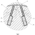
- Fig. 4 show a second exemplary embodiment of the brushless electric motor with permanent magnet excitation which differs from the above-described exemplary embodiment of the invention in that the air gap, formed between the inner surface of the stator pack 8 with diameter Da and the outer surface of the rotor 11 with a diameter Dr, is constant.
- the brushless electric motor with permanent magnet excitation is designed for driving vehicles, for driving main machine tools with CNC at two-zone rotation speed control.
- the rotation of the electric motor and the creation of torque take place when an electric current is applied to the stator winding 10 and its interaction with the magnetic field created by the permanent magnets 16 and 17.
- An additional reactionary torque is created at a displacement of the axes of the magnetic field created by the current flowing across the phases by phase shifting of the commutation of the current in the stator 6 relative to the axes of the magnetic field created by the permanent magnets 16 and 17 in the second zone of rotation speed control.
- the additional reactionary torque is increased due to the increase of the area between the permanent magnets 16, 17 of the adjacent poles, as well as the reduction of the air gap above this area.
- the relative increase in the reactionary torque is more significant at lower current loadings of the stator winding 10.
- the additional electrical losses in the stator winding 10 and in the iron by the third harmonic component in the magnetic field in the air gap are reduced, due: to the variable value of the air gap in the zone above the permanent magnets 17; to the reduced height of the end parts of the permanent magnets 17 located closer to the surface of the rotor 11; and to the reduced thickness of the strips between the channels in which the permanent magnets 17 are inserted and the rotor surface 11.
- the brushless electric motor according to the invention and at load conditions corresponding to S1 operation duty, consumes about 3000 W less compared to the known electric motor.
- the dimensions of the stator packs both of the known electric motor and the virtual specimen are the same.
- the quantity of the magnets on the virtual sample is with a 25% reduction.
- the duration of operation at peak load 192 kW at the known sample is 15 sec, and in the virtual sample, it is increased to 20 min.
- Losses of electric power at a load of about 110 kW at the virtual specimen are reduced by about 3 kW.
- the power corresponding to loading in continuous duty S1 in the virtual specimen is increased by about 40% compared to the known specimen.
- the efficiency at a load of 110 kW at the specimen according to the invention is increased by 2.8% compared to the known specimen.
Landscapes
- Engineering & Computer Science (AREA)
- Power Engineering (AREA)
- Permanent Magnet Type Synchronous Machine (AREA)
Applications Claiming Priority (1)
| Application Number | Priority Date | Filing Date | Title |
|---|---|---|---|
| BG113612A BG67728B1 (bg) | 2022-11-02 | 2022-11-02 | Безчетков електрически двигател с възбуждане от постоянни магнити |
Publications (1)
| Publication Number | Publication Date |
|---|---|
| EP4366137A1 true EP4366137A1 (de) | 2024-05-08 |
Family
ID=84887838
Family Applications (1)
| Application Number | Title | Priority Date | Filing Date |
|---|---|---|---|
| EP23150587.6A Pending EP4366137A1 (de) | 2022-11-02 | 2023-01-06 | Bustenlose electrishe machine mit permamentmagneterrenung |
Country Status (2)
| Country | Link |
|---|---|
| EP (1) | EP4366137A1 (de) |
| BG (1) | BG67728B1 (de) |
Citations (3)
| Publication number | Priority date | Publication date | Assignee | Title |
|---|---|---|---|---|
| DE10144585A1 (de) * | 2001-09-11 | 2003-04-30 | Vlado Ostovic | Kompositläufer für elektrische Maschinen |
| JP2014171372A (ja) * | 2013-03-05 | 2014-09-18 | Toyota Industries Corp | 回転電機の永久磁石埋設型回転子及び回転電機 |
| CN107394927A (zh) * | 2017-08-30 | 2017-11-24 | 广东威灵电机制造有限公司 | 转子铁芯和转子 |
-
2022
- 2022-11-02 BG BG113612A patent/BG67728B1/bg unknown
-
2023
- 2023-01-06 EP EP23150587.6A patent/EP4366137A1/de active Pending
Patent Citations (3)
| Publication number | Priority date | Publication date | Assignee | Title |
|---|---|---|---|---|
| DE10144585A1 (de) * | 2001-09-11 | 2003-04-30 | Vlado Ostovic | Kompositläufer für elektrische Maschinen |
| JP2014171372A (ja) * | 2013-03-05 | 2014-09-18 | Toyota Industries Corp | 回転電機の永久磁石埋設型回転子及び回転電機 |
| CN107394927A (zh) * | 2017-08-30 | 2017-11-24 | 广东威灵电机制造有限公司 | 转子铁芯和转子 |
Also Published As
| Publication number | Publication date |
|---|---|
| BG67728B1 (bg) | 2025-05-30 |
| BG113612A (bg) | 2024-05-15 |
Similar Documents
| Publication | Publication Date | Title |
|---|---|---|
| CN109510345B (zh) | 转子结构、异步起动同步磁阻电机及压缩机 | |
| EP0225132B1 (de) | Stator für eine elektrische Maschine | |
| CN107925289B (zh) | 定子线圈、配备定子线圈的定子、以及配备定子的旋转电机 | |
| US11799337B2 (en) | Rotating electric machine | |
| CN110771013B (zh) | 旋转电机的定子以及旋转电机 | |
| CN106165262A (zh) | 用于旋转电机的转子 | |
| EP3197019A1 (de) | Stator für elektrische drehmaschine und elektrische drehmaschine mit dem stator | |
| CN102326323A (zh) | 车辆用交流发电机 | |
| US4135107A (en) | Multi-phase alternating current machine with stepped stator | |
| US20180248453A1 (en) | Rotor, Rotating Electric Machine Including Said Rotor, and Method of Manufacturing Said Rotor | |
| CN105745818A (zh) | 电机以及用于制造电机的方法 | |
| GB2625418A (en) | Stator cooling | |
| EP4366137A1 (de) | Bustenlose electrishe machine mit permamentmagneterrenung | |
| US20220149677A1 (en) | Stator for a rotating electrical machine | |
| RU2538377C2 (ru) | Погружной линейный электродвигатель | |
| RU2246168C1 (ru) | Торцевая электрическая машина | |
| BG112334A (bg) | Електрическа машина с клюнообразни полюси | |
| JP2018148675A (ja) | 回転電機のステータ | |
| RU207794U1 (ru) | Синхронная электрическая машина торцевого типа | |
| CN113595350B (zh) | 一种自起动三相二级永磁同步电机 | |
| RU2286642C2 (ru) | Электрический двигатель постоянного тока индукторного типа | |
| CA3141849C (en) | Brushless electrical machine with permanent magnet excitation | |
| US12155283B2 (en) | Rotary electrical machine with an optimised configuration | |
| RU224471U1 (ru) | Синхронный бесколлекторный электродвигатель с независимым возбуждением | |
| BG4089U1 (bg) | Безчеткова електрическа машина с възбуждане от постоянни магнити |
Legal Events
| Date | Code | Title | Description |
|---|---|---|---|
| PUAI | Public reference made under article 153(3) epc to a published international application that has entered the european phase |
Free format text: ORIGINAL CODE: 0009012 |
|
| STAA | Information on the status of an ep patent application or granted ep patent |
Free format text: STATUS: REQUEST FOR EXAMINATION WAS MADE |
|
| 17P | Request for examination filed |
Effective date: 20230119 |
|
| AK | Designated contracting states |
Kind code of ref document: A1 Designated state(s): AL AT BE BG CH CY CZ DE DK EE ES FI FR GB GR HR HU IE IS IT LI LT LU LV MC ME MK MT NL NO PL PT RO RS SE SI SK SM TR |
|
| GRAP | Despatch of communication of intention to grant a patent |
Free format text: ORIGINAL CODE: EPIDOSNIGR1 |
|
| STAA | Information on the status of an ep patent application or granted ep patent |
Free format text: STATUS: GRANT OF PATENT IS INTENDED |
|
| RIC1 | Information provided on ipc code assigned before grant |
Ipc: H02K 1/276 20220101AFI20251129BHEP Ipc: H02K 29/06 20060101ALI20251129BHEP |
|
| INTG | Intention to grant announced |
Effective date: 20251218 |