EP4366136A1 - Rotor and motor - Google Patents
Rotor and motor Download PDFInfo
- Publication number
- EP4366136A1 EP4366136A1 EP22832547.8A EP22832547A EP4366136A1 EP 4366136 A1 EP4366136 A1 EP 4366136A1 EP 22832547 A EP22832547 A EP 22832547A EP 4366136 A1 EP4366136 A1 EP 4366136A1
- Authority
- EP
- European Patent Office
- Prior art keywords
- rotor core
- rotor
- cover
- plate
- magnetic pole
- Prior art date
- Legal status (The legal status is an assumption and is not a legal conclusion. Google has not performed a legal analysis and makes no representation as to the accuracy of the status listed.)
- Pending
Links
Images









Classifications
-
- H—ELECTRICITY
- H02—GENERATION; CONVERSION OR DISTRIBUTION OF ELECTRIC POWER
- H02K—DYNAMO-ELECTRIC MACHINES
- H02K1/00—Details of the magnetic circuit
- H02K1/06—Details of the magnetic circuit characterised by the shape, form or construction
- H02K1/22—Rotating parts of the magnetic circuit
- H02K1/27—Rotor cores with permanent magnets
- H02K1/2706—Inner rotors
- H02K1/272—Inner rotors the magnetisation axis of the magnets being perpendicular to the rotor axis
- H02K1/274—Inner rotors the magnetisation axis of the magnets being perpendicular to the rotor axis the rotor consisting of two or more circumferentially positioned magnets
- H02K1/2753—Inner rotors the magnetisation axis of the magnets being perpendicular to the rotor axis the rotor consisting of two or more circumferentially positioned magnets the rotor consisting of magnets or groups of magnets arranged with alternating polarity
- H02K1/276—Magnets embedded in the magnetic core, e.g. interior permanent magnets [IPM]
- H02K1/2766—Magnets embedded in the magnetic core, e.g. interior permanent magnets [IPM] having a flux concentration effect
- H02K1/2773—Magnets embedded in the magnetic core, e.g. interior permanent magnets [IPM] having a flux concentration effect consisting of tangentially magnetized radial magnets
-
- H—ELECTRICITY
- H02—GENERATION; CONVERSION OR DISTRIBUTION OF ELECTRIC POWER
- H02K—DYNAMO-ELECTRIC MACHINES
- H02K1/00—Details of the magnetic circuit
- H02K1/06—Details of the magnetic circuit characterised by the shape, form or construction
- H02K1/22—Rotating parts of the magnetic circuit
- H02K1/27—Rotor cores with permanent magnets
- H02K1/2706—Inner rotors
- H02K1/272—Inner rotors the magnetisation axis of the magnets being perpendicular to the rotor axis
- H02K1/274—Inner rotors the magnetisation axis of the magnets being perpendicular to the rotor axis the rotor consisting of two or more circumferentially positioned magnets
Definitions
- the present invention relates to a rotor and a motor.
- IPM rotors In inner rotor type motors, so-called IPM rotors are known.
- IPM rotors plate-shaped magnets magnetized in front and back directions are disposed in a spoke-like shape in a radial direction so that two adjacent plate-shaped magnets repel each other.
- a locking structure is sometimes used for preventing the plate-shaped magnet from jumping outward in the radial direction due to a repulsive force with an adjacent plate-shaped magnet or a centrifugal force when the rotor rotates.
- an object is to provide a rotor and a motor capable of improving motor characteristics.
- a rotor in one aspect, includes a rotor core, a magnet, and a cover.
- the rotor core includes an annular portion and a plurality of magnetic pole pieces.
- the magnet is disposed between two magnetic pole pieces adjacent to each other in a circumferential direction of the plurality of magnetic pole pieces.
- the cover covers an outer peripheral portion of the magnet, and is formed of a non-magnetic material or a member having magnetism lower than magnetism of the rotor core.
- the motor characteristics can be improved.
- FIG. 1 An embodiment of a rotor disclosed in the present application will be elaborated below with reference to the drawings. Note that the dimensional relationships between elements and the ratios of the elements in the drawings may differ from an actual configuration.
- the drawings may include parts having mutually different dimensional relationships and proportions.
- a coordinate system including at least any one of an axial direction (rotation axis direction of a motor 1), a radial direction, or a circumferential direction of the motor 1 may be illustrated for the purpose of facilitating explanation.
- the motor 1 will be described later.
- the rotation axis direction of the motor 1 may be simply referred to as an "axial direction" below.
- FIG. 1 is a perspective view illustrating one example of a motor according to a first embodiment. However, a stator is omitted in FIG. 1 .
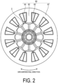
- FIG. 2 is a cross-sectional view illustrating one example of the motor according to the first embodiment. FIG. 2 illustrates a cross section taken along the line A-A in FIG. 1 .
- the motor 1 according to the present embodiment includes a rotor 2 and a stator 80. Note that the motor 1 described in each embodiment is an inner rotor type brushless motor. Further, the motor 1 in each embodiment is housed in, for example, a frame (not illustrated).
- the stator 80 includes a yoke 81, teeth 82, coils 83, and insulators 84.
- the yoke 81 is an annular member formed at the outer peripheral side of the stator 80.
- the teeth 82 protrude inward in the radial direction from the yoke 81.
- the yoke 81 and the teeth 82 are formed by, for example, punching a flat plate-shaped member formed of a magnetic material such as a magnetic steel plate into a shape illustrated in FIG. 2 and stacking a plurality of the punched members in the axial direction.
- the coils 83 are wound around the teeth 82 via the insulators 84, for example.
- the rotor 2 is rotatably inserted into the stator 80 in the radial direction.
- the rotor 2 includes a rotor core 10, covers 20 and 30, a plurality of plate-shaped magnets 40, and a shaft 90.
- the shaft 90 is inserted into the rotor 2 in the radial direction.
- the rotor core 10 has a stacked structure obtained by stacking a plurality of steel plate cores formed of a soft magnetic material such as a silicon steel plate.
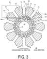
- FIG. 3 is a cross-sectional view illustrating an example of a rotor core according to the first embodiment.
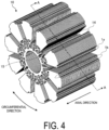
- FIG. 4 is a perspective view illustrating an example of the rotor core according to the first embodiment.
- FIG. 3 illustrates a cross section taken along the line A-A in FIG. 4 .
- the rotor core 10 includes a plurality of magnetic pole pieces 11, coupling portions 12, support portions 15, and an annular portion 19.
- the rotor core 10 may further include lightening portions 16, 17, and 18 in order to reduce leakage magnetic flux.
- the magnetic pole pieces 11 when the magnetic pole pieces 11 are distinguished from each other, they may be referred to as magnetic pole pieces 11A to 11J below.
- the plurality of magnetic pole pieces 11 extend outward in the radial direction from the annular portion 19.
- the plurality of magnetic pole pieces 11 are arranged side by side in the circumferential direction.
- Each of the magnetic pole pieces 11 includes end portions 11p and 11q extending substantially in the radial direction and an outer peripheral portion 11r extending in the circumferential direction.
- the end portion 11p opposes, across a gap 14 in the circumferential direction, the end portion 11q of the circumferentially adjacent magnetic pole piece 11.
- the outer peripheral portion 11r constitutes the outer periphery of the rotor 2.
- FIG. 5 is an enlarged cross-sectional view illustrating an example of a recessed portion of the rotor core according to the first embodiment.
- FIG. 5 is an enlarged view of a portion illustrated in a frame F1 in FIG. 3 . As illustrated in FIG.
- the recessed portion 1a includes a first portion 1c connected to the outer peripheral portion 11r, and a second portion 1e constituting an inner diameter-side end portion of the recessed portion 1a and connected to the end portion 11p.
- the recessed portion 1b includes a first portion 1d connected to the outer peripheral portion 11r, and a second portion 1f constituting an inner diameter-side end portion of the recessed portion 1b and connected to the end portion 11q. Note that the outer peripheral portion 11r, the first portion 1c of the recessed portion 1a, and the second portion 1e of the recessed portion 1a are continuously formed.
- the outer peripheral portion 11r, the first portion 1d of the recessed portion 1b, and the second portion 1f of the recessed portion 1b are continuously formed.
- the outer peripheral portion 11r, the second portion 1e of the recessed portion 1a, and the second portion 1f of the recessed portion 1b constitute an outer peripheral end portion of the rotor core 10.
- the recessed portion 1b formed at the magnetic pole piece 11A opposes, in the circumferential direction, the recessed portion 1a formed at the magnetic pole piece 11J circumferentially adjacent to the magnetic pole piece 11A. More specifically, the first portion 1d of the recessed portion 1b of the magnetic pole piece 11A and the first portion 1c of the recessed portion 1a of the magnetic pole piece 11J oppose each other in the circumferential direction. Further, as illustrated in FIG. 5 , the recessed portion 1b is formed such that an angle R formed by the second portion 1f and the end portion 11q is an acute angle. The same applies to the recessed portion 1a.
- the shaft 90 is inserted into the annular portion 19 in the radial direction via the inner peripheral portions 29 and 39 of the covers 20 and 30.
- the plurality of magnetic pole pieces 11 and the annular portion 19 are coupled to each other in the radial direction by the coupling portions 12.
- the inner diameter of the annular portion 19 is formed to be larger than the outer diameters of the inner peripheral portions 29 and 39 of the covers 20 and 30.
- the support portion 15 extends outward in the radial direction from the annular portion 19. In other words, the support portion 15 protrudes outward in the radial direction from the annular portion 19. As illustrated in FIG. 3 , the support portion 15 opposes the gap 14 in the radial direction.
- the width of the gap 14 is formed to be substantially the same as or slightly larger than the width (the length in the circumferential direction) of the plate-shaped magnet 40.
- air layers 14a and 14b are formed at both sides in the circumferential direction at the inner side in the radial direction of the gap 14, respectively. Note that at this time, the air layer 14a and the air layer 14b are disposed adjacent to each other in the circumferential direction of the support portion 15.
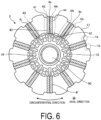
- FIG. 6 is a cross-sectional view illustrating an example of the rotor according to the first embodiment.
- FIG. 6 illustrates a cross section of the rotor 2 taken along the line A-A in FIG. 4 .
- the rotor 2 in the present embodiment includes ten plate-shaped magnets 40. Note that when the plate-shaped magnets 40 are distinguished from each other, they may be referred to as plate-shaped magnets 4a to 4j below.
- the plate-shaped magnet 40 includes a radially outer end surface 41, a radially inner end surface 42, a circumferentially counterclockwise-side end surface 43, and a circumferentially clockwise-side end surface 44.
- the plate-shaped magnet 40 includes an N-pole 4N and an S-pole 4S.
- two plate-shaped magnets 40 adjacent to each other in the circumferential direction are disposed such that the same poles oppose each other.
- two plate-shaped magnets 4a and 4b adjacent to each other in the circumferential direction are disposed such that the N-poles 4N oppose each other.
- the two plate-shaped magnets 4j and 4a adjacent to each other in the circumferential direction are disposed such that the S-poles 4S oppose each other.
- the radially inner end surface 42 of the plate-shaped magnet 40 is supported in the radial direction by the support portion 15 of the rotor core 10. Specifically, the end surface 42 is supported by the support portion 15 in the vicinity of the center of the plate-shaped magnet 40 in the circumferential direction.
- the support portion 15 supports a switching point, and the N-pole 4N and the S-pole 4S of the plate-shaped magnets 40 are switched at the switching point.
- the air layer 14a and 14b are provided at both end portions of the end surface 42 in the circumferential direction without a conventional locking structure, the magnetic flux generated from both end portions of the end surface 42 in the circumferential direction are guided to the rotor core 10.
- the magnetic flux not interlinking with the stator winding and directly flowing into the opposite magnetic pole at the other surface of the plate-shaped magnet decreases. According to such a configuration, it is possible to suppress leakage of the magnetic flux from both end portions in the circumferential direction at the radially inner side of the plate-shaped magnet 40.
- FIG. 7 is a perspective view illustrating an example of a cover according to the first embodiment.
- FIG. 7 is a perspective view illustrating an example of a cover according to the first embodiment.
- FIG. 8 is a cross-sectional perspective view illustrating an example of the cover according to the first embodiment.
- FIG. 8 illustrates a cross section taken along the line C-C in FIG. 7 .
- the cover 20 is attached to the rotor core 10 from the positive direction side in the axial direction
- the cover 30 is attached to the rotor core 10 from the negative direction side in the axial direction.
- the cover 20 includes a plurality of protruding portions 21, a planar portion 25, and an inner peripheral portion 29. Further, the cover 20 may further include a plurality of opening portions 22. Note that although the cover 20 is illustrated in FIG. 7 and the cover 30 is illustrated in FIG. 8 , the covers 20 and 30 in the present embodiment have the same shape, and matters described below with respect to the cover 20 also apply to the cover 30 unless otherwise specified.
- the cover 30 also includes a plurality of protruding portions 31, a planar portion 35, an inner peripheral portion 39, and a plurality of opening portions 32. Similarly, matters described with respect to the cover 30 also apply to the cover 20 unless otherwise specified.
- the cover 20 is formed of a non-magnetic material such as brass. Further, the cover 20 may be formed by bending a material having magnetism lower than magnetism of the magnetic steel plate constituting the rotor core 10, such as austenitic stainless steel.
- each of the protruding portions 21 protrudes from the planar portion 25 in the axial direction.
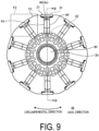
- the plurality of protruding portions 21 are arranged at equal intervals in the circumferential direction. More specifically, as illustrated in FIGS. 9 and 10 , the same number of protruding portions 21 as the number of plate-shaped magnets 40 are formed at positions in contact with parts of the plate-shaped magnets 40, for example, parts of the end surfaces 41 at the axially positive direction side.
- FIG. 9 is a cross-sectional view illustrating an example of the rotor core according to the first embodiment. In FIG. 9 , the plate-shaped magnets are omitted. FIG.
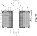
- FIG. 10 is a side cross-sectional view illustrating an example of the rotor core according to the first embodiment.
- FIG. 10 illustrates a cross section taken along the line B-B in FIGS. 1 and 9.
- FIG. 9 illustrates a cross section taken along the line D-D in FIG. 1 or FIG. 10 .
- the plate-shaped magnet 40 in addition to the end surfaces 41 to 44 illustrated in FIGS. 6 and 9 , the plate-shaped magnet 40 further includes an end surface 45 at the axially positive direction side and an end surface 46 at the axially negative direction side.
- each protruding portion 21 of the cover 20 protrudes toward the axially negative direction side
- each protruding portion 31 of the cover 30 protrudes toward the axially positive direction side.
- a part at the axially positive direction side is in contact with the protruding portion 21 of the cover 20
- a part at the axially negative direction side is in contact with the protruding portion 31 of the cover 30.
- the opening portions 22 are formed extending through the planar portion 25 in the axial direction. As illustrated in FIG. 10 , the opening portions 22 oppose the end surfaces 45 of the plate-shaped magnets 40 at the axially positive direction side. In this case, as illustrated in FIG. 1 , the plate-shaped magnets 40 are visually recognized from the axially positive direction side through the opening portions 22.
- the inner peripheral portion 29 protrudes from the planar portion 25 in the axial direction similarly to the protruding portion 21.
- the outer diameter of the inner peripheral portion 29 is, for example, substantially the same as or slightly larger than the inner diameter of the annular portion 19 of the rotor core 10.
- the inner diameter of the inner peripheral portion 29 is, for example, substantially the same as or slightly smaller than the outer diameter of the shaft 90.
- the covers 20 and 30 are inserted by being press-fitted between the annular portion 19 of the rotor core 10 and the shaft 90 in the radial direction.
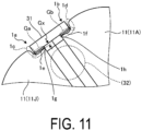
- FIG. 11 is an enlarged cross-sectional view illustrating an example of the rotor according to the first embodiment.
- FIG. 11 is an enlarged view of a portion indicated by a frame F2 in FIG. 9 .
- the radially outer end surface 41 of the plate-shaped magnet 40 is in contact with the protruding portion 31 of the cover 30, and protrudes outward in the radial direction beyond the recessed portions 1a and 1b, more specifically, beyond the second portion 1e of the recessed portion 1a and the second portion 1f of the recessed portion 1b.
- a gap Ga in the radial direction is formed between the protruding portion 31 and the second portion 1e of the recessed portion 1a of the rotor core 10.
- a gap Gb in the radial direction is formed between the protruding portion 31 and the second portion 1f of the recessed portion 1b. Further, a gap Gx in the radial direction is formed between corner portions 1g and 1h and the cover 20. In the present embodiment, the corner portions 1g and 1h have an acute angle (angle R illustrated in FIG. 5 ).
- the covers 20, 30 can be easily disposed, and the length of the magnetic path of the leakage magnetic flux is increased and the magnetic resistance is increased, so that the leakage magnetic flux can be suppressed.
- the corner portions 1g and 1h to have an acute angle, the magnetic path of the leakage magnetic flux connected from the recessed portions 1a and 1b to the other recessed portion also goes out to the air layer substantially perpendicularly from the recessed portions 1a and 1b.
- the distance to the other recessed portion can be further increased, and the magnetic resistance is increased, so that the leakage of the magnetic flux is further suppressed.
- each of the magnetic pole pieces 11 it is not necessary to install a locking structure by the rotor core, and the plate-shaped magnet 40 protrudes outward in the radial direction from the recessed portions 1a and 1b of the rotor core 10 but is positioned inward in the radial direction of the outer peripheral portion 11r. According to such a configuration, cogging and torque ripple can be easily adjusted by changing the width or curvature of the outer peripheral portion 11r.
- the rotor 2 in the present embodiment includes the rotor core 10, the magnets 40, and the covers 20, 30.
- the rotor core 10 includes the annular portion 19 and the plurality of magnetic pole pieces 11.
- the magnet 40 is disposed between two magnetic pole pieces adjacent to each other in a circumferential direction of the plurality of magnetic pole pieces 11.
- the cover 20, 30 covers the outer peripheral portion of the magnets 40, and is formed of a non-magnetic member or a member having magnetism lower than magnetism of the rotor core 10. According to such a configuration, the leakage of the magnetic flux via the rotor core 10 can be suppressed, so that the motor characteristics can be improved.
- the two adjacent magnetic pole pieces 11 include the recessed portions 1a and 1b recessed in the radial direction, and the recessed portions 1a and 1b included in the two adjacent magnetic pole pieces 11 are each disposed opposing the magnet 40 in the circumferential direction. Further, in the radial direction, the gaps Ga and Gb are formed between inner diameter-side end portions 1e and 1f of the recessed portions 1a and 1b and the covers 20 and 30. According to such a configuration, it is possible to suppress the magnetic flux leaking outward in the radial direction.
- the covers 20 and 30 are formed of a non-magnetic member or a member having magnetism lower than magnetism of a member forming the magnetic pole piece 11 of the rotor core 10.
- the plate-shaped magnet 40 of the present embodiment at least parts of the radially outer end surface 41 are in contact with the non-magnetic or low-magnetic covers 20 and 30. Since a locking structure by the rotor core 10 is not disposed in the radial direction at the radially outer end surface 41 of the plate-shaped magnet 40, the magnetic flux not interlinking with the stator winding and directly flowing into the opposite magnetic pole at the other surface of the plate-shaped magnet is suppressed. According to such a configuration, the leakage magnetic flux is reduced.
- the cover 20 in the present embodiment may include the opening portions 22 opening in the axial direction.
- the opening portions 22 oppose the magnets 40 in the axial direction.
- the plate-shaped magnets 40 and the rotor core 10 can be easily fixed to each other by injecting an adhesive or the like from the opening portions 22.
- FIG. 12 is a perspective view illustrating an example of a rotor according to a second embodiment.
- a motor A1 according to the second embodiment includes a rotor A2 and a stator 80.
- the stator is omitted in FIG. 12 . Note that in the following embodiment and modifications, the same portions as those illustrated in the drawings described above are denoted by the same reference signs, and the redundant description will be omitted.
- the rotor A2 illustrated in FIG. 12 includes a rotor core 50, covers 60 and 70, plate-shaped magnets 40, and a shaft 90.
- the rotor core 50 includes a plurality of magnetic pole pieces 51, coupling portions 52, and an annular portion 59.
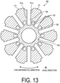
- FIG. 13 is a cross-sectional view illustrating an example of a rotor core according to the second embodiment.
- the magnetic pole piece 51 in the second embodiment includes the outer peripheral portion 11r extending in the circumferential direction, and end portions 51p and 51q extending in the radial direction.
- the plurality of magnetic pole pieces 51 and the annular portion 59 are coupled to each other in the radial direction by the coupling portions 52.
- the magnetic pole piece 51 may further include a lightening portion 58.
- FIG. 14 is a cross-sectional view illustrating an example of the rotor according to the second embodiment.
- the end portions 51p and 51q in the second embodiment extend inward in the radial direction beyond the radially inner end surface 42 of the plate-shaped magnet 40.
- the radially inner end surface 42 of the plate-shaped magnet 40 in the second embodiment is supported not by the support portion 15 but by the cover 70.
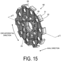
- FIG. 15 is a perspective view illustrating one example of a cover according to the second embodiment.
- FIG. 16 is a cross-sectional perspective view illustrating an example of the cover according to the second embodiment.
- FIG. 16 illustrates a cross section taken along the line C-C in FIG. 15 .
- the covers 60 and 70 have the same shape, and matters described below with respect to the cover 60 also apply to the cover 70 unless otherwise specified. Similarly, matters described with respect to the cover 70 also apply to the cover 60 unless otherwise specified.
- the cover 60 is formed of a non-magnetic material such as brass or a material having magnetism lower than magnetism of the magnetic steel plate constituting the rotor core 50. As illustrated in FIG. 15 , the cover 60 further includes contact portions 66 in addition to the protruding portions 21, the opening portions 22, the planar portion 25, and the inner peripheral portion 29.
- the contact portions 66 of the cover 60 protrude from the planar portion 25 in the axial direction, similarly to the protruding portions 21 and the inner peripheral portion 29.
- the contact portions 66 are arranged at equal intervals in the circumferential direction to oppose the plate-shaped magnets 40 in the radial direction, and the number of the contact portions 66 is the same as the number of the plate-shaped magnets 40.
- portions extending through the planar portion 25 in the axial direction are formed around the contact portions 66.
- the contact portions 66 of the cover 60 protrude toward the axially negative direction side
- the contact portions 76 of the cover 70 protrude toward the axially positive direction side.
- FIG. 17 is a side cross-sectional view illustrating an example of the rotor according to the second embodiment.
- the contact portion 66 is inserted into the gap 54 of the rotor core 50 from the axially positive direction side.
- the contact portion 66 supports the radially inner end surface 42 of the plate-shaped magnet 40 from the radially inner side.
- the plate-shaped magnet 40 is supported in the radial direction by the protruding portion 21 and the contact portion 66 of the cover 60, and by the protruding portion 31 and the contact portion 76 of the cover 70.
- the cover 60 includes the contact portions 66, and the contact portions 66 are in contact with the magnets 40 at the radially inner end surfaces 42 of the magnets 40. According to such a configuration, leakage of the magnetic flux not interlinking with the stator winding and directly flowing into the opposite magnetic pole at the other surface of the plate-shaped magnet from one of the radially inner end surfaces of the plate-shaped magnet 40 is suppressed.
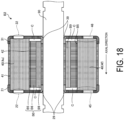
- FIG. 18 is a side cross-sectional view illustrating an example of a rotor according to a first modification.
- the axial length of the rotor core B0 is smaller than the length of the plate-shaped magnet 40.
- a space C is formed between the rotor core B0 and the covers 20 and 30 in the axial direction.
- the end surfaces 45 and 46 of the plate-shaped magnet 40 in the axial direction do not oppose a support portion B5 of the rotor core B0 in the radial direction.
- the inner peripheral portion 29 of the cover 20 and the inner peripheral portion 39 of the cover 30 are disposed between the end surfaces 45 and 46, and the shaft 90 opposing the plate-shaped magnets 40 in the radial direction.
- the magnetic flux of the plate-shaped magnet 40 can be converged into a range opposing the stator, and the magnetic flux interlinking with the stator winding can be increased, whereby the characteristics of the motor can be improved.
- the end portion in the axial direction of the radially outer end surface 41 of the plate-shaped magnet 40 is, in the entire circumferential direction, in contact with the protruding portion 21, and the recessed portions 1a and 1b are in contact with the vertex of the protruding portion 21.
- the embodiment is not limited to this.
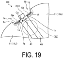
- a rotor core C0 may be configured such that only a part of the plate-shaped magnet 40 in the circumferential direction, more specifically, only the vicinity of the central portion in the circumferential direction is in contact with a protruding portion C31.
- FIG. 19 is an enlarged cross-sectional view illustrating an example of a rotor according to a second modification.
- the protruding portion C31 of a cover C30 is in contact with neither of the recessed portions 1a and 1b.
- the protruding portion C31 may cover only the central portion of the plate-shaped magnet 40 as illustrated in FIG. 19 .
- the outer peripheral portion 11r, the first portion 1c, the second portion 1e, and the end portion 11p illustrated in FIG. 5 are continuously connected by, for example, a curved line but, as this is not a limitation, may be discontinuously formed in straight lines.
- the outer peripheral portion 11r, the first portion 1d, the second portion 1f, and the end portion 11q may be formed in a curved shape.
- the first portions 1c and 1d may be in contact with the entire end surfaces of the protruding portion 21 of the cover 20 in the circumferential direction.
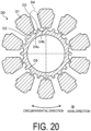
- air layers extending in the circumferential direction and corresponding to the reference signs 14a and 14b of FIG. 3 are not formed at the radially inner side of the gap 54, but this is not a limitation, and as illustrated in FIG. 20 , an annular portion D9 and support portions D5 protruding outward in the radial direction from the annular portion D9 may be provided, and air layers D4a and D4b extending in the circumferential direction of a gap D4 may be provided. In other words, the support portion D5 and the air layers D4a and D4b are disposed adjacent to each other in the circumferential direction.
- FIG. 20 is a cross-sectional view illustrating an example of a rotor core according to a third modification.
- a rotor core D0 of the third modification as well, a plurality of magnetic pole pieces D1 and an annular portion D9 are coupled in the radial direction by coupling portions D2. According to such a configuration, it is possible to suppress leakage of the magnetic flux from both end portions in the circumferential direction at the radially inner side of the plate-shaped magnet 40.
- FIG. 21 is a cross-sectional view illustrating an example of a rotor according to a fourth modification.
- the outer peripheral portion E1r and the end portions E1p and E1q are continuously disposed. According to such a configuration, even a multi-pole or small-diameter rotor core E0 can be easily manufactured.
- the protruding portion C31 of the cover C30 in the fourth modification is in contact with only the vicinity of the central portion of the plate-shaped magnet 40 in the circumferential direction as in the second modification.
- the radially inner end surface 42 of the plate-shaped magnet 40 is supported by a contact portion C36 of the cover C30 but, as this is not a limitation, may be supported by the support portion D5 of the rotor core D0 as illustrated in FIG. 20 .
- a configuration corresponding to the coupling portions 52 in FIG. 13 is not provided, but the lightening portions 58 and the coupling portions 52 may be provided similarly to FIG. 13 .
Landscapes
- Engineering & Computer Science (AREA)
- Power Engineering (AREA)
- Permanent Field Magnets Of Synchronous Machinery (AREA)
- Iron Core Of Rotating Electric Machines (AREA)
Abstract
Description
- The present invention relates to a rotor and a motor.
- In inner rotor type motors, so-called IPM rotors are known. In IPM rotors, plate-shaped magnets magnetized in front and back directions are disposed in a spoke-like shape in a radial direction so that two adjacent plate-shaped magnets repel each other. In IPM rotors, a locking structure is sometimes used for preventing the plate-shaped magnet from jumping outward in the radial direction due to a repulsive force with an adjacent plate-shaped magnet or a centrifugal force when the rotor rotates.
-
- Patent Document 1:
WO 2018/043288 - Patent Document 2:
JP 2012-200053 A - However, when leakage magnetic flux from the plate-shaped magnet is generated via the locking structure, the magnetic flux interlinking from the plate-shaped magnet to a coil of a stator is reduced, and thus the motor characteristics may be degraded.
- In one aspect, an object is to provide a rotor and a motor capable of improving motor characteristics.
- In one aspect, a rotor includes a rotor core, a magnet, and a cover. The rotor core includes an annular portion and a plurality of magnetic pole pieces. The magnet is disposed between two magnetic pole pieces adjacent to each other in a circumferential direction of the plurality of magnetic pole pieces. The cover covers an outer peripheral portion of the magnet, and is formed of a non-magnetic material or a member having magnetism lower than magnetism of the rotor core.
- According to one aspect, the motor characteristics can be improved.
-
-
FIG. 1 is a perspective view illustrating an example of a motor according to a first embodiment. -
FIG. 2 is a cross-sectional view illustrating an example of the motor according to the first embodiment. -
FIG. 3 is a cross-sectional view illustrating an example of a rotor core according to the first embodiment. -
FIG. 4 is a perspective view illustrating an example of the rotor core according to the first embodiment. -
FIG. 5 is an enlarged cross-sectional view illustrating an example of a recessed portion of the rotor core according to the first embodiment. -
FIG. 6 is a cross-sectional view illustrating an example of the rotor according to the first embodiment. -
FIG. 7 is a perspective view illustrating an example of a cover according to the first embodiment. -
FIG. 8 is a cross-sectional perspective view illustrating an example of the cover according to the first embodiment. -
FIG. 9 is a cross-sectional view illustrating an example of the rotor core according to the first embodiment. -
FIG. 10 is a side cross-sectional view illustrating an example of the rotor core according to the first embodiment. -
FIG. 11 is an enlarged cross-sectional view illustrating an example of the rotor according to the first embodiment. -
FIG. 12 is a perspective view illustrating an example of a rotor according to a second embodiment. -
FIG. 13 is a cross-sectional view illustrating an example of a rotor core according to the second embodiment. -
FIG. 14 is a cross-sectional view illustrating an example of the rotor according to the second embodiment. -
FIG. 15 is a perspective view illustrating an example of a cover according to the second embodiment. -
FIG. 16 is a cross-sectional perspective view illustrating an example of the cover according to the second embodiment. -
FIG. 17 is a side cross-sectional view illustrating an example of the rotor according to the second embodiment. -
FIG. 18 is a side cross-sectional view illustrating an example of a rotor according to a first modification. -
FIG. 19 is an enlarged cross-sectional view illustrating an example of a rotor according to a second modification. -
FIG. 20 is a cross-sectional view illustrating an example of a rotor core according to a third modification. -
FIG. 21 is a cross-sectional view illustrating an example of a rotor according to a fourth modification. - An embodiment of a rotor disclosed in the present application will be elaborated below with reference to the drawings. Note that the dimensional relationships between elements and the ratios of the elements in the drawings may differ from an actual configuration. The drawings may include parts having mutually different dimensional relationships and proportions. In each of the drawings, a coordinate system including at least any one of an axial direction (rotation axis direction of a motor 1), a radial direction, or a circumferential direction of the
motor 1 may be illustrated for the purpose of facilitating explanation. Themotor 1 will be described later. In addition, the rotation axis direction of themotor 1 may be simply referred to as an "axial direction" below. - First, a
motor 1 of the present embodiment will be described with reference toFIG. 1 andFIG. 2 .FIG. 1 is a perspective view illustrating one example of a motor according to a first embodiment. However, a stator is omitted inFIG. 1 .FIG. 2 is a cross-sectional view illustrating one example of the motor according to the first embodiment.FIG. 2 illustrates a cross section taken along the line A-A inFIG. 1 . As illustrated inFIG. 1 , themotor 1 according to the present embodiment includes arotor 2 and astator 80. Note that themotor 1 described in each embodiment is an inner rotor type brushless motor. Further, themotor 1 in each embodiment is housed in, for example, a frame (not illustrated). - As illustrated in
FIG. 2 , thestator 80 includes ayoke 81,teeth 82,coils 83, andinsulators 84. Theyoke 81 is an annular member formed at the outer peripheral side of thestator 80. Theteeth 82 protrude inward in the radial direction from theyoke 81. Theyoke 81 and theteeth 82 are formed by, for example, punching a flat plate-shaped member formed of a magnetic material such as a magnetic steel plate into a shape illustrated inFIG. 2 and stacking a plurality of the punched members in the axial direction. Thecoils 83 are wound around theteeth 82 via theinsulators 84, for example. - As illustrated in
FIGS. 1 and2 , therotor 2 is rotatably inserted into thestator 80 in the radial direction. Therotor 2 includes arotor core 10, covers 20 and 30, a plurality of plate-shaped magnets 40, and ashaft 90. For example, theshaft 90 is inserted into therotor 2 in the radial direction. - The
rotor core 10 has a stacked structure obtained by stacking a plurality of steel plate cores formed of a soft magnetic material such as a silicon steel plate.FIG. 3 is a cross-sectional view illustrating an example of a rotor core according to the first embodiment.FIG. 4 is a perspective view illustrating an example of the rotor core according to the first embodiment.FIG. 3 illustrates a cross section taken along the line A-A inFIG. 4 . As illustrated inFIGS. 3 and4 , therotor core 10 includes a plurality ofmagnetic pole pieces 11,coupling portions 12,support portions 15, and anannular portion 19. Note that therotor core 10 may further include lighteningportions magnetic pole pieces 11 are distinguished from each other, they may be referred to asmagnetic pole pieces 11A to 11J below. - The plurality of
magnetic pole pieces 11 extend outward in the radial direction from theannular portion 19. The plurality ofmagnetic pole pieces 11 are arranged side by side in the circumferential direction. Each of themagnetic pole pieces 11 includesend portions peripheral portion 11r extending in the circumferential direction. Theend portion 11p opposes, across agap 14 in the circumferential direction, theend portion 11q of the circumferentially adjacentmagnetic pole piece 11. The outerperipheral portion 11r constitutes the outer periphery of therotor 2. - As illustrated in
FIGS. 3 and5 , a recessedportion 1a cut out in the circumferential direction and the radial direction is formed at one side in the circumferential direction of each outerperipheral portion 11r. Further, a recessedportion 1b cut out in the circumferential direction and the radial direction is formed at the other side in the circumferential direction of each outerperipheral portion 11r.FIG. 5 is an enlarged cross-sectional view illustrating an example of a recessed portion of the rotor core according to the first embodiment.FIG. 5 is an enlarged view of a portion illustrated in a frame F1 inFIG. 3 . As illustrated inFIG. 5 , the recessedportion 1a includes afirst portion 1c connected to the outerperipheral portion 11r, and asecond portion 1e constituting an inner diameter-side end portion of the recessedportion 1a and connected to theend portion 11p. Similarly, the recessedportion 1b includes afirst portion 1d connected to the outerperipheral portion 11r, and asecond portion 1f constituting an inner diameter-side end portion of the recessedportion 1b and connected to theend portion 11q. Note that the outerperipheral portion 11r, thefirst portion 1c of the recessedportion 1a, and thesecond portion 1e of the recessedportion 1a are continuously formed. Similarly, the outerperipheral portion 11r, thefirst portion 1d of the recessedportion 1b, and thesecond portion 1f of the recessedportion 1b are continuously formed. In other words, the outerperipheral portion 11r, thesecond portion 1e of the recessedportion 1a, and thesecond portion 1f of the recessedportion 1b constitute an outer peripheral end portion of therotor core 10. - As illustrated in
FIG. 5 , the recessedportion 1b formed at themagnetic pole piece 11A opposes, in the circumferential direction, the recessedportion 1a formed at themagnetic pole piece 11J circumferentially adjacent to themagnetic pole piece 11A. More specifically, thefirst portion 1d of the recessedportion 1b of themagnetic pole piece 11A and thefirst portion 1c of the recessedportion 1a of themagnetic pole piece 11J oppose each other in the circumferential direction. Further, as illustrated inFIG. 5 , the recessedportion 1b is formed such that an angle R formed by thesecond portion 1f and theend portion 11q is an acute angle. The same applies to the recessedportion 1a. - The
shaft 90 is inserted into theannular portion 19 in the radial direction via the innerperipheral portions covers magnetic pole pieces 11 and theannular portion 19 are coupled to each other in the radial direction by thecoupling portions 12. In the present embodiment, the inner diameter of theannular portion 19 is formed to be larger than the outer diameters of the innerperipheral portions covers - The
support portion 15 extends outward in the radial direction from theannular portion 19. In other words, thesupport portion 15 protrudes outward in the radial direction from theannular portion 19. As illustrated inFIG. 3 , thesupport portion 15 opposes thegap 14 in the radial direction. In the present embodiment, for example, the width of thegap 14 is formed to be substantially the same as or slightly larger than the width (the length in the circumferential direction) of the plate-shapedmagnet 40. Further, air layers 14a and 14b are formed at both sides in the circumferential direction at the inner side in the radial direction of thegap 14, respectively. Note that at this time, theair layer 14a and theair layer 14b are disposed adjacent to each other in the circumferential direction of thesupport portion 15. - As illustrated in
FIG. 6 , the plate-shapedmagnet 40 is inserted into thegap 14 of therotor core 10.FIG. 6 is a cross-sectional view illustrating an example of the rotor according to the first embodiment.FIG. 6 illustrates a cross section of therotor 2 taken along the line A-A inFIG. 4 . Therotor 2 in the present embodiment includes ten plate-shapedmagnets 40. Note that when the plate-shapedmagnets 40 are distinguished from each other, they may be referred to as plate-shapedmagnets 4a to 4j below. - As illustrated in
FIG. 6 , the plate-shapedmagnet 40 includes a radiallyouter end surface 41, a radiallyinner end surface 42, a circumferentially counterclockwise-side end surface 43, and a circumferentially clockwise-side end surface 44. As illustrated inFIG. 6 , the plate-shapedmagnet 40 includes an N-pole 4N and an S-pole 4S. In the present embodiment, two plate-shapedmagnets 40 adjacent to each other in the circumferential direction are disposed such that the same poles oppose each other. For example, as illustrated inFIG. 6 , two plate-shapedmagnets poles 4N oppose each other. The two plate-shapedmagnets poles 4S oppose each other. - The radially
inner end surface 42 of the plate-shapedmagnet 40 is supported in the radial direction by thesupport portion 15 of therotor core 10. Specifically, theend surface 42 is supported by thesupport portion 15 in the vicinity of the center of the plate-shapedmagnet 40 in the circumferential direction. In the present example, thesupport portion 15 supports a switching point, and the N-pole 4N and the S-pole 4S of the plate-shapedmagnets 40 are switched at the switching point. In this case, since theair layer end surface 42 in the circumferential direction without a conventional locking structure, the magnetic flux generated from both end portions of theend surface 42 in the circumferential direction are guided to therotor core 10. In this case, the magnetic flux not interlinking with the stator winding and directly flowing into the opposite magnetic pole at the other surface of the plate-shaped magnet decreases. According to such a configuration, it is possible to suppress leakage of the magnetic flux from both end portions in the circumferential direction at the radially inner side of the plate-shapedmagnet 40. - In the
rotor 2 illustrated inFIG. 6 , the plate-shapedmagnet 40 disposed at therotor core 10 may jump outward in the radial direction or in the positive direction or the negative direction in the axial direction due to a repulsive force with the other plate-shapedmagnets 40 adjacent in the circumferential direction or a centrifugal force generated by the rotation of therotor 2. Therefore, in the present embodiment, thecovers FIGS. 7 and8 are attached to therotor core 10 as illustrated inFIG. 1 , thereby preventing the plate-shapedmagnet 40 from jumping out.FIG. 7 is a perspective view illustrating an example of a cover according to the first embodiment.FIG. 8 is a cross-sectional perspective view illustrating an example of the cover according to the first embodiment.FIG. 8 illustrates a cross section taken along the line C-C inFIG. 7 . As illustrated inFIG. 1 , thecover 20 is attached to therotor core 10 from the positive direction side in the axial direction, and thecover 30 is attached to therotor core 10 from the negative direction side in the axial direction. - As illustrated in
FIG. 7 , thecover 20 includes a plurality of protrudingportions 21, aplanar portion 25, and an innerperipheral portion 29. Further, thecover 20 may further include a plurality of openingportions 22. Note that although thecover 20 is illustrated inFIG. 7 and thecover 30 is illustrated inFIG. 8 , thecovers cover 20 also apply to thecover 30 unless otherwise specified. For example, thecover 30 also includes a plurality of protrudingportions 31, aplanar portion 35, an innerperipheral portion 39, and a plurality of openingportions 32. Similarly, matters described with respect to thecover 30 also apply to thecover 20 unless otherwise specified. - In the present embodiment, the
cover 20 is formed of a non-magnetic material such as brass. Further, thecover 20 may be formed by bending a material having magnetism lower than magnetism of the magnetic steel plate constituting therotor core 10, such as austenitic stainless steel. - As illustrated in
FIG. 7 , each of the protrudingportions 21 protrudes from theplanar portion 25 in the axial direction. For example, the plurality of protrudingportions 21 are arranged at equal intervals in the circumferential direction. More specifically, as illustrated inFIGS. 9 and10 , the same number of protrudingportions 21 as the number of plate-shapedmagnets 40 are formed at positions in contact with parts of the plate-shapedmagnets 40, for example, parts of the end surfaces 41 at the axially positive direction side.FIG. 9 is a cross-sectional view illustrating an example of the rotor core according to the first embodiment. InFIG. 9 , the plate-shaped magnets are omitted.FIG. 10 is a side cross-sectional view illustrating an example of the rotor core according to the first embodiment.FIG. 10 illustrates a cross section taken along the line B-B inFIGS. 1 and9. FIG. 9 illustrates a cross section taken along the line D-D inFIG. 1 orFIG. 10 . As illustrated inFIG. 10 , in addition to the end surfaces 41 to 44 illustrated inFIGS. 6 and9 , the plate-shapedmagnet 40 further includes anend surface 45 at the axially positive direction side and anend surface 46 at the axially negative direction side. - As illustrated in
FIGS. 9 and10 , each protrudingportion 21 of thecover 20 protrudes toward the axially negative direction side, and each protrudingportion 31 of thecover 30 protrudes toward the axially positive direction side. In this case, of the radiallyouter end surface 41 of the plate-shapedmagnet 40, a part at the axially positive direction side is in contact with the protrudingportion 21 of thecover 20, and a part at the axially negative direction side is in contact with the protrudingportion 31 of thecover 30. - The opening
portions 22 are formed extending through theplanar portion 25 in the axial direction. As illustrated inFIG. 10 , the openingportions 22 oppose the end surfaces 45 of the plate-shapedmagnets 40 at the axially positive direction side. In this case, as illustrated inFIG. 1 , the plate-shapedmagnets 40 are visually recognized from the axially positive direction side through the openingportions 22. - The inner
peripheral portion 29 protrudes from theplanar portion 25 in the axial direction similarly to the protrudingportion 21. The outer diameter of the innerperipheral portion 29 is, for example, substantially the same as or slightly larger than the inner diameter of theannular portion 19 of therotor core 10. The inner diameter of the innerperipheral portion 29 is, for example, substantially the same as or slightly smaller than the outer diameter of theshaft 90. In such a configuration, for example, thecovers annular portion 19 of therotor core 10 and theshaft 90 in the radial direction. At this time, by coupling theshaft 90 and therotor core 10 via the innerperipheral portion 29, a force applied when theshaft 90 and therotor core 10 are assembled does not increase even in a case where, for example, the axial length of therotor core 10 is long. Thus, the coupling force between theshaft 90 and therotor core 10 can be made constant regardless of the axial length of therotor core 10. Note that at this time, it is possible to adjust the coupling force between therotor core 10 and thecover 20 and adjust the coupling force between theshaft 90 and therotor core 10 by changing the shape of the inner diameter of theannular portion 19 of therotor core 10 or the outer diameter of the innerperipheral portion 29 of thecover 20, for example, by forming the inner diameter or the outer diameter into a polygonal shape. -
FIG. 11 is an enlarged cross-sectional view illustrating an example of the rotor according to the first embodiment.FIG. 11 is an enlarged view of a portion indicated by a frame F2 inFIG. 9 . As illustrated inFIG. 11 , the radiallyouter end surface 41 of the plate-shapedmagnet 40 is in contact with the protrudingportion 31 of thecover 30, and protrudes outward in the radial direction beyond the recessedportions second portion 1e of the recessedportion 1a and thesecond portion 1f of the recessedportion 1b. In such a configuration, a gap Ga in the radial direction is formed between the protrudingportion 31 and thesecond portion 1e of the recessedportion 1a of therotor core 10. Similarly, a gap Gb in the radial direction is formed between the protrudingportion 31 and thesecond portion 1f of the recessedportion 1b. Further, a gap Gx in the radial direction is formed betweencorner portions cover 20. In the present embodiment, thecorner portions FIG. 5 ). - In such a configuration, since a locking structure by the
rotor core 10 is not disposed in the radial direction at the radiallyouter end surface 41 of the plate-shapedmagnet 40 as illustrated inFIG. 6 , the magnetic flux generated from the circumferential end portion is guided to therotor core 10. Since thecovers rotor core 10, the leakage of the magnetic flux directly flowing into the opposite magnetic pole at the other surface of the plate-shaped magnet is suppressed. In addition, by providing the recessedportions covers corner portions portions portions - Further, in IPM rotors, since it is difficult to make the magnetic flux density distribution in the rotor surface space to be a sine wave having an ideal waveform with respect to cogging and torque ripple, the curvature of the tip of the magnetic pole piece is adjusted to improve cogging and torque ripple as illustrated in
Patent Document 1. However, when it is necessary to provide a locking structure at the radially outer side of the plate-shaped magnet, the selectable shape of the tip of the magnetic pole piece is limited. However, in each of themagnetic pole pieces 11 according to the present embodiment, it is not necessary to install a locking structure by the rotor core, and the plate-shapedmagnet 40 protrudes outward in the radial direction from the recessedportions rotor core 10 but is positioned inward in the radial direction of the outerperipheral portion 11r. According to such a configuration, cogging and torque ripple can be easily adjusted by changing the width or curvature of the outerperipheral portion 11r. - As described above, the
rotor 2 in the present embodiment includes therotor core 10, themagnets 40, and thecovers rotor core 10 includes theannular portion 19 and the plurality ofmagnetic pole pieces 11. Themagnet 40 is disposed between two magnetic pole pieces adjacent to each other in a circumferential direction of the plurality ofmagnetic pole pieces 11. Thecover magnets 40, and is formed of a non-magnetic member or a member having magnetism lower than magnetism of therotor core 10. According to such a configuration, the leakage of the magnetic flux via therotor core 10 can be suppressed, so that the motor characteristics can be improved. - In addition, in the present embodiment, the two adjacent
magnetic pole pieces 11 include the recessedportions portions magnetic pole pieces 11 are each disposed opposing themagnet 40 in the circumferential direction. Further, in the radial direction, the gaps Ga and Gb are formed between inner diameter-side end portions portions covers - Further, in the present embodiment, the
covers magnetic pole piece 11 of therotor core 10. In the plate-shapedmagnet 40 of the present embodiment, at least parts of the radiallyouter end surface 41 are in contact with the non-magnetic or low-magnetic covers rotor core 10 is not disposed in the radial direction at the radiallyouter end surface 41 of the plate-shapedmagnet 40, the magnetic flux not interlinking with the stator winding and directly flowing into the opposite magnetic pole at the other surface of the plate-shaped magnet is suppressed. According to such a configuration, the leakage magnetic flux is reduced. - Further, the
cover 20 in the present embodiment may include the openingportions 22 opening in the axial direction. In this case, the openingportions 22 oppose themagnets 40 in the axial direction. In this case, the plate-shapedmagnets 40 and therotor core 10 can be easily fixed to each other by injecting an adhesive or the like from the openingportions 22. - Since the
covers end surface 41 of the plate-shapedmagnet 40 but also a part of theend surface 42.FIG. 12 is a perspective view illustrating an example of a rotor according to a second embodiment. As illustrated inFIG. 12 , a motor A1 according to the second embodiment includes a rotor A2 and astator 80. However, the stator is omitted inFIG. 12 . Note that in the following embodiment and modifications, the same portions as those illustrated in the drawings described above are denoted by the same reference signs, and the redundant description will be omitted. - The rotor A2 illustrated in
FIG. 12 includes arotor core 50, covers 60 and 70, plate-shapedmagnets 40, and ashaft 90. As illustrated inFIG. 13 , therotor core 50 includes a plurality ofmagnetic pole pieces 51,coupling portions 52, and anannular portion 59.FIG. 13 is a cross-sectional view illustrating an example of a rotor core according to the second embodiment. As illustrated inFIG. 13 , themagnetic pole piece 51 in the second embodiment includes the outerperipheral portion 11r extending in the circumferential direction, andend portions 51p and 51q extending in the radial direction. In the second embodiment as well, the plurality ofmagnetic pole pieces 51 and theannular portion 59 are coupled to each other in the radial direction by thecoupling portions 52. Note that themagnetic pole piece 51 may further include a lighteningportion 58. - In the second embodiment as well, as illustrated in
FIG. 14 , the plate-shapedmagnet 40 is housed in agap 54 interposed between two adjacentmagnetic pole pieces 51 in therotor core 50.FIG. 14 is a cross-sectional view illustrating an example of the rotor according to the second embodiment. - The
end portions 51p and 51q in the second embodiment extend inward in the radial direction beyond the radiallyinner end surface 42 of the plate-shapedmagnet 40. In such a configuration, as illustrated inFIG. 14 , the radiallyinner end surface 42 of the plate-shapedmagnet 40 in the second embodiment is supported not by thesupport portion 15 but by thecover 70. -
FIG. 15 is a perspective view illustrating one example of a cover according to the second embodiment.FIG. 16 is a cross-sectional perspective view illustrating an example of the cover according to the second embodiment.FIG. 16 illustrates a cross section taken along the line C-C inFIG. 15 . Note that in the second embodiment as well, thecovers cover 60 also apply to thecover 70 unless otherwise specified. Similarly, matters described with respect to thecover 70 also apply to thecover 60 unless otherwise specified. - In the second embodiment as well, the
cover 60 is formed of a non-magnetic material such as brass or a material having magnetism lower than magnetism of the magnetic steel plate constituting therotor core 50. As illustrated inFIG. 15 , thecover 60 further includescontact portions 66 in addition to the protrudingportions 21, the openingportions 22, theplanar portion 25, and the innerperipheral portion 29. - The
contact portions 66 of thecover 60 protrude from theplanar portion 25 in the axial direction, similarly to the protrudingportions 21 and the innerperipheral portion 29. Similarly to the protrudingportions 21, for example, thecontact portions 66 are arranged at equal intervals in the circumferential direction to oppose the plate-shapedmagnets 40 in the radial direction, and the number of thecontact portions 66 is the same as the number of the plate-shapedmagnets 40. Similarly to the openingportions 22, portions extending through theplanar portion 25 in the axial direction are formed around thecontact portions 66. In the second embodiment, thecontact portions 66 of thecover 60 protrude toward the axially negative direction side, and thecontact portions 76 of thecover 70 protrude toward the axially positive direction side. - As illustrated in
FIGS. 14 and17 , thecontact portions inner end surface 42 of the plate-shapedmagnet 40.FIG. 17 is a side cross-sectional view illustrating an example of the rotor according to the second embodiment. As illustrated inFIGS. 14 and17 , thecontact portion 66 is inserted into thegap 54 of therotor core 50 from the axially positive direction side. Thecontact portion 66 supports the radiallyinner end surface 42 of the plate-shapedmagnet 40 from the radially inner side. In such a configuration, the plate-shapedmagnet 40 is supported in the radial direction by the protrudingportion 21 and thecontact portion 66 of thecover 60, and by the protrudingportion 31 and thecontact portion 76 of thecover 70. - As described above, in the rotor A2 according to the second embodiment, the
cover 60 includes thecontact portions 66, and thecontact portions 66 are in contact with themagnets 40 at the radially inner end surfaces 42 of themagnets 40. According to such a configuration, leakage of the magnetic flux not interlinking with the stator winding and directly flowing into the opposite magnetic pole at the other surface of the plate-shaped magnet from one of the radially inner end surfaces of the plate-shapedmagnet 40 is suppressed. - The configuration of each of the embodiments has been described above, but the embodiments are not limited. For example, the end surfaces 45 and 46 of the plate-shaped
magnet 40 in the axial direction may not be flush with the end surfaces of therotor core 10 in the axial direction. As illustrated inFIG. 18 , theend surface 45 in the axial direction of the plate-shapedmagnet 40 may protrude toward the axially positive direction side beyond an end surface in the axial direction of a rotor core B0.FIG. 18 is a side cross-sectional view illustrating an example of a rotor according to a first modification. In the configuration illustrated inFIG. 18 , the axial length of the rotor core B0 is smaller than the length of the plate-shapedmagnet 40. Specifically, a space C is formed between the rotor core B0 and thecovers magnet 40 in the axial direction do not oppose a support portion B5 of the rotor core B0 in the radial direction. In addition, the innerperipheral portion 29 of thecover 20 and the innerperipheral portion 39 of thecover 30 are disposed between the end surfaces 45 and 46, and theshaft 90 opposing the plate-shapedmagnets 40 in the radial direction. - According to such a configuration, the magnetic flux of the plate-shaped
magnet 40 can be converged into a range opposing the stator, and the magnetic flux interlinking with the stator winding can be increased, whereby the characteristics of the motor can be improved. - In the protruding
portion 21 in the first embodiment, for example, as illustrated inFIG. 6 , the end portion in the axial direction of the radiallyouter end surface 41 of the plate-shapedmagnet 40 is, in the entire circumferential direction, in contact with the protrudingportion 21, and the recessedportions portion 21. However, the embodiment is not limited to this. For example, as illustrated inFIG. 19 , a rotor core C0 may be configured such that only a part of the plate-shapedmagnet 40 in the circumferential direction, more specifically, only the vicinity of the central portion in the circumferential direction is in contact with a protruding portion C31.FIG. 19 is an enlarged cross-sectional view illustrating an example of a rotor according to a second modification. In such a configuration, the protruding portion C31 of a cover C30 is in contact with neither of the recessedportions magnet 40 can be suppressed, the protruding portion C31 may cover only the central portion of the plate-shapedmagnet 40 as illustrated inFIG. 19 . - In addition, the outer
peripheral portion 11r, thefirst portion 1c, thesecond portion 1e, and theend portion 11p illustrated inFIG. 5 are continuously connected by, for example, a curved line but, as this is not a limitation, may be discontinuously formed in straight lines. The same applies to the outerperipheral portion 11r, thefirst portion 1d, thesecond portion 1f, and theend portion 11q. Further, theend portions rotor core 10 may be formed in a curved shape. In this case, for example, thefirst portions portion 21 of thecover 20 in the circumferential direction. - Further, in the
rotor core 50 of the second embodiment, air layers extending in the circumferential direction and corresponding to thereference signs FIG. 3 are not formed at the radially inner side of thegap 54, but this is not a limitation, and as illustrated inFIG. 20 , an annular portion D9 and support portions D5 protruding outward in the radial direction from the annular portion D9 may be provided, and air layers D4a and D4b extending in the circumferential direction of a gap D4 may be provided. In other words, the support portion D5 and the air layers D4a and D4b are disposed adjacent to each other in the circumferential direction.FIG. 20 is a cross-sectional view illustrating an example of a rotor core according to a third modification. In a rotor core D0 of the third modification as well, a plurality of magnetic pole pieces D1 and an annular portion D9 are coupled in the radial direction by coupling portions D2. According to such a configuration, it is possible to suppress leakage of the magnetic flux from both end portions in the circumferential direction at the radially inner side of the plate-shapedmagnet 40. - Further, in the
rotor core 50 of the second embodiment, the recessed portion recessed in the radial direction corresponding to thereference signs FIG. 3 is formed at the outer peripheral end portion, but this is not a limitation, and as illustrated inFIG. 21 , an outer peripheral portion E1r and end portions E1p and E1q of a magnetic pole piece E1 of a rotor core E0 may be continuously formed without an intervening recessed portion.FIG. 21 is a cross-sectional view illustrating an example of a rotor according to a fourth modification. In the rotor core E0 illustrated inFIG. 21 , the outer peripheral portion E1r and the end portions E1p and E1q are continuously disposed. According to such a configuration, even a multi-pole or small-diameter rotor core E0 can be easily manufactured. - Note that the protruding portion C31 of the cover C30 in the fourth modification is in contact with only the vicinity of the central portion of the plate-shaped
magnet 40 in the circumferential direction as in the second modification. In this case, the radiallyinner end surface 42 of the plate-shapedmagnet 40 is supported by a contact portion C36 of the cover C30 but, as this is not a limitation, may be supported by the support portion D5 of the rotor core D0 as illustrated inFIG. 20 . Further, in the fourth modification, a configuration corresponding to thecoupling portions 52 inFIG. 13 is not provided, but the lighteningportions 58 and thecoupling portions 52 may be provided similarly toFIG. 13 . - The present invention has been described above based on the embodiments and the modifications, but the present invention is not limited to the embodiments and the modifications, and it goes without saying that various changes are possible without departing from the gist of the present invention. Various modifications within a scope not departing from the gist are included in the technical scope of the present invention, and this is obvious to a person having skill in the art from the description of the claims.
- 1, A1 Motor; 2. A2 Rotor; 10, 50, B0, C0, D0, E0 Rotor core; 11, 51, D1, E1 Magnetic pole piece; 12, 52, D2 Coupling portion; 14, 54, D4 Gap; 15, B5, D5 Support portion; 19, 59, D9 Annular portion; 20, 30, 60, 70 Cover; 21, 31, C31 Protruding portion; 22, 32, Opening portion; 25, 35 Planar portion; 66, 76, C36 Contact portion; 29, 39 Inner peripheral portion; 40 Plate-shaped magnet; 41 to 46 End surface; 80 Stator; 90 Shaft; 1a, 1b Recessed portion; 11r, E1r Outer peripheral portion; 11p, 11q, 51p, 51q, E1p, E1q End portion; 1c, 1d First portion; 1e, 1f Second portion; 1g, 1h Corner portion
Claims (8)
- A rotor comprising:
a rotor core including:an annular portion; anda plurality of magnetic pole pieces;a magnet disposed between two magnetic pole pieces adjacent to each other in a circumferential direction of the plurality of magnetic pole pieces; anda cover, whereinthe cover covers an outer peripheral portion of the magnet in a radial direction, andthe cover is formed of a non-magnetic member or a member having magnetism lower than magnetism of a member forming the magnetic pole pieces. - The rotor according to claim 1, wherein
the two adjacent magnetic pole pieces include recessed portions recessed in the radial direction. - The rotor according to claim 2, wherein
the recessed portions included in the two adjacent magnetic pole pieces each oppose the magnet in the circumferential direction. - The rotor according to any one of claims 1 to 3, further comprisinga shaft, whereinan inner peripheral portion of the cover is disposed between the rotor core and the shaft.
- The rotor according to any one of claims 1 to 4, whereinThe cover includes an opening portion opening in an axial direction, andthe opening portion opposes the magnet in the axial direction.
- The rotor according to any one of claims 1 to 5, whereinthe rotor core includes a support portion protruding in the radial direction, andthe support portion and the magnet are in contact with each other.
- The rotor according to any one of claims 1 to 6, whereinthe cover includes a contact portion, andthe contact portion is in contact with the magnet at a radially inner side of the magnet.
- A motor comprising the rotor according to any one of claims 1 to 7.
Applications Claiming Priority (2)
| Application Number | Priority Date | Filing Date | Title |
|---|---|---|---|
| JP2021107259A JP7825386B2 (en) | 2021-06-29 | 2021-06-29 | Rotor and motor |
| PCT/JP2022/016030 WO2023276386A1 (en) | 2021-06-29 | 2022-03-30 | Rotor and motor |
Publications (2)
| Publication Number | Publication Date |
|---|---|
| EP4366136A1 true EP4366136A1 (en) | 2024-05-08 |
| EP4366136A4 EP4366136A4 (en) | 2025-06-11 |
Family
ID=84692668
Family Applications (1)
| Application Number | Title | Priority Date | Filing Date |
|---|---|---|---|
| EP22832547.8A Pending EP4366136A4 (en) | 2021-06-29 | 2022-03-30 | ROTOR AND MOTOR |
Country Status (5)
| Country | Link |
|---|---|
| US (1) | US12580433B2 (en) |
| EP (1) | EP4366136A4 (en) |
| JP (1) | JP7825386B2 (en) |
| CN (1) | CN116762257A (en) |
| WO (1) | WO2023276386A1 (en) |
Families Citing this family (3)
| Publication number | Priority date | Publication date | Assignee | Title |
|---|---|---|---|---|
| CN115986987A (en) * | 2023-02-23 | 2023-04-18 | 北京交通大学 | A spliced permanent magnet motor rotor structure |
| USD1117119S1 (en) * | 2023-03-20 | 2026-03-10 | Rohm Co., Ltd. | Light-emitting semiconductor module |
| JPWO2024247008A1 (en) * | 2023-05-26 | 2024-12-05 |
Family Cites Families (10)
| Publication number | Priority date | Publication date | Assignee | Title |
|---|---|---|---|---|
| JPH05207690A (en) * | 1992-01-27 | 1993-08-13 | Fanuc Ltd | Rotor for synchronous motor |
| DE102004054277A1 (en) * | 2004-11-10 | 2006-05-24 | Minebea Co., Ltd. | Rotor assembly for an electric machine and method of manufacturing a rotor assembly |
| JP5684529B2 (en) * | 2010-10-12 | 2015-03-11 | アスモ株式会社 | motor |
| JP5353928B2 (en) | 2011-03-18 | 2013-11-27 | 株式会社安川電機 | Embedded magnet type rotating electrical machine |
| KR101221135B1 (en) * | 2011-09-27 | 2013-01-14 | 뉴모텍(주) | Rotor for motor |
| KR20140140185A (en) * | 2013-05-28 | 2014-12-09 | 삼성전자주식회사 | Motor |
| CN109643921B (en) | 2016-09-05 | 2020-10-27 | 三菱电机株式会社 | Rotating electrical machine |
| JP6627784B2 (en) * | 2017-01-11 | 2020-01-08 | トヨタ自動車株式会社 | Rotating electric machine rotor |
| US11489380B2 (en) * | 2017-09-28 | 2022-11-01 | Nidec Corporation | Rotor, spoke type motor, vehicle motor, unmanned flying body, electric assist device, and robot device |
| JPWO2021020085A1 (en) * | 2019-07-31 | 2021-02-04 |
-
2021
- 2021-06-29 JP JP2021107259A patent/JP7825386B2/en active Active
-
2022
- 2022-03-30 CN CN202280011741.2A patent/CN116762257A/en active Pending
- 2022-03-30 WO PCT/JP2022/016030 patent/WO2023276386A1/en not_active Ceased
- 2022-03-30 US US18/571,328 patent/US12580433B2/en active Active
- 2022-03-30 EP EP22832547.8A patent/EP4366136A4/en active Pending
Also Published As
| Publication number | Publication date |
|---|---|
| EP4366136A4 (en) | 2025-06-11 |
| WO2023276386A1 (en) | 2023-01-05 |
| CN116762257A (en) | 2023-09-15 |
| JP2023005393A (en) | 2023-01-18 |
| US20240283308A1 (en) | 2024-08-22 |
| JP7825386B2 (en) | 2026-03-06 |
| US12580433B2 (en) | 2026-03-17 |
Similar Documents
| Publication | Publication Date | Title |
|---|---|---|
| JP6806352B2 (en) | Manufacturing method of rotary electric machine and rotor core | |
| EP2800243B1 (en) | Rotor or permanent magnet embedded motor, and compressor, blower, and refrigerating/aitr conditioning device using the rotor | |
| US7474027B2 (en) | Permanent magnet motor | |
| US9172279B2 (en) | Automotive embedded permanent magnet rotary electric machine | |
| US12580433B2 (en) | Rotor and motor | |
| US20120267975A1 (en) | Embedded permanent magnet electric motor | |
| JPWO2015156044A1 (en) | Permanent magnet embedded rotary electric machine | |
| WO2013061397A1 (en) | Rotor of interior permanent magnet motor, compressor, and refrigeration and air-conditioning device | |
| WO2013011546A1 (en) | Permanent magnet motor and compressor, ventilator, and frozen air condition device using same | |
| JP2013021775A (en) | Rotary electric machine | |
| EP4246774A1 (en) | Electric motor | |
| JP2012125111A (en) | Rotor of outer rotor type rotary machine | |
| JP2005051929A (en) | Electric motor | |
| CN109983676A (en) | Synchronous reluctance type rotating electric machine | |
| CN102377307B (en) | Rotating electric machine and manufacturing method thereof | |
| JP5353804B2 (en) | Axial gap type rotating electrical machine and manufacturing method thereof | |
| JP2009247158A (en) | Axial air-gap motor | |
| EP4425756A1 (en) | Rotor and permanent magnet sychronous motor | |
| JP6012046B2 (en) | Brushless motor | |
| US20250219486A1 (en) | Motor | |
| US12519355B2 (en) | Rotor | |
| EP4329152A1 (en) | Rotor | |
| JP2014161206A (en) | Interior magnet type rotating electrical machine | |
| US20250309709A1 (en) | Rotor for rotating electrical machine | |
| JP2019176738A (en) | Rotary electric machine and method of manufacturing rotor core |
Legal Events
| Date | Code | Title | Description |
|---|---|---|---|
| STAA | Information on the status of an ep patent application or granted ep patent |
Free format text: STATUS: THE INTERNATIONAL PUBLICATION HAS BEEN MADE |
|
| PUAI | Public reference made under article 153(3) epc to a published international application that has entered the european phase |
Free format text: ORIGINAL CODE: 0009012 |
|
| STAA | Information on the status of an ep patent application or granted ep patent |
Free format text: STATUS: REQUEST FOR EXAMINATION WAS MADE |
|
| 17P | Request for examination filed |
Effective date: 20240108 |
|
| AK | Designated contracting states |
Kind code of ref document: A1 Designated state(s): AL AT BE BG CH CY CZ DE DK EE ES FI FR GB GR HR HU IE IS IT LI LT LU LV MC MK MT NL NO PL PT RO RS SE SI SK SM TR |
|
| DAV | Request for validation of the european patent (deleted) | ||
| DAX | Request for extension of the european patent (deleted) | ||
| P01 | Opt-out of the competence of the unified patent court (upc) registered |
Free format text: CASE NUMBER: APP_52593/2024 Effective date: 20240919 |
|
| REG | Reference to a national code |
Ref country code: DE Ref legal event code: R079 Free format text: PREVIOUS MAIN CLASS: H02K0001270600 Ipc: H02K0001276000 |
|
| A4 | Supplementary search report drawn up and despatched |
Effective date: 20250514 |
|
| RIC1 | Information provided on ipc code assigned before grant |
Ipc: H02K 1/276 20220101AFI20250508BHEP |