EP4366104A1 - Übergangsbasiertes verfahren zur steuerung von schutzmassnahmen in einem stromübertragungs- und/oder verteilungssystem - Google Patents
Übergangsbasiertes verfahren zur steuerung von schutzmassnahmen in einem stromübertragungs- und/oder verteilungssystem Download PDFInfo
- Publication number
- EP4366104A1 EP4366104A1 EP22315295.0A EP22315295A EP4366104A1 EP 4366104 A1 EP4366104 A1 EP 4366104A1 EP 22315295 A EP22315295 A EP 22315295A EP 4366104 A1 EP4366104 A1 EP 4366104A1
- Authority
- EP
- European Patent Office
- Prior art keywords
- fault
- location
- current
- voltage
- specific location
- Prior art date
- Legal status (The legal status is an assumption and is not a legal conclusion. Google has not performed a legal analysis and makes no representation as to the accuracy of the status listed.)
- Pending
Links
Images





Classifications
-
- H—ELECTRICITY
- H02—GENERATION; CONVERSION OR DISTRIBUTION OF ELECTRIC POWER
- H02H—EMERGENCY PROTECTIVE CIRCUIT ARRANGEMENTS
- H02H7/00—Emergency protective circuit arrangements specially adapted for specific types of electric machines or apparatus or for sectionalised protection of cable or line systems, and effecting automatic switching in the event of an undesired change from normal working conditions
- H02H7/26—Sectionalised protection of cable or line systems, e.g. for disconnecting a section on which a short-circuit, earth fault, or arc discharge has occured
- H02H7/265—Sectionalised protection of cable or line systems, e.g. for disconnecting a section on which a short-circuit, earth fault, or arc discharge has occured making use of travelling wave theory
-
- H—ELECTRICITY
- H02—GENERATION; CONVERSION OR DISTRIBUTION OF ELECTRIC POWER
- H02H—EMERGENCY PROTECTIVE CIRCUIT ARRANGEMENTS
- H02H1/00—Details of emergency protective circuit arrangements
- H02H1/0092—Details of emergency protective circuit arrangements concerning the data processing means, e.g. expert systems, neural networks
Definitions
- the invention relates in general to high and medium voltage electric power transmission and/or distribution system, and more specifically to fault identification of transmission and/or distribution lines comprised in an electric power transmission and/or distribution system.
- the invention relates to a method for identifying lightning induced faults on aerial transmission lines in high or medium voltage DC or AC grids and a related device for identifying and in particular classifying faults in high or medium voltage DC or AC grids in order to be able to take appropriate protection actions for the concerned grid or part of grid.
- HVDC power transmission is becoming more and more important in particular because of the steadily rising need for bulk power delivery and power grid interconnections.
- HVDC transmission One attractive feature of HVDC transmission recognized is also that the direction of power transmission can be chosen by changing the direction of current.
- Multi-Terminal high voltage Direct Current (MTDC) grids has recently been the subject of many studies. In the future, such a grid would act as a backbone to the existing AC network, providing better interconnection over large distances between renewable energy sources and consumption area as well as integration of large offshore wind power plants.
- MTDC Multi-Terminal high voltage Direct Current
- HVAC High Voltage Alternative Current
- the main tasks of a protection strategy include fault detection, faulty component identification and tripping of the breakers. Analysis of the fault such as precise fault location can generally be performed post mortem , i.e , after the fault is cleared. If the breakers are triggered before the faulty component is identified so that a large part of the grid is deenergized, one refers to as a non-selective fault clearing strategy. On the opposite, selective fault clearing strategies consist in identifying the faulty component so that only the corresponding breakers are triggered, which is considered preferable since it minimizes the impact of the fault on the grid. In such a strategy, breaking modules located at the end of each line are responsible for the protection of their respective line.
- the protection strategy must act if and only if actions are needed and for instance must be immune to changes caused by normal operations, which is referred to as reliability.
- the protection algorithm must operate fast enough to cope with Direct Current Circuit Breaker (DCCB) capabilities, e.g., in less than a millisecond, which makes use of telecommunication not suitable.
- DCCB Direct Current Circuit Breaker
- a selective protection scheme requires a single ended (non-unit) algorithm ensuring selectivity, i.e., able to discriminate between internal faults, occurring on the protected line and external faults, occurring elsewhere in the grid.
- EP3062185 discloses a method and a protective system for monitoring an electrical system having at least one measuring station, in particular a high-voltage direct current transmission system, comprising the following steps:
- US 9 465 067 relates to a method based on the electromagnetic time reversal to locate faults in power network.
- This document describes a time reversal process for determining a fault location in an electrical power network comprising multi-conductor lines, comprises
- the time reversal process method further comprises, as detailed herein, back-injecting a computed time inversion; calculating fault current signal energy; and identifying the fault location.
- Lightning is one of the most frequent sources of outages for power system components.
- Overhead transmission lines (OHL) in particular are frequently stroke by lightning. Lightning strikes can be classified depending on the stroke point, and the effect of the strike. Shield (or sky) wires are employed to protect the conductors from lightning. Lightning striking the shield wire or a transmission tower is referred to as indirect lightning. Depending on the magnitude of the lightning current and other parameters such as the grounding of the tower, it may cause the insulator to flash, which creates a fault, or create a disturbance voltage that propagates along the line. It may happen that lightning bypasses the shield wires and strikes a conductor, which is refers to as direct strike. Such strikes may also cause a fault or only cause a disturbance.
- Lightning strikes are not the only cause of fault (or disturbance) as many short-circuits can also be due to vegetation or pollution. Irrelevant of the source event, the protection algorithms needs be able to detect and identify faults types to open and isolate the faulty line while disturbances should be discarded by the protection system. The accurate location of the fault is important for line patrol as well as diagnosis and monitoring of the line.
- Lightning strikes may just cause a disturbance in the network and not a fault. In such a case, despite the important observed variations in voltage and current, the protection should not operate as the grid is still operational and healthy.
- one object of the present invention is to improve fault detection and more specifically identification of the fault type with respect to the prior art, in particular for identifying and characterizing lightning induced faults.
- the present invention proposes a transient-based method for controlling protection actions in an electric power transmission and/ or distribution system having at least one current transmission line comprising the following steps:
- the method according to the invention may comprise one or several of the following features taken alone or in combination:
- the distance between said specific location and the fault location may be obtained independently from the measurement of voltage and/or current evolution at said specific location.
- the distance between said specific location and the fault location may be obtained through at least following steps:
- the electrical power transmission and / or distributor system is for example a high or medium voltage DC grid or a high or medium voltage AC grid.
- Said physical wave propagation model is for example based on telegraph equation for describing the fault parameters and the behaviour of travelling waves due to the fault in the said electrical power transmission and /or distribution system.
- Said physical model takes in particular into account modal voltage and current.
- the convergence of the iteration comprises for example the minimization of a cost function of the difference of simulated and measured voltage and/or current evolutions.
- the identification of a fault may comprise in addition a verification that the obtained fault location belongs to a predefined validity domain.
- a specific location can be at an end of a current transmission line and/ or a relay and/or a breaker module and/ or a station.
- the method may be started upon detection of an unusual behaviour with respect to a nominal functioning of the electrical power transmission and/or distribution system (100), an unusual behaviour comprising a voltage drop, a current increase, a crossing of a threshold or a combination of thereof.
- Control of protection actions in function of the fault classification comprises for example activation of protection circuits in the said electrical power transmission and/or distribution system.
- the fault classification may comprise at least a class for pollution/vegetation faults, a class for direct lightning strikes causing a flashover and a class for direct lightning strikes causing disturbance.
- the fault classification can be carried out by machine learning.
- the invention also relates to a device configured to carry out a transient-based method for controlling protection actions in an electric power transmission and/ or distribution system having at least one current transmission line, the device being configured to carry out the following steps :
- the invention also relates to a transient-based diagnostic method for classifying disturbance events in an electric power transmission and/ or distribution system having at least one current transmission line comprising the following steps :
- the invention applies to high and medium AC and DC voltage electric power transmission and/or distribution systems or grids.
- Figure 1 is a synoptic scheme of an example of power distribution and/or transmission system 100, in particular it shows a four-station meshed HVDC grid.
- the grid 100 in this example comprises four DC current transmission lines L 12 , L 13 , L 23 and L 14 .
- the fault may be happened on current transmission line L 14 . This may cause a wave traveling towards stations 1 and 4 but also then to station 3 and back to station 1.
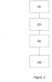
- the method according the invention comprises at least the following steps (see figure 2 ):
- Faults that occur on transmission lines generate transient phenomenon that can be described as traveling waves.
- a physical wave propagation model like traveling waves theory, one can obtain a model for example of the voltage at the line end. This model can be inverted to estimate the initial voltage at the fault location.
- the estimated input voltage can in turn be used to compute subsequent traveling waves that reach the end of the line.
- At least one subsequent traveling wave which has been computed, in particular a second or third traveling *wave reaching a specific location where measurements of voltage and / or current are carried out, can be used then by inversion in order to estimate initial voltage waveform at fault location by using an inverse physical wave propagation model.
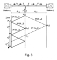
- FIG. 3 A generic transmission line is shown in figure 3 , with stations q and q' and its extremities.
- Figure 3 shows in its lower part a Bewley lattice diagram showing the position and direction of motion of every generated, reflected, and transmitted wave caused by a fault on a transmission line.
- equation 1 must be decoupled through the transformation of phase voltage to modal voltage, using transformation matrix [T V ]. For the sake of simplicity, it is assumed all employed quantities, including measurements, in the rest of the article are in expressed in modal domain.
- Equation 1 The solution of equation 1 consists of the superposition of two waves traveling in opposite directions.
- a pollution fault can for instance be represented as a voltage source connected to the ground, in series with a resistance R f that closes at time t f onto the faulted conductor.
- V init s , R f K f s , R f exp ⁇ t f s s ⁇ bf
- v bf is the phase voltage at the fault location just before the occurrence of the fault
- K f the reflection coefficient from the line to the fault
- the voltage due to subsequent waves can also be computed.
- any wave that travels throughout the grid can be modeled, assuming the characteristics of the grid and the fault parameters are known and that the fault characteristics are available.
- the characteristics of the fault cannot be known in advance.
- the initial fault voltage depends on the lightning current.
- lightning current is stochastic and two different lightning strokes may even have significantly different waveforms, e.g., monopolar or bipolar.
- the forward model of equation 3 can thus not be directly applied as the initial fault voltage V init is unknown.
- Equation 6 assumes the fault distance is known or at least estimated, but equation 6 does not depend on the fault resistance.
- the initial fault voltage can thus be computed regardless of the type of fault and fault resistance.
- a model of the first wave cannot be obtained if the fault location and the initial fault voltage are not known and V m t,1 is set in this case to 0.
- Equation 10 can be interpreted as a model of the additional distortion and attenuation of any wave that reaches the station q after it has been reflected at the fault location. In this specific case the model is directly causal, which simplifies the computations.
- equation 11 gives a model of the total voltage at station q based on the total measured voltage V t .
- equation 10 requires to isolate the n-th TW V c t,n from the total measurements V c t which may not be easily done due to the superposition of all the waves upon a certain time window.
- This model depends explicitly on the fault parameters and in particular on the fault location. As will be shown hereafter, it can also be used to estimate the fault location unless the fault location is for example obtained otherwise and independently for example measurements along the power transmission line.
- US2020116776A1 in the name of the applicant describes a possible optical fault location method.
- t 1 is given by the wave reflected at the remote station.
- Instant t2 is defined as the arrival time of the first wave which is not included in the model. Depending on the grid topology, more or less waves may be included in the model.
- Non-modeled waves thus refer to any wave reaching station q that does not follow the two aforementioned paths. In the grid depicted in Figure 1 and for a fault occurring on line L 14 , this may for instance be a wave traveling towards station 1, then to station 3 and back to station 1. Besides the choice of the modeled waves, the arrival time of the first non-modeled wave depends on the network topology as well as the fault position.
- the network of figure 1 can be represented as an undirected graph with nodes (stations) and weighted edges (lines). The weights account for the length of the lines, or equivalently for the propagation times, as it is assumed the wave speed is constant.
- line L 14 between stations S1and S4 is affected by the fault and is divided into two edges.
- the fault itself is modeled as a node.
- the fault node F can be considered as a sender node, and the station at which the voltage is measured, S1, can be considered as the receiver node.
- the edges are divided into modeled edges (typically the two edges of the faulty line), and non-modeled edges (typically the remaining lines of the grid). Finding t 2 amounts to determine the first shortest path from the starting node to the receiving node that includes a non-modeled edge.
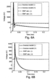
- the arrival times of different TW are displayed in Figure 4A and 4B .
- the first wave, which is not modeled, is referenced FW ( F irst W ave).
- the first modeled wave is referenced FMW ( F irst M odeled W ave), the other modeled waves are dashed lines.
- the first non-modeled wave is marked NMW ( N on M odeled W ave).
- the available observation window is given by the difference between the arrival time of the line MW and the line NMW.
- On Figure 4A only the waves traveling through the faulty line are modeled, i.e., between stations S1 and S4.
- the change of slope in the curve NMW indicates that the paths taken by the first non-modeled wave changes at around 230 km. Before, it is the wave reflected at station S3 that arrives first while after it is the wave that travels towards S2.
- the first modeled wave arrives at the same instant as the first non-modeled wave, which means no observation window would available to estimate the fault location. Knowing that the first non-modeled wave at this distance is due to the reflection at station 3, the model can be extended to account for such reflections.
- the results are presented in Figure 4B .
- the former line limiting the observation window for fault distances between ranging from 0 to 220 km is now dashed as it has been included in the model.
- L 14 For a relay monitoring a given line, here L 14 , it should be ensured that for any possible fault, the observation window is always limited to modeled waves.
- a specific location may be anywhere in the power transmission and/ or distribution system but preferentially a specific location is at an end of a current transmission line like for example L 12 , L 13 , L 23 and/ or a relay and/or a breaker module and/ or a station like station 1, 2, 3 or 4.
- the above described method is for example started upon detection of an unusual behavior with respect to a nominal functioning of the electrical power transmission and/or distribution system 100.
- An unusual behavior comprising among others a voltage drop, a current increase, a crossing of a threshold or a combination of thereof.
- the distance between said specific location and the fault location may be obtained independently from the measurement of voltage and/or current evolution at said specific location. For example ...(please give example).
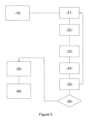
- the distance between said specific location and the fault location is obtained through at least following steps:
- a verification is carried out in order to determine that the obtained fault location belongs to a predefined validity domain.
- One of the last steps of the above described method comprises the control / activation of protection actions.
- This control of protection actions is carried out in function of the fault classification which comprises for example activation of protection circuits in the said electrical power transmission and/or distribution system 100.
- the fault classification comprises for example one or several classes like a class for pollution/vegetation faults, a class for direct lightning strikes causing a flashover and a class for direct lightning strikes causing disturbance.
- the fault classification may be carried out by machine learning, in particular in using "support-vector machines” (SVMs, also support-vector networks) which are supervised learning models with associated learning algorithms that analyze data for classification and regression analysis.
- SVM can perform linear classification as well as a non-linear classification using what is called the kernel trick, implicitly mapping their inputs into high-dimensional feature spaces. Both approaches were used for classification and for 4 different classes comprising "pollution fault causing pole to ground”, “lightning strike causing disturbance”, “lightning strike causing negative to ground” and “lightning strike causing positive to negative to ground”, a 100% accuracy has been achieved.
- lightning strikes causing disturbance with no need of protection activation account for the majority of faults in particular an aerial power transmission and distribution system 100.
- the above described method may be carried out as a transient-based diagnostic method for classifying disturbance events in an electric power transmission and/ or distribution system having at least one current transmission line. It comprises all the steps as described above except for control step 40.
- the over-voltage at the stroke tower causes the flashover of the insulator string, inducing a fault.
- the magnitude of the lightning current is smaller and the insulation withstands the overvoltage, causing the lightning current to propagate as a disturbance throughout the stroke conductor without causing any fault and thus without the need to activate a protection circuit.
- the modeled initial voltage can be compared to the output of EMT simulation for both events as shown in figures 6A and 6B.
- Figures 6A and 6B show the modeled initial voltage following a direct lightning strike on line L 12 which causes a pole to ground fault ( figure 6A ) and a disturbance ( figure 6B ), compared with EMT simulation.
- the overvoltage on the negative pole of about is well represented as well as the tail of the waveform.
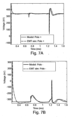
- the model of the subsequent waves arriving at station 1 is depicted in Figures 7A and 7B (pole to ground fault ( figure 7A ) and a disturbance ( figure 7B ) and compared with EMT simulation.
- the first measured wave is used to determine the initial fault wave, it cannot be employed to model the station voltage, at the output of the model is arbitrarily set to 0 until the second wave arrives.
- Figure 8B shows a graph representing a comparison of the modeled initial voltage waveform at the fault location with EMT simulation following a lightning strike on the positive pole
- Figure 9A positive pole - figure 9B : negative pole.
- Figures 9A and 9B show that a subsequent, in particular a second travelling wave can be simulated by the proposed method with a quite good precision.
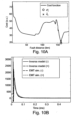
- the estimated initial fault voltage is compared with EMT simulation in Figure 10B , where the convergence of the two pole voltages indicates a pole to pole to ground fault has occurred.
- the model of the subsequent waves is compared with the EMT simulation in Figure 11A and 11B and shows a quite good match that is sufficient for fault classification and taking the necessary protection actions.
- the here described method allows upon some measurements to estimate the initial waveform at fault location and that to classify the faults and to take in function of the classification result the necessary protection actions if needed. Therefore, operation of a power distribution and transmission can be optimized and in particular interruptions due to mere disturbances can be avoided.
Landscapes
- Engineering & Computer Science (AREA)
- Theoretical Computer Science (AREA)
- Locating Faults (AREA)
Priority Applications (1)
| Application Number | Priority Date | Filing Date | Title |
|---|---|---|---|
| EP22315295.0A EP4366104A1 (de) | 2022-11-02 | 2022-11-02 | Übergangsbasiertes verfahren zur steuerung von schutzmassnahmen in einem stromübertragungs- und/oder verteilungssystem |
Applications Claiming Priority (1)
| Application Number | Priority Date | Filing Date | Title |
|---|---|---|---|
| EP22315295.0A EP4366104A1 (de) | 2022-11-02 | 2022-11-02 | Übergangsbasiertes verfahren zur steuerung von schutzmassnahmen in einem stromübertragungs- und/oder verteilungssystem |
Publications (1)
| Publication Number | Publication Date |
|---|---|
| EP4366104A1 true EP4366104A1 (de) | 2024-05-08 |
Family
ID=84535995
Family Applications (1)
| Application Number | Title | Priority Date | Filing Date |
|---|---|---|---|
| EP22315295.0A Pending EP4366104A1 (de) | 2022-11-02 | 2022-11-02 | Übergangsbasiertes verfahren zur steuerung von schutzmassnahmen in einem stromübertragungs- und/oder verteilungssystem |
Country Status (1)
| Country | Link |
|---|---|
| EP (1) | EP4366104A1 (de) |
Cited By (4)
| Publication number | Priority date | Publication date | Assignee | Title |
|---|---|---|---|---|
| CN118425687A (zh) * | 2024-05-27 | 2024-08-02 | 广东电网有限责任公司广州供电局 | 基于行波特征的输电线缆故障监测方法及系统 |
| CN119438761A (zh) * | 2024-11-06 | 2025-02-14 | 西安理工大学 | 基于电压行波分布特征的柔直输电线路雷击干扰识别方法 |
| CN120389518A (zh) * | 2025-04-27 | 2025-07-29 | 四川蜀道新制式轨道集团有限责任公司 | 一种基于数据分析的电力设备运维监控方法及系统 |
| CN122043144A (zh) * | 2026-04-17 | 2026-05-15 | 江苏海立普电力科技有限公司 | 行波数据处理系统及行波数据处理方法 |
Citations (5)
| Publication number | Priority date | Publication date | Assignee | Title |
|---|---|---|---|---|
| EP3062185A1 (de) | 2015-02-27 | 2016-08-31 | Siemens Aktiengesellschaft | Modelbasiertes schutzsystem für elektrische systeme |
| US9465067B2 (en) | 2013-04-08 | 2016-10-11 | ECOLE POLYTECHNIQUE FéDéRALE DE LAUSANNE | Efficient method based on the electromagnetic time reversal to locate faults in power network |
| WO2019232595A1 (en) * | 2018-06-07 | 2019-12-12 | Federation University Australia | A method of estimating the location of a fault on an electrical distribution network and an associated system |
| US20200116776A1 (en) | 2017-06-06 | 2020-04-16 | Supergrid Institute | Device for Detecting a Short Circuit, Protection Device and Associated Method for a High-Voltage Dc Network |
| CN111404130A (zh) * | 2020-04-14 | 2020-07-10 | 国网内蒙古东部电力有限公司赤峰供电公司 | 基于快速开关的新型配电网故障检测方法及故障自愈系统 |
-
2022
- 2022-11-02 EP EP22315295.0A patent/EP4366104A1/de active Pending
Patent Citations (5)
| Publication number | Priority date | Publication date | Assignee | Title |
|---|---|---|---|---|
| US9465067B2 (en) | 2013-04-08 | 2016-10-11 | ECOLE POLYTECHNIQUE FéDéRALE DE LAUSANNE | Efficient method based on the electromagnetic time reversal to locate faults in power network |
| EP3062185A1 (de) | 2015-02-27 | 2016-08-31 | Siemens Aktiengesellschaft | Modelbasiertes schutzsystem für elektrische systeme |
| US20200116776A1 (en) | 2017-06-06 | 2020-04-16 | Supergrid Institute | Device for Detecting a Short Circuit, Protection Device and Associated Method for a High-Voltage Dc Network |
| WO2019232595A1 (en) * | 2018-06-07 | 2019-12-12 | Federation University Australia | A method of estimating the location of a fault on an electrical distribution network and an associated system |
| CN111404130A (zh) * | 2020-04-14 | 2020-07-10 | 国网内蒙古东部电力有限公司赤峰供电公司 | 基于快速开关的新型配电网故障检测方法及故障自愈系统 |
Non-Patent Citations (1)
| Title |
|---|
| VERRAX PAUL ET AL: "Fast Fault Identification in Bipolar HVDC Grids: A Fault Parameter Estimation Approach", IEEE TRANSACTIONS ON POWER DELIVERY, IEEE SERVICE CENTER, NEW YORK, NY, US, vol. 37, no. 1, 4 February 2021 (2021-02-04), pages 258 - 267, XP011898537, ISSN: 0885-8977, [retrieved on 20220120], DOI: 10.1109/TPWRD.2021.3056876 * |
Cited By (4)
| Publication number | Priority date | Publication date | Assignee | Title |
|---|---|---|---|---|
| CN118425687A (zh) * | 2024-05-27 | 2024-08-02 | 广东电网有限责任公司广州供电局 | 基于行波特征的输电线缆故障监测方法及系统 |
| CN119438761A (zh) * | 2024-11-06 | 2025-02-14 | 西安理工大学 | 基于电压行波分布特征的柔直输电线路雷击干扰识别方法 |
| CN120389518A (zh) * | 2025-04-27 | 2025-07-29 | 四川蜀道新制式轨道集团有限责任公司 | 一种基于数据分析的电力设备运维监控方法及系统 |
| CN122043144A (zh) * | 2026-04-17 | 2026-05-15 | 江苏海立普电力科技有限公司 | 行波数据处理系统及行波数据处理方法 |
Similar Documents
| Publication | Publication Date | Title |
|---|---|---|
| US12117479B2 (en) | Transient based method for identifying faults in a high / medium voltage electric power transmission system | |
| Lopes et al. | Real-time traveling-wave-based fault location using two-terminal unsynchronized data | |
| Sun et al. | Backup protection of multi-terminal HVDC grids based on quickest change detection | |
| Razzaghi et al. | Fault location in multi-terminal HVDC networks based on electromagnetic time reversal with limited time reversal window | |
| Mishra et al. | FDOST-based fault classification scheme for fixed series compensated transmission system | |
| Leite et al. | Closed-form solution for traveling wave-based fault location on non-homogeneous lines | |
| KR101099788B1 (ko) | 송전선로 섬락 고장 판별 장치 및 방법 | |
| Fedorov et al. | Theory of single-end traveling wave fault location | |
| Verrax et al. | Fast fault identification in bipolar HVDC grids: a fault parameter estimation approach | |
| CN104316833A (zh) | 一种中压配电网故障行波选线方法 | |
| Ngwenyama et al. | Traveling wave fault location detection technique for high voltage transmission lines | |
| Song et al. | Fault detection and protection in a meshed MMCHVDC grid based on bus-voltage change rate and fault component current | |
| US10267842B2 (en) | Method for identifying a faulted DC power transmission medium in a multi-terminal DC electrical network | |
| Razzaghi et al. | Electromagnetic time reversal applied to fault location in power networks | |
| Han et al. | Fault location on a mixed overhead and underground transmission feeder using a multiple-zone quadrilateral impedance relay and a double-ended travelling wave fault locator | |
| Kafal et al. | A review on the application of the time reversal theory to wire network and power system diagnosis | |
| Ray et al. | Hybrid technique for fault location of a distribution line | |
| Costa et al. | Fault-induced transient analysis for realtime fault detection and location in transmission lines | |
| Radwan et al. | A novel double-ended fault location identification scheme for multi-terminal HVDC grids based on Hilbert-Huang transform | |
| Fluty et al. | Electric transmission fault location techniques using traveling wave method and discrete wavelet transform | |
| Abdullah | Busbar protection using a wavelet based ANN | |
| Prabhakar | Distance protection schemes in distributed generation connected transmission system combined with machine learning | |
| US12235308B2 (en) | Power-line event location systems and methods | |
| Auran et al. | A novel pole-to-ground fault detection algorithm for meshed HVDC grids with half-bridge MMC converters and full recourse to DC circuit breakers | |
| Marvasti et al. | A Pilot protection scheme for HVDC transmission lines based on simultaneous existence of forward and backward voltage travelling waves |
Legal Events
| Date | Code | Title | Description |
|---|---|---|---|
| PUAI | Public reference made under article 153(3) epc to a published international application that has entered the european phase |
Free format text: ORIGINAL CODE: 0009012 |
|
| STAA | Information on the status of an ep patent application or granted ep patent |
Free format text: STATUS: THE APPLICATION HAS BEEN PUBLISHED |
|
| AK | Designated contracting states |
Kind code of ref document: A1 Designated state(s): AL AT BE BG CH CY CZ DE DK EE ES FI FR GB GR HR HU IE IS IT LI LT LU LV MC ME MK MT NL NO PL PT RO RS SE SI SK SM TR |
|
| STAA | Information on the status of an ep patent application or granted ep patent |
Free format text: STATUS: REQUEST FOR EXAMINATION WAS MADE |
|
| 17P | Request for examination filed |
Effective date: 20241105 |
|
| RBV | Designated contracting states (corrected) |
Designated state(s): AL AT BE BG CH CY CZ DE DK EE ES FI FR GB GR HR HU IE IS IT LI LT LU LV MC ME MK MT NL NO PL PT RO RS SE SI SK SM TR |