EP4366027A1 - Battery pack - Google Patents
Battery pack Download PDFInfo
- Publication number
- EP4366027A1 EP4366027A1 EP22846129.9A EP22846129A EP4366027A1 EP 4366027 A1 EP4366027 A1 EP 4366027A1 EP 22846129 A EP22846129 A EP 22846129A EP 4366027 A1 EP4366027 A1 EP 4366027A1
- Authority
- EP
- European Patent Office
- Prior art keywords
- control module
- battery
- mounting portion
- disposed
- module frame
- Prior art date
- Legal status (The legal status is an assumption and is not a legal conclusion. Google has not performed a legal analysis and makes no representation as to the accuracy of the status listed.)
- Pending
Links
- 238000003780 insertion Methods 0.000 claims description 18
- 230000037431 insertion Effects 0.000 claims description 18
- 238000005192 partition Methods 0.000 abstract description 10
- 238000004519 manufacturing process Methods 0.000 abstract description 7
- 238000000034 method Methods 0.000 description 6
- 239000003292 glue Substances 0.000 description 3
- PXHVJJICTQNCMI-UHFFFAOYSA-N Nickel Chemical compound [Ni] PXHVJJICTQNCMI-UHFFFAOYSA-N 0.000 description 2
- 230000000694 effects Effects 0.000 description 2
- 239000000047 product Substances 0.000 description 2
- 238000004904 shortening Methods 0.000 description 2
- UFHFLCQGNIYNRP-UHFFFAOYSA-N Hydrogen Chemical compound [H][H] UFHFLCQGNIYNRP-UHFFFAOYSA-N 0.000 description 1
- WHXSMMKQMYFTQS-UHFFFAOYSA-N Lithium Chemical compound [Li] WHXSMMKQMYFTQS-UHFFFAOYSA-N 0.000 description 1
- HBBGRARXTFLTSG-UHFFFAOYSA-N Lithium ion Chemical compound [Li+] HBBGRARXTFLTSG-UHFFFAOYSA-N 0.000 description 1
- 239000006227 byproduct Substances 0.000 description 1
- OJIJEKBXJYRIBZ-UHFFFAOYSA-N cadmium nickel Chemical compound [Ni].[Cd] OJIJEKBXJYRIBZ-UHFFFAOYSA-N 0.000 description 1
- 230000001934 delay Effects 0.000 description 1
- 230000006866 deterioration Effects 0.000 description 1
- 239000013013 elastic material Substances 0.000 description 1
- 238000005516 engineering process Methods 0.000 description 1
- 238000004880 explosion Methods 0.000 description 1
- 239000002803 fossil fuel Substances 0.000 description 1
- 229910052739 hydrogen Inorganic materials 0.000 description 1
- 239000001257 hydrogen Substances 0.000 description 1
- 229910052744 lithium Inorganic materials 0.000 description 1
- 229910001416 lithium ion Inorganic materials 0.000 description 1
- 238000005259 measurement Methods 0.000 description 1
- 229910052759 nickel Inorganic materials 0.000 description 1
- QELJHCBNGDEXLD-UHFFFAOYSA-N nickel zinc Chemical compound [Ni].[Zn] QELJHCBNGDEXLD-UHFFFAOYSA-N 0.000 description 1
- 229920000642 polymer Polymers 0.000 description 1
- 238000005476 soldering Methods 0.000 description 1
- 238000003892 spreading Methods 0.000 description 1
- 230000001629 suppression Effects 0.000 description 1
- 238000003466 welding Methods 0.000 description 1
Images


Classifications
-
- H—ELECTRICITY
- H01—ELECTRIC ELEMENTS
- H01M—PROCESSES OR MEANS, e.g. BATTERIES, FOR THE DIRECT CONVERSION OF CHEMICAL ENERGY INTO ELECTRICAL ENERGY
- H01M10/00—Secondary cells; Manufacture thereof
- H01M10/42—Methods or arrangements for servicing or maintenance of secondary cells or secondary half-cells
- H01M10/48—Accumulators combined with arrangements for measuring, testing or indicating the condition of cells, e.g. the level or density of the electrolyte
-
- H—ELECTRICITY
- H01—ELECTRIC ELEMENTS
- H01M—PROCESSES OR MEANS, e.g. BATTERIES, FOR THE DIRECT CONVERSION OF CHEMICAL ENERGY INTO ELECTRICAL ENERGY
- H01M10/00—Secondary cells; Manufacture thereof
- H01M10/42—Methods or arrangements for servicing or maintenance of secondary cells or secondary half-cells
- H01M10/425—Structural combination with electronic components, e.g. electronic circuits integrated to the outside of the casing
-
- H—ELECTRICITY
- H01—ELECTRIC ELEMENTS
- H01M—PROCESSES OR MEANS, e.g. BATTERIES, FOR THE DIRECT CONVERSION OF CHEMICAL ENERGY INTO ELECTRICAL ENERGY
- H01M10/00—Secondary cells; Manufacture thereof
- H01M10/42—Methods or arrangements for servicing or maintenance of secondary cells or secondary half-cells
- H01M10/48—Accumulators combined with arrangements for measuring, testing or indicating the condition of cells, e.g. the level or density of the electrolyte
- H01M10/482—Accumulators combined with arrangements for measuring, testing or indicating the condition of cells, e.g. the level or density of the electrolyte for several batteries or cells simultaneously or sequentially
-
- H—ELECTRICITY
- H01—ELECTRIC ELEMENTS
- H01M—PROCESSES OR MEANS, e.g. BATTERIES, FOR THE DIRECT CONVERSION OF CHEMICAL ENERGY INTO ELECTRICAL ENERGY
- H01M10/00—Secondary cells; Manufacture thereof
- H01M10/42—Methods or arrangements for servicing or maintenance of secondary cells or secondary half-cells
- H01M10/48—Accumulators combined with arrangements for measuring, testing or indicating the condition of cells, e.g. the level or density of the electrolyte
- H01M10/486—Accumulators combined with arrangements for measuring, testing or indicating the condition of cells, e.g. the level or density of the electrolyte for measuring temperature
-
- H—ELECTRICITY
- H01—ELECTRIC ELEMENTS
- H01M—PROCESSES OR MEANS, e.g. BATTERIES, FOR THE DIRECT CONVERSION OF CHEMICAL ENERGY INTO ELECTRICAL ENERGY
- H01M50/00—Constructional details or processes of manufacture of the non-active parts of electrochemical cells other than fuel cells, e.g. hybrid cells
- H01M50/20—Mountings; Secondary casings or frames; Racks, modules or packs; Suspension devices; Shock absorbers; Transport or carrying devices; Holders
- H01M50/284—Mountings; Secondary casings or frames; Racks, modules or packs; Suspension devices; Shock absorbers; Transport or carrying devices; Holders with incorporated circuit boards, e.g. printed circuit boards [PCB]
- H01M50/287—Fixing of circuit boards to lids or covers
-
- H—ELECTRICITY
- H01—ELECTRIC ELEMENTS
- H01M—PROCESSES OR MEANS, e.g. BATTERIES, FOR THE DIRECT CONVERSION OF CHEMICAL ENERGY INTO ELECTRICAL ENERGY
- H01M10/00—Secondary cells; Manufacture thereof
- H01M10/42—Methods or arrangements for servicing or maintenance of secondary cells or secondary half-cells
- H01M10/425—Structural combination with electronic components, e.g. electronic circuits integrated to the outside of the casing
- H01M2010/4271—Battery management systems including electronic circuits, e.g. control of current or voltage to keep battery in healthy state, cell balancing
-
- Y—GENERAL TAGGING OF NEW TECHNOLOGICAL DEVELOPMENTS; GENERAL TAGGING OF CROSS-SECTIONAL TECHNOLOGIES SPANNING OVER SEVERAL SECTIONS OF THE IPC; TECHNICAL SUBJECTS COVERED BY FORMER USPC CROSS-REFERENCE ART COLLECTIONS [XRACs] AND DIGESTS
- Y02—TECHNOLOGIES OR APPLICATIONS FOR MITIGATION OR ADAPTATION AGAINST CLIMATE CHANGE
- Y02E—REDUCTION OF GREENHOUSE GAS [GHG] EMISSIONS, RELATED TO ENERGY GENERATION, TRANSMISSION OR DISTRIBUTION
- Y02E60/00—Enabling technologies; Technologies with a potential or indirect contribution to GHG emissions mitigation
- Y02E60/10—Energy storage using batteries
Definitions
- the present disclosure relates to a battery pack and more particularly to a battery pack which includes a battery module frame on which a control module mounting portion is formed on one outer side thereof and a control module which is coupled to the control module mounting portion.
- a secondary battery which can be easily applied depending on a product group and has electrical characteristics such as high energy density is being generally used not only in portable devices but also in an electric vehicle (EV) or a hybrid electric vehicle (HEV) which is driven by an electrical drive source.
- EV electric vehicle
- HEV hybrid electric vehicle
- the secondary battery not only has a primary advantage of being able to significantly reduce the use of fossil fuels, but also does never generate any by-products due to energy use. In this respect, the secondary battery is attracting attention as a new energy source for improving eco-friendliness and energy efficiency.
- the type of the secondary battery currently widely used includes a lithium-ion battery, a lithium polymer battery, a nickel cadmium battery, a nickel hydrogen battery, and a nickel zinc battery.
- the operating voltage of such a unit secondary battery cell is approximately 2.5 V to 4.5 V. Therefore, when an output voltage higher than the operating voltage is required, a battery pack is formed by connecting in series a plurality of battery cells. Also, the battery pack may also be formed by connecting numbers of battery cells in parallel depending on a charge/discharge capacity required for the battery pack. Accordingly, the number of battery cells included in the battery pack may be variously set depending on the required output voltage or charge/discharge capacity.
- the battery pack including a plurality of cells blocks overcurrent in various ways to obtain safety in use. For example, when cell temperature sensed by a thermistor exceeds a standard value, a BMS module blocks the current flowing through the battery pack.
- the thermistor for measuring current cell temperature is generally attached to the battery cell by means of glue or a fixing tape in a manufacturing process of the battery pack.
- glue glue
- the thermistor is attached by using the glue, there is a possibility that the thermistor is separated from the battery cell during the process before the glue is cured.
- the thermistor is attached by using the tape, there is a possibility that the thermistor is separated from the battery cell not only during the process but also during use of the product.
- the thermistor attached to the battery cell is separated from a designed attachment position, it is difficult to accurately sense the battery cell temperature, so that it is not possible to block the overcurrent flowing through the battery pack even when the battery cell temperature rises due to short circuit. This can lead to ignition/explosion of the battery pack.
- a battery pack that has not only a structure capable of securely fixing the thermistor in a manufacturing process of the battery pack, but also has a structure that prevents the thermistor from being separated from the mounted position during use of the battery pack.
- the embodiment of the present disclosure is designed to overcome the above problems of related technical fields and the purpose of the present disclosure is to provide a battery pack which is able to improve assemblability of a thermistor when coupled to a battery module and to shorten the manufacturing process by forming a battery management system module-integrated thermistor, thereby more accurately measuring battery cell temperature.
- One embodiment is a battery pack including: a battery module configured to include a battery module frame including a cell mounting portion formed therein on which a plurality of battery cells is disposed and a control module mounting portion formed on one outer side surface thereof; a control module configured to be coupled to the control module mounting portion and control operations of the battery cell; and a thermistor unit configured to be connected to the control module, to come into contact with the battery cell, and to measure a temperature of the battery cell.
- the control module may include: a control module frame configured to be coupled to the control module mounting portion; a main circuit board configured to be disposed on the control module frame; and a sub-circuit board configured to be disposed on the control module frame and to be electrically connected to the main circuit board.
- One or more cut portions may be formed by being cut in an inward direction of the cell mounting portion.
- One or more protrusions may be formed at positions corresponding to the cut portions in the control module frame in such a way as to protrude toward the cut portions.
- the sub-circuit board may be formed with a circuit extension part which extends to the protrusion.
- the thermistor unit may be electrically connected to the circuit extension part is disposed at an end of the protrusion. When the protrusion is inserted into the cut portion, the thermistor unit may come into contact with the battery cell.
- the thermistor unit may include: a thermistor chip configured to be disposed on an end surface of the protrusion; and a heat conduction pad configured to be disposed on the end surface of the protrusion and to surround the thermistor chip.
- the battery pack may include: an insertion portion configured to be disposed in both inner sides of the cut portion and to protrude in a direction facing each other; and an insertion protrusion configured to be disposed on both sides of the protrusion and to be inserted into the insertion portion.
- the battery module may further include: a support block configured to be arranged to protrude outward from the control module mounting portion and has a fastening hole formed therein; a stepped portion configured to be formed inward at both ends of the control module mounting portion and to allow the control module frame to be inserted thereinto; and a fitting piece configured to be formed to protrude outward from the control module mounting portion.
- the control module may include: a piece contact portion configured to be formed in the control module frame, to allow the support block to contact, to support the control module frame, and to have a through hole that is bolted to the fastening hole; and a fitting recess configured to be formed in the control module frame, to allow the fitting piece to be inserted thereinto, and to support the control module frame.
- the thermistor is integrated into the battery management system module, it is possible to improve assemblability of the thermistor when coupled to a battery module and to shorten the manufacturing process.
- a battery pack 100 of the present disclosure may include a battery module 300, a control module 200, and a thermistor unit 250.
- the battery module 300 may include a battery module frame 310, a partition wall 340, and a bus bar 500.
- the battery module frame 310 may form an overall appearance of the battery module 300 and may include a cell mounting portion 330 formed therein on which a plurality of battery cells 400 can be disposed. Referring to FIGS. 5 and 6 , it can be seen that the plurality of battery cells 400 is arranged within the battery module frame 310 in a plurality of columns and rows.
- the cell mounting portion 330 is formed within the battery module frame 310 and protects the plurality of battery cells 400 from external impact.
- a control module mounting portion 320 may be formed on one outer side surface of the battery module frame 310.
- the control module mounting portion 320 may include a support block 321, a stepped portion 322, a fitting piece 323, and cut portions 325 and 326.
- the support block 321 may be arranged to protrude outward from the control module mounting portion 320 and may have a fastening hole 321a formed in a central portion thereof. A thread may be processed within the fastening hole 321a such that a bolt can be coupled thereto.
- the support block 321 may have a cross shape, but is not limited thereto.
- the stepped portion 322 may be formed inward at both ends of the control module mounting portion 320.
- the control module 200 may be inserted into the inside of the stepped portion 322.
- the fitting piece 323 may be disposed below the support block 321 in the control module mounting portion 320 and may be formed to protrude outward.
- the fitting piece 323 has a quadrangular shape having one open side, but is not limited thereto.
- the cut portions 325 and 326 may be formed in an upper portion of the control module mounting portion 320 and may be formed by being cut in an inward direction of the cell mounting portion 330.
- One or more cut portions 325 and 326 may be formed, and in the embodiment of the present disclosure, two cut portions may be formed.
- the temperature of the battery cell 400 is measured by inserting the thermistor unit 250 into two points and contacting the thermistor unit 250 with the battery cell 400, thereby improving the accuracy of an average temperature value of the battery cell 400.
- the temperature of the battery cell 400 may be measured by forming the cut portions 325 and 326 in more locations and by inserting and contacting the thermistor unit 250 with the battery cell. In this case, the accuracy of the average temperature value of the battery cell 400 can be further improved.
- the partition wall 340 is formed on the battery module frame 310 and may separate the plurality of battery cells 400 from each other. Even if a specific battery cell 400 is degraded and spark or fire occurs locally, the partition wall 340 blocks the spark or fire or delays the spread of the spark or fire, thereby preventing the spark or fire from spreading to other battery cells 400 or delaying the spread. This can prevent or delay the occurrence of deterioration of the entire battery module 300. Ultimately, when the partition wall is installed in an electric vehicle, the partition wall allows a driver to have evacuation time and fire suppression time.
- the bus bar 500 may be disposed between the partition walls 340 over the battery module frame 310 and may be electrically connected to the plurality of battery cells 400. As is known, the bus bar 500 allows the plurality of battery cells 400 to be connected in parallel or in series as needed.
- control module 200 may be coupled to the control module mounting portion 320 and may control the operation of the battery cell 400.
- control module 200 may be a battery management system (BMS) module.
- BMS battery management system
- the control module 200 may include a control module frame 210, a main circuit board 230, a sub-circuit board 220, circuit extension parts 221 and 222, protrusions 215 and 216, a piece contact portion 211a, and a fitting recess 212.
- the control module frame 210 may form an overall appearance of the control module 200 and may be coupled to the control module mounting portion 320.
- the main circuit board 230 may be disposed in a central portion of the control module frame 210. Electronic components capable of controlling the battery cell 400 may be electrically connected and disposed on the main circuit board 230. In the embodiment of the present disclosure, the main circuit board 230 may be a BMS printed circuit board.
- the sub-circuit board 220 may be electrically connected to the main circuit board 230 and may extend to a top of the control module frame 210.
- the sub-circuit board 220 is arranged to extend to the top of the control module frame 210.
- the sub-circuit board 220 may be a flexible printed circuit board (FPCB).
- the sub-circuit board 220 is disposed up to the top of the control module frame 210 is to extend the electrical circuit connection to the protrusions 215 and 216.
- the protrusions 215 and 216 may be formed at positions corresponding to the cut portions 325 and 326 in such a way as to protrude from the top of the control module frame 210 toward the cut portions 325 and 326.
- sub-circuit board 220 may be formed with the circuit extension parts 221 and 222 which extend to the protrusions 215 and 216.
- the thermistor unit 250 may be disposed at the ends of the protrusions 215 and 216 and may be electrically connected to the circuit extension parts 221 and 222.
- the sub-circuit board 220 is disposed up to the top of the control module frame 210, and the circuit extension parts 221 and 222 are formed on the sub-circuit board 220 and are disposed up to the protrusions 215 and 216.
- an electrical signal is transmitted to the thermistor unit 250 integrally coupled to the control module 200.
- the control module 200 is just assembled to the battery module 300, the thermistor unit 250 comes into contact with the battery cell 400 and thus the temperature of the battery cell 400 can be measured. Accordingly, there is no requirement for a separate attachment process of welding the thermistor unit 250 to the battery cell 400.
- the piece contact portion 211a may be formed on the upper portion of the control module frame 210.
- the support block 321 may come into contact with the piece contact portion 211a.
- the piece contact portion 211a may support an upper position of the control module frame 210.
- a through hole 211 that can be bolted to the fastening hole 321a may be formed in the central portion of the piece contact portion 211a.
- the fitting recess 212 may be formed in a lower portion of the control module frame 210.
- a fitting block may be inserted into the fitting recess 212.
- the fitting recess 212 may support a lower position of the control module frame 210.
- the thermistor unit 250 may be connected to the control module 200, may come into contact with the battery cell 400, and may measure the temperature of the battery cell 400.
- the thermistor unit 250 may include a thermistor chip 251 and a heat conduction pad 253.
- the thermistor chip 251 may be disposed on end surfaces of the protrusions 215 and 216.
- the thermistor chip used in the present disclosure can perform a sensor function which converts a thermal signal into an electrical signal by using resistance changes according to temperature.
- the heat conduction pad 253 may be disposed on the end surfaces of the protrusions 215 and 216 and may surround the thermistor chip 251. That is, the thermistor chip 251 does not come into direct contact with the battery cell 400, and the thermal conductive pad 253 may bring into contact with the battery cell 400 and the heat of the battery cell 400 may be conducted through the heat conduction pad and may be transmitted to the thermistor chip 251.
- the heat conduction pad 253 may be made of an elastic material, and accordingly, when the heat conduction pad 253 is deformed in shape by contact with the battery cell 400, the heat conduction pad 253 can maintain the contact state and eliminate gaps in the battery cell 400. Accordingly, the temperature of the battery cell 400 can be accurately transmitted to the thermistor chip 251.
- insertion portions 341 are disposed in both inner sides of the cut portion 325.
- the insertion portions 341 protrude from both inner sides of the cut portion 325 in a direction facing each other.
- a groove is formed in the insertion portion 341.
- insertion protrusions 217 are disposed on both sides of the protrusion 215. As the insertion protrusion 217 is inserted into the insertion portion 341, the position of the protrusion 215 is fixed within the cut portion 325.
- the heat conduction pad 253 can be stably maintained in contact with the surface of the battery cell 400.
- FIG. 5 is a partial plan view showing a state before the thermistor unit 250 comes into contact with the battery cell 400 when the battery module 300 and the control module 200 are assembled in the battery pack 100 of the embodiment of the present disclosure.
- FIG. 6 is a partial plan view showing a state after the thermistor unit 250 comes into contact with the battery cell 400 when the battery module 300 and the control module 200 are assembled in the battery pack 100 of the embodiment of the present disclosure.
- the partition wall 340 and the bus bar 500 are disposed on the battery module frame 310, and the cut portion 325 is formed in a portion leading from a portion of the partition wall 340 to the control module mounting portion 320.
- a pair of insertion portions 341 is formed on both inner sides of the cut portion 325.
- the circuit extension part 221 of the flexible printed circuit board extends to the protrusion 215 on the upper portion of the control module frame 210, and the heat conduction pad 253 is disposed on the end surface of the protrusion 215.
- the thermistor chip 251 is built into the heat conduction pad 253.
- a pair of insertion protrusions 217 is formed on both sides of the protrusion 215.
- control module 200 is assembled to the control module mounting portion 320 of the battery module frame 310. That is, the control module 200 is pushed into the stepped portion 322 of the control module mounting portion 320, and then the through hole 211 and the fastening hole 321a are bolted.
- the protrusion 215 is further inserted into the cut portion 325, and the heat conduction pad 253 comes into contact with the surface of the battery cell 400.
- the position of the protrusion 215 is fixed within the cut portion 325.
- the thermistor unit 250 automatically comes into contact with the battery cell 400, thereby measuring the temperature of the battery cell 400.
- the control module 200 and the thermistor unit 250 are integrated with each other. Therefore, when the control module 200 and the battery module 300 are coupled, the thermistor unit 250 automatically comes into contact with the battery cell 400. Accordingly, ultimately, there are technical effects of improving assemblability of the battery pack 100 and of shortening the manufacturing process. Also, it is possible to increase the operational stability of the thermistor unit 250 compared to a conventional soldering method and to measure the temperature of the battery cell 400 more accurately.
Landscapes
- Chemical & Material Sciences (AREA)
- Chemical Kinetics & Catalysis (AREA)
- Electrochemistry (AREA)
- General Chemical & Material Sciences (AREA)
- Engineering & Computer Science (AREA)
- Manufacturing & Machinery (AREA)
- Microelectronics & Electronic Packaging (AREA)
- Battery Mounting, Suspending (AREA)
Abstract
The present disclosure relates to a battery pack including: a battery module configured to include a battery module frame including a cell mounting portion formed therein on which a plurality of battery cells is disposed and a control module mounting portion formed on one outer side surface thereof, a partition wall configured to be formed on the battery module frame and to separate the plurality of battery cells, and a bus bar configured to be disposed between the partition walls over the battery module frame and to be electrically connected to the plurality of battery cells; a control module configured to be coupled to the control module mounting portion and control operations of the battery cell; and a thermistor unit configured to be connected to the control module, to come into contact with the battery cell, and to measure a temperature of the battery cell. According to the embodiment of the present disclosure, a control module-integrated thermistor is formed, so that assemblability of the thermistor can be improved and the manufacturing process can be shortened, thereby more accurately measuring battery cell temperature.
Description
- The present disclosure relates to a battery pack and more particularly to a battery pack which includes a battery module frame on which a control module mounting portion is formed on one outer side thereof and a control module which is coupled to the control module mounting portion.
- A secondary battery which can be easily applied depending on a product group and has electrical characteristics such as high energy density is being generally used not only in portable devices but also in an electric vehicle (EV) or a hybrid electric vehicle (HEV) which is driven by an electrical drive source.
- The secondary battery not only has a primary advantage of being able to significantly reduce the use of fossil fuels, but also does never generate any by-products due to energy use. In this respect, the secondary battery is attracting attention as a new energy source for improving eco-friendliness and energy efficiency.
- The type of the secondary battery currently widely used includes a lithium-ion battery, a lithium polymer battery, a nickel cadmium battery, a nickel hydrogen battery, and a nickel zinc battery.
- The operating voltage of such a unit secondary battery cell, that is, a unit battery cell, is approximately 2.5 V to 4.5 V. Therefore, when an output voltage higher than the operating voltage is required, a battery pack is formed by connecting in series a plurality of battery cells. Also, the battery pack may also be formed by connecting numbers of battery cells in parallel depending on a charge/discharge capacity required for the battery pack. Accordingly, the number of battery cells included in the battery pack may be variously set depending on the required output voltage or charge/discharge capacity.
- As such, the battery pack including a plurality of cells blocks overcurrent in various ways to obtain safety in use. For example, when cell temperature sensed by a thermistor exceeds a standard value, a BMS module blocks the current flowing through the battery pack.
- The thermistor for measuring current cell temperature is generally attached to the battery cell by means of glue or a fixing tape in a manufacturing process of the battery pack. However, it is not easy to attach the thermistor to a correct position. Also, when the thermistor is attached by using the glue, there is a possibility that the thermistor is separated from the battery cell during the process before the glue is cured. When the thermistor is attached by using the tape, there is a possibility that the thermistor is separated from the battery cell not only during the process but also during use of the product.
- If the thermistor attached to the battery cell is separated from a designed attachment position, it is difficult to accurately sense the battery cell temperature, so that it is not possible to block the overcurrent flowing through the battery pack even when the battery cell temperature rises due to short circuit. This can lead to ignition/explosion of the battery pack.
- Accordingly, there is a need to develop a battery pack that has not only a structure capable of securely fixing the thermistor in a manufacturing process of the battery pack, but also has a structure that prevents the thermistor from being separated from the mounted position during use of the battery pack.
- The embodiment of the present disclosure is designed to overcome the above problems of related technical fields and the purpose of the present disclosure is to provide a battery pack which is able to improve assemblability of a thermistor when coupled to a battery module and to shorten the manufacturing process by forming a battery management system module-integrated thermistor, thereby more accurately measuring battery cell temperature.
- One embodiment is a battery pack including: a battery module configured to include a battery module frame including a cell mounting portion formed therein on which a plurality of battery cells is disposed and a control module mounting portion formed on one outer side surface thereof; a control module configured to be coupled to the control module mounting portion and control operations of the battery cell; and a thermistor unit configured to be connected to the control module, to come into contact with the battery cell, and to measure a temperature of the battery cell.
- The control module may include: a control module frame configured to be coupled to the control module mounting portion; a main circuit board configured to be disposed on the control module frame; and a sub-circuit board configured to be disposed on the control module frame and to be electrically connected to the main circuit board.
- One or more cut portions may be formed by being cut in an inward direction of the cell mounting portion. One or more protrusions may be formed at positions corresponding to the cut portions in the control module frame in such a way as to protrude toward the cut portions. The sub-circuit board may be formed with a circuit extension part which extends to the protrusion. The thermistor unit may be electrically connected to the circuit extension part is disposed at an end of the protrusion. When the protrusion is inserted into the cut portion, the thermistor unit may come into contact with the battery cell.
- The thermistor unit may include: a thermistor chip configured to be disposed on an end surface of the protrusion; and a heat conduction pad configured to be disposed on the end surface of the protrusion and to surround the thermistor chip.
- The battery pack may include: an insertion portion configured to be disposed in both inner sides of the cut portion and to protrude in a direction facing each other; and an insertion protrusion configured to be disposed on both sides of the protrusion and to be inserted into the insertion portion.
- The battery module may further include: a support block configured to be arranged to protrude outward from the control module mounting portion and has a fastening hole formed therein; a stepped portion configured to be formed inward at both ends of the control module mounting portion and to allow the control module frame to be inserted thereinto; and a fitting piece configured to be formed to protrude outward from the control module mounting portion. The control module may include: a piece contact portion configured to be formed in the control module frame, to allow the support block to contact, to support the control module frame, and to have a through hole that is bolted to the fastening hole; and a fitting recess configured to be formed in the control module frame, to allow the fitting piece to be inserted thereinto, and to support the control module frame.
- According to the embodiment of the present disclosure, since the thermistor is integrated into the battery management system module, it is possible to improve assemblability of the thermistor when coupled to a battery module and to shorten the manufacturing process.
- This ultimately increases the operational stability of the thermistor and leads to more accurate measurement of battery cell temperature.
-
-
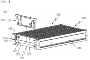
FIG. 1 is a perspective view showing an assembly type of a battery module and a control module in a battery pack of an embodiment of the present disclosure; -
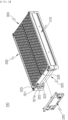
FIG. 2 is a perspective view showing another assembly type of the battery module and the control module in the battery pack of the embodiment of the present disclosure; -
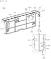
FIG. 3 is one side perspective view of the control module in the battery pack of the embodiment of the present disclosure; -
FIG. 4 is another side perspective view of the control module in the battery pack of the embodiment of the present disclosure; -
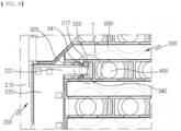
FIG. 5 is a partial plan view showing a state before a thermistor unit comes into contact with a battery cell when the battery module and the control module are assembled in the battery pack of the embodiment of the present disclosure; and -
FIG. 6 is a partial plan view showing a state after the thermistor unit comes into contact with the battery cell when the battery module and the control module are assembled in the battery pack of the embodiment of the present disclosure. - The features, advantages and method for accomplishment of the present invention will be more apparent from referring to the following detailed embodiments described as well as the accompanying drawings. However, the present invention is not limited to the embodiment to be disclosed below and is implemented in different and various forms. The embodiments bring about the complete disclosure of the present invention and are provided to make those skilled in the art fully understand the scope of the present invention. The present invention is just defined by the scope of the appended claims.
- Since the shapes, sizes, proportions, angles, numbers, etc., disclosed in the drawings for describing the embodiments of the present invention are illustrative, the present invention is not limited to the shown details. The same reference numerals throughout the disclosure correspond to the same elements. Also, throughout the description of the present invention, the detailed description of known technologies incorporated herein will be omitted when it may make the subject matter of the present invention unclear. Terms such as "includes", "has", "composed", etc., mentioned in the present disclosure are used, other parts can be added unless a term "only" is used. A component represented in a singular form includes the expression of plural form thereof unless otherwise explicitly mentioned.
- In construing components, error ranges are construed as being included even unless otherwise explicitly mentioned.
- In describing positional relationships, when the positional relationship of two parts is described, for example, "on", "over", "under", "next to", etc., one or more other parts may be positioned between the two parts as long as a term "directly" or "immediately" is not used.
- While terms such as the first and the second, etc., can be used to describe various components, the components are not limited by the terms mentioned above. The terms are used only for distinguishing between one component and other components. Therefore, the first component to be described below may be the second component within the spirit of the present invention.
- The same reference numerals throughout the disclosure correspond to the same elements.
- The size and thickness of each component shown in the drawings may be provided for convenience of description, and the present invention is not necessarily limited to the size and thickness.
- The features of the various embodiments of the present disclosure can be partially or entirely coupled to or combined with each other, and as those skilled in the art can fully understand, the features can be technically and variously connected and driven. Also, the embodiments can be implemented independently of each other or together in an association relationship.
- Hereinafter, preferred embodiments of a battery pack according to the present disclosure will be described in detail with reference to the attached drawings.
- Referring to
FIGS. 1 and2 , abattery pack 100 of the present disclosure may include abattery module 300, acontrol module 200, and athermistor unit 250. - The
battery module 300 may include abattery module frame 310, apartition wall 340, and abus bar 500. - Specifically, the
battery module frame 310 may form an overall appearance of thebattery module 300 and may include acell mounting portion 330 formed therein on which a plurality ofbattery cells 400 can be disposed. Referring toFIGS. 5 and6 , it can be seen that the plurality ofbattery cells 400 is arranged within thebattery module frame 310 in a plurality of columns and rows. Thecell mounting portion 330 is formed within thebattery module frame 310 and protects the plurality ofbattery cells 400 from external impact. - A control
module mounting portion 320 may be formed on one outer side surface of thebattery module frame 310. The controlmodule mounting portion 320 may include asupport block 321, a steppedportion 322, afitting piece 323, and cutportions - The
support block 321 may be arranged to protrude outward from the controlmodule mounting portion 320 and may have afastening hole 321a formed in a central portion thereof. A thread may be processed within thefastening hole 321a such that a bolt can be coupled thereto. In the embodiment of the present disclosure, thesupport block 321 may have a cross shape, but is not limited thereto. - The stepped
portion 322 may be formed inward at both ends of the controlmodule mounting portion 320. Thecontrol module 200 may be inserted into the inside of the steppedportion 322. - The
fitting piece 323 may be disposed below thesupport block 321 in the controlmodule mounting portion 320 and may be formed to protrude outward. In the embodiment of the present disclosure, thefitting piece 323 has a quadrangular shape having one open side, but is not limited thereto. - The
cut portions module mounting portion 320 and may be formed by being cut in an inward direction of thecell mounting portion 330. One ormore cut portions battery cell 400 is measured by inserting thethermistor unit 250 into two points and contacting thethermistor unit 250 with thebattery cell 400, thereby improving the accuracy of an average temperature value of thebattery cell 400. According to design specifications, the temperature of thebattery cell 400 may be measured by forming thecut portions thermistor unit 250 with the battery cell. In this case, the accuracy of the average temperature value of thebattery cell 400 can be further improved. - Next, referring to
FIGS. 5 and6 , thepartition wall 340 is formed on thebattery module frame 310 and may separate the plurality ofbattery cells 400 from each other. Even if aspecific battery cell 400 is degraded and spark or fire occurs locally, thepartition wall 340 blocks the spark or fire or delays the spread of the spark or fire, thereby preventing the spark or fire from spreading toother battery cells 400 or delaying the spread. This can prevent or delay the occurrence of deterioration of theentire battery module 300. Ultimately, when the partition wall is installed in an electric vehicle, the partition wall allows a driver to have evacuation time and fire suppression time. - Referring to
FIGS. 5 and6 , thebus bar 500 may be disposed between thepartition walls 340 over thebattery module frame 310 and may be electrically connected to the plurality ofbattery cells 400. As is known, thebus bar 500 allows the plurality ofbattery cells 400 to be connected in parallel or in series as needed. - Meanwhile, referring to
FIGS. 3 and4 , thecontrol module 200 may be coupled to the controlmodule mounting portion 320 and may control the operation of thebattery cell 400. In the embodiment of the present disclosure, thecontrol module 200 may be a battery management system (BMS) module. - The
control module 200 may include acontrol module frame 210, a main circuit board 230, asub-circuit board 220,circuit extension parts protrusions piece contact portion 211a, and afitting recess 212. - The
control module frame 210 may form an overall appearance of thecontrol module 200 and may be coupled to the controlmodule mounting portion 320. - The main circuit board 230 may be disposed in a central portion of the
control module frame 210. Electronic components capable of controlling thebattery cell 400 may be electrically connected and disposed on the main circuit board 230. In the embodiment of the present disclosure, the main circuit board 230 may be a BMS printed circuit board. - The
sub-circuit board 220 may be electrically connected to the main circuit board 230 and may extend to a top of thecontrol module frame 210. In the embodiment of the present disclosure, unlike a prior art, thesub-circuit board 220 is arranged to extend to the top of thecontrol module frame 210. Here, thesub-circuit board 220 may be a flexible printed circuit board (FPCB). - As such, a technical reason why the
sub-circuit board 220 is disposed up to the top of thecontrol module frame 210 is to extend the electrical circuit connection to theprotrusions - The
protrusions cut portions control module frame 210 toward thecut portions - Also, the
sub-circuit board 220 may be formed with thecircuit extension parts protrusions - Here, the
thermistor unit 250 may be disposed at the ends of theprotrusions circuit extension parts - That is, in the embodiment of the present disclosure, in order to achieve the purpose of improving assemblability and of shortening the manufacturing process by integrating the
thermistor unit 250 into thecontrol module 200, thesub-circuit board 220 is disposed up to the top of thecontrol module frame 210, and thecircuit extension parts sub-circuit board 220 and are disposed up to theprotrusions - Accordingly, an electrical signal is transmitted to the
thermistor unit 250 integrally coupled to thecontrol module 200. When thecontrol module 200 is just assembled to thebattery module 300, thethermistor unit 250 comes into contact with thebattery cell 400 and thus the temperature of thebattery cell 400 can be measured. Accordingly, there is no requirement for a separate attachment process of welding thethermistor unit 250 to thebattery cell 400. - Next, the
piece contact portion 211a may be formed on the upper portion of thecontrol module frame 210. Thesupport block 321 may come into contact with thepiece contact portion 211a. Thepiece contact portion 211a may support an upper position of thecontrol module frame 210. A throughhole 211 that can be bolted to thefastening hole 321a may be formed in the central portion of thepiece contact portion 211a. - The
fitting recess 212 may be formed in a lower portion of thecontrol module frame 210. A fitting block may be inserted into thefitting recess 212. Thefitting recess 212 may support a lower position of thecontrol module frame 210. - Meanwhile, referring to
FIG. 4 , thethermistor unit 250 may be connected to thecontrol module 200, may come into contact with thebattery cell 400, and may measure the temperature of thebattery cell 400. - The
thermistor unit 250 may include athermistor chip 251 and aheat conduction pad 253. - The
thermistor chip 251 may be disposed on end surfaces of theprotrusions - The
heat conduction pad 253 may be disposed on the end surfaces of theprotrusions thermistor chip 251. That is, thethermistor chip 251 does not come into direct contact with thebattery cell 400, and the thermalconductive pad 253 may bring into contact with thebattery cell 400 and the heat of thebattery cell 400 may be conducted through the heat conduction pad and may be transmitted to thethermistor chip 251. Theheat conduction pad 253 may be made of an elastic material, and accordingly, when theheat conduction pad 253 is deformed in shape by contact with thebattery cell 400, theheat conduction pad 253 can maintain the contact state and eliminate gaps in thebattery cell 400. Accordingly, the temperature of thebattery cell 400 can be accurately transmitted to thethermistor chip 251. - Here, referring to
FIGS. 5 and6 ,insertion portions 341 are disposed in both inner sides of thecut portion 325. Theinsertion portions 341 protrude from both inner sides of thecut portion 325 in a direction facing each other. Although not shown in the drawings, a groove is formed in theinsertion portion 341. - Also,
insertion protrusions 217 are disposed on both sides of theprotrusion 215. As theinsertion protrusion 217 is inserted into theinsertion portion 341, the position of theprotrusion 215 is fixed within thecut portion 325. - Due to such a configuration of the
insertion portion 341 and theinsertion protrusion 217, theheat conduction pad 253 can be stably maintained in contact with the surface of thebattery cell 400. - Meanwhile, referring to
FIGS. 5 and6 ,FIG. 5 is a partial plan view showing a state before thethermistor unit 250 comes into contact with thebattery cell 400 when thebattery module 300 and thecontrol module 200 are assembled in thebattery pack 100 of the embodiment of the present disclosure.FIG. 6 is a partial plan view showing a state after thethermistor unit 250 comes into contact with thebattery cell 400 when thebattery module 300 and thecontrol module 200 are assembled in thebattery pack 100 of the embodiment of the present disclosure. - First, referring to
FIG. 5 , thepartition wall 340 and thebus bar 500 are disposed on thebattery module frame 310, and thecut portion 325 is formed in a portion leading from a portion of thepartition wall 340 to the controlmodule mounting portion 320. A pair ofinsertion portions 341 is formed on both inner sides of thecut portion 325. - Also, the
circuit extension part 221 of the flexible printed circuit board extends to theprotrusion 215 on the upper portion of thecontrol module frame 210, and theheat conduction pad 253 is disposed on the end surface of theprotrusion 215. As described above, thethermistor chip 251 is built into theheat conduction pad 253. A pair ofinsertion protrusions 217 is formed on both sides of theprotrusion 215. - Next, referring to
FIG. 6 , thecontrol module 200 is assembled to the controlmodule mounting portion 320 of thebattery module frame 310. That is, thecontrol module 200 is pushed into the steppedportion 322 of the controlmodule mounting portion 320, and then the throughhole 211 and thefastening hole 321a are bolted. - Here, referring to an area marked with Y, the
protrusion 215 is further inserted into thecut portion 325, and theheat conduction pad 253 comes into contact with the surface of thebattery cell 400. At the same time, as theinsertion protrusion 217 is inserted into theinsertion portion 341, the position of theprotrusion 215 is fixed within thecut portion 325. - As such, only by a simple process of assembling the
control module 200 to thebattery module 300, thethermistor unit 250 automatically comes into contact with thebattery cell 400, thereby measuring the temperature of thebattery cell 400. - According to the embodiment of the present disclosure, the
control module 200 and thethermistor unit 250 are integrated with each other. Therefore, when thecontrol module 200 and thebattery module 300 are coupled, thethermistor unit 250 automatically comes into contact with thebattery cell 400. Accordingly, ultimately, there are technical effects of improving assemblability of thebattery pack 100 and of shortening the manufacturing process. Also, it is possible to increase the operational stability of thethermistor unit 250 compared to a conventional soldering method and to measure the temperature of thebattery cell 400 more accurately. - The above descriptions merely show a specific embodiment of the battery pack.
- Therefore, it is clear that those skilled in the art can easily understand that the present invention can be substituted and modified in various forms without departing from the spirit of the present disclosure disclosed in the following claims.
- The present disclosure relates to a battery pack and has industrial applicability
Claims (6)
- A battery pack comprising:a battery module configured to include a battery module frame including a cell mounting portion formed therein on which a plurality of battery cells is disposed and a control module mounting portion formed on one outer side surface thereof;a control module configured to be coupled to the control module mounting portion and control operations of the battery cell; anda thermistor unit configured to be connected to the control module, to come into contact with the battery cell, and to measure a temperature of the battery cell.
- The battery pack of claim 1, wherein the control module comprises:a control module frame configured to be coupled to the control module mounting portion;a main circuit board configured to be disposed on the control module frame; anda sub-circuit board configured to be disposed on the control module frame and to be electrically connected to the main circuit board.
- The battery pack of claim 2,wherein one or more cut portions are formed by being cut in an inward direction of the cell mounting portion,wherein one or more protrusions are formed at positions corresponding to the cut portions in the control module frame in such a way as to protrude toward the cut portions,wherein the sub-circuit board is formed with a circuit extension part which extends to the protrusion,wherein the thermistor unit is electrically connected to the circuit extension part is disposed at an end of the protrusion,and wherein, when the protrusion is inserted into the cut portion, the thermistor unit comes into contact with the battery cell.
- The battery pack of claim 3, wherein the thermistor unit comprises:a thermistor chip configured to be disposed on an end surface of the protrusion; anda heat conduction pad configured to be disposed on the end surface of the protrusion and to surround the thermistor chip.
- The battery pack of claim 3, comprising:an insertion portion configured to be disposed in both inner sides of the cut portion and to protrude in a direction facing each other; andan insertion protrusion configured to be disposed on both sides of the protrusion and to be inserted into the insertion portion.
- The battery pack of claim 3,wherein the battery module further comprises:a support block configured to be arranged to protrude outward from the control module mounting portion and has a fastening hole formed therein;a stepped portion configured to be formed inward at both ends of the control module mounting portion and to allow the control module frame to be inserted thereinto; anda fitting piece configured to be formed to protrude outward from the control module mounting portion,and wherein the control module comprises:a piece contact portion configured to be formed in the control module frame, to allow the support block to contact, to support the control module frame, and to have a through hole that is bolted to the fastening hole; anda fitting recess configured to be formed in the control module frame, to allow the fitting piece to be inserted thereinto, and to support the control module frame.
Applications Claiming Priority (2)
| Application Number | Priority Date | Filing Date | Title |
|---|---|---|---|
| KR1020210096633A KR20230015187A (en) | 2021-07-22 | 2021-07-22 | Battery pack |
| PCT/KR2022/010190 WO2023003259A1 (en) | 2021-07-22 | 2022-07-13 | Battery pack |
Publications (1)
| Publication Number | Publication Date |
|---|---|
| EP4366027A1 true EP4366027A1 (en) | 2024-05-08 |
Family
ID=84979403
Family Applications (1)
| Application Number | Title | Priority Date | Filing Date |
|---|---|---|---|
| EP22846129.9A Pending EP4366027A1 (en) | 2021-07-22 | 2022-07-13 | Battery pack |
Country Status (4)
| Country | Link |
|---|---|
| EP (1) | EP4366027A1 (en) |
| KR (1) | KR20230015187A (en) |
| CN (1) | CN117751479A (en) |
| WO (1) | WO2023003259A1 (en) |
Family Cites Families (5)
| Publication number | Priority date | Publication date | Assignee | Title |
|---|---|---|---|---|
| KR101210088B1 (en) * | 2010-07-29 | 2012-12-07 | 삼성에스디아이 주식회사 | Protection circuit module including thermistor and battery pack with same |
| KR101764837B1 (en) * | 2014-11-05 | 2017-08-03 | 주식회사 엘지화학 | Battery module and battery pack including the same |
| KR101726775B1 (en) * | 2014-11-17 | 2017-04-13 | 주식회사 엘지화학 | Temperature Sensing Circuit Having Compact Circuit Structure |
| KR102046000B1 (en) * | 2015-08-24 | 2019-11-18 | 주식회사 엘지화학 | Battery Pack with Improved Temperature Sensing Ability |
| KR102256600B1 (en) * | 2017-02-16 | 2021-05-26 | 주식회사 엘지에너지솔루션 | Battery module, battery pack comprising the battery module and vehicle comprising the battery pack |
-
2021
- 2021-07-22 KR KR1020210096633A patent/KR20230015187A/en unknown
-
2022
- 2022-07-13 CN CN202280050180.7A patent/CN117751479A/en active Pending
- 2022-07-13 EP EP22846129.9A patent/EP4366027A1/en active Pending
- 2022-07-13 WO PCT/KR2022/010190 patent/WO2023003259A1/en active Application Filing
Also Published As
| Publication number | Publication date |
|---|---|
| WO2023003259A1 (en) | 2023-01-26 |
| CN117751479A (en) | 2024-03-22 |
| KR20230015187A (en) | 2023-01-31 |
Similar Documents
| Publication | Publication Date | Title |
|---|---|---|
| US7609028B2 (en) | Sensing board assembly for secondary battery module | |
| EP3651237B1 (en) | Battery pack with improved assembly structure | |
| JP5198274B2 (en) | Novel bus bar for electrical connection and battery module including the same | |
| CN107112483B (en) | Mounting structure for mounting temperature detection member to bus bar, wiring module, and method for manufacturing wiring module | |
| US7537720B2 (en) | PCM mold and battery having the same | |
| JP5450634B2 (en) | Secondary battery pack having a novel structure | |
| JP2010097722A (en) | Battery module | |
| US20130034752A1 (en) | Secondary battery pack with improved safety | |
| US9269946B2 (en) | Battery pack having protection circuit module | |
| US10355255B2 (en) | Battery module and battery pack comprising same | |
| WO2023185289A1 (en) | Cell-to-pack battery system | |
| KR20160085621A (en) | Battery module | |
| WO2018199222A1 (en) | Current detecting device, management device, and battery for starting engine | |
| US10770700B2 (en) | Battery pack | |
| JP2013098032A (en) | Connection structure of voltage detection terminal | |
| KR20170101604A (en) | Battery pack | |
| KR101802926B1 (en) | Battery having Sensing Assembly Structure for Processing Signal of Cell | |
| KR100971368B1 (en) | Battery Pack of Non-welding Electrical Connection Type | |
| US20220285755A1 (en) | Top Cooling Type Battery Pack | |
| US20140003016A1 (en) | Battery monitoring system | |
| KR101636380B1 (en) | Voltage Sensing Assembly and Battery Module Including the Same | |
| EP4366027A1 (en) | Battery pack | |
| KR101985836B1 (en) | Battery pack | |
| JP2013098031A (en) | Mounting structure of thermistor | |
| RU2794728C1 (en) | Battery module monitoring device and battery module for electric vehicle |
Legal Events
| Date | Code | Title | Description |
|---|---|---|---|
| STAA | Information on the status of an ep patent application or granted ep patent |
Free format text: STATUS: THE INTERNATIONAL PUBLICATION HAS BEEN MADE |
|
| PUAI | Public reference made under article 153(3) epc to a published international application that has entered the european phase |
Free format text: ORIGINAL CODE: 0009012 |
|
| STAA | Information on the status of an ep patent application or granted ep patent |
Free format text: STATUS: REQUEST FOR EXAMINATION WAS MADE |
|
| 17P | Request for examination filed |
Effective date: 20240202 |
|
| AK | Designated contracting states |
Kind code of ref document: A1 Designated state(s): AL AT BE BG CH CY CZ DE DK EE ES FI FR GB GR HR HU IE IS IT LI LT LU LV MC MK MT NL NO PL PT RO RS SE SI SK SM TR |