EP4366013A1 - Apparatus for manufacturing pouch type rechargeable-battery - Google Patents
Apparatus for manufacturing pouch type rechargeable-battery Download PDFInfo
- Publication number
- EP4366013A1 EP4366013A1 EP23207569.7A EP23207569A EP4366013A1 EP 4366013 A1 EP4366013 A1 EP 4366013A1 EP 23207569 A EP23207569 A EP 23207569A EP 4366013 A1 EP4366013 A1 EP 4366013A1
- Authority
- EP
- European Patent Office
- Prior art keywords
- protrusion
- pouch
- folding
- rechargeable battery
- mold
- Prior art date
- Legal status (The legal status is an assumption and is not a legal conclusion. Google has not performed a legal analysis and makes no representation as to the accuracy of the status listed.)
- Pending
Links
Images




Classifications
-
- H—ELECTRICITY
- H01—ELECTRIC ELEMENTS
- H01M—PROCESSES OR MEANS, e.g. BATTERIES, FOR THE DIRECT CONVERSION OF CHEMICAL ENERGY INTO ELECTRICAL ENERGY
- H01M10/00—Secondary cells; Manufacture thereof
- H01M10/04—Construction or manufacture in general
- H01M10/0404—Machines for assembling batteries
-
- H—ELECTRICITY
- H01—ELECTRIC ELEMENTS
- H01M—PROCESSES OR MEANS, e.g. BATTERIES, FOR THE DIRECT CONVERSION OF CHEMICAL ENERGY INTO ELECTRICAL ENERGY
- H01M10/00—Secondary cells; Manufacture thereof
- H01M10/04—Construction or manufacture in general
-
- B—PERFORMING OPERATIONS; TRANSPORTING
- B29—WORKING OF PLASTICS; WORKING OF SUBSTANCES IN A PLASTIC STATE IN GENERAL
- B29C—SHAPING OR JOINING OF PLASTICS; SHAPING OF MATERIAL IN A PLASTIC STATE, NOT OTHERWISE PROVIDED FOR; AFTER-TREATMENT OF THE SHAPED PRODUCTS, e.g. REPAIRING
- B29C66/00—General aspects of processes or apparatus for joining preformed parts
- B29C66/40—General aspects of joining substantially flat articles, e.g. plates, sheets or web-like materials; Making flat seams in tubular or hollow articles; Joining single elements to substantially flat surfaces
- B29C66/41—Joining substantially flat articles ; Making flat seams in tubular or hollow articles
- B29C66/43—Joining a relatively small portion of the surface of said articles
- B29C66/433—Casing-in, i.e. enclosing an element between two sheets by an outlined seam
- B29C66/4332—Casing-in, i.e. enclosing an element between two sheets by an outlined seam by folding a sheet over
-
- B—PERFORMING OPERATIONS; TRANSPORTING
- B29—WORKING OF PLASTICS; WORKING OF SUBSTANCES IN A PLASTIC STATE IN GENERAL
- B29C—SHAPING OR JOINING OF PLASTICS; SHAPING OF MATERIAL IN A PLASTIC STATE, NOT OTHERWISE PROVIDED FOR; AFTER-TREATMENT OF THE SHAPED PRODUCTS, e.g. REPAIRING
- B29C53/00—Shaping by bending, folding, twisting, straightening or flattening; Apparatus therefor
- B29C53/02—Bending or folding
- B29C53/04—Bending or folding of plates or sheets
-
- B—PERFORMING OPERATIONS; TRANSPORTING
- B29—WORKING OF PLASTICS; WORKING OF SUBSTANCES IN A PLASTIC STATE IN GENERAL
- B29C—SHAPING OR JOINING OF PLASTICS; SHAPING OF MATERIAL IN A PLASTIC STATE, NOT OTHERWISE PROVIDED FOR; AFTER-TREATMENT OF THE SHAPED PRODUCTS, e.g. REPAIRING
- B29C53/00—Shaping by bending, folding, twisting, straightening or flattening; Apparatus therefor
- B29C53/02—Bending or folding
- B29C53/04—Bending or folding of plates or sheets
- B29C53/043—Bending or folding of plates or sheets using rolls or endless belts
-
- B—PERFORMING OPERATIONS; TRANSPORTING
- B29—WORKING OF PLASTICS; WORKING OF SUBSTANCES IN A PLASTIC STATE IN GENERAL
- B29C—SHAPING OR JOINING OF PLASTICS; SHAPING OF MATERIAL IN A PLASTIC STATE, NOT OTHERWISE PROVIDED FOR; AFTER-TREATMENT OF THE SHAPED PRODUCTS, e.g. REPAIRING
- B29C53/00—Shaping by bending, folding, twisting, straightening or flattening; Apparatus therefor
- B29C53/02—Bending or folding
- B29C53/04—Bending or folding of plates or sheets
- B29C53/06—Forming folding lines by pressing or scoring
-
- B—PERFORMING OPERATIONS; TRANSPORTING
- B29—WORKING OF PLASTICS; WORKING OF SUBSTANCES IN A PLASTIC STATE IN GENERAL
- B29C—SHAPING OR JOINING OF PLASTICS; SHAPING OF MATERIAL IN A PLASTIC STATE, NOT OTHERWISE PROVIDED FOR; AFTER-TREATMENT OF THE SHAPED PRODUCTS, e.g. REPAIRING
- B29C65/00—Joining or sealing of preformed parts, e.g. welding of plastics materials; Apparatus therefor
- B29C65/02—Joining or sealing of preformed parts, e.g. welding of plastics materials; Apparatus therefor by heating, with or without pressure
-
- B—PERFORMING OPERATIONS; TRANSPORTING
- B29—WORKING OF PLASTICS; WORKING OF SUBSTANCES IN A PLASTIC STATE IN GENERAL
- B29C—SHAPING OR JOINING OF PLASTICS; SHAPING OF MATERIAL IN A PLASTIC STATE, NOT OTHERWISE PROVIDED FOR; AFTER-TREATMENT OF THE SHAPED PRODUCTS, e.g. REPAIRING
- B29C66/00—General aspects of processes or apparatus for joining preformed parts
- B29C66/01—General aspects dealing with the joint area or with the area to be joined
- B29C66/03—After-treatments in the joint area
- B29C66/032—Mechanical after-treatments
- B29C66/0324—Reforming or reshaping the joint, e.g. folding over
-
- B—PERFORMING OPERATIONS; TRANSPORTING
- B29—WORKING OF PLASTICS; WORKING OF SUBSTANCES IN A PLASTIC STATE IN GENERAL
- B29C—SHAPING OR JOINING OF PLASTICS; SHAPING OF MATERIAL IN A PLASTIC STATE, NOT OTHERWISE PROVIDED FOR; AFTER-TREATMENT OF THE SHAPED PRODUCTS, e.g. REPAIRING
- B29C67/00—Shaping techniques not covered by groups B29C39/00 - B29C65/00, B29C70/00 or B29C73/00
- B29C67/0044—Shaping techniques not covered by groups B29C39/00 - B29C65/00, B29C70/00 or B29C73/00 for shaping edges or extremities
-
- H—ELECTRICITY
- H01—ELECTRIC ELEMENTS
- H01M—PROCESSES OR MEANS, e.g. BATTERIES, FOR THE DIRECT CONVERSION OF CHEMICAL ENERGY INTO ELECTRICAL ENERGY
- H01M50/00—Constructional details or processes of manufacture of the non-active parts of electrochemical cells other than fuel cells, e.g. hybrid cells
- H01M50/10—Primary casings; Jackets or wrappings
- H01M50/102—Primary casings; Jackets or wrappings characterised by their shape or physical structure
- H01M50/105—Pouches or flexible bags
-
- B—PERFORMING OPERATIONS; TRANSPORTING
- B29—WORKING OF PLASTICS; WORKING OF SUBSTANCES IN A PLASTIC STATE IN GENERAL
- B29L—INDEXING SCHEME ASSOCIATED WITH SUBCLASS B29C, RELATING TO PARTICULAR ARTICLES
- B29L2031/00—Other particular articles
- B29L2031/712—Containers; Packaging elements or accessories, Packages
- B29L2031/7146—Battery-cases
-
- H—ELECTRICITY
- H01—ELECTRIC ELEMENTS
- H01M—PROCESSES OR MEANS, e.g. BATTERIES, FOR THE DIRECT CONVERSION OF CHEMICAL ENERGY INTO ELECTRICAL ENERGY
- H01M10/00—Secondary cells; Manufacture thereof
- H01M10/04—Construction or manufacture in general
- H01M10/0413—Large-sized flat cells or batteries for motive or stationary systems with plate-like electrodes
-
- Y—GENERAL TAGGING OF NEW TECHNOLOGICAL DEVELOPMENTS; GENERAL TAGGING OF CROSS-SECTIONAL TECHNOLOGIES SPANNING OVER SEVERAL SECTIONS OF THE IPC; TECHNICAL SUBJECTS COVERED BY FORMER USPC CROSS-REFERENCE ART COLLECTIONS [XRACs] AND DIGESTS
- Y02—TECHNOLOGIES OR APPLICATIONS FOR MITIGATION OR ADAPTATION AGAINST CLIMATE CHANGE
- Y02E—REDUCTION OF GREENHOUSE GAS [GHG] EMISSIONS, RELATED TO ENERGY GENERATION, TRANSMISSION OR DISTRIBUTION
- Y02E60/00—Enabling technologies; Technologies with a potential or indirect contribution to GHG emissions mitigation
- Y02E60/10—Energy storage using batteries
-
- Y—GENERAL TAGGING OF NEW TECHNOLOGICAL DEVELOPMENTS; GENERAL TAGGING OF CROSS-SECTIONAL TECHNOLOGIES SPANNING OVER SEVERAL SECTIONS OF THE IPC; TECHNICAL SUBJECTS COVERED BY FORMER USPC CROSS-REFERENCE ART COLLECTIONS [XRACs] AND DIGESTS
- Y02—TECHNOLOGIES OR APPLICATIONS FOR MITIGATION OR ADAPTATION AGAINST CLIMATE CHANGE
- Y02P—CLIMATE CHANGE MITIGATION TECHNOLOGIES IN THE PRODUCTION OR PROCESSING OF GOODS
- Y02P70/00—Climate change mitigation technologies in the production process for final industrial or consumer products
- Y02P70/50—Manufacturing or production processes characterised by the final manufactured product
Definitions
- the present disclosure relates to an apparatus for manufacturing a pouch-type rechargeable-battery.
- Pouch-type secondary batteries may be divided into unidirectional pouch-type secondary batteries and bidirectional pouch-type secondary batteries depending on the direction of the electrode leads thereof, and may be divided into three-side sealing pouch-type secondary batteries and four-side sealing pouch-type secondary batteries, depending on the number of sealing surfaces.
- both ends of the non-sealed side protrude, and this is generally known by various names such as a shark-fin, a bat ear, or the like.
- a plurality of pouch-type secondary batteries may be accommodated in a case and the like and manufactured as rechargeable battery modules and rechargeable battery packs.
- An aspect of the present disclosure is to provide an apparatus for manufacturing a pouch-type rechargeable battery, in which protrusions may be removed or heights of protrusions may be reduced.
- an apparatus for manufacturing a pouch-type rechargeable battery includes a preforming portion forming a folding groove in a portion of a protrusion of the pouch-type rechargeable battery, a folding portion disposed on a rear end of the preforming portion and folding the protrusion along the folding groove, a rolling portion disposed on a rear end of the folding portion and pressing the folded protrusion, and a pressing portion disposed on a rear end of the rolling portion and fixing the folded protrusion.
- the preforming portion may include a seating table on which the pouch-type rechargeable battery is seated, a first mold on which a portion of the protrusion is seated and which is provided with a groove, and a second mold coupled to the first mold and provided with a protrusion inserted into the groove.
- At least one of the second mold and the first mold may be lifted and lowered for coupling.
- the folding portion may include a fixture fixing the pouch-type rechargeable battery, and a folding mold disposed adjacent to the fixture and raised and lowered.
- the folding mold may be provided with an inclined surface contacting the protrusion.
- the folding mold may be provided with a first surface disposed on a bottom end of the inclined surface and disposed perpendicularly to a bottom surface of the folding mold.
- the rolling portion may include a roller pressing the folded protrusion, and a moving frame on which the roller is rotatably installed and which moves the roller in a longitudinal direction of the pouch-type rechargeable battery.
- the roller may be disposed to be inclined with respect to a thickness direction of the pouch-type rechargeable battery.
- the pressing portion may include a fixing bar fixing a terrace portion of the pouch-type rechargeable battery, and a pressing member spaced apart from the fixing bar and applying heat and pressure to the folded protrusion.
- the pressing member may be in contact with the folded protrusion and may be moved to be spaced apart from the protrusion.
- the roller may have an inclination angle of 15° to 45°.
- protrusions formed in the pouch-type rechargeable battery is removed or the height of the protrusions is reduced.
- protrusions are formed on both ends of a non-sealed side. And the protrusions are generally called by various names such as shark-fins, bat ears, or the like.
- An apparatus for manufacturing a pouch-type rechargeable battery relates to an apparatus for removing protrusions after the three-side sealing of the pouch film is completed.
- an apparatus for manufacturing a pouch-type rechargeable battery includes a preforming portion 100.
- the preforming portion 100 includes a seating table 110 on which a pouch-type rechargeable battery 10 is seated, a first mold 120 disposed adjacent to the seating table 110 and on which the end of the protrusion 20 of the pouch-type rechargeable battery 10 is seated, and a second mold 130 combined with first mold 120.
- the first mold 120 may be provided with a groove 122 for forming a folding groove in the protrusion 20
- the second mold 130 may be provided with a protrusion 132 inserted into the groove 122 of the first mold 120.
- the pouch-type rechargeable battery 10 seated on the seating table 110 is aligned such that a portion of the protrusion 20 is seated on the first mold 120.
- the alignment of the pouch-type rechargeable battery 10 may be performed by adjusting the position of the seating table 110, and the position of the pouch-type rechargeable battery 10 may also be aligned using a separate alignment unit.
- the second mold 130 descends and is coupled to the first mold 120 and then rises.
- the protrusion 132 of the second mold 130 is inserted into the groove 122 of the first mold 120 together with the protrusion 20. Accordingly, a folding groove 22 is formed in the protrusion 20 of the pouch-type rechargeable battery 10.
- the apparatus for manufacturing a pouch-type rechargeable battery may further include a folding portion 200.
- the folding portion 200 includes a fixture 210 that fixes the pouch-type rechargeable battery 10, and a folding mold 220 that is disposed adjacent to the fixture 210 and is raised and lowered.
- the fixture 210 serves to fix the pouch-type rechargeable battery 10 and maintain a certain position thereof when the protrusion 20 is folded by the folding mold 220.
- the fixture 210 may fix the sealing portion adjacent to the protrusion 20.
- the folding mold 220 has an inclined surface 222, and when the folding mold 220 rises, the protrusion 20 of the pouch-type rechargeable battery 10 contacts the inclined surface 222 and is folded.
- the inclined surface 222 reduces friction applied to the protrusion 20 such that the folding operation of the protrusion 20 may be performed more smoothly.
- the folding groove 22 is formed in the protrusion 20, the part where the protrusion 20 is folded may be constant.
- the protrusion 20 of the pouch-type rechargeable battery 10 is finally folded by a first surface 224 provided on a bottom end of the inclined surface 222.
- the first surface 224 may be a surface perpendicular to the bottom surface of the folding mold 220.
- the apparatus for manufacturing a pouch-type rechargeable battery may further include a rolling portion 300.
- the rolling portion 300 may include a roller 310 that presses the folded protrusion 20, and a moving frame 320 in which the roller 310 is rotatably installed and which moves the roller 310 in the longitudinal direction of the pouch-type rechargeable battery 10, for example, in the X-axis direction of FIG. 5 .
- the roller 310 may be disposed to be inclined with respect to the thickness direction of the pouch-type rechargeable battery 10, for example, the Z-axis direction in FIG. 5 .
- the roller 310 may be disposed to have an inclination angle of approximately 15° to 45° with respect to the Z axis.
- the protrusion 20 is folded by the rolling of the roller 310, thereby reducing damage to the pouch film.
- the roller 310 is disposed perpendicular to the pouch-type rechargeable battery 10 and the protrusion 20 is pressed by rolling by the roller 310, as the entire protrusion 20 is crushed, the area in which the protrusion 20 is formed may be torn or the height of the protrusion 20 may increase.
- the roller 310 by disposing the roller 310 to be inclined, the protrusion 20 may be pressed by the rolling of the roller 310, and thus, the roller may move constantly in the folding direction of the protrusion 20.
- the apparatus for manufacturing a pouch-type rechargeable battery may further include a pressing portion 400.
- the pressing portion 400 may include a fixing bar 410 for fixing a terrace portion 30 of the pouch-type rechargeable battery 10, and a pressing member 420 disposed to be spaced apart from the fixing bar 410 and pressing the protrusion 20 of the pouch-type rechargeable battery 10 by heat and pressure to maintain the protrusion 20 in a folded state.
- the pressing member 420 may move toward the pouch-type rechargeable battery 10, press the protrusion 20 by heat and pressure, and then move to be away from the pouch-type rechargeable battery 10.
- the preforming portion 100, the folding portion 200, the rolling portion 300, and the pressing portion 400 are sequentially disposed to be adjacent to each other, and the pouch-type rechargeable battery 10 is seated on the seating table 110 and may pass through the preforming portion 100, the folding portion 200, the rolling portion 300, and the pressing portion 400 as the seating table 110 moves.
- the folded portion of the protrusion 20 may be prevented from unfolding.
- the protrusion 20 since the protrusion 20 is folded by the rolling of the roller 310 of the rolling portion 300, the protrusion 20 may be removed or the height of the protrusion 20 may be reduced, and damage to the pouch film may be prevented.
- embodiments of the present disclosure have the effect of removing protrusions formed in the pouch-type rechargeable battery or reducing the height of the protrusions.
Landscapes
- Engineering & Computer Science (AREA)
- Mechanical Engineering (AREA)
- Chemical & Material Sciences (AREA)
- Chemical Kinetics & Catalysis (AREA)
- Electrochemistry (AREA)
- General Chemical & Material Sciences (AREA)
- Manufacturing & Machinery (AREA)
- Sealing Battery Cases Or Jackets (AREA)
- Secondary Cells (AREA)
Abstract
Description
- The present disclosure relates to an apparatus for manufacturing a pouch-type rechargeable-battery.
- Pouch-type secondary batteries may be divided into unidirectional pouch-type secondary batteries and bidirectional pouch-type secondary batteries depending on the direction of the electrode leads thereof, and may be divided into three-side sealing pouch-type secondary batteries and four-side sealing pouch-type secondary batteries, depending on the number of sealing surfaces.
- On the other hand, in the case of a three-side sealing pouch type rechargeable battery, both ends of the non-sealed side protrude, and this is generally known by various names such as a shark-fin, a bat ear, or the like.
- On the other hand, a plurality of pouch-type secondary batteries may be accommodated in a case and the like and manufactured as rechargeable battery modules and rechargeable battery packs.
- However, there is a problem in which the volume density is lowered when manufacturing a rechargeable battery module or rechargeable battery pack due to the above-described protrusions, and furthermore, there is a problem in which cooling efficiency may be reduced.
- An aspect of the present disclosure is to provide an apparatus for manufacturing a pouch-type rechargeable battery, in which protrusions may be removed or heights of protrusions may be reduced.
- In some embodiments of the present disclosure, an apparatus for manufacturing a pouch-type rechargeable battery includes a preforming portion forming a folding groove in a portion of a protrusion of the pouch-type rechargeable battery, a folding portion disposed on a rear end of the preforming portion and folding the protrusion along the folding groove, a rolling portion disposed on a rear end of the folding portion and pressing the folded protrusion, and a pressing portion disposed on a rear end of the rolling portion and fixing the folded protrusion.
- The preforming portion may include a seating table on which the pouch-type rechargeable battery is seated, a first mold on which a portion of the protrusion is seated and which is provided with a groove, and a second mold coupled to the first mold and provided with a protrusion inserted into the groove.
- At least one of the second mold and the first mold may be lifted and lowered for coupling.
- The folding portion may include a fixture fixing the pouch-type rechargeable battery, and a folding mold disposed adjacent to the fixture and raised and lowered.
- The folding mold may be provided with an inclined surface contacting the protrusion.
- The folding mold may be provided with a first surface disposed on a bottom end of the inclined surface and disposed perpendicularly to a bottom surface of the folding mold.
- The rolling portion may include a roller pressing the folded protrusion, and a moving frame on which the roller is rotatably installed and which moves the roller in a longitudinal direction of the pouch-type rechargeable battery.
- The roller may be disposed to be inclined with respect to a thickness direction of the pouch-type rechargeable battery.
- The pressing portion may include a fixing bar fixing a terrace portion of the pouch-type rechargeable battery, and a pressing member spaced apart from the fixing bar and applying heat and pressure to the folded protrusion.
- The pressing member may be in contact with the folded protrusion and may be moved to be spaced apart from the protrusion.
- The roller may have an inclination angle of 15° to 45°.
- In some embodiment of the present disclosures, protrusions formed in the pouch-type rechargeable battery is removed or the height of the protrusions is reduced.
- Certain aspects, features, and advantages of the present disclosure are illustrated by the following detailed description with reference to the accompanying drawings.
-
FIGS. 1 and2 are explanatory diagrams illustrating a preforming portion of an apparatus for manufacturing a pouch-type rechargeable battery. -
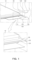
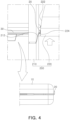
FIGS. 3 and4 are explanatory diagrams illustrating a folding portion of an apparatus for manufacturing a pouch-type rechargeable battery. -
FIGS. 5 and6 are explanatory diagrams illustrating a rolling portion of an apparatus for manufacturing a pouch-type rechargeable battery. -
FIG. 7 is an explanatory diagram illustrating a pressing portion of an apparatus for manufacturing a pouch-type rechargeable battery. - Hereinafter, example embodiments of the present disclosure will be described with reference to the attached drawings. The shapes and sizes of elements in drawings may be exaggerated for clearer explanation.
- In addition, in this specification, singular expressions include plural expressions, unless the context clearly indicates otherwise. Throughout the specification, the same reference numerals refer to the same or corresponding components.
- In addition, in this specification, expressions such as a top side, top portion, bottom side, bottom portion, side, side surface, front, rear, and the like are expressed based on the direction illustrated in the drawing, and it is noted in advance that if the direction of the object changes, it may be expressed differently.
- Hereinafter, respective components included in an apparatus for manufacturing a pouch-type rechargeable battery will be sequentially described with reference to the drawings.
- On the other hand, in the case of a three-side sealing pouch-type rechargeable battery (see 10 in
FIG. 5 ), protrusions are formed on both ends of a non-sealed side. And the protrusions are generally called by various names such as shark-fins, bat ears, or the like. An apparatus for manufacturing a pouch-type rechargeable battery relates to an apparatus for removing protrusions after the three-side sealing of the pouch film is completed. - First, as illustrated in
FIG. 1 , an apparatus for manufacturing a pouch-type rechargeable battery includes a preformingportion 100. The preformingportion 100 includes a seating table 110 on which a pouch-typerechargeable battery 10 is seated, afirst mold 120 disposed adjacent to the seating table 110 and on which the end of theprotrusion 20 of the pouch-typerechargeable battery 10 is seated, and asecond mold 130 combined withfirst mold 120. - On the other hand, the
first mold 120 may be provided with agroove 122 for forming a folding groove in theprotrusion 20, and thesecond mold 130 may be provided with aprotrusion 132 inserted into thegroove 122 of thefirst mold 120. - Then, the pouch-type
rechargeable battery 10 seated on the seating table 110 is aligned such that a portion of theprotrusion 20 is seated on thefirst mold 120. In this case, the alignment of the pouch-typerechargeable battery 10 may be performed by adjusting the position of the seating table 110, and the position of the pouch-typerechargeable battery 10 may also be aligned using a separate alignment unit. - In addition, as illustrated in
FIG. 2 , thesecond mold 130 descends and is coupled to thefirst mold 120 and then rises. On the other hand, when thesecond mold 130 is lowered and coupled to thefirst mold 120, theprotrusion 132 of thesecond mold 130 is inserted into thegroove 122 of thefirst mold 120 together with theprotrusion 20. Accordingly, afolding groove 22 is formed in theprotrusion 20 of the pouch-typerechargeable battery 10. - Next, as illustrated in
FIG. 3 , the apparatus for manufacturing a pouch-type rechargeable battery may further include afolding portion 200. Thefolding portion 200 includes afixture 210 that fixes the pouch-typerechargeable battery 10, and afolding mold 220 that is disposed adjacent to thefixture 210 and is raised and lowered. Thefixture 210 serves to fix the pouch-typerechargeable battery 10 and maintain a certain position thereof when theprotrusion 20 is folded by the foldingmold 220. As an example, thefixture 210 may fix the sealing portion adjacent to theprotrusion 20. On the other hand, thefolding mold 220 has aninclined surface 222, and when the foldingmold 220 rises, theprotrusion 20 of the pouch-typerechargeable battery 10 contacts theinclined surface 222 and is folded. Theinclined surface 222 reduces friction applied to theprotrusion 20 such that the folding operation of theprotrusion 20 may be performed more smoothly. In addition, since thefolding groove 22 is formed in theprotrusion 20, the part where theprotrusion 20 is folded may be constant. - Thereafter, as illustrated in
FIG. 4 , theprotrusion 20 of the pouch-typerechargeable battery 10 is finally folded by afirst surface 224 provided on a bottom end of theinclined surface 222. On the other hand, thefirst surface 224 may be a surface perpendicular to the bottom surface of the foldingmold 220. - On the other hand, as illustrated in
FIG. 5 , the apparatus for manufacturing a pouch-type rechargeable battery may further include a rollingportion 300. Therolling portion 300 may include aroller 310 that presses the foldedprotrusion 20, and a movingframe 320 in which theroller 310 is rotatably installed and which moves theroller 310 in the longitudinal direction of the pouch-typerechargeable battery 10, for example, in the X-axis direction ofFIG. 5 . - In addition, the
roller 310 may be disposed to be inclined with respect to the thickness direction of the pouch-typerechargeable battery 10, for example, the Z-axis direction inFIG. 5 . As an example, theroller 310 may be disposed to have an inclination angle of approximately 15° to 45° with respect to the Z axis. - In addition, as illustrated in
FIG. 6 , as theroller 310 moves in the X-axis direction, theprotrusion 20 is folded by the rolling of theroller 310, thereby reducing damage to the pouch film. For example, in the case in which theroller 310 is disposed perpendicular to the pouch-typerechargeable battery 10 and theprotrusion 20 is pressed by rolling by theroller 310, as theentire protrusion 20 is crushed, the area in which theprotrusion 20 is formed may be torn or the height of theprotrusion 20 may increase. However, according to the present disclosure, by disposing theroller 310 to be inclined, theprotrusion 20 may be pressed by the rolling of theroller 310, and thus, the roller may move constantly in the folding direction of theprotrusion 20. - On the other hand, as illustrated in
FIG. 7 , the apparatus for manufacturing a pouch-type rechargeable battery may further include apressing portion 400. As an example, thepressing portion 400 may include afixing bar 410 for fixing aterrace portion 30 of the pouch-typerechargeable battery 10, and apressing member 420 disposed to be spaced apart from thefixing bar 410 and pressing theprotrusion 20 of the pouch-typerechargeable battery 10 by heat and pressure to maintain theprotrusion 20 in a folded state. - The pressing
member 420 may move toward the pouch-typerechargeable battery 10, press theprotrusion 20 by heat and pressure, and then move to be away from the pouch-typerechargeable battery 10. - The preforming
portion 100, thefolding portion 200, therolling portion 300, and thepressing portion 400 are sequentially disposed to be adjacent to each other, and the pouch-typerechargeable battery 10 is seated on the seating table 110 and may pass through the preformingportion 100, thefolding portion 200, therolling portion 300, and thepressing portion 400 as the seating table 110 moves. - As described above, after forming the
folding groove 22 in the part where theprotrusion 20 is folded through the preformingportion 100, as theprotrusion 20 is folded through thefolding portion 200, the rollingportion 300, and thepressing portion 400, the folded portion of theprotrusion 20 may be prevented from unfolding. - In addition, since the
protrusion 20 is folded by the rolling of theroller 310 of the rollingportion 300, theprotrusion 20 may be removed or the height of theprotrusion 20 may be reduced, and damage to the pouch film may be prevented. - As set forth above, embodiments of the present disclosure have the effect of removing protrusions formed in the pouch-type rechargeable battery or reducing the height of the protrusions.
- Only specific examples of implementations of certain embodiments are described. Variations, improvements and enhancements of the disclosed embodiments and other embodiments may be made based on the disclosure of this patent document.
Claims (11)
- An apparatus for manufacturing a pouch-type rechargeable battery, the apparatus comprising:a preforming portion forming a folding groove in a portion of a protrusion of the pouch-type rechargeable battery;a folding portion disposed on a rear end of the preforming portion and folding the protrusion along the folding groove;a rolling portion disposed on a rear end of the folding portion and pressing the folded protrusion; anda pressing portion disposed on a rear end of the rolling portion and fixing the folded protrusion.
- The apparatus of claim 1, wherein the preforming portion includes,a seating table on which the pouch-type rechargeable battery is seated;a first mold on which a portion of the protrusion is seated and which is provided with a groove; anda second mold coupled to the first mold and provided with a protrusion inserted into the groove.
- The apparatus of claim 2, wherein at least one of the second mold and the first mold is lifted and lowered for coupling.
- The apparatus of claim 1, wherein the folding portion includes,a fixture fixing the pouch-type rechargeable battery; anda folding mold disposed adjacent to the fixture and raised and lowered.
- The apparatus of claim 4, wherein the folding mold is provided with an inclined surface contacting the protrusion.
- The apparatus of claim 5, wherein the folding mold is provided with a first surface disposed on a bottom end of the inclined surface and disposed perpendicularly to a bottom surface of the folding mold.
- The apparatus of claim 1, wherein the rolling portion includes,a roller pressing the folded protrusion; anda moving frame on which the roller is rotatably installed and which moves the roller in a longitudinal direction of the pouch-type rechargeable battery.
- The apparatus of claim 7, wherein the roller is disposed to be inclined with respect to a thickness direction of the pouch-type rechargeable battery.
- The apparatus of claim 1, wherein the pressing portion includes,a fixing bar fixing a terrace portion of the pouch-type rechargeable battery; anda pressing member spaced apart from the fixing bar and applying heat and pressure to the folded protrusion.
- The apparatus of claim 9, wherein the pressing member is in contact with the folded protrusion and is moved to be spaced apart from the protrusion.
- The apparatus of claim 8, wherein the roller has an inclination angle of 15° to 45°.
Applications Claiming Priority (1)
| Application Number | Priority Date | Filing Date | Title |
|---|---|---|---|
| KR1020220145327A KR20240063568A (en) | 2022-11-03 | 2022-11-03 | Apparatus for manufacturing pouch type rechargeable-battery |
Publications (1)
| Publication Number | Publication Date |
|---|---|
| EP4366013A1 true EP4366013A1 (en) | 2024-05-08 |
Family
ID=88689375
Family Applications (1)
| Application Number | Title | Priority Date | Filing Date |
|---|---|---|---|
| EP23207569.7A Pending EP4366013A1 (en) | 2022-11-03 | 2023-11-02 | Apparatus for manufacturing pouch type rechargeable-battery |
Country Status (4)
| Country | Link |
|---|---|
| US (1) | US20240154147A1 (en) |
| EP (1) | EP4366013A1 (en) |
| KR (1) | KR20240063568A (en) |
| CN (1) | CN117996140A (en) |
Citations (2)
| Publication number | Priority date | Publication date | Assignee | Title |
|---|---|---|---|---|
| KR20170053011A (en) * | 2015-11-05 | 2017-05-15 | 에스케이이노베이션 주식회사 | Apparatus for folding pouch of secondary battery |
| EP3799180A2 (en) * | 2019-09-30 | 2021-03-31 | SK Innovation Co., Ltd. | Apparatus and method of folding pouch case of battery cell |
-
2022
- 2022-11-03 KR KR1020220145327A patent/KR20240063568A/en active Pending
-
2023
- 2023-11-02 US US18/386,382 patent/US20240154147A1/en active Pending
- 2023-11-02 EP EP23207569.7A patent/EP4366013A1/en active Pending
- 2023-11-02 CN CN202311446932.4A patent/CN117996140A/en active Pending
Patent Citations (2)
| Publication number | Priority date | Publication date | Assignee | Title |
|---|---|---|---|---|
| KR20170053011A (en) * | 2015-11-05 | 2017-05-15 | 에스케이이노베이션 주식회사 | Apparatus for folding pouch of secondary battery |
| EP3799180A2 (en) * | 2019-09-30 | 2021-03-31 | SK Innovation Co., Ltd. | Apparatus and method of folding pouch case of battery cell |
Also Published As
| Publication number | Publication date |
|---|---|
| KR20240063568A (en) | 2024-05-10 |
| US20240154147A1 (en) | 2024-05-09 |
| CN117996140A (en) | 2024-05-07 |
Similar Documents
| Publication | Publication Date | Title |
|---|---|---|
| US12057545B2 (en) | Pouch exterior material for secondary battery, pouch type secondary battery using the same, and method of manufacturing the same | |
| KR102015898B1 (en) | Folding Device for electrode lead Part of Battery Cell | |
| EP4366047B1 (en) | Battery cell mounting apparatus and method therefor | |
| US11777169B2 (en) | Method of manufacturing power storage module | |
| CN108604655B (en) | Band for battery module, battery module including band and clamp for compressing band | |
| KR100586896B1 (en) | Molding apparatus for secondary battery pouch | |
| KR102078863B1 (en) | Pouch case forming apparatus and pouch case forming method | |
| CN117644352B (en) | A welding positioning device, battery production line and welding method | |
| JP2001160379A (en) | Exterior molding equipment for film exterior type batteries | |
| CN118302907A (en) | Electrode joint welding device, electrode joint welding method and secondary battery | |
| KR102216862B1 (en) | A Battery Module and Manufacturing Method of the same | |
| EP4366013A1 (en) | Apparatus for manufacturing pouch type rechargeable-battery | |
| KR102940366B1 (en) | Pouch-type cell, method and apparatus for forming the sealing part of the pouch-type cell | |
| KR102867387B1 (en) | Secondary battery pouch sealing device and secondary battery pouch sealing method using the same | |
| US20230191467A1 (en) | Pouch bending guide apparatus and pouch bending method for secondary battery packaging system using stopping means | |
| EP4571912A1 (en) | Device for manufacturing battery module and method for manufacturing battery module | |
| EP4431407A1 (en) | Separation plate, tray assembly, and battery processing device | |
| CN222625875U (en) | Stamping equipment and production system | |
| CN222813747U (en) | Compacting and shaping device | |
| CN119500873B (en) | Lithium battery tab welding and printing leveling process and device | |
| CN214719654U (en) | Roll over utmost point ear tool and roll over utmost point ear equipment | |
| KR20250025802A (en) | Pouch-type Battery Case Pre-Folding Device and Pre-Folding Method of Pouch type Battery Case Using the Same | |
| KR20260058130A (en) | Unit cell, unit cell manufacturing device and manufacturing method thereof | |
| KR20250025875A (en) | Pouch-type Battery Case Folding Device and Pouch type Battery Case Foilding Method Using the Same | |
| CN121127328A (en) | Stamping equipment and production system |
Legal Events
| Date | Code | Title | Description |
|---|---|---|---|
| PUAI | Public reference made under article 153(3) epc to a published international application that has entered the european phase |
Free format text: ORIGINAL CODE: 0009012 |
|
| STAA | Information on the status of an ep patent application or granted ep patent |
Free format text: STATUS: THE APPLICATION HAS BEEN PUBLISHED |
|
| AK | Designated contracting states |
Kind code of ref document: A1 Designated state(s): AL AT BE BG CH CY CZ DE DK EE ES FI FR GB GR HR HU IE IS IT LI LT LU LV MC ME MK MT NL NO PL PT RO RS SE SI SK SM TR |
|
| STAA | Information on the status of an ep patent application or granted ep patent |
Free format text: STATUS: REQUEST FOR EXAMINATION WAS MADE |
|
| 17P | Request for examination filed |
Effective date: 20241107 |
|
| RBV | Designated contracting states (corrected) |
Designated state(s): AL AT BE BG CH CY CZ DE DK EE ES FI FR GB GR HR HU IE IS IT LI LT LU LV MC ME MK MT NL NO PL PT RO RS SE SI SK SM TR |