EP4365705A1 - Operation-indication mode switching structure, circuit and method for operating the same - Google Patents
Operation-indication mode switching structure, circuit and method for operating the same Download PDFInfo
- Publication number
- EP4365705A1 EP4365705A1 EP23188628.4A EP23188628A EP4365705A1 EP 4365705 A1 EP4365705 A1 EP 4365705A1 EP 23188628 A EP23188628 A EP 23188628A EP 4365705 A1 EP4365705 A1 EP 4365705A1
- Authority
- EP
- European Patent Office
- Prior art keywords
- indication
- mode
- control unit
- mode switching
- modes
- Prior art date
- Legal status (The legal status is an assumption and is not a legal conclusion. Google has not performed a legal analysis and makes no representation as to the accuracy of the status listed.)
- Pending
Links
Images




Classifications
-
- G—PHYSICS
- G06—COMPUTING OR CALCULATING; COUNTING
- G06F—ELECTRIC DIGITAL DATA PROCESSING
- G06F3/00—Input arrangements for transferring data to be processed into a form capable of being handled by the computer; Output arrangements for transferring data from processing unit to output unit, e.g. interface arrangements
- G06F3/06—Digital input from, or digital output to, record carriers, e.g. RAID, emulated record carriers or networked record carriers
- G06F3/0601—Interfaces specially adapted for storage systems
- G06F3/0602—Interfaces specially adapted for storage systems specifically adapted to achieve a particular effect
- G06F3/0604—Improving or facilitating administration, e.g. storage management
-
- G—PHYSICS
- G10—MUSICAL INSTRUMENTS; ACOUSTICS
- G10L—SPEECH ANALYSIS TECHNIQUES OR SPEECH SYNTHESIS; SPEECH RECOGNITION; SPEECH OR VOICE PROCESSING TECHNIQUES; SPEECH OR AUDIO CODING OR DECODING
- G10L25/00—Speech or voice analysis techniques not restricted to a single one of groups G10L15/00 - G10L21/00
- G10L25/78—Detection of presence or absence of voice signals
-
- G—PHYSICS
- G06—COMPUTING OR CALCULATING; COUNTING
- G06F—ELECTRIC DIGITAL DATA PROCESSING
- G06F1/00—Details not covered by groups G06F3/00 - G06F13/00 and G06F21/00
- G06F1/16—Constructional details or arrangements
- G06F1/1613—Constructional details or arrangements for portable computers
- G06F1/163—Wearable computers, e.g. on a belt
-
- G—PHYSICS
- G06—COMPUTING OR CALCULATING; COUNTING
- G06F—ELECTRIC DIGITAL DATA PROCESSING
- G06F1/00—Details not covered by groups G06F3/00 - G06F13/00 and G06F21/00
- G06F1/16—Constructional details or arrangements
- G06F1/1613—Constructional details or arrangements for portable computers
- G06F1/1633—Constructional details or arrangements of portable computers not specific to the type of enclosures covered by groups G06F1/1615 - G06F1/1626
- G06F1/1684—Constructional details or arrangements related to integrated I/O peripherals not covered by groups G06F1/1635 - G06F1/1675
- G06F1/1686—Constructional details or arrangements related to integrated I/O peripherals not covered by groups G06F1/1635 - G06F1/1675 the I/O peripheral being an integrated camera
-
- G—PHYSICS
- G06—COMPUTING OR CALCULATING; COUNTING
- G06F—ELECTRIC DIGITAL DATA PROCESSING
- G06F3/00—Input arrangements for transferring data to be processed into a form capable of being handled by the computer; Output arrangements for transferring data from processing unit to output unit, e.g. interface arrangements
- G06F3/06—Digital input from, or digital output to, record carriers, e.g. RAID, emulated record carriers or networked record carriers
- G06F3/0601—Interfaces specially adapted for storage systems
- G06F3/0628—Interfaces specially adapted for storage systems making use of a particular technique
- G06F3/0655—Vertical data movement, i.e. input-output transfer; data movement between one or more hosts and one or more storage devices
-
- G—PHYSICS
- G06—COMPUTING OR CALCULATING; COUNTING
- G06F—ELECTRIC DIGITAL DATA PROCESSING
- G06F3/00—Input arrangements for transferring data to be processed into a form capable of being handled by the computer; Output arrangements for transferring data from processing unit to output unit, e.g. interface arrangements
- G06F3/06—Digital input from, or digital output to, record carriers, e.g. RAID, emulated record carriers or networked record carriers
- G06F3/0601—Interfaces specially adapted for storage systems
- G06F3/0668—Interfaces specially adapted for storage systems adopting a particular infrastructure
- G06F3/0671—In-line storage system
- G06F3/0673—Single storage device
- G06F3/0674—Disk device
- G06F3/0676—Magnetic disk device
-
- G—PHYSICS
- G06—COMPUTING OR CALCULATING; COUNTING
- G06F—ELECTRIC DIGITAL DATA PROCESSING
- G06F3/00—Input arrangements for transferring data to be processed into a form capable of being handled by the computer; Output arrangements for transferring data from processing unit to output unit, e.g. interface arrangements
- G06F3/06—Digital input from, or digital output to, record carriers, e.g. RAID, emulated record carriers or networked record carriers
- G06F3/0601—Interfaces specially adapted for storage systems
- G06F3/0668—Interfaces specially adapted for storage systems adopting a particular infrastructure
- G06F3/0671—In-line storage system
- G06F3/0673—Single storage device
- G06F3/0679—Non-volatile semiconductor memory device, e.g. flash memory, one time programmable memory [OTP]
-
- G—PHYSICS
- G08—SIGNALLING
- G08B—SIGNALLING SYSTEMS, e.g. PERSONAL CALLING SYSTEMS; ORDER TELEGRAPHS; ALARM SYSTEMS
- G08B13/00—Burglar, theft or intruder alarms
- G08B13/18—Actuation by interference with heat, light, or radiation of shorter wavelength; Actuation by intruding sources of heat, light, or radiation of shorter wavelength
- G08B13/189—Actuation by interference with heat, light, or radiation of shorter wavelength; Actuation by intruding sources of heat, light, or radiation of shorter wavelength using passive radiation detection systems
- G08B13/194—Actuation by interference with heat, light, or radiation of shorter wavelength; Actuation by intruding sources of heat, light, or radiation of shorter wavelength using passive radiation detection systems using image scanning and comparing systems
- G08B13/196—Actuation by interference with heat, light, or radiation of shorter wavelength; Actuation by intruding sources of heat, light, or radiation of shorter wavelength using passive radiation detection systems using image scanning and comparing systems using television cameras
- G08B13/19617—Surveillance camera constructional details
- G08B13/19621—Portable camera
-
- G—PHYSICS
- G10—MUSICAL INSTRUMENTS; ACOUSTICS
- G10L—SPEECH ANALYSIS TECHNIQUES OR SPEECH SYNTHESIS; SPEECH RECOGNITION; SPEECH OR VOICE PROCESSING TECHNIQUES; SPEECH OR AUDIO CODING OR DECODING
- G10L15/00—Speech recognition
- G10L15/22—Procedures used during a speech recognition process, e.g. man-machine dialogue
-
- G—PHYSICS
- G10—MUSICAL INSTRUMENTS; ACOUSTICS
- G10L—SPEECH ANALYSIS TECHNIQUES OR SPEECH SYNTHESIS; SPEECH RECOGNITION; SPEECH OR VOICE PROCESSING TECHNIQUES; SPEECH OR AUDIO CODING OR DECODING
- G10L21/00—Speech or voice signal processing techniques to produce another audible or non-audible signal, e.g. visual or tactile, in order to modify its quality or its intelligibility
- G10L21/02—Speech enhancement, e.g. noise reduction or echo cancellation
- G10L21/0316—Speech enhancement, e.g. noise reduction or echo cancellation by changing the amplitude
- G10L21/0324—Details of processing therefor
- G10L21/034—Automatic adjustment
-
- G—PHYSICS
- G10—MUSICAL INSTRUMENTS; ACOUSTICS
- G10L—SPEECH ANALYSIS TECHNIQUES OR SPEECH SYNTHESIS; SPEECH RECOGNITION; SPEECH OR VOICE PROCESSING TECHNIQUES; SPEECH OR AUDIO CODING OR DECODING
- G10L21/00—Speech or voice signal processing techniques to produce another audible or non-audible signal, e.g. visual or tactile, in order to modify its quality or its intelligibility
- G10L21/02—Speech enhancement, e.g. noise reduction or echo cancellation
- G10L21/0316—Speech enhancement, e.g. noise reduction or echo cancellation by changing the amplitude
- G10L21/0364—Speech enhancement, e.g. noise reduction or echo cancellation by changing the amplitude for improving intelligibility
-
- G—PHYSICS
- G10—MUSICAL INSTRUMENTS; ACOUSTICS
- G10L—SPEECH ANALYSIS TECHNIQUES OR SPEECH SYNTHESIS; SPEECH RECOGNITION; SPEECH OR VOICE PROCESSING TECHNIQUES; SPEECH OR AUDIO CODING OR DECODING
- G10L25/00—Speech or voice analysis techniques not restricted to a single one of groups G10L15/00 - G10L21/00
- G10L25/03—Speech or voice analysis techniques not restricted to a single one of groups G10L15/00 - G10L21/00 characterised by the type of extracted parameters
- G10L25/21—Speech or voice analysis techniques not restricted to a single one of groups G10L15/00 - G10L21/00 characterised by the type of extracted parameters the extracted parameters being power information
-
- G—PHYSICS
- G10—MUSICAL INSTRUMENTS; ACOUSTICS
- G10L—SPEECH ANALYSIS TECHNIQUES OR SPEECH SYNTHESIS; SPEECH RECOGNITION; SPEECH OR VOICE PROCESSING TECHNIQUES; SPEECH OR AUDIO CODING OR DECODING
- G10L25/00—Speech or voice analysis techniques not restricted to a single one of groups G10L15/00 - G10L21/00
- G10L25/48—Speech or voice analysis techniques not restricted to a single one of groups G10L15/00 - G10L21/00 specially adapted for particular use
- G10L25/51—Speech or voice analysis techniques not restricted to a single one of groups G10L15/00 - G10L21/00 specially adapted for particular use for comparison or discrimination
- G10L25/60—Speech or voice analysis techniques not restricted to a single one of groups G10L15/00 - G10L21/00 specially adapted for particular use for comparison or discrimination for measuring the quality of voice signals
-
- G—PHYSICS
- G11—INFORMATION STORAGE
- G11B—INFORMATION STORAGE BASED ON RELATIVE MOVEMENT BETWEEN RECORD CARRIER AND TRANSDUCER
- G11B20/00—Signal processing not specific to the method of recording or reproducing; Circuits therefor
- G11B20/10—Digital recording or reproducing
- G11B20/10527—Audio or video recording; Data buffering arrangements
-
- H—ELECTRICITY
- H01—ELECTRIC ELEMENTS
- H01H—ELECTRIC SWITCHES; RELAYS; SELECTORS; EMERGENCY PROTECTIVE DEVICES
- H01H9/00—Details of switching devices, not covered by groups H01H1/00 - H01H7/00
- H01H9/16—Indicators for switching condition, e.g. "on" or "off"
- H01H9/161—Indicators for switching condition, e.g. "on" or "off" comprising light emitting elements
-
- H—ELECTRICITY
- H04—ELECTRIC COMMUNICATION TECHNIQUE
- H04N—PICTORIAL COMMUNICATION, e.g. TELEVISION
- H04N5/00—Details of television systems
- H04N5/76—Television signal recording
- H04N5/765—Interface circuits between an apparatus for recording and another apparatus
- H04N5/77—Interface circuits between an apparatus for recording and another apparatus between a recording apparatus and a television camera
- H04N5/772—Interface circuits between an apparatus for recording and another apparatus between a recording apparatus and a television camera the recording apparatus and the television camera being placed in the same enclosure
-
- H—ELECTRICITY
- H04—ELECTRIC COMMUNICATION TECHNIQUE
- H04N—PICTORIAL COMMUNICATION, e.g. TELEVISION
- H04N7/00—Television systems
- H04N7/18—Closed-circuit television [CCTV] systems, i.e. systems in which the video signal is not broadcast
- H04N7/183—Closed-circuit television [CCTV] systems, i.e. systems in which the video signal is not broadcast for receiving images from a single remote source
-
- H—ELECTRICITY
- H04—ELECTRIC COMMUNICATION TECHNIQUE
- H04N—PICTORIAL COMMUNICATION, e.g. TELEVISION
- H04N7/00—Television systems
- H04N7/18—Closed-circuit television [CCTV] systems, i.e. systems in which the video signal is not broadcast
- H04N7/183—Closed-circuit television [CCTV] systems, i.e. systems in which the video signal is not broadcast for receiving images from a single remote source
- H04N7/185—Closed-circuit television [CCTV] systems, i.e. systems in which the video signal is not broadcast for receiving images from a single remote source from a mobile camera, e.g. for remote control
-
- H—ELECTRICITY
- H04—ELECTRIC COMMUNICATION TECHNIQUE
- H04N—PICTORIAL COMMUNICATION, e.g. TELEVISION
- H04N9/00—Details of colour television systems
- H04N9/79—Processing of colour television signals in connection with recording
- H04N9/80—Transformation of the television signal for recording, e.g. modulation, frequency changing; Inverse transformation for playback
- H04N9/82—Transformation of the television signal for recording, e.g. modulation, frequency changing; Inverse transformation for playback the individual colour picture signal components being recorded simultaneously only
- H04N9/8205—Transformation of the television signal for recording, e.g. modulation, frequency changing; Inverse transformation for playback the individual colour picture signal components being recorded simultaneously only involving the multiplexing of an additional signal and the colour video signal
-
- G—PHYSICS
- G10—MUSICAL INSTRUMENTS; ACOUSTICS
- G10L—SPEECH ANALYSIS TECHNIQUES OR SPEECH SYNTHESIS; SPEECH RECOGNITION; SPEECH OR VOICE PROCESSING TECHNIQUES; SPEECH OR AUDIO CODING OR DECODING
- G10L25/00—Speech or voice analysis techniques not restricted to a single one of groups G10L15/00 - G10L21/00
- G10L25/78—Detection of presence or absence of voice signals
- G10L2025/783—Detection of presence or absence of voice signals based on threshold decision
-
- G—PHYSICS
- G10—MUSICAL INSTRUMENTS; ACOUSTICS
- G10L—SPEECH ANALYSIS TECHNIQUES OR SPEECH SYNTHESIS; SPEECH RECOGNITION; SPEECH OR VOICE PROCESSING TECHNIQUES; SPEECH OR AUDIO CODING OR DECODING
- G10L25/00—Speech or voice analysis techniques not restricted to a single one of groups G10L15/00 - G10L21/00
- G10L25/78—Detection of presence or absence of voice signals
- G10L2025/783—Detection of presence or absence of voice signals based on threshold decision
- G10L2025/786—Adaptive threshold
Definitions
- the present disclosure relates to a technology of indicating operations of a switching device, and more particularly to a switching structure, a circuit and an operating method for the switching device that can be operated under operation-indication modes with various hidden indication functions.
- an electronic device can provide various indication functions such as light-emitting diode (LED) lights to indicate an operating status of the electronic device.
- LED lights can be used to indicate a current operating status of the electronic device through a constant light, a flashing light, a breathing light, or a color-changing light.
- the electronic device can also use a buzzer or a speaker to produce sounds having a specific frequency or a specific volume for indicating a current operating status of the electronic device.
- the electronic device can use a vibration to indicate a current operating status, or the electronic device can include a display screen that can be used to show an operating status of the electronic device through a text or a pattern displayed on the display screen.
- the above-mentioned indication functions will cause unwanted disturbance.
- the above-mentioned indication functions such as the lights, vibration, sound, or luminosity of the display screen may expose the person's location.
- the present disclosure provides a structure and a circuit allowing a user to conveniently manipulate to switch operation-indication modes.
- the structure and the circuit for switching the operation-indication functions disposed in the audiovisual recording device allow the user to instantly switch to one of multiple operation-indication modes for indicating the operation of the audiovisual recording device when needed.
- an operation-indication mode switching structure is disposed on a housing of the device.
- the switching structure includes a switching mechanism that is used to switch the multiple operation-indication modes of the device.
- the switching mechanism is used to be selectively connected with one of multiple signal terminals in the device.
- the signal terminals are electrically connected with a control unit of the device. According to an operation performed by the user or a determination executed by the device, when the control unit receives an operation-indication mode switching signal generated by the signal terminal that is conducted or short-circuited by the switching mechanism, the operation-indication mode switching signal corresponds to one of the multiple operation-indication modes, and the control unit controls multiple indication functions according to one of the multiple operation-indication modes to be switched to.
- the switching mechanism achieves switching the operation-indication mode in an electrical manner or in a mechanical manner.
- the switching mechanism can be a lever for being switched to one of multiple positions, so as to conduct or to short-circuit one of the multiple signal terminals.
- the indication functions of the device include one or more indication lights, an indication sound, a vibration signal, and displaying an operating status of the device via a display unit.
- the operation-indication modes include a covert mode, a stealth mode, and a normal mode.
- the control unit turns off all of the indication functions of the device; under the stealth mode, the control unit turns off part of the indication functions of the device; and, under the normal mode, the control unit turns on all of the indication functions of the device.
- the switching circuit mainly includes a control unit and a mode-switching switch.
- the mode-switching switch includes the operation-indication mode switching structure.
- the control unit when the device is in operation, the control unit turns on multiple operation-indication functions.
- the control unit determines a corresponding one of the multiple operation-indication modes when the control unit receives the operation-indication mode switching signal that is generated when the user manipulates the operation-indication mode switching structure to switch to one of the operation-indication modes.
- the control unit turns on or off one or more of the multiple operation-indication functions according to the corresponding one of the multiple operation-indication modes.
- the present disclosure is related to an operation-indication mode switching structure, a circuit, and an operating method thereof.
- One of the functions of the operation-indication mode switching structure is to control an operation-indication function that indicates a current operation mode of a device.
- the operation-indication mode switching structure, the circuit, and the operating method are provided for the device to be operable under various modes for concealing the indication functions.
- the device can be operated under a covert mode or a stealth mode.
- One of the scenarios of application is to apply the covert mode or the stealth mode to a body-wearable camera that is worn by a specialized person such as a policeman or a security that needs to collect evidence at any time.
- the body-wearable camera can be worn on the chest of the person, or disposed on a safety helmet, a steel helmet or glasses of the person.
- the body-wearable camera provides additional features such as long time operation (e.g., providing a large capacity battery), a power-saving mode, a black-box function of long-term continuous video recording for evidence collection, indication functions with a display screen, lights, and sounds, a data-encryption function, a communication function (e.g., mobile communication, Bluetooth ® , or Wi-Fi ® ), integration in a digital video recorder (DVR), an emergency alerting function, having various sensors (e.g., a GPS circuit, an accelerometer, and/or a gyroscope), a robust structure that is waterproof, dustproof, and shockproof, and multiple manipulation functions by using buttons, a lever, and/or a rotatable wheel, etc.
- long time operation e.g., providing a large capacity battery
- a power-saving mode e.g., a power-saving mode
- a black-box function of long-term continuous video recording for evidence collection e.g., indication functions with a
- the body-wearable camera can be used in conjunction with a control center for remote positioning, live video streaming, remote controlling (e.g., remotely initiate recording), emergency notification, contacting service crews, and operating with an application of a mobile device.
- a control center for remote positioning, live video streaming, remote controlling (e.g., remotely initiate recording), emergency notification, contacting service crews, and operating with an application of a mobile device.
- FIG. 1 is a schematic diagram illustrating a framework of a body-wearable camera and a system applying the body-wearable camera according to one embodiment of the present disclosure.
- a body-wearable camera 20 is such as a device worn by a person for recording and collecting surrounding evidences through video and sound.
- the body-wearable camera 20 is required to record the video in full.
- the operating status of the body-wearable camera 20 can be information such as a battery level or a memory capacity, or can be a state of the camera such as recording, recording being stopped, or recording a critical video that can be indicated by various indication lights, an indication sound, a vibration signal, and/or displaying an operating status of the device via a display unit.
- the body-wearable camera 20 is capable of communicating with a control center 101, so that the person wearing the body-wearable camera 20 can communicate with the control center 101 at any time. Furthermore, the body-wearable camera 20 can be remotely controlled by the control center 101. For example, the control center 101 can remotely control an operation mode of the body-wearable camera 20. Further, the control center 101 can provide a livestream video via the body-wearable camera 20.
- the body-wearable camera 20 can be locally connected with a digital video recorder (DVR) 103.
- the digital video recorder 103 is a device with mass storage and multiple transmission terminals, and the digital video recorder 103 is able to connect with multiple cameras so as to store the video data generated by the multiple cameras.
- a recorded video can be transmitted to the digital video recorder 103 in real-time or with a backup file that is produced later.
- the body-wearable camera 20 may further have a network transmission function that can disconnect from or connect with a cloud data server 105 for transmitting the video to the cloud data server 105.
- the body-wearable camera 20 has a terminal that is able to transmit data and used for charging as connecting with a charging device 107 via a charging interface with a specific format.
- the terminal can also be used in conjunction with another device 109.
- the body-wearable camera 20 worn by a soldier or a policeman can be coupled with a gun armed by the soldier or the policeman, so that the body-wearable camera 20 can be activated to start recording for evidence collection if a sensor senses that the gun is drawn by the soldier or the policeman.
- various operation-indication functions such as lights, a sound, a vibration, and a content to be displayed can be used to indicate an operating status of the body-wearable camera 20.
- these indication functions may expose locations of a person performing a covert mission and cause the mission to fail. Therefore, it is necessary to conveniently and immediately set a covert mode to turn off the operation-indication functions.
- FIG. 2A and Fig. 2B are schematic diagrams illustrating a structure of the body-wearable camera according to one embodiment of the present disclosure.
- Fig. 2A is a schematic diagram illustrating an exterior structure of the body-wearable camera 20 in one embodiment of the present disclosure.
- the body-wearable camera 20 includes a control interface 200 that provides various control functions.
- the control interface 200 is used to control operational functions of the body-wearable camera 20 in a mechanical manner or in an electrical manner. It should be noted that the embodiments are only used to illustrate a main operation interface and prompting functions of the body-wearable camera 20, and it is not meant to limit a practical implementation of the present disclosure.
- the body-wearable camera 20 includes a camera lens 205 that is disposed on the exterior structure of the body-wearable camera 20.
- the body-wearable camera 20 includes a circuit for image retrieving and processing for capturing a video.
- the body-wearable camera 20 has a speaker outlet 208 that is connected with an internal circuit for audio processing and outputting a voice and a sound.
- the body-wearable camera 20 includes a microphone 202 that is connected with an internal circuit for audio receiving and processing, so as to record surrounding sounds.
- the body-wearable camera 20 also includes a display 210 that can be an LED display or an OLED display. The display 210 is used to indicate an operating status of the device by using texts or graphics.
- the body-wearable camera 20 includes a socket interface 209 that is used to connect with an external device or a power source.
- the body-wearable camera 20 provides a control interface 200 that implements a multi-functional switch through a mechanical design.
- the control interface 200 includes a main switch 207, a wheel switch 206, and a mode-switching switch 204.
- the main switch 207 of the control interface 200 allows a user to touch or press the main switch 207 for activating the device to start or stop recording.
- a power switch 201 that is electrically connected with an internal power-management circuit is provided for turning on or turning off the body-wearable camera 20.
- a second indication light 211 can be used to indicate the operating status of the device by emitting light signals.
- the body-wearable camera 20 supports a function of power-on recording.
- the body-wearable camera 20 starts recording when the main switch 207 is pressed, until the device is turned off, or recording is stopped.
- the power switch 201 can also be used to activate or shutdown a network connection function of the device.
- the body-wearable camera 20 provides one or more indication lights such as the aforementioned second indication light 211 and a first indication light 203 displayed on the control interface 200.
- the indication lights can be implemented by LEDs that can be used to indicate the user the operating status of the device by lighting up the lights, turning off the lights, flashing the lights, or changing colors of the lights.
- the aforementioned first indication light 203 and the second indication light 211 can be used in conjunction for indicating a recording status, a charging status, a memory usage status, and a status of the device being turned on or off.
- the control interface 200 includes the wheel switch 206 that is provided for the user to switch to different functions by rotating the wheel switch 206 in clockwise or counterclockwise directions.
- the wheel switch 206 can be used to mechanically set up multiple rotation gear positions, and the wheel switch 206 uses a magnetic-controlled switch that can be switched to any of the multiple rotation gear positions.
- Each of the rotation gear positions is connected with a specific circuit terminal. A signal is generated when any of the rotation gear positions is conducted, and the control unit of the body-wearable camera 20 can determine a corresponding function.
- One of the functions of the wheel switch 206 is that, the user can rotate the wheel switch 206 to select one of the categories of a video clip when the device is in operation.
- the video clip may be categorized to a specific category for future reference when a video file is created after the recording is stopped.
- the category of the video clip can be set as an accident when the user determines that the instant scene is an accident scene. Accordingly, the user can rotate the wheel switch 206 to a gear position of an accident event. At this time, a prompting sound is output via a speaker outlet 208.
- the video is set as an accident event when the video is stored.
- the category of the video can be an emergency event, and therefore the wheel switch 206 can be rotated to set the category of the recorded video as the emergency event when it is determined that the event is an emergency event.
- the category of the video can be a violence event, and therefore the wheel switch 206 can be rotated to set the category of the recorded video as the violence event when it is determined that a violence event such as robbery has occurred.
- the category of the video can be a speeding event, and therefore the wheel switch 206 can be rotated to a gear position of the speeding event when the user determines that the category of the recorded video is a speeding event. Therefore, the category of the recorded video is set as the speeding event.
- the category of the video can be a disturbance event, and therefore the wheel switch 206 is rotated to a gear position of the disturbance event when it is determined that the video is about a disturbance event such as a public protest.
- the category of the video can be an arrest event, and therefore the wheel switch 206 is rotated to a gear position of the arrest event when it is determined that the video is about an arrest event. Accordingly, the video is categorized as an arrest event.
- Fig. 3 is a schematic diagram illustrating various internal components of the device.
- the blocks shown in the diagram can be circuit components and software components.
- a control unit 300 of the device is provided for controlling operations of the device.
- the control unit 300 can be implemented by a microcontroller inside a body-wearable camera, and other circuit components are electrically connected with the control unit 300.
- the device can be a portable device that is powered by a battery.
- the device includes a power-management unit 301 that is electrically connected with the control unit 300 for managing the power supplied to the device, and the power-management unit 301 is also electrically connected with a socket connector 312.
- the device is preferably an audiovisual recorder that includes an audio-receiving unit 302 for receiving external audio by a microphone 321, and a camera unit 305 for capturing images through a camera lens 351.
- a display unit 310 of the device is used to display operating status of the device.
- a speaker unit 308 of the device is used to output a prompting sound.
- the device includes a storage unit 306.
- the storage unit 306 includes a storage device 362 for storing audiovisual data.
- the storage device 362 can be implemented by a non-volatile memory such as a flash memory or a solid state drive (SSD).
- the storage unit 306 includes a buffer 361 for buffering the audiovisual data when the device is used for video recording.
- the body-wearable camera can be a portable video recorder that is worn by a soldier, a policeman, or a person performing a specific task.
- One of the objectives of the video recorder is to collect a full audiovisual data at critical moments without losing any critical image. The completeness of the audiovisual data needs to be guaranteed so that the audiovisual data can be effective evidences.
- the device is required to have the function of long-term video recording.
- the storage unit 306 can be implemented by software and firmware operating in the circuit, or a collaboration of software and hardware, so as to continuously record a video.
- a storage medium can be a random access memory (RAM) or other memories of a circuit system.
- the storage medium can be implemented by the buffer 361.
- the data e.g., a video, an audio, or a combination thereof
- the data can be sequentially buffered to the buffer 361 in a first-in-first-out (FIFO) manner, and then stored to the storage device 362 according to an instruction.
- the data can directly form a livestream video that is transmitted to the control center 101 as shown in Fig. 1 .
- the device includes an indication unit 303 that allows the user to acknowledge the operating status of the device by a displayed image, lights, or sounds.
- the various indication functions are controlled by circuits or software.
- an indication light 331 can be implemented by LEDs
- an indication sound 332 can be generated by a buzzer or a speaker
- a vibration signal 333 can be generated by an internal vibrator.
- the device provides various switches to control operations of the device.
- a switching unit 304 electrically connected with the control unit 300 generates a signal that allows the control unit 300 to decide an operation mode of the device.
- the switching unit 304 includes an actuation switch 311, a main switch 341, a wheel-switching switch 342, and a mode-switching switch 343 that can be implemented in a mechanical manner or in an electrical manner.
- the switching unit 304 when a user presses the actuation switch 311, the switching unit 304 generates a power-on signal that is provided to the control unit 300 so as to drive the power-management unit 301 to power on the device.
- the user can also manipulate the main switch 341 to immediately start to record a video.
- the device can generate the vibration signal 333 or the indication sound 332 (e.g., a beep sound) for indicating that the device is booting up.
- the device can use a color of the indication light 331 or flashing of the indication light 331 to indicate that the device is recording.
- the indication light 331 is used to indicate a power state of the device with a specific color or a flashing light.
- the various operating statuses of the device can also be indicated for the user by a pattern or a text displayed on the display unit 310.
- the above-mentioned lights, sounds, or displayed content may cause disturbance when the locations of the user is required to be hidden. Accordingly, the operation-indication mode switching structure and the circuit are provided.
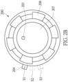
- control interface 200 provides the mode-switching switch 204, and the design and functions of the mode-switching switch 204 can be referred to in the schematic diagram of Fig. 2B .
- the control interface 200 is disposed on a housing of the body-wearable camera.
- the control interface 200 includes the first indication light 203, the main switch 207, the wheel switch 206, and the mode-switching switch 204.
- the mode-switching switch 204 is such as a switching mechanism used to switch the multiple operation-indication modes of the device.
- the switching mechanism can be switched to multiple gear positions.
- the switching mechanism as shown in the diagram can be a lever that is able to be switched to the multiple gear positions for being selectively connected with any of the signal terminals that are electrically connected with the control unit of the device.
- the device provides three gear positions through a design of a switching structure and multiple signal terminals.
- the three gear positions respectively correspond to different operation-indication modes via signals.
- the operation-indication mode switching structure and the circuit are able to perform switching so that the device operates under a first operation-indication mode S 1, a second operation-indication mode S2, or a third operation-indication mode S3.
- the three operation-indication modes include a covert mode 431, a stealth mode 433, and a normal mode 435.
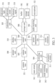
- a control unit 401 of the device determines to turn on or turn off an indication light 411, an indication sound 413, a vibration signal 415, and a display unit 417 based on any of the operation-indication modes, so as to show the operating status of the device through the indication functions.
- the control unit 401 is used to control a software component 407 and a circuit component 405 of the device.
- the control unit 401 is electrically connected with a mode-switching switch 403 that has the above-described operation-indication mode switching structure.
- the user can manipulate the operation-indication mode switching structure to any of the gear positions as shown in the diagram according to needs.
- the mode-switching switch 403 generates an operation-indication mode switching signal.
- the mode-switching switch 403 can be a magnetic-controlled switch that is used to conduct or short-circuit a switch of a specific circuit according to a magnetic field formed in the device by an electric power, by which the operation-indication mode switching signal is generated.
- the control unit 401 of the device When the control unit 401 of the device receives a signal that is generated when the mode-switching switch 403 being implemented by the switching mechanism conducts or short-circuits one of the multiple signal terminals, the signal forms the operation-indication mode switching signal that is configured to correspond to a first operation-indication mode S 1, a second operation-indication mode S2, and a third operation-indication mode S3. The control unit 401 then determines one of the multiple operation-indication modes according to the operation-indication mode switching signal and performs a corresponding indication function of the device.
- a user when the device is required to operate with a covert effect, a user can manipulate the mode-switching switch to switch to a position of the first operation-indication mode S 1 that leads to the covert mode 431.
- a terminal contact of the operation-indication mode switching structure Under the covert mode 431, a terminal contact of the operation-indication mode switching structure generates a signal when the terminal contact is conducted or short-circuited.
- the control unit 401 then turns off all of the indication functions of the device after receiving the signal under the covet mode 431. For example, under the covert mode 431, the device is completely covert when the indication light 411 is turned off, the indication sound 413 is muted, the vibration signal 415 is turned off, and a display of the display unit 417 of the device is also turned off.
- the device also provides the stealth mode 433.
- the device is switched to the stealth mode 433 when the user manipulates the mode-switching switch to switch to a position of the second operation-indication mode S2.
- the terminal contact of the operation-indication mode switching structure generates a signal when the terminal contact is conducted or short-circuited.
- the control unit 401 only turns off part of the multiple indication functions when receiving the signal. For example, under the stealth mode 433, the indication sound 413 and the indication light 411 are turned off, but the functions of the display of the display unit 417 and the vibration signal 415 are still turned on.
- control unit 401 If the user manipulates the mode-switching switch to switch to the gear position of the third operation-indication mode S3, the control unit 401 operates the device under the normal mode 435 according to a signal generated by the terminal contact of the operation-indication mode switching structure. Accordingly, the control unit 401 turns on all of the indication functions of the device.
- Fig. 5 shows a flowchart illustrating the operating method for the operation-indication modes according to one embodiment of the present disclosure.
- the camera continues to operate after being powered on (step S501), and then the various indication functions with the lights, vibration, sounds and displayed contents are selectively activated when any of the operation-indication modes of the device is read (step S503).
- the control unit receives the operation-indication mode switching signal (step S505) and one of the operation-indication modes is correspondingly determined based on the setting in the control unit (step S507).
- One or more of the operation-indication functions is then turned on or off according to the selected operation-indication mode (step S509).
- the body-wearable camera is continuously in operation.
- the operation-indication mode switching structure can be implemented by a button, a rotatable wheel, or a lever disposed on the device.
- the device embodies multiple operation-indication modes through the operation-indication mode switching structure that allows the operation-indication function of the device to be controlled by the control circuit under a covert mode, a stealth mode, and a normal mode.
- the operation-indication modes can be applied to the body-wearable camera worn by a policeman or a security that performs a specialized or an emergency mission.
Landscapes
- Engineering & Computer Science (AREA)
- Physics & Mathematics (AREA)
- Human Computer Interaction (AREA)
- Theoretical Computer Science (AREA)
- Multimedia (AREA)
- Signal Processing (AREA)
- General Physics & Mathematics (AREA)
- Health & Medical Sciences (AREA)
- Acoustics & Sound (AREA)
- Audiology, Speech & Language Pathology (AREA)
- Computational Linguistics (AREA)
- General Engineering & Computer Science (AREA)
- Computer Hardware Design (AREA)
- Quality & Reliability (AREA)
- Studio Devices (AREA)
- Telephone Function (AREA)
- User Interface Of Digital Computer (AREA)
- Signal Processing For Digital Recording And Reproducing (AREA)
- Television Signal Processing For Recording (AREA)
- Closed-Circuit Television Systems (AREA)
- Slide Switches (AREA)
- Input From Keyboards Or The Like (AREA)
- Switches With Compound Operations (AREA)
- Traffic Control Systems (AREA)
Abstract
Description
- The present disclosure relates to a technology of indicating operations of a switching device, and more particularly to a switching structure, a circuit and an operating method for the switching device that can be operated under operation-indication modes with various hidden indication functions.
- It is common for an electronic device to provide various indication functions such as light-emitting diode (LED) lights to indicate an operating status of the electronic device. For example, the LED lights can be used to indicate a current operating status of the electronic device through a constant light, a flashing light, a breathing light, or a color-changing light. The electronic device can also use a buzzer or a speaker to produce sounds having a specific frequency or a specific volume for indicating a current operating status of the electronic device. Further, the electronic device can use a vibration to indicate a current operating status, or the electronic device can include a display screen that can be used to show an operating status of the electronic device through a text or a pattern displayed on the display screen.
- However, when the electronic device is required to be operated under an extremely quiet environment or to be hidden under a covert mode, the above-mentioned indication functions will cause unwanted disturbance. For example, when a person wearing the device needs to secretly conduct a specific task, the above-mentioned indication functions such as the lights, vibration, sound, or luminosity of the display screen may expose the person's location.
- For an electronic device to operate while hiding all or part of operation-indication functions, the present disclosure provides a structure and a circuit allowing a user to conveniently manipulate to switch operation-indication modes. For example, in an audiovisual recording device, when the audiovisual recording device is in operation, the structure and the circuit for switching the operation-indication functions disposed in the audiovisual recording device allow the user to instantly switch to one of multiple operation-indication modes for indicating the operation of the audiovisual recording device when needed.
- In one aspect of the present disclosure, an operation-indication mode switching structure is disposed on a housing of the device. The switching structure includes a switching mechanism that is used to switch the multiple operation-indication modes of the device. The switching mechanism is used to be selectively connected with one of multiple signal terminals in the device. The signal terminals are electrically connected with a control unit of the device. According to an operation performed by the user or a determination executed by the device, when the control unit receives an operation-indication mode switching signal generated by the signal terminal that is conducted or short-circuited by the switching mechanism, the operation-indication mode switching signal corresponds to one of the multiple operation-indication modes, and the control unit controls multiple indication functions according to one of the multiple operation-indication modes to be switched to.
- Preferably, the switching mechanism achieves switching the operation-indication mode in an electrical manner or in a mechanical manner. For example, the switching mechanism can be a lever for being switched to one of multiple positions, so as to conduct or to short-circuit one of the multiple signal terminals.
- Preferably, the indication functions of the device include one or more indication lights, an indication sound, a vibration signal, and displaying an operating status of the device via a display unit.
- Further, according to one of the embodiments, the operation-indication modes include a covert mode, a stealth mode, and a normal mode. In one embodiment of the present disclosure, under the covert mode, the control unit turns off all of the indication functions of the device; under the stealth mode, the control unit turns off part of the indication functions of the device; and, under the normal mode, the control unit turns on all of the indication functions of the device.
- In one embodiment of the operation-indication mode switching circuit of the present disclosure, the switching circuit mainly includes a control unit and a mode-switching switch. The mode-switching switch includes the operation-indication mode switching structure.
- Further, according to certain embodiments of the operating method of the operation-indication mode switching circuit, when the device is in operation, the control unit turns on multiple operation-indication functions. The control unit determines a corresponding one of the multiple operation-indication modes when the control unit receives the operation-indication mode switching signal that is generated when the user manipulates the operation-indication mode switching structure to switch to one of the operation-indication modes. The control unit turns on or off one or more of the multiple operation-indication functions according to the corresponding one of the multiple operation-indication modes.
- These and other aspects of the present disclosure will become apparent from the following description of the embodiment taken in conjunction with the following drawings and their captions, although variations and modifications therein may be affected without departing from the spirit and scope of the novel concepts of the disclosure.
- The described embodiments may be better understood by reference to the following description and the accompanying drawings, in which:
-
Fig. 1 is a schematic diagram illustrating a framework of a body-wearable camera and a system applying the body-wearable camera according to one embodiment of the present disclosure; -
Fig. 2A andFig. 2B are schematic diagrams illustrating a structure of the body-wearable camera according to one embodiment of the present disclosure; -
Fig. 3 is a schematic diagram illustrating various internal components of the body-wearable camera according to one embodiment of the present disclosure; -
Fig. 4 is a schematic diagram depicting an operation-indication mode switching structure that is used to switch multiple operation-indication modes in one embodiment of the present disclosure; and -
Fig. 5 is a flowchart illustrating a method for operating switching operation-indication modes according to one embodiment of the present disclosure. - The present disclosure is more particularly described in the following examples that are intended as illustrative only since numerous modifications and variations therein will be apparent to those skilled in the art. Like numbers in the drawings indicate like components throughout the views. As used in the description herein and throughout the claims that follow, unless the context clearly dictates otherwise, the meaning of "a," "an" and "the" includes plural reference, and the meaning of "in" includes "in" and "on." Titles or subtitles can be used herein for the convenience of a reader, which shall have no influence on the scope of the present disclosure.
- The terms used herein generally have their ordinary meanings in the art. In the case of conflict, the present document, including any definitions given herein, will prevail. The same thing can be expressed in more than one way. Alternative language and synonyms can be used for any term(s) discussed herein, and no special significance is to be placed upon whether a term is elaborated or discussed herein. A recital of one or more synonyms does not exclude the use of other synonyms. The use of examples anywhere in this specification including examples of any terms is illustrative only, and in no way limits the scope and meaning of the present disclosure or of any exemplified term. Likewise, the present disclosure is not limited to various embodiments given herein. Numbering terms such as "first," "second" or "third" can be used to describe various components, signals or the like, which are for distinguishing one component/signal from another one only, and are not intended to, nor should be construed to impose any substantive limitations on the components, signals or the like.
- The present disclosure is related to an operation-indication mode switching structure, a circuit, and an operating method thereof. One of the functions of the operation-indication mode switching structure is to control an operation-indication function that indicates a current operation mode of a device. In addition to several practical operation modes operated in the device, the operation-indication mode switching structure, the circuit, and the operating method are provided for the device to be operable under various modes for concealing the indication functions.
- For example, the device can be operated under a covert mode or a stealth mode. One of the scenarios of application is to apply the covert mode or the stealth mode to a body-wearable camera that is worn by a specialized person such as a policeman or a security that needs to collect evidence at any time. The body-wearable camera can be worn on the chest of the person, or disposed on a safety helmet, a steel helmet or glasses of the person. In addition to the requisite functions of videography (e.g., audio and video recording, noise reduction, high image quality, and wide viewing angle) and storage, the body-wearable camera provides additional features such as long time operation (e.g., providing a large capacity battery), a power-saving mode, a black-box function of long-term continuous video recording for evidence collection, indication functions with a display screen, lights, and sounds, a data-encryption function, a communication function (e.g., mobile communication, Bluetooth®, or Wi-Fi®), integration in a digital video recorder (DVR), an emergency alerting function, having various sensors (e.g., a GPS circuit, an accelerometer, and/or a gyroscope), a robust structure that is waterproof, dustproof, and shockproof, and multiple manipulation functions by using buttons, a lever, and/or a rotatable wheel, etc.
- A system adopting the body-wearable camera is described as follows. The body-wearable camera can be used in conjunction with a control center for remote positioning, live video streaming, remote controlling (e.g., remotely initiate recording), emergency notification, contacting service crews, and operating with an application of a mobile device.
- A device that adopts the operation-indication mode switching structure of the present disclosure can be referred to in a schematic diagram of
Fig. 1 , which is a schematic diagram illustrating a framework of a body-wearable camera and a system applying the body-wearable camera according to one embodiment of the present disclosure. - In
Fig. 1 , a body-wearable camera 20 is such as a device worn by a person for recording and collecting surrounding evidences through video and sound. The body-wearable camera 20 is required to record the video in full. The operating status of the body-wearable camera 20 can be information such as a battery level or a memory capacity, or can be a state of the camera such as recording, recording being stopped, or recording a critical video that can be indicated by various indication lights, an indication sound, a vibration signal, and/or displaying an operating status of the device via a display unit. - According to one embodiment of the present disclosure, the body-
wearable camera 20 is capable of communicating with acontrol center 101, so that the person wearing the body-wearable camera 20 can communicate with thecontrol center 101 at any time. Furthermore, the body-wearable camera 20 can be remotely controlled by thecontrol center 101. For example, thecontrol center 101 can remotely control an operation mode of the body-wearable camera 20. Further, thecontrol center 101 can provide a livestream video via the body-wearable camera 20. - The body-
wearable camera 20 can be locally connected with a digital video recorder (DVR) 103. Thedigital video recorder 103 is a device with mass storage and multiple transmission terminals, and thedigital video recorder 103 is able to connect with multiple cameras so as to store the video data generated by the multiple cameras. Thus, when the body-wearable camera 20 is in operation, a recorded video can be transmitted to thedigital video recorder 103 in real-time or with a backup file that is produced later. On the other hand, the body-wearable camera 20 may further have a network transmission function that can disconnect from or connect with acloud data server 105 for transmitting the video to thecloud data server 105. - The body-
wearable camera 20 has a terminal that is able to transmit data and used for charging as connecting with acharging device 107 via a charging interface with a specific format. The terminal can also be used in conjunction with anotherdevice 109. For example, the body-wearable camera 20 worn by a soldier or a policeman can be coupled with a gun armed by the soldier or the policeman, so that the body-wearable camera 20 can be activated to start recording for evidence collection if a sensor senses that the gun is drawn by the soldier or the policeman. - Under a normal mode of the body-
wearable camera 20, various operation-indication functions such as lights, a sound, a vibration, and a content to be displayed can be used to indicate an operating status of the body-wearable camera 20. However, these indication functions may expose locations of a person performing a covert mission and cause the mission to fail. Therefore, it is necessary to conveniently and immediately set a covert mode to turn off the operation-indication functions. - Reference is made to
Fig. 2A andFig. 2B , which are schematic diagrams illustrating a structure of the body-wearable camera according to one embodiment of the present disclosure. -
Fig. 2A is a schematic diagram illustrating an exterior structure of the body-wearable camera 20 in one embodiment of the present disclosure. The body-wearable camera 20 includes acontrol interface 200 that provides various control functions. Thecontrol interface 200 is used to control operational functions of the body-wearable camera 20 in a mechanical manner or in an electrical manner. It should be noted that the embodiments are only used to illustrate a main operation interface and prompting functions of the body-wearable camera 20, and it is not meant to limit a practical implementation of the present disclosure. - According to one embodiment of the present disclosure, the body-
wearable camera 20 includes acamera lens 205 that is disposed on the exterior structure of the body-wearable camera 20. The body-wearable camera 20 includes a circuit for image retrieving and processing for capturing a video. The body-wearable camera 20 has aspeaker outlet 208 that is connected with an internal circuit for audio processing and outputting a voice and a sound. The body-wearable camera 20 includes amicrophone 202 that is connected with an internal circuit for audio receiving and processing, so as to record surrounding sounds. The body-wearable camera 20 also includes adisplay 210 that can be an LED display or an OLED display. Thedisplay 210 is used to indicate an operating status of the device by using texts or graphics. The body-wearable camera 20 includes asocket interface 209 that is used to connect with an external device or a power source. - Furthermore, the body-
wearable camera 20 provides acontrol interface 200 that implements a multi-functional switch through a mechanical design. As shown in the diagram of the present disclosure, thecontrol interface 200 includes amain switch 207, awheel switch 206, and a mode-switchingswitch 204. Themain switch 207 of thecontrol interface 200 allows a user to touch or press themain switch 207 for activating the device to start or stop recording. Apower switch 201 that is electrically connected with an internal power-management circuit is provided for turning on or turning off the body-wearable camera 20. Asecond indication light 211 can be used to indicate the operating status of the device by emitting light signals. The body-wearable camera 20 supports a function of power-on recording. That is, the body-wearable camera 20 starts recording when themain switch 207 is pressed, until the device is turned off, or recording is stopped. According to one embodiment of the present disclosure, thepower switch 201 can also be used to activate or shutdown a network connection function of the device. - According an exemplary example shown in the diagram, the body-
wearable camera 20 provides one or more indication lights such as the aforementionedsecond indication light 211 and afirst indication light 203 displayed on thecontrol interface 200. The indication lights can be implemented by LEDs that can be used to indicate the user the operating status of the device by lighting up the lights, turning off the lights, flashing the lights, or changing colors of the lights. The aforementionedfirst indication light 203 and thesecond indication light 211 can be used in conjunction for indicating a recording status, a charging status, a memory usage status, and a status of the device being turned on or off. - According to one embodiment shown in the diagram of the present disclosure, the
control interface 200 includes thewheel switch 206 that is provided for the user to switch to different functions by rotating thewheel switch 206 in clockwise or counterclockwise directions. Thewheel switch 206 can be used to mechanically set up multiple rotation gear positions, and thewheel switch 206 uses a magnetic-controlled switch that can be switched to any of the multiple rotation gear positions. Each of the rotation gear positions is connected with a specific circuit terminal. A signal is generated when any of the rotation gear positions is conducted, and the control unit of the body-wearable camera 20 can determine a corresponding function. - One of the functions of the
wheel switch 206 is that, the user can rotate thewheel switch 206 to select one of the categories of a video clip when the device is in operation. The video clip may be categorized to a specific category for future reference when a video file is created after the recording is stopped. For example, the category of the video clip can be set as an accident when the user determines that the instant scene is an accident scene. Accordingly, the user can rotate thewheel switch 206 to a gear position of an accident event. At this time, a prompting sound is output via aspeaker outlet 208. The video is set as an accident event when the video is stored. The category of the video can be an emergency event, and therefore thewheel switch 206 can be rotated to set the category of the recorded video as the emergency event when it is determined that the event is an emergency event. Similarly, the category of the video can be a violence event, and therefore thewheel switch 206 can be rotated to set the category of the recorded video as the violence event when it is determined that a violence event such as robbery has occurred. Further, the category of the video can be a speeding event, and therefore thewheel switch 206 can be rotated to a gear position of the speeding event when the user determines that the category of the recorded video is a speeding event. Therefore, the category of the recorded video is set as the speeding event. Still further, the category of the video can be a disturbance event, and therefore thewheel switch 206 is rotated to a gear position of the disturbance event when it is determined that the video is about a disturbance event such as a public protest. Further, the category of the video can be an arrest event, and therefore thewheel switch 206 is rotated to a gear position of the arrest event when it is determined that the video is about an arrest event. Accordingly, the video is categorized as an arrest event. - The functions of the device as shown in
Fig. 2A can be referred to inFig. 3 , which is a schematic diagram illustrating various internal components of the device. The blocks shown in the diagram can be circuit components and software components. As shown in the diagram, acontrol unit 300 of the device is provided for controlling operations of the device. Thecontrol unit 300 can be implemented by a microcontroller inside a body-wearable camera, and other circuit components are electrically connected with thecontrol unit 300. - The device can be a portable device that is powered by a battery. The device includes a power-
management unit 301 that is electrically connected with thecontrol unit 300 for managing the power supplied to the device, and the power-management unit 301 is also electrically connected with asocket connector 312. The device is preferably an audiovisual recorder that includes an audio-receivingunit 302 for receiving external audio by amicrophone 321, and acamera unit 305 for capturing images through acamera lens 351. Adisplay unit 310 of the device is used to display operating status of the device. Aspeaker unit 308 of the device is used to output a prompting sound. - The device includes a
storage unit 306. Thestorage unit 306 includes astorage device 362 for storing audiovisual data. Thestorage device 362 can be implemented by a non-volatile memory such as a flash memory or a solid state drive (SSD). Furthermore, thestorage unit 306 includes abuffer 361 for buffering the audiovisual data when the device is used for video recording. - According to one embodiment of the present disclosure, for the
buffer 361, the body-wearable camera can be a portable video recorder that is worn by a soldier, a policeman, or a person performing a specific task. One of the objectives of the video recorder is to collect a full audiovisual data at critical moments without losing any critical image. The completeness of the audiovisual data needs to be guaranteed so that the audiovisual data can be effective evidences. In addition to power requirement, the device is required to have the function of long-term video recording. Thestorage unit 306 can be implemented by software and firmware operating in the circuit, or a collaboration of software and hardware, so as to continuously record a video. A storage medium can be a random access memory (RAM) or other memories of a circuit system. Furthermore, the storage medium can be implemented by thebuffer 361. According to one embodiment of the present disclosure, when the device continuously receives the data (e.g., a video, an audio, or a combination thereof) via thecamera unit 305 and the audio-receivingunit 302, the data can be sequentially buffered to thebuffer 361 in a first-in-first-out (FIFO) manner, and then stored to thestorage device 362 according to an instruction. Alternatively, the data can directly form a livestream video that is transmitted to thecontrol center 101 as shown inFig. 1 . - Further, the device includes an
indication unit 303 that allows the user to acknowledge the operating status of the device by a displayed image, lights, or sounds. The various indication functions are controlled by circuits or software. For example, anindication light 331 can be implemented by LEDs, anindication sound 332 can be generated by a buzzer or a speaker, and avibration signal 333 can be generated by an internal vibrator. - In the diagram, the device provides various switches to control operations of the device. For example, a
switching unit 304 electrically connected with thecontrol unit 300 generates a signal that allows thecontrol unit 300 to decide an operation mode of the device. References are made to bothFig. 2A andFig. 2B , in which theswitching unit 304 includes anactuation switch 311, amain switch 341, a wheel-switchingswitch 342, and a mode-switchingswitch 343 that can be implemented in a mechanical manner or in an electrical manner. - In an exemplary example, when a user presses the
actuation switch 311, theswitching unit 304 generates a power-on signal that is provided to thecontrol unit 300 so as to drive the power-management unit 301 to power on the device. The user can also manipulate themain switch 341 to immediately start to record a video. The device can generate thevibration signal 333 or the indication sound 332 (e.g., a beep sound) for indicating that the device is booting up. The device can use a color of theindication light 331 or flashing of theindication light 331 to indicate that the device is recording. When the power supplied to the operating device drops to a low threshold, theindication light 331 is used to indicate a power state of the device with a specific color or a flashing light. The various operating statuses of the device can also be indicated for the user by a pattern or a text displayed on thedisplay unit 310. However, the above-mentioned lights, sounds, or displayed content may cause disturbance when the locations of the user is required to be hidden. Accordingly, the operation-indication mode switching structure and the circuit are provided. - According to one embodiment of the present disclosure, the above-described
control interface 200 provides the mode-switchingswitch 204, and the design and functions of the mode-switchingswitch 204 can be referred to in the schematic diagram ofFig. 2B . - As shown in the diagram, the
control interface 200 is disposed on a housing of the body-wearable camera. Thecontrol interface 200 includes thefirst indication light 203, themain switch 207, thewheel switch 206, and the mode-switchingswitch 204. The mode-switchingswitch 204 is such as a switching mechanism used to switch the multiple operation-indication modes of the device. The switching mechanism can be switched to multiple gear positions. For example, the switching mechanism as shown in the diagram can be a lever that is able to be switched to the multiple gear positions for being selectively connected with any of the signal terminals that are electrically connected with the control unit of the device. - Further, according to the schematic diagrams shown in
Fig. 2B andFig. 4 , the device provides three gear positions through a design of a switching structure and multiple signal terminals. The three gear positions respectively correspond to different operation-indication modes via signals. The operation-indication mode switching structure and the circuit are able to perform switching so that the device operates under a first operation-indication mode S 1, a second operation-indication mode S2, or a third operation-indication mode S3. The three operation-indication modes include acovert mode 431, astealth mode 433, and anormal mode 435. Acontrol unit 401 of the device determines to turn on or turn off anindication light 411, anindication sound 413, avibration signal 415, and adisplay unit 417 based on any of the operation-indication modes, so as to show the operating status of the device through the indication functions. - Therefore, according to the embodiment shown in
Fig. 4 , thecontrol unit 401 is used to control asoftware component 407 and acircuit component 405 of the device. Thecontrol unit 401 is electrically connected with a mode-switchingswitch 403 that has the above-described operation-indication mode switching structure. The user can manipulate the operation-indication mode switching structure to any of the gear positions as shown in the diagram according to needs. Afterwards, the mode-switchingswitch 403 generates an operation-indication mode switching signal. According to one of the embodiments of the present disclosure, the mode-switchingswitch 403 can be a magnetic-controlled switch that is used to conduct or short-circuit a switch of a specific circuit according to a magnetic field formed in the device by an electric power, by which the operation-indication mode switching signal is generated. - When the
control unit 401 of the device receives a signal that is generated when the mode-switchingswitch 403 being implemented by the switching mechanism conducts or short-circuits one of the multiple signal terminals, the signal forms the operation-indication mode switching signal that is configured to correspond to a first operation-indication mode S 1, a second operation-indication mode S2, and a third operation-indication mode S3. Thecontrol unit 401 then determines one of the multiple operation-indication modes according to the operation-indication mode switching signal and performs a corresponding indication function of the device. - According to one embodiment of the present disclosure, when the device is required to operate with a covert effect, a user can manipulate the mode-switching switch to switch to a position of the first operation-
indication mode S 1 that leads to thecovert mode 431. Under thecovert mode 431, a terminal contact of the operation-indication mode switching structure generates a signal when the terminal contact is conducted or short-circuited. Thecontrol unit 401 then turns off all of the indication functions of the device after receiving the signal under thecovet mode 431. For example, under thecovert mode 431, the device is completely covert when theindication light 411 is turned off, theindication sound 413 is muted, thevibration signal 415 is turned off, and a display of thedisplay unit 417 of the device is also turned off. - The device also provides the
stealth mode 433. The device is switched to thestealth mode 433 when the user manipulates the mode-switching switch to switch to a position of the second operation-indication mode S2. The terminal contact of the operation-indication mode switching structure generates a signal when the terminal contact is conducted or short-circuited. Thecontrol unit 401 only turns off part of the multiple indication functions when receiving the signal. For example, under thestealth mode 433, theindication sound 413 and theindication light 411 are turned off, but the functions of the display of thedisplay unit 417 and thevibration signal 415 are still turned on. - If the user manipulates the mode-switching switch to switch to the gear position of the third operation-indication mode S3, the
control unit 401 operates the device under thenormal mode 435 according to a signal generated by the terminal contact of the operation-indication mode switching structure. Accordingly, thecontrol unit 401 turns on all of the indication functions of the device. -
Fig. 5 then shows a flowchart illustrating the operating method for the operation-indication modes according to one embodiment of the present disclosure. - Taking recording a livestream video by the body-wearable camera as an example, the camera continues to operate after being powered on (step S501), and then the various indication functions with the lights, vibration, sounds and displayed contents are selectively activated when any of the operation-indication modes of the device is read (step S503).
- Then, when the user manipulates the operation-indication mode switching structure to switch the mode-switching switch to one of the operation-indication modes, the control unit receives the operation-indication mode switching signal (step S505) and one of the operation-indication modes is correspondingly determined based on the setting in the control unit (step S507). One or more of the operation-indication functions is then turned on or off according to the selected operation-indication mode (step S509). In each of the operation-indication modes, the body-wearable camera is continuously in operation.
- In conclusion, according to the abovementioned embodiments relating to the operation-indication mode switching structure, the circuit, and the operating method of the present disclosure, the operation-indication mode switching structure can be implemented by a button, a rotatable wheel, or a lever disposed on the device. The device embodies multiple operation-indication modes through the operation-indication mode switching structure that allows the operation-indication function of the device to be controlled by the control circuit under a covert mode, a stealth mode, and a normal mode. In particular, the operation-indication modes can be applied to the body-wearable camera worn by a policeman or a security that performs a specialized or an emergency mission. In addition to continuously performing high-quality video evidence collection, it is necessary to conceal the operation-indication functions of the device in order to avoid affecting the mission.
- The foregoing description of the exemplary embodiments of the disclosure has been presented only for the purposes of illustration and description and is not intended to be exhaustive or to limit the disclosure to the precise forms disclosed. Many modifications and variations are possible in light of the above teaching.
- The embodiments were chosen and described in order to explain the principles of the disclosure and their practical application so as to enable others skilled in the art to utilize the disclosure and various embodiments and with various modifications as are suited to the particular use contemplated. Alternative embodiments will become apparent to those skilled in the art to which the present disclosure pertains without departing from its spirit and scope.
Claims (15)
- An operation-indication mode switching structure, disposed on a housing of a device, characterized in that the structure comprises:a switching mechanism used to switch multiple operation-indication modes (S1, S2, S3) of the device for being selectively connected with one of multiple signal terminals, wherein the multiple signal terminals are connected with a control unit (300);wherein the control unit (300) receives an operation-indication mode switching signal generated by one of the multiple signal terminals conducted or short-circuited by the switching mechanism, and wherein the operation-indication mode switching signal corresponds to one of the multiple operation-indication modes (S1, S2, S3), and the control unit (300) controls multiple indication functions of the device according to one of the multiple operation-indication modes (S 1, S2, S3) to be switched to.
- The operation-indication mode switching structure according to claim 1, characterized in that the multiple operation-indication modes (S1, S2, S3) include a covert mode (431), a stealth mode (433), and a normal mode (435).
- The operation-indication mode switching structure according to claim 2, characterized in that, under the covert mode (431), the control unit (300) turns off all of the indication functions of the device; under the stealth mode (433), the control unit (300) turns off part of the indication functions of the device; and, under the normal mode (435), the control unit (300) turns on all of the indication functions of the device.
- The operation-indication mode switching structure according to claim 1, characterized in that the switching mechanism is a lever for being switched to one of multiple positions so as to conduct or short-circuit one of the multiple signal terminals.
- The operation-indication mode switching structure according to claim 4, characterized in that the multiple operation-indication modes (S1, S2, S3) include a covert mode (431), a stealth mode (433), and a normal mode (435).
- The operation-indication mode switching structure according to claim 1, characterized in that the indication functions of the device include one or more indication lights, an indication sound, a vibration signal, and displaying an operating status of the device via a display unit (310).
- The operation-indication mode switching structure according to claim 6, characterized in that the multiple operation-indication modes (S1, S2, S3) include a covert mode (431), a stealth mode (433), and a normal mode (435).
- The operation-indication mode switching structure according to claim 7, characterized in that, under the covert mode (431), the control unit (300) turns off all of the indication functions of the device; under the stealth mode (433), the control unit (300) turns off part of the indication functions of the device; and, under the normal mode (435), the control unit (300) turns on all of the indication functions of the device.
- An operation-indication mode switching circuit, characterized in that the circuit comprises:a control unit (300); anda mode-switching switch (204) electrically connected with the control unit (300), wherein the mode-switching switch (204) includes an operation-indication mode switching structure, the operation-indication mode switching structure is disposed on a housing of a device, and the operation-indication mode switching structure includes:a switching mechanism used to switch multiple operation-indication mode of the device, wherein the switching mechanism is selectively connected with one of the multiple signal terminals, and the multiple signal terminals are connected with the control unit (300) of the device;wherein the control unit (300) receives an operation-indication mode switching signal generated by one of the signal terminals conducted or short-circuited by the switching mechanism, and wherein the operation-indication mode switching signal corresponds to one of the multiple operation-indication modes (S 1, S2, S3), and the control unit (300) controls multiple indication functions of the device according to one of the multiple operation-indication modes (S 1, S2, S3) to be switched.
- The operation-indication mode switching circuit according to claim 9, characterized in that the multiple operation-indication modes (S1, S2, S3) include a covert mode (431), a stealth mode (433), and a normal mode (435).
- The operation-indication mode switching circuit according to claim 9, characterized in that the switching mechanism is a lever for being switched to one of the multiple positions so as to conduct or short-circuit one of the multiple signal terminals.
- The operation-indication mode switching circuit according to claim 11, characterized in that the multiple operation-indication modes (S1, S2, S3) include a covert mode (431), a stealth mode (433), and a normal mode (435).
- The operation-indication mode switching circuit according to claim 9, characterized in that the indication functions of the device include one or more indication lights, an indication sound, a vibration signal, and displaying an operating status of the device via a display unit (310).
- The operation-indication mode switching circuit according to claim 13, characterized in that the multiple operation-indication modes (S1, S2, S3) include a covert mode (431), a stealth mode (433) and a normal mode (435).
- An operating method for the operation-indication mode switching circuit, wherein the operation-indication mode switching circuit is disposed in the device, characterized in that the operating method includes:during an operation of the device, turning on multiple operation-indication functions by using the control unit (300);determining a corresponding one of the multiple operation-indication modes (S1, S2, S3) when the control unit (300) receives the operation-indication mode switching signal; andturning on or off one or more of the multiple operation-indication functions according to the corresponding one of the multiple operation-indication modes (S1, S2, S3).
Applications Claiming Priority (2)
| Application Number | Priority Date | Filing Date | Title |
|---|---|---|---|
| US202263423453P | 2022-11-07 | 2022-11-07 | |
| US202363449272P | 2023-03-01 | 2023-03-01 |
Publications (1)
| Publication Number | Publication Date |
|---|---|
| EP4365705A1 true EP4365705A1 (en) | 2024-05-08 |
Family
ID=86604778
Family Applications (4)
| Application Number | Title | Priority Date | Filing Date |
|---|---|---|---|
| EP23175301.3A Pending EP4365892A1 (en) | 2022-11-07 | 2023-05-25 | Voice activity detection device and method |
| EP23188628.4A Pending EP4365705A1 (en) | 2022-11-07 | 2023-07-31 | Operation-indication mode switching structure, circuit and method for operating the same |
| EP23189417.1A Pending EP4365893A1 (en) | 2022-11-07 | 2023-08-03 | Body-worn camera and operation method thereof |
| EP23202395.2A Pending EP4365899A1 (en) | 2022-11-07 | 2023-10-09 | Memory management method for continuously recording digital content and circuit system thereof |
Family Applications Before (1)
| Application Number | Title | Priority Date | Filing Date |
|---|---|---|---|
| EP23175301.3A Pending EP4365892A1 (en) | 2022-11-07 | 2023-05-25 | Voice activity detection device and method |
Family Applications After (2)
| Application Number | Title | Priority Date | Filing Date |
|---|---|---|---|
| EP23189417.1A Pending EP4365893A1 (en) | 2022-11-07 | 2023-08-03 | Body-worn camera and operation method thereof |
| EP23202395.2A Pending EP4365899A1 (en) | 2022-11-07 | 2023-10-09 | Memory management method for continuously recording digital content and circuit system thereof |
Country Status (3)
| Country | Link |
|---|---|
| US (5) | US12393334B2 (en) |
| EP (4) | EP4365892A1 (en) |
| TW (5) | TWI852489B (en) |
Families Citing this family (3)
| Publication number | Priority date | Publication date | Assignee | Title |
|---|---|---|---|---|
| TWI852489B (en) * | 2022-11-07 | 2024-08-11 | 神基科技股份有限公司 | Voice activity detection device and method |
| US20250251902A1 (en) * | 2024-02-07 | 2025-08-07 | SuperScope Technologies Inc. | Record Check |
| JP7665249B1 (en) * | 2024-10-25 | 2025-04-21 | Matsuo Sangyoグループ株式会社 | Camera System |
Citations (5)
| Publication number | Priority date | Publication date | Assignee | Title |
|---|---|---|---|---|
| US9232134B2 (en) * | 2011-11-29 | 2016-01-05 | Olympus Corporation | Imaging device |
| US20160196693A1 (en) * | 2015-01-06 | 2016-07-07 | Seiko Epson Corporation | Display system, control method for display device, and computer program |
| US20160227173A1 (en) * | 2015-01-29 | 2016-08-04 | Panasonic Intellectual Property Management Co., Ltd. | Wearable camera system, and video recording control method for wearable camera system |
| US9661283B2 (en) * | 2014-12-24 | 2017-05-23 | Panasonic Intellectual Property Management Co., Ltd. | Wearable camera |
| US10446183B2 (en) * | 2008-04-06 | 2019-10-15 | Taser International, Inc. | Systems and methods for a recorder user interface |
Family Cites Families (58)
| Publication number | Priority date | Publication date | Assignee | Title |
|---|---|---|---|---|
| JPH0675588A (en) | 1992-08-27 | 1994-03-18 | Fujitsu Ltd | Speech recognition device |
| US5418762A (en) * | 1992-12-09 | 1995-05-23 | Sony Corporation | Optical disk recording device having a pre-recording mode |
| US6519003B1 (en) | 1998-03-26 | 2003-02-11 | Eastman Kodak Company | Camera with combination four-way directional and mode control interface |
| US6563532B1 (en) * | 1999-01-05 | 2003-05-13 | Internal Research Corporation | Low attention recording unit for use by vigorously active recorder |
| US7155735B1 (en) | 1999-10-08 | 2006-12-26 | Vulcan Patents Llc | System and method for the broadcast dissemination of time-ordered data |
| JP4101421B2 (en) | 1999-12-27 | 2008-06-18 | 富士フイルム株式会社 | INPUT UNIT, INFORMATION RECORDING DEVICE USING INPUT UNIT, AND DIGITAL CAMERA |
| JP4620894B2 (en) * | 2001-04-06 | 2011-01-26 | キヤノン株式会社 | Electronics |
| US6957397B1 (en) * | 2001-06-11 | 2005-10-18 | Palm, Inc. | Navigating through a menu of a handheld computer using a keyboard |
| TWI225369B (en) * | 2003-03-18 | 2004-12-11 | Jin-Shu Chen | Diversified video recording apparatus |
| US20040212637A1 (en) | 2003-04-22 | 2004-10-28 | Kivin Varghese | System and Method for Marking and Tagging Wireless Audio and Video Recordings |
| US7023004B2 (en) | 2003-10-23 | 2006-04-04 | Timothy Ford | Multi-mode electromagnetic radiation emitting device |
| US20050147397A1 (en) * | 2003-12-17 | 2005-07-07 | Sony Corporation | Image pickup apparatus |
| KR20050090798A (en) | 2004-03-10 | 2005-09-14 | 삼성전자주식회사 | Switching apparatus of photographing device for selecting mode |
| JP4379800B2 (en) * | 2004-07-12 | 2009-12-09 | ソニー・エリクソン・モバイルコミュニケーションズ株式会社 | Receiving apparatus and memory releasing method thereof |
| JP2006040382A (en) * | 2004-07-27 | 2006-02-09 | Sony Corp | Digital data recording apparatus and recording method |
| TWI245191B (en) * | 2004-09-14 | 2005-12-11 | Ali Corp | Sound receiving and pre-recording device and method |
| US20060085834A1 (en) * | 2004-10-19 | 2006-04-20 | Cayin Technology Co., Ltd. | System and method for transmitting multi-channel signals |
| US9209995B2 (en) * | 2006-12-29 | 2015-12-08 | Prodea Systems, Inc. | Presence status notification from digital endpoint devices through a multi-services gateway device at the user premises |
| US8140325B2 (en) * | 2007-01-04 | 2012-03-20 | International Business Machines Corporation | Systems and methods for intelligent control of microphones for speech recognition applications |
| US8209728B2 (en) | 2007-08-31 | 2012-06-26 | At&T Intellectual Property I, L.P. | System and method of delivering video content |
| JP5075664B2 (en) * | 2008-02-15 | 2012-11-21 | 株式会社東芝 | Spoken dialogue apparatus and support method |
| US8872940B2 (en) * | 2008-03-03 | 2014-10-28 | Videoiq, Inc. | Content aware storage of video data |
| TWI402718B (en) * | 2008-07-01 | 2013-07-21 | Inventec Corp | Electronic device and operation method thereof |
| US10737185B2 (en) * | 2009-03-18 | 2020-08-11 | Microsoft Technology Licensing, Llc | Virtual environment controls based on voice chat audio inputs |
| ES2903148T3 (en) | 2010-09-13 | 2022-03-31 | Contour Ip Holding Llc | Portable digital video camera configured for remote image acquisition control and viewing |
| JP5189221B1 (en) * | 2012-03-13 | 2013-04-24 | シャープ株式会社 | CONTENT DISPLAY DEVICE, TELEVISION RECEIVER, MENU SCREEN GENERATION METHOD, PROGRAM, AND RECORDING MEDIUM |
| TW201414274A (en) * | 2012-09-21 | 2014-04-01 | Hon Hai Prec Ind Co Ltd | Sound effect managing system and sound effect managing method |
| US9019431B2 (en) * | 2012-09-28 | 2015-04-28 | Digital Ally, Inc. | Portable video and imaging system |
| US20140104493A1 (en) * | 2012-10-11 | 2014-04-17 | Tangome, Inc. | Proactive video frame dropping for hardware and network variance |
| US9706101B2 (en) * | 2012-10-22 | 2017-07-11 | Sony Corporation | Image processing terminal, imaging machine, information processing method, program, and remote imaging system to remotely operate the imaging machine |
| US9329833B2 (en) * | 2013-12-20 | 2016-05-03 | Dell Products, L.P. | Visual audio quality cues and context awareness in a virtual collaboration session |
| TWI516950B (en) | 2013-12-23 | 2016-01-11 | 勝捷光電股份有限公司 | System and method for sharing real-time recording |
| KR102164798B1 (en) | 2014-09-11 | 2020-10-13 | 삼성전자 주식회사 | Display driving circuit and display device comprising the same |
| WO2016088919A1 (en) * | 2014-12-04 | 2016-06-09 | (주) 트라이너스 | Wireless microphone system |
| US20160286156A1 (en) | 2015-02-12 | 2016-09-29 | Creative Law Enforcement Resources, Inc. | System for managing information related to recordings from video/audio recording devices |
| TWI550612B (en) | 2015-03-23 | 2016-09-21 | 群聯電子股份有限公司 | Data programming method, memory storage device and memory controlling circuit unit |
| CN105045473A (en) * | 2015-07-01 | 2015-11-11 | 沈波 | Human-computer interaction system and method |
| CN105120063A (en) | 2015-07-13 | 2015-12-02 | 联想(北京)有限公司 | Volume prompting method of input voice and electronic device |
| US20170094231A1 (en) * | 2015-09-29 | 2017-03-30 | Faraday&Future Inc. | Scene reconstruction using pre-buffering in sensor triggered automobile cameras |
| US9697884B2 (en) * | 2015-10-08 | 2017-07-04 | Rambus Inc. | Variable width memory module supporting enhanced error detection and correction |
| US10812894B2 (en) | 2016-12-23 | 2020-10-20 | Motorola Solutions, Inc. | Portable communication device and method of operating the same in covert operation mode |
| JP6553111B2 (en) * | 2017-03-21 | 2019-07-31 | 株式会社東芝 | Speech recognition apparatus, speech recognition method and speech recognition program |
| JP6894736B2 (en) * | 2017-03-24 | 2021-06-30 | キヤノン株式会社 | Recording device, control method, and program |
| CN107291341B (en) * | 2017-07-11 | 2021-03-09 | 广州飞傲电子科技有限公司 | Method and system for selecting music player through touch turntable rotation |
| CN109548080B (en) * | 2017-08-11 | 2023-05-16 | 夏普株式会社 | Related method, user equipment and base station for media access control layer grouping |
| CN108320742B (en) * | 2018-01-31 | 2021-09-14 | 广东美的制冷设备有限公司 | Voice interaction method, intelligent device and storage medium |
| US20190266881A1 (en) | 2018-02-25 | 2019-08-29 | Laura Gasparis Vonfrolio | System and method for an alert and crisis/emergency management system |
| CN108668017A (en) | 2018-04-19 | 2018-10-16 | Oppo广东移动通信有限公司 | Volume prompting method, mode switching method, device, terminal and storage medium |
| CN110750491A (en) | 2018-07-06 | 2020-02-04 | 神讯电脑(昆山)有限公司 | Setting method of information capture device |
| CN110858493A (en) | 2018-08-23 | 2020-03-03 | 神讯电脑(昆山)有限公司 | information capture device |
| CN110881076A (en) * | 2018-09-06 | 2020-03-13 | 上海伴我科技有限公司 | Terminal communication device |
| TW202113561A (en) * | 2019-09-20 | 2021-04-01 | 和碩聯合科技股份有限公司 | Notebook computer and operation method thereof |
| US11490204B2 (en) * | 2020-07-20 | 2022-11-01 | Apple Inc. | Multi-device audio adjustment coordination |
| JP2022022152A (en) * | 2020-07-24 | 2022-02-03 | シンクウェア コーポレーション | Electronic device and method for determining lifespan and failure of nonvolatile memory storage device |
| TW202205143A (en) | 2020-07-30 | 2022-02-01 | 杰悉科技股份有限公司 | Image object labeling method |
| US11489996B2 (en) * | 2021-03-31 | 2022-11-01 | Johnny Burton | Wireless earpiece camera apparatus |
| US11950017B2 (en) * | 2022-05-17 | 2024-04-02 | Digital Ally, Inc. | Redundant mobile video recording |
| TWI852489B (en) * | 2022-11-07 | 2024-08-11 | 神基科技股份有限公司 | Voice activity detection device and method |
-
2023
- 2023-04-20 TW TW112114808A patent/TWI852489B/en active
- 2023-05-16 US US18/318,649 patent/US12393334B2/en active Active
- 2023-05-25 EP EP23175301.3A patent/EP4365892A1/en active Pending
- 2023-06-07 TW TW112121198A patent/TWI882349B/en active
- 2023-06-07 TW TW112121192A patent/TWI832774B/en active
- 2023-07-11 US US18/350,707 patent/US12353710B2/en active Active
- 2023-07-18 US US18/354,552 patent/US12554396B2/en active Active
- 2023-07-31 EP EP23188628.4A patent/EP4365705A1/en active Pending
- 2023-08-03 EP EP23189417.1A patent/EP4365893A1/en active Pending
- 2023-08-08 TW TW112129654A patent/TWI841470B/en active
- 2023-10-09 EP EP23202395.2A patent/EP4365899A1/en active Pending
- 2023-10-11 US US18/484,594 patent/US12360668B2/en active Active
- 2023-11-07 TW TW112142737A patent/TWI906690B/en active
-
2025
- 2025-06-27 US US19/252,206 patent/US20250328241A1/en active Pending
Patent Citations (5)
| Publication number | Priority date | Publication date | Assignee | Title |
|---|---|---|---|---|
| US10446183B2 (en) * | 2008-04-06 | 2019-10-15 | Taser International, Inc. | Systems and methods for a recorder user interface |
| US9232134B2 (en) * | 2011-11-29 | 2016-01-05 | Olympus Corporation | Imaging device |
| US9661283B2 (en) * | 2014-12-24 | 2017-05-23 | Panasonic Intellectual Property Management Co., Ltd. | Wearable camera |
| US20160196693A1 (en) * | 2015-01-06 | 2016-07-07 | Seiko Epson Corporation | Display system, control method for display device, and computer program |
| US20160227173A1 (en) * | 2015-01-29 | 2016-08-04 | Panasonic Intellectual Property Management Co., Ltd. | Wearable camera system, and video recording control method for wearable camera system |
Non-Patent Citations (1)
| Title |
|---|
| MARION KOELLE ET AL: "Beyond LED Status Lights - Design Requirements of Privacy Notices for Body-worn Cameras", TANGIBLE, EMBEDDED, AND EMBODIED INTERACTION, ACM, 2 PENN PLAZA, SUITE 701NEW YORKNY10121-0701USA, 9 March 2018 (2018-03-09), pages 177 - 187, XP058387410, ISBN: 978-1-4503-5568-1, DOI: 10.1145/3173225.3173234 * |
Also Published As
| Publication number | Publication date |
|---|---|
| US12393334B2 (en) | 2025-08-19 |
| US20240153719A1 (en) | 2024-05-09 |
| US12360668B2 (en) | 2025-07-15 |
| TWI832774B (en) | 2024-02-11 |
| TW202420296A (en) | 2024-05-16 |
| EP4365892A1 (en) | 2024-05-08 |
| EP4365893A1 (en) | 2024-05-08 |
| TW202420219A (en) | 2024-05-16 |
| TWI882349B (en) | 2025-05-01 |
| US20240152273A1 (en) | 2024-05-09 |
| EP4365899A1 (en) | 2024-05-08 |
| TW202420038A (en) | 2024-05-16 |
| TWI906690B (en) | 2025-12-01 |
| US20240155082A1 (en) | 2024-05-09 |
| US20240153530A1 (en) | 2024-05-09 |
| TW202420042A (en) | 2024-05-16 |
| TWI841470B (en) | 2024-05-01 |
| TWI852489B (en) | 2024-08-11 |
| US12353710B2 (en) | 2025-07-08 |
| TW202420801A (en) | 2024-05-16 |
| US12554396B2 (en) | 2026-02-17 |
| US20250328241A1 (en) | 2025-10-23 |
Similar Documents
| Publication | Publication Date | Title |
|---|---|---|
| US12554396B2 (en) | Operation-indication mode switching structure, circuit and method for operating the same | |
| US20240177584A1 (en) | Instant video alert notifier | |
| JP2001045669A (en) | Warning device and method of complex electronic equipment | |
| JP2007259329A (en) | Remote control device, system and method | |
| JP2010278962A (en) | Imaging apparatus and program | |
| CN101257620A (en) | Real-time video and audio monitoring device and controller and monitoring method thereof | |
| US20120176470A1 (en) | Non-Handheld High-Definition Digital Video Camera | |
| US20120249758A1 (en) | Electric apparatus and control method of indicator | |
| KR20040016530A (en) | Digital camera and method for preventing hidden picture-taking | |
| CN109547722B (en) | Law enforcement recording method, storage medium, control device and law enforcement recorder | |
| CN117998200A (en) | Operation indication mode switching structure, circuit and operation method thereof | |
| US20100231776A1 (en) | Personal protection device with wireless audio-visual transmission | |
| CN117579737A (en) | Vehicle pet mode control system, method, device and storage medium | |
| JP7494000B2 (en) | Worker terminal, work support system | |
| CN116453282A (en) | Alarm control system, method, equipment and storage medium | |
| JP2011049653A (en) | Image capturing apparatus | |
| CN209358657U (en) | Audio-video law-enforcing recorder | |
| JP2004078011A (en) | Digital camera | |
| US7616860B2 (en) | Methods and apparatuses for displaying content through a storage device | |
| KR100380073B1 (en) | Dual camera system for vehicles and method for controlling the same | |
| CN109963054B (en) | Image recording equipment | |
| JP2009171447A (en) | Camera, image display control method, image display control program, recording medium | |
| CN205430466U (en) | Intercom law enforcement record appearance | |
| JP2005229538A (en) | Digital camera system | |
| RU2374781C2 (en) | Underwater television control system |
Legal Events
| Date | Code | Title | Description |
|---|---|---|---|
| PUAI | Public reference made under article 153(3) epc to a published international application that has entered the european phase |
Free format text: ORIGINAL CODE: 0009012 |
|
| STAA | Information on the status of an ep patent application or granted ep patent |
Free format text: STATUS: THE APPLICATION HAS BEEN PUBLISHED |
|
| AK | Designated contracting states |
Kind code of ref document: A1 Designated state(s): AL AT BE BG CH CY CZ DE DK EE ES FI FR GB GR HR HU IE IS IT LI LT LU LV MC ME MK MT NL NO PL PT RO RS SE SI SK SM TR |
|
| STAA | Information on the status of an ep patent application or granted ep patent |
Free format text: STATUS: REQUEST FOR EXAMINATION WAS MADE |
|
| 17P | Request for examination filed |
Effective date: 20241025 |
|
| RBV | Designated contracting states (corrected) |
Designated state(s): AL AT BE BG CH CY CZ DE DK EE ES FI FR GB GR HR HU IE IS IT LI LT LU LV MC ME MK MT NL NO PL PT RO RS SE SI SK SM TR |
|
| STAA | Information on the status of an ep patent application or granted ep patent |
Free format text: STATUS: EXAMINATION IS IN PROGRESS |
|
| 17Q | First examination report despatched |
Effective date: 20251020 |