EP4365588A1 - Gas measurement device, gas measurement system, and gas measurement method - Google Patents
Gas measurement device, gas measurement system, and gas measurement method Download PDFInfo
- Publication number
- EP4365588A1 EP4365588A1 EP23207918.6A EP23207918A EP4365588A1 EP 4365588 A1 EP4365588 A1 EP 4365588A1 EP 23207918 A EP23207918 A EP 23207918A EP 4365588 A1 EP4365588 A1 EP 4365588A1
- Authority
- EP
- European Patent Office
- Prior art keywords
- filter
- gas
- terminals
- voltage
- current
- Prior art date
- Legal status (The legal status is an assumption and is not a legal conclusion. Google has not performed a legal analysis and makes no representation as to the accuracy of the status listed.)
- Granted
Links
Images



Classifications
-
- G—PHYSICS
- G01—MEASURING; TESTING
- G01N—INVESTIGATING OR ANALYSING MATERIALS BY DETERMINING THEIR CHEMICAL OR PHYSICAL PROPERTIES
- G01N33/00—Investigating or analysing materials by specific methods not covered by groups G01N1/00 - G01N31/00
- G01N33/0004—Gaseous mixtures, e.g. polluted air
- G01N33/0009—General constructional details of gas analysers, e.g. portable test equipment
- G01N33/0011—Sample conditioning
- G01N33/0014—Sample conditioning by eliminating a gas
-
- G—PHYSICS
- G01—MEASURING; TESTING
- G01N—INVESTIGATING OR ANALYSING MATERIALS BY DETERMINING THEIR CHEMICAL OR PHYSICAL PROPERTIES
- G01N33/00—Investigating or analysing materials by specific methods not covered by groups G01N1/00 - G01N31/00
- G01N33/0004—Gaseous mixtures, e.g. polluted air
- G01N33/0009—General constructional details of gas analysers, e.g. portable test equipment
- G01N33/0011—Sample conditioning
-
- G—PHYSICS
- G01—MEASURING; TESTING
- G01N—INVESTIGATING OR ANALYSING MATERIALS BY DETERMINING THEIR CHEMICAL OR PHYSICAL PROPERTIES
- G01N1/00—Sampling; Preparing specimens for investigation
- G01N1/02—Devices for withdrawing samples
- G01N1/22—Devices for withdrawing samples in the gaseous state
- G01N1/2202—Devices for withdrawing samples in the gaseous state involving separation of sample components during sampling
- G01N1/2205—Devices for withdrawing samples in the gaseous state involving separation of sample components during sampling with filters
-
- B—PERFORMING OPERATIONS; TRANSPORTING
- B01—PHYSICAL OR CHEMICAL PROCESSES OR APPARATUS IN GENERAL
- B01D—SEPARATION
- B01D46/00—Filters or filtering processes specially modified for separating dispersed particles from gases or vapours
- B01D46/10—Particle separators, e.g. dust precipitators, using filter plates, sheets or pads having plane surfaces
-
- B—PERFORMING OPERATIONS; TRANSPORTING
- B01—PHYSICAL OR CHEMICAL PROCESSES OR APPARATUS IN GENERAL
- B01D—SEPARATION
- B01D46/00—Filters or filtering processes specially modified for separating dispersed particles from gases or vapours
- B01D46/66—Regeneration of the filtering material or filter elements inside the filter
- B01D46/74—Regeneration of the filtering material or filter elements inside the filter by forces created by movement of the filter element
- B01D46/76—Regeneration of the filtering material or filter elements inside the filter by forces created by movement of the filter element involving vibrations
-
- G—PHYSICS
- G01—MEASURING; TESTING
- G01N—INVESTIGATING OR ANALYSING MATERIALS BY DETERMINING THEIR CHEMICAL OR PHYSICAL PROPERTIES
- G01N1/00—Sampling; Preparing specimens for investigation
- G01N1/28—Preparing specimens for investigation including physical details of (bio-)chemical methods covered elsewhere, e.g. G01N33/50, C12Q
- G01N1/34—Purifying; Cleaning
-
- G—PHYSICS
- G01—MEASURING; TESTING
- G01N—INVESTIGATING OR ANALYSING MATERIALS BY DETERMINING THEIR CHEMICAL OR PHYSICAL PROPERTIES
- G01N27/00—Investigating or analysing materials by the use of electric, electrochemical, or magnetic means
- G01N27/02—Investigating or analysing materials by the use of electric, electrochemical, or magnetic means by investigating impedance
- G01N27/04—Investigating or analysing materials by the use of electric, electrochemical, or magnetic means by investigating impedance by investigating resistance
- G01N27/12—Investigating or analysing materials by the use of electric, electrochemical, or magnetic means by investigating impedance by investigating resistance of a solid body in dependence upon absorption of a fluid; of a solid body in dependence upon reaction with a fluid, for detecting components in the fluid
-
- G—PHYSICS
- G01—MEASURING; TESTING
- G01N—INVESTIGATING OR ANALYSING MATERIALS BY DETERMINING THEIR CHEMICAL OR PHYSICAL PROPERTIES
- G01N29/00—Investigating or analysing materials by the use of ultrasonic, sonic or infrasonic waves; Visualisation of the interior of objects by transmitting ultrasonic or sonic waves through the object
- G01N29/22—Details, e.g. general constructional or apparatus details
- G01N29/24—Probes
- G01N29/2437—Piezoelectric probes
-
- G—PHYSICS
- G01—MEASURING; TESTING
- G01N—INVESTIGATING OR ANALYSING MATERIALS BY DETERMINING THEIR CHEMICAL OR PHYSICAL PROPERTIES
- G01N29/00—Investigating or analysing materials by the use of ultrasonic, sonic or infrasonic waves; Visualisation of the interior of objects by transmitting ultrasonic or sonic waves through the object
- G01N29/34—Generating the ultrasonic, sonic or infrasonic waves, e.g. electronic circuits specially adapted therefor
- G01N29/348—Generating the ultrasonic, sonic or infrasonic waves, e.g. electronic circuits specially adapted therefor with frequency characteristics, e.g. single frequency signals, chirp signals
Definitions
- the present disclosure relates to a gas measurement device, a gas measurement system, and a gas measurement method.
- Japanese Patent Application Publication No. 2000-249644 discloses a gas measurement device.
- the gas measurement device includes a Langmuir-Blodgett membrane (hereinafter, referred to as an LB membrane) and a gas sensor for detecting molecules passing through the LB membrane. Since the LB membrane adsorbs certain gas molecules, the gas sensor selectively detects only the sifted molecules.
- LB membrane Langmuir-Blodgett membrane
- a gas measurement device includes a filter unit and a gas sensor.
- the filter unit includes a plurality of terminals configured to be applied a voltage or a current and a filter configured to vibrate in response to the voltage or the current being applied to the plurality of terminals.
- the gas sensor detects gas molecules that have passed through the filter and outputs a measurement value corresponding to the detected gas molecules.
- the filter of the filter unit vibrates in response to application of voltage or current to a plurality of terminals of the filter unit.
- the filter allows gas molecules having a size corresponding to mesh of the filter to pass through.
- the gas molecules passing through the filter are detected by a gas sensor, and a measurement value is output.
- Gas molecules larger than the mesh of the filter cannot pass through the filter and tend to stay so as to block the mesh of the filter.
- the filter repels gas molecules that are about to stay by vibration, and prevents the mesh of the filter from being blocked. Therefore, the gas measurement device can suppress deterioration of the gas molecule sieving function.
- the gas measurement device can easily recover the sieving function.
- the gas measurement device may include a plurality of filter units including a filter unit, wherein the plurality of filter units may be disposed to overlap each other.
- the gas measurement device can realize high-accuracy screening by adopting a multistage filter.
- a pulse voltage may be applied to the plurality of terminals
- the filter unit may include a piezoelectric element electrically connected to the plurality of terminals
- the filter may be supported by the piezoelectric element.
- the filter may realize vibration through which gas molecules having a size of a detection target may pass by a piezoelectric element that expands and contracts according to a pulse voltage.
- the current may be applied to the plurality of terminals
- the filter unit may include a metal member electrically connected to the plurality of terminals
- the filter may be supported by the metal member.
- the free electrons collide with the atom, causing lattice vibrations, which are transmitted to the filter.
- the filter can realize vibration through which gas molecules having a size of a detection target can pass by using the above-described vibration principle.
- a gas measurement system includes a gas measurement device and a control unit.
- the gas measurement device includes a filter unit and a gas sensor.
- the filter unit includes a plurality of terminals configured to be applied a voltage or a current and a filter configured to vibrate in response to the voltage or the current being applied to the plurality of terminals.
- the gas sensor detects gas molecules that have passed through the filter and outputs a measurement value corresponding to the detected gas molecules.
- the control unit applies the voltage or the current to the plurality of terminals such that the filter vibrates at a predetermined frequency.
- the filter of the filter unit vibrates at a predetermined frequency in response to application of the voltage or the current to the plurality of terminals of the filter unit.
- the filter allows gas molecules having a size corresponding to mesh of the filter to pass through.
- the gas molecules passing through the filter are detected by a gas sensor, and a measurement value is output.
- Gas molecules larger than the mesh of the filter cannot pass through the filter and tend to stay so as to block the mesh of the filter.
- the filter repels gas molecules that are about to stay by vibration, and prevents the mesh of the filter from being blocked. Therefore, the gas measurement device can suppress deterioration of the gas molecule sieving function.
- the gas measurement system can easily recover the sieving function.
- a gas measurement method includes the following steps.
- FIG. 1 is a cross-sectional view illustrating an example of a gas measurement system according to an embodiment.
- a gas measurement system 1 shown in FIG. 1 includes a gas measurement device 10.
- the gas measurement device 10 measures the composition of the gas.
- the gas measurement device 10 may be provided as an electrical circuit component.
- the gas measurement device 10 is MEMS (Micro Electro Mechanical Systems) devices.
- the gas measurement device 10 comprises a filter unit 11 and a gas sensor 12.
- the filter unit 11 has the function of sieving gas molecules.
- the filter unit 11 is supported on a substrate 13.
- the substrate 13 defines a space therein.
- the substrate 13 is formed of a material impermeable to gas.
- the substrate 13 is open at an upper portion thereof and has an opening communicating with the space.
- the filter unit 11 is positioned to block the opening in the upper portion of the substrate 13.
- the filter unit 11 and the substrate 13 thereby define a gas chamber 14.
- the gas sensor 12 is placed in the gas chamber 14.
- the gas sensor 12 detects the gas molecules that permeate the filter unit 11 and are supplied to the gas chamber 14.
- the gas sensor 12 outputs a measurement value in response to the detected gas molecules.
- a semiconductor method is used as an example.
- the detection mode of the gas sensor 12 gas molecules may be an electrochemical mode, a quartz crystal mode or a surface-acoustic-wave mode.
- the measurement value output by the gas sensor 12 is a change in voltage due to a change in resistance value.
- the gas measurement device 10 can measure gas components contained in the detected gas based on the measurement value.
- the filtering function of the filter unit 11 gas molecules is maintained in performance by the vibration of the filter.
- a power supply 20 is connected to the filter unit 11, and a voltage or current is applied according to a command of a control unit 30.
- the filter unit 11 In response to the application of voltage or current, the filter unit 11 filter vibrates at predetermined frequencies.
- the term "vibrate” refers to periodic operation. The detailed configuration of the filter unit 11 will be described later.
- the control unit 30 is configured as, for example, a programmable logic controller (PLC).
- the control unit 30 may be configured as a computer system including a processor such as a central processing unit (CPU), memories such as a random-access memory (RAM) and a read only memory (ROM), input/output devices such as a touch panel, a mouse, a keyboard, and a display, and a communication device such as a network card.
- the control unit 30 realizes the function of the control unit 30 by operating each hardware under the control of the processor based on the computer program stored in the memory.
- the control unit 30 has a memory that pre-stores the relationship between the size or type of gas molecules and the frequencies of the filters.
- the control unit 30 consults the memory to determine the frequencies corresponding to the gas molecules to be detected.
- the control unit 30 controls the power supply 20 to apply a voltage or current to the filter unit 11 such that the filter vibrates at the determined frequencies.
- the control unit 30 may have a memory that pre-stores the association between the size or type of gas molecules and voltage or current. In this case, the control unit 30 determines the voltage or current with reference to the memory and controls the power supply 20 such that the determined voltage or current is applied to the filter unit 11.
- the control unit 30 may control not only frequencies but also amplitudes.
- FIG. 2 is a perspective view showing an example of the filter unit.
- the filter unit 11 shown in FIG. 2 is employed when the power supply 20 is the voltage source and the control unit 30 controls the power supply 20 to supply voltage to the filter unit 11.
- the filter unit 11 includes a plurality of terminals 110, a filter 111, and a piezoelectric element 112.
- the plurality of the terminals 110 is formed of conductive metals.
- the plurality of the terminals 110 is, for example, four.
- the power supply 20 is connected to the plurality of the terminals 110, and a pulse voltage is applied thereto.
- piezoelectric elements 112 are prepared.
- the piezoelectric elements 112 are arranged parallel to each other.
- the plurality of the terminals 110 is provided at both ends of each of the piezoelectric elements 112 and is electrically connected. When a pulse voltage is applied, each of the piezoelectric elements 112 expands and contracts according to the magnitude of the voltage.
- the filter 111 is provided so as to be bridged between two piezoelectric elements 112.
- the filter 111 is comb-shaped. When two piezoelectric elements 112 are driven, the filter 111 vibrates at predetermined frequencies in the up-down direction (or left-right direction).
- the filter 111 may be made of metals such as aluminum (Al) or gold (Au), or non-metals such as resins or hard fibers.
- FIG. 3 is a perspective view showing another example of the filter unit.
- a filter unit 11A shown in FIG. 3 is employed when the power supply 20 is the current source and the control unit 30 controls the power supply 20 to supply current to the filter unit 11.
- the filter unit 11 includes a plurality of the terminals 110, the filter 111, and a metal member 112A.
- the plurality of the terminals 110 is formed of conductive metals.
- the plurality of the terminals 110 is, for example, four.
- the power supply 20 is connected to the plurality of the terminals 110, and current is applied thereto.
- two metal members 112A are prepared.
- the metal members 112A are arranged parallel to each other.
- the plurality of the terminals 110 is provided at both ends of each of the metal members 112A and is electrically connected.
- Each of the metal members 112A vibrates when a current is applied.
- current is applied to the metal members 112A, free electrons move inside the metal members 112A and collide with the atom, causing lattice vibration.
- the filter 111 is provided so as to be bridged between two metal members 112A.
- the shape and material of the filter 111 are identical to those of the filter 111 shown in FIG. 2 . Vibration of two metal members 112A propagates to the filter 111.
- the filter 111 vibrates at predetermined frequencies in an up-down direction (or left-right direction).
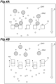
- FIGS. 4A and 4B are a diagram illustrating an example of the principle of a filter.
- a first gas GA1 is assumed to be detection target gas. It is assumed that the first gas GA1 is mixed with a second gas GA2 having a larger molecular size.
- FIG. 4A schematically shows a filter cross section in a state where no current or voltage is applied. As shown in FIG. 4A , it is assumed that the gas mixture moves in the direction indicated by an arrow D in the figure and reaches the filter unit 11. The filter 111 is at rest because no current or voltage is applied. The first gas GA1 smaller than the mesh of the filter 111 passes through the filter 111, while the second gas GA2 larger than the mesh of the filter 111 does not pass through the filter 111 and remain.
- FIG. 4B schematically shows a cross section of the filter in a state where a current or a voltage is applied. Since current or voltage is applied to the filter 111, the gap is in a vibration state. For example, each the filter 111 vibrates in an up-down direction as indicated by the dashed arrow in the figure. Thus, the retained the second gas GA2 is flicked off. In this way, the occurrence of clogging of the filter 111 is suppressed.
- FIG. 5 is a flowchart illustrating an example of a gas measurement method according to an embodiment.
- the gas chamber 14 Prior to performing the gas measurement method shown in FIG. 5 , the gas chamber 14 is pumped to a vacuum. Alternatively, the atmosphere of the gas chamber 14 is replaced with a gas such as nitrogen or a rare gas.
- step S10 the control unit 30 vibrates the filter 111 at predetermined frequencies.
- the control unit 30 controls the power supply 20 and causes a current or voltage to be applied to the filter unit 11.
- step S12 the gas mixture is supplied to the gas measurement device 10.
- the gas sensor 12 detects gas molecules that have passed through the vibrated the filter 111 and outputs a measurement value corresponding to the detected gas molecules.
- the gas measurement method shown in FIG. 5 ends.
- the filter 111 of the filter unit 11 vibrates in response to the application of voltage or current to multiple the terminal 110 of the filter unit 11.
- the filter 111 passes gas molecules of a size corresponding to the mesh of the filter 111.
- the gas sensor 12 molecules that have passed through the filter 111 are detected in the gas, and a measurement value is output.
- Gas molecules that are larger than the mesh of the filter 111 cannot pass through the filter 111 and tend to lodge to block the mesh of the filter 111.
- the filter 111 repels the stagnating gas molecules by vibration to avoid blocking the mesh of the filter 111. Therefore, the gas measurement system 1 and the gas measurement device 10 can suppress a decrease in the gas molecule sieving function.
- the gas measurement system 1 and the gas measurement device 10 can remove large gas molecules by only sucking while vibrating the filter 111 even if clogging of the filter 111 occurs due to the gas molecules larger than the mesh of the filter 111. Thus, the gas measurement system 1 and the gas measurement device 10 can easily recover the sieving function.
- the filter 111 can be used in any usage environment without being limited by the detection method, shape, environment, and the like of the gas sensor 12. Since the filter 111 is not energized, breakage of the filter 111 due to electromigration or the like can be avoided. In addition, since the vibration is extremely fine, there is little possibility of breakage of the filter 111 due to the vibration.
- the voltage or current applied to the filter unit 11 is also weak, and a change in energy such as electricity, magnetism, or heat near the filter 111 is extremely small. Therefore, even when the filter 111 is placed in the vicinity of the gas sensor 12, there is no significant influence on the detection accuracy and the life of the gas sensor 12.
- the gas measurement device 10 may be configured to be free of the substrate 13 and the gas chamber 14.
- the gas measurement device 10 may be configured such that the filter unit 11 adheres to the gas sensor 12.
- the gas measurement system 1 may be free of the power supply 20.
- the filter 111 may be provided with additional functions as necessary.
- the filter 111 may be coated to prevent adhesion of gas molecules.
- the filter 111 may be coated such that certain gas molecules preferentially adhere thereto.
- the filter unit 11 may be installed in multiple stages. In this case, the plurality of filter units is arranged to overlap each other. When the mixed gas is filtered, all filter units are vibrated.
- the gas measurement device may comprise two stage filter units.
- the filter unit of the first stage (upper stage) may have a coarse mesh
- the filter unit of the second stage (lower stage) may have a mesh size that allows passage of the gas molecules to be detected.
- clogging is prevented by vibration while large gas molecules are removed by the first stage filter
- clogging of the second stage filter is more effectively prevented by preventing clogging of the second stage filter by vibration even by the second stage filter, so that desired gas can be detected.
- the gas measurement system 1 can transmit only gas components of extremely small molecules.
- the gas measurement system 1 can sieve only the desired gas with high accuracy.
- the gas measurement device 10 may have a structure in which the filter vibrates under the influence of vibration of a portion adjacent to the filter 111, or may have a structure in which the filter 111 itself vibrates.
- the shape of the filter 111 may be grid-like instead of comb-like.
- the vibration direction of the filter 111 is not limited to the up-down direction, and may be the left-right direction.
- the cross-section of the filter 111 may be circular, square, or any other geometric shape.
- the filter 111 may be attached to a printed circuit board.
Landscapes
- Chemical & Material Sciences (AREA)
- Health & Medical Sciences (AREA)
- Life Sciences & Earth Sciences (AREA)
- Pathology (AREA)
- Physics & Mathematics (AREA)
- Analytical Chemistry (AREA)
- Biochemistry (AREA)
- General Health & Medical Sciences (AREA)
- General Physics & Mathematics (AREA)
- Immunology (AREA)
- Engineering & Computer Science (AREA)
- Chemical Kinetics & Catalysis (AREA)
- Biomedical Technology (AREA)
- Molecular Biology (AREA)
- Combustion & Propulsion (AREA)
- Food Science & Technology (AREA)
- Medicinal Chemistry (AREA)
- Electrochemistry (AREA)
- Sampling And Sample Adjustment (AREA)
- Investigating Or Analyzing Materials By The Use Of Electric Means (AREA)
- Investigating Or Analyzing Materials By The Use Of Fluid Adsorption Or Reactions (AREA)
Abstract
Description
- This application is based on
Japanese Patent Application No. 2022-178251 filed with Japan Patent Office on November 7, 2022 - The present disclosure relates to a gas measurement device, a gas measurement system, and a gas measurement method.
-
Japanese Patent Application Publication No. 2000-249644 - In the gas sensor described in
Japanese Patent Application Publication No. 2000-249644 - A gas measurement device according to an aspect of the present disclosure includes a filter unit and a gas sensor. The filter unit includes a plurality of terminals configured to be applied a voltage or a current and a filter configured to vibrate in response to the voltage or the current being applied to the plurality of terminals. The gas sensor detects gas molecules that have passed through the filter and outputs a measurement value corresponding to the detected gas molecules.
- In the gas measurement device, the filter of the filter unit vibrates in response to application of voltage or current to a plurality of terminals of the filter unit. The filter allows gas molecules having a size corresponding to mesh of the filter to pass through. The gas molecules passing through the filter are detected by a gas sensor, and a measurement value is output. Gas molecules larger than the mesh of the filter cannot pass through the filter and tend to stay so as to block the mesh of the filter. The filter repels gas molecules that are about to stay by vibration, and prevents the mesh of the filter from being blocked. Therefore, the gas measurement device can suppress deterioration of the gas molecule sieving function. Further, even if clogging of the filter occurs due to gas molecules larger than the mesh of the filter, the large gas molecules clogged in the mesh of the filter can be removed only by sucking while vibrating the filter. Therefore, the gas measurement device can easily recover the sieving function.
- In an embodiment, the gas measurement device may include a plurality of filter units including a filter unit, wherein the plurality of filter units may be disposed to overlap each other. The gas measurement device can realize high-accuracy screening by adopting a multistage filter.
- In an embodiment, a pulse voltage may be applied to the plurality of terminals, the filter unit may include a piezoelectric element electrically connected to the plurality of terminals, and the filter may be supported by the piezoelectric element. The filter may realize vibration through which gas molecules having a size of a detection target may pass by a piezoelectric element that expands and contracts according to a pulse voltage.
- In one embodiment, the current may be applied to the plurality of terminals, the filter unit may include a metal member electrically connected to the plurality of terminals, and the filter may be supported by the metal member. When the current is applied to the metal member, the free electrons collide with the atom, causing lattice vibrations, which are transmitted to the filter. The filter can realize vibration through which gas molecules having a size of a detection target can pass by using the above-described vibration principle.
- According to another aspect of the present disclosure, a gas measurement system includes a gas measurement device and a control unit. The gas measurement device includes a filter unit and a gas sensor. The filter unit includes a plurality of terminals configured to be applied a voltage or a current and a filter configured to vibrate in response to the voltage or the current being applied to the plurality of terminals. The gas sensor detects gas molecules that have passed through the filter and outputs a measurement value corresponding to the detected gas molecules. The control unit applies the voltage or the current to the plurality of terminals such that the filter vibrates at a predetermined frequency.
- In this gas measurement system, the filter of the filter unit vibrates at a predetermined frequency in response to application of the voltage or the current to the plurality of terminals of the filter unit. The filter allows gas molecules having a size corresponding to mesh of the filter to pass through. The gas molecules passing through the filter are detected by a gas sensor, and a measurement value is output. Gas molecules larger than the mesh of the filter cannot pass through the filter and tend to stay so as to block the mesh of the filter. The filter repels gas molecules that are about to stay by vibration, and prevents the mesh of the filter from being blocked. Therefore, the gas measurement device can suppress deterioration of the gas molecule sieving function. Further, even if clogging of the filter occurs due to gas molecules larger than the mesh of the filter, the large gas molecules clogged in the mesh of the filter can be removed only by sucking while vibrating the filter. Therefore, the gas measurement system can easily recover the sieving function.
- A gas measurement method according to still another aspect of the present disclosure includes the following steps.
- (1) vibrating the filter;
- (2) detecting gas molecules that have passed through the vibrated filter, and outputting a measurement value corresponding to the detected gas molecules.
- According to this gas measurement method, the same effect as that of the above-described gas detector can be obtained.
- According to the present disclosure, it is possible to suppress a decrease in the gas molecule sieving function.
-
-
FIG. 1 is a cross-sectional view illustrating an example of a gas measurement system according to an embodiment. -
FIG. 2 is a perspective view showing an example of the filter unit. -
FIG. 3 is a perspective view showing another example of the filter unit. -
FIG. 4A is a diagram illustrating an example of the principle of a filter. -
FIG. 4B is a diagram illustrating an example of the principle of a filter. -
FIG. 5 is a flowchart illustrating an example of a gas measurement method according to an embodiment. - Hereinafter, embodiments of the present disclosure will be described with reference to the drawings. In the following description, the same or corresponding elements are denoted by the same reference numerals, and redundant description will not be repeated. The dimensional ratios in the drawings are not necessarily consistent with those in the description. The terms "up", "down", "left" and "right" are based on the illustrated state and are for convenience.
-
FIG. 1 is a cross-sectional view illustrating an example of a gas measurement system according to an embodiment. A gas measurement system 1 shown inFIG. 1 includes agas measurement device 10. Thegas measurement device 10 measures the composition of the gas. Thegas measurement device 10 may be provided as an electrical circuit component. As an example, thegas measurement device 10 is MEMS (Micro Electro Mechanical Systems) devices. Thegas measurement device 10 comprises afilter unit 11 and agas sensor 12. - The
filter unit 11 has the function of sieving gas molecules. Thefilter unit 11 is supported on asubstrate 13. Thesubstrate 13 defines a space therein. Thesubstrate 13 is formed of a material impermeable to gas. Thesubstrate 13 is open at an upper portion thereof and has an opening communicating with the space. Thefilter unit 11 is positioned to block the opening in the upper portion of thesubstrate 13. Thefilter unit 11 and thesubstrate 13 thereby define agas chamber 14. - The
gas sensor 12 is placed in thegas chamber 14. Thegas sensor 12 detects the gas molecules that permeate thefilter unit 11 and are supplied to thegas chamber 14. Thegas sensor 12 outputs a measurement value in response to the detected gas molecules. As a method of detecting gas molecules in thegas sensor 12, a semiconductor method is used as an example. The detection mode of thegas sensor 12 gas molecules may be an electrochemical mode, a quartz crystal mode or a surface-acoustic-wave mode. For example, in the case of a semiconductor sensor, the measurement value output by thegas sensor 12 is a change in voltage due to a change in resistance value. Thegas measurement device 10 can measure gas components contained in the detected gas based on the measurement value. - The filtering function of the
filter unit 11 gas molecules is maintained in performance by the vibration of the filter. Apower supply 20 is connected to thefilter unit 11, and a voltage or current is applied according to a command of acontrol unit 30. In response to the application of voltage or current, thefilter unit 11 filter vibrates at predetermined frequencies. The term "vibrate" refers to periodic operation. The detailed configuration of thefilter unit 11 will be described later. - The
control unit 30 is configured as, for example, a programmable logic controller (PLC). Thecontrol unit 30 may be configured as a computer system including a processor such as a central processing unit (CPU), memories such as a random-access memory (RAM) and a read only memory (ROM), input/output devices such as a touch panel, a mouse, a keyboard, and a display, and a communication device such as a network card. Thecontrol unit 30 realizes the function of thecontrol unit 30 by operating each hardware under the control of the processor based on the computer program stored in the memory. - The
control unit 30 has a memory that pre-stores the relationship between the size or type of gas molecules and the frequencies of the filters. Thecontrol unit 30 consults the memory to determine the frequencies corresponding to the gas molecules to be detected. Thecontrol unit 30 controls thepower supply 20 to apply a voltage or current to thefilter unit 11 such that the filter vibrates at the determined frequencies. Thecontrol unit 30 may have a memory that pre-stores the association between the size or type of gas molecules and voltage or current. In this case, thecontrol unit 30 determines the voltage or current with reference to the memory and controls thepower supply 20 such that the determined voltage or current is applied to thefilter unit 11. Thecontrol unit 30 may control not only frequencies but also amplitudes. -
FIG. 2 is a perspective view showing an example of the filter unit. Thefilter unit 11 shown inFIG. 2 is employed when thepower supply 20 is the voltage source and thecontrol unit 30 controls thepower supply 20 to supply voltage to thefilter unit 11. As shown inFIG. 2 , thefilter unit 11 includes a plurality ofterminals 110, afilter 111, and apiezoelectric element 112. The plurality of theterminals 110 is formed of conductive metals. The plurality of theterminals 110 is, for example, four. Thepower supply 20 is connected to the plurality of theterminals 110, and a pulse voltage is applied thereto. - Here, two
piezoelectric elements 112 are prepared. Thepiezoelectric elements 112 are arranged parallel to each other. The plurality of theterminals 110 is provided at both ends of each of thepiezoelectric elements 112 and is electrically connected. When a pulse voltage is applied, each of thepiezoelectric elements 112 expands and contracts according to the magnitude of the voltage. - The
filter 111 is provided so as to be bridged between twopiezoelectric elements 112. Thefilter 111 is comb-shaped. When twopiezoelectric elements 112 are driven, thefilter 111 vibrates at predetermined frequencies in the up-down direction (or left-right direction). Thefilter 111 may be made of metals such as aluminum (Al) or gold (Au), or non-metals such as resins or hard fibers. -
FIG. 3 is a perspective view showing another example of the filter unit. Afilter unit 11A shown inFIG. 3 is employed when thepower supply 20 is the current source and thecontrol unit 30 controls thepower supply 20 to supply current to thefilter unit 11. As shown inFIG. 3 , thefilter unit 11 includes a plurality of theterminals 110, thefilter 111, and ametal member 112A. The plurality of theterminals 110 is formed of conductive metals. The plurality of theterminals 110 is, for example, four. Thepower supply 20 is connected to the plurality of theterminals 110, and current is applied thereto. - Here, two
metal members 112A are prepared. Themetal members 112A are arranged parallel to each other. The plurality of theterminals 110 is provided at both ends of each of themetal members 112A and is electrically connected. Each of themetal members 112A vibrates when a current is applied. When current is applied to themetal members 112A, free electrons move inside themetal members 112A and collide with the atom, causing lattice vibration. - The
filter 111 is provided so as to be bridged between twometal members 112A. The shape and material of thefilter 111 are identical to those of thefilter 111 shown inFIG. 2 . Vibration of twometal members 112A propagates to thefilter 111. Thefilter 111 vibrates at predetermined frequencies in an up-down direction (or left-right direction). -
FIGS. 4A and 4B are a diagram illustrating an example of the principle of a filter. In the following description, a first gas GA1 is assumed to be detection target gas. It is assumed that the first gas GA1 is mixed with a second gas GA2 having a larger molecular size.FIG. 4A schematically shows a filter cross section in a state where no current or voltage is applied. As shown inFIG. 4A , it is assumed that the gas mixture moves in the direction indicated by an arrow D in the figure and reaches thefilter unit 11. Thefilter 111 is at rest because no current or voltage is applied. The first gas GA1 smaller than the mesh of thefilter 111 passes through thefilter 111, while the second gas GA2 larger than the mesh of thefilter 111 does not pass through thefilter 111 and remain. -
FIG. 4B schematically shows a cross section of the filter in a state where a current or a voltage is applied. Since current or voltage is applied to thefilter 111, the gap is in a vibration state. For example, each thefilter 111 vibrates in an up-down direction as indicated by the dashed arrow in the figure. Thus, the retained the second gas GA2 is flicked off. In this way, the occurrence of clogging of thefilter 111 is suppressed. -
FIG. 5 is a flowchart illustrating an example of a gas measurement method according to an embodiment. Prior to performing the gas measurement method shown inFIG. 5 , thegas chamber 14 is pumped to a vacuum. Alternatively, the atmosphere of thegas chamber 14 is replaced with a gas such as nitrogen or a rare gas. - As shown in
FIG. 5 , first, as a vibration process (step S10), thecontrol unit 30 vibrates thefilter 111 at predetermined frequencies. For example, thecontrol unit 30 controls thepower supply 20 and causes a current or voltage to be applied to thefilter unit 11. - Subsequently, as a detection process (step S12), the gas mixture is supplied to the
gas measurement device 10. Thegas sensor 12 detects gas molecules that have passed through the vibrated thefilter 111 and outputs a measurement value corresponding to the detected gas molecules. When the step S12 ends, the gas measurement method shown inFIG. 5 ends. - In the gas measurement system 1 and the
gas measurement device 10, thefilter 111 of thefilter unit 11 vibrates in response to the application of voltage or current to multiple theterminal 110 of thefilter unit 11. Thefilter 111 passes gas molecules of a size corresponding to the mesh of thefilter 111. Thegas sensor 12 molecules that have passed through thefilter 111 are detected in the gas, and a measurement value is output. Gas molecules that are larger than the mesh of thefilter 111 cannot pass through thefilter 111 and tend to lodge to block the mesh of thefilter 111. Thefilter 111 repels the stagnating gas molecules by vibration to avoid blocking the mesh of thefilter 111. Therefore, the gas measurement system 1 and thegas measurement device 10 can suppress a decrease in the gas molecule sieving function. - The gas measurement system 1 and the
gas measurement device 10 can remove large gas molecules by only sucking while vibrating thefilter 111 even if clogging of thefilter 111 occurs due to the gas molecules larger than the mesh of thefilter 111. Thus, the gas measurement system 1 and thegas measurement device 10 can easily recover the sieving function. - According to the gas measurement system 1 and the
gas measurement device 10, thefilter 111 can be used in any usage environment without being limited by the detection method, shape, environment, and the like of thegas sensor 12. Since thefilter 111 is not energized, breakage of thefilter 111 due to electromigration or the like can be avoided. In addition, since the vibration is extremely fine, there is little possibility of breakage of thefilter 111 due to the vibration. - The voltage or current applied to the
filter unit 11 is also weak, and a change in energy such as electricity, magnetism, or heat near thefilter 111 is extremely small. Therefore, even when thefilter 111 is placed in the vicinity of thegas sensor 12, there is no significant influence on the detection accuracy and the life of thegas sensor 12. - While various exemplary embodiments have been described above, various omissions, substitutions and changes may be made without being limited to the exemplary embodiments described above.
- The
gas measurement device 10 may be configured to be free of thesubstrate 13 and thegas chamber 14. In this case, thegas measurement device 10 may be configured such that thefilter unit 11 adheres to thegas sensor 12. The gas measurement system 1 may be free of thepower supply 20. - The
filter 111 may be provided with additional functions as necessary. For example, thefilter 111 may be coated to prevent adhesion of gas molecules. Alternatively, thefilter 111 may be coated such that certain gas molecules preferentially adhere thereto. - The
filter unit 11 may be installed in multiple stages. In this case, the plurality of filter units is arranged to overlap each other. When the mixed gas is filtered, all filter units are vibrated. For example, the gas measurement device may comprise two stage filter units. The filter unit of the first stage (upper stage) may have a coarse mesh, and the filter unit of the second stage (lower stage) may have a mesh size that allows passage of the gas molecules to be detected. In this case, clogging is prevented by vibration while large gas molecules are removed by the first stage filter, and clogging of the second stage filter is more effectively prevented by preventing clogging of the second stage filter by vibration even by the second stage filter, so that desired gas can be detected. By installing the filter units in multiple stages, the gas measurement system 1 can transmit only gas components of extremely small molecules. Thus, the gas measurement system 1 can sieve only the desired gas with high accuracy. - The
gas measurement device 10 may have a structure in which the filter vibrates under the influence of vibration of a portion adjacent to thefilter 111, or may have a structure in which thefilter 111 itself vibrates. The shape of thefilter 111 may be grid-like instead of comb-like. The vibration direction of thefilter 111 is not limited to the up-down direction, and may be the left-right direction. The cross-section of thefilter 111 may be circular, square, or any other geometric shape. Thefilter 111 may be attached to a printed circuit board.
Claims (6)
- A gas measurement device for measuring gas, comprising:a filter unit including a plurality of terminals configured to be applied a voltage or a current and a filter configured to vibrate in response to the voltage or the current being applied to the plurality of terminals; anda gas sensor configured to detect gas molecules passing through the filter and output a measurement value corresponding to the detected gas molecules.
- The gas measurement device according to claim 1, further comprising a plurality of filter units including the filter unit, wherein the plurality of filter units is disposed to overlap each other.
- The gas measurement device according to claim 1 or 2,
wherein a pulse voltage is applied to the plurality of terminals, and the filter unit includes a piezoelectric element electrically connected to the plurality of terminals, and the filter is supported by the piezoelectric element. - The gas measurement device according to claim 1 or 2,
wherein the current is applied to the plurality of terminals, and the filter unit includes a metal member electrically connected to the plurality of terminals, and the filter is supported by the metal member. - A gas measurement system for measuring gas, comprising:a gas measurement device comprising:a filter unit including a plurality of terminals configured to be applied a voltage or a current and a filter configured to vibrate in response to the voltage or the current being applied to the plurality of terminals; anda gas sensor configured to detect gas molecules passing through the filter and output a measurement value corresponding to the detected gas molecules; anda control unit configured to apply the voltage or the current to the plurality of terminals such that the filter vibrates at a predetermined frequency.
- A gas measurement method, comprising:vibrating a filter; anddetecting gas molecules that have passed through the vibrated filter and outputting a measurement value corresponding to the detected gas molecules.
Applications Claiming Priority (1)
| Application Number | Priority Date | Filing Date | Title |
|---|---|---|---|
| JP2022178251A JP2024067869A (en) | 2022-11-07 | 2022-11-07 | Gas measuring device, gas measuring system, and gas measuring method |
Publications (2)
| Publication Number | Publication Date |
|---|---|
| EP4365588A1 true EP4365588A1 (en) | 2024-05-08 |
| EP4365588B1 EP4365588B1 (en) | 2026-02-11 |
Family
ID=88697509
Family Applications (1)
| Application Number | Title | Priority Date | Filing Date |
|---|---|---|---|
| EP23207918.6A Active EP4365588B1 (en) | 2022-11-07 | 2023-11-06 | Gas measurement device, gas measurement system, and gas measurement method |
Country Status (4)
| Country | Link |
|---|---|
| US (1) | US12656228B2 (en) |
| EP (1) | EP4365588B1 (en) |
| JP (1) | JP2024067869A (en) |
| CN (1) | CN117990853A (en) |
Citations (4)
| Publication number | Priority date | Publication date | Assignee | Title |
|---|---|---|---|---|
| JP2000249644A (en) | 1999-03-02 | 2000-09-14 | Keiogijuku | Molecular sieving method using molecular spacing control film and molecular discriminating apparatus using this method |
| EP3370057B1 (en) * | 2017-03-03 | 2021-02-24 | Honeywell International Inc. | Gas concentration sensor with improved accuracy |
| CN113777246A (en) * | 2021-10-08 | 2021-12-10 | 安徽瑞莱尔仪表有限公司 | Anti-interference harmful gas record analyzer with alarm function |
| CN114487278A (en) * | 2021-12-30 | 2022-05-13 | 江苏锐科芯科技有限公司 | Multifunctional formaldehyde detection processing sensor |
Family Cites Families (2)
| Publication number | Priority date | Publication date | Assignee | Title |
|---|---|---|---|---|
| JP6675149B2 (en) | 2015-03-27 | 2020-04-01 | 株式会社ユー・エス・イー | Smell identification system |
| WO2023203918A1 (en) * | 2022-04-21 | 2023-10-26 | 株式会社村田製作所 | Gas concentration measurement device |
-
2022
- 2022-11-07 JP JP2022178251A patent/JP2024067869A/en active Pending
-
2023
- 2023-11-02 US US18/386,306 patent/US12656228B2/en active Active
- 2023-11-03 CN CN202311454730.4A patent/CN117990853A/en active Pending
- 2023-11-06 EP EP23207918.6A patent/EP4365588B1/en active Active
Patent Citations (4)
| Publication number | Priority date | Publication date | Assignee | Title |
|---|---|---|---|---|
| JP2000249644A (en) | 1999-03-02 | 2000-09-14 | Keiogijuku | Molecular sieving method using molecular spacing control film and molecular discriminating apparatus using this method |
| EP3370057B1 (en) * | 2017-03-03 | 2021-02-24 | Honeywell International Inc. | Gas concentration sensor with improved accuracy |
| CN113777246A (en) * | 2021-10-08 | 2021-12-10 | 安徽瑞莱尔仪表有限公司 | Anti-interference harmful gas record analyzer with alarm function |
| CN114487278A (en) * | 2021-12-30 | 2022-05-13 | 江苏锐科芯科技有限公司 | Multifunctional formaldehyde detection processing sensor |
Also Published As
| Publication number | Publication date |
|---|---|
| CN117990853A (en) | 2024-05-07 |
| JP2024067869A (en) | 2024-05-17 |
| US12656228B2 (en) | 2026-06-16 |
| US20240151693A1 (en) | 2024-05-09 |
| EP4365588B1 (en) | 2026-02-11 |
Similar Documents
| Publication | Publication Date | Title |
|---|---|---|
| CN101634661B (en) | Sensor system and method for operating a sensor system | |
| US8917078B2 (en) | Frequency measuring device and odor sensor and electronic equipment which are provided with the frequency measuring device | |
| CN100429480C (en) | Angular-rate detecting apparatus | |
| CN103003704B (en) | MEMS device for sensing both rotation and acceleration | |
| CN102356300B (en) | Drive frequency tunable mems gyroscope | |
| CN1365599A (en) | Device for cooling an electric module and a technical appliance | |
| EP4365588B1 (en) | Gas measurement device, gas measurement system, and gas measurement method | |
| JP2005524093A (en) | Method and system for expanding dynamic range of MEMS gyroscope | |
| KR20190009168A (en) | Signal processing method of audio sensing device and audio sensing system | |
| KR100966575B1 (en) | Vibrator for parts loading machine | |
| KR20060017511A (en) | Methods and apparatus for attaching mems devices to housing | |
| CN101151541A (en) | Contact probe | |
| WO2020066295A1 (en) | Substance detection element | |
| CN116013915A (en) | Power module for generating structure-borne sound, device for detecting AVT delaminations and method for detecting AVT delaminations | |
| JP2006523835A (en) | Bursting event sensor device | |
| KR101484237B1 (en) | Gyro sensor signal processing apparatus and method | |
| CN111183112B (en) | MEMS devices with suppression of interference modes and corresponding operating methods | |
| EP1930732A1 (en) | Minute structure inspection device, inspection method, and inspection program | |
| WO2006036897A1 (en) | Methods and apparatus for reducing vibration rectification errors in closed-loop accelerometers | |
| CN102460192B (en) | Electronic part and method of detecting faults therein | |
| JP2007240252A (en) | Detection sensor, vibrator | |
| KR20140138473A (en) | Variable voltage output charge pump and mems microphone device using the same | |
| US20160313124A1 (en) | Circuit for Physical Quantity Sensor, Physical Quantity Sensor, and Method for Manufacturing Physical Quantity Sensor | |
| JP4806910B2 (en) | Crystal oscillator frequency modulation test apparatus and frequency modulation test method | |
| JPH10123171A (en) | Diagnosis method for triaxial acceleration sensor and self-diagnosis device for triaxial acceleration sensor |
Legal Events
| Date | Code | Title | Description |
|---|---|---|---|
| PUAI | Public reference made under article 153(3) epc to a published international application that has entered the european phase |
Free format text: ORIGINAL CODE: 0009012 |
|
| STAA | Information on the status of an ep patent application or granted ep patent |
Free format text: STATUS: THE APPLICATION HAS BEEN PUBLISHED |
|
| AK | Designated contracting states |
Kind code of ref document: A1 Designated state(s): AL AT BE BG CH CY CZ DE DK EE ES FI FR GB GR HR HU IE IS IT LI LT LU LV MC ME MK MT NL NO PL PT RO RS SE SI SK SM TR |
|
| STAA | Information on the status of an ep patent application or granted ep patent |
Free format text: STATUS: REQUEST FOR EXAMINATION WAS MADE |
|
| 17P | Request for examination filed |
Effective date: 20241105 |
|
| RBV | Designated contracting states (corrected) |
Designated state(s): AL AT BE BG CH CY CZ DE DK EE ES FI FR GB GR HR HU IE IS IT LI LT LU LV MC ME MK MT NL NO PL PT RO RS SE SI SK SM TR |
|
| GRAP | Despatch of communication of intention to grant a patent |
Free format text: ORIGINAL CODE: EPIDOSNIGR1 |
|
| STAA | Information on the status of an ep patent application or granted ep patent |
Free format text: STATUS: GRANT OF PATENT IS INTENDED |
|
| INTG | Intention to grant announced |
Effective date: 20250908 |
|
| GRAS | Grant fee paid |
Free format text: ORIGINAL CODE: EPIDOSNIGR3 |
|
| GRAA | (expected) grant |
Free format text: ORIGINAL CODE: 0009210 |
|
| STAA | Information on the status of an ep patent application or granted ep patent |
Free format text: STATUS: THE PATENT HAS BEEN GRANTED |
|
| AK | Designated contracting states |
Kind code of ref document: B1 Designated state(s): AL AT BE BG CH CY CZ DE DK EE ES FI FR GB GR HR HU IE IS IT LI LT LU LV MC ME MK MT NL NO PL PT RO RS SE SI SK SM TR |
|
| REG | Reference to a national code |
Ref country code: CH Ref legal event code: F10 Free format text: ST27 STATUS EVENT CODE: U-0-0-F10-F00 (AS PROVIDED BY THE NATIONAL OFFICE) Effective date: 20260211 Ref country code: GB Ref legal event code: FG4D |
|
| REG | Reference to a national code |
Ref country code: DE Ref legal event code: R096 Ref document number: 602023011840 Country of ref document: DE |
|
| REG | Reference to a national code |
Ref country code: IE Ref legal event code: FG4D |
|
| REG | Reference to a national code |
Ref country code: NL Ref legal event code: MP Effective date: 20260211 |
|
| PG25 | Lapsed in a contracting state [announced via postgrant information from national office to epo] |
Ref country code: RS Free format text: LAPSE BECAUSE OF FAILURE TO SUBMIT A TRANSLATION OF THE DESCRIPTION OR TO PAY THE FEE WITHIN THE PRESCRIBED TIME-LIMIT Effective date: 20260511 |
|
| PG25 | Lapsed in a contracting state [announced via postgrant information from national office to epo] |
Ref country code: ES Free format text: LAPSE BECAUSE OF FAILURE TO SUBMIT A TRANSLATION OF THE DESCRIPTION OR TO PAY THE FEE WITHIN THE PRESCRIBED TIME-LIMIT Effective date: 20260211 |
|
| PG25 | Lapsed in a contracting state [announced via postgrant information from national office to epo] |
Ref country code: PL Free format text: LAPSE BECAUSE OF FAILURE TO SUBMIT A TRANSLATION OF THE DESCRIPTION OR TO PAY THE FEE WITHIN THE PRESCRIBED TIME-LIMIT Effective date: 20260211 |
|
| PG25 | Lapsed in a contracting state [announced via postgrant information from national office to epo] |
Ref country code: GR Free format text: LAPSE BECAUSE OF FAILURE TO SUBMIT A TRANSLATION OF THE DESCRIPTION OR TO PAY THE FEE WITHIN THE PRESCRIBED TIME-LIMIT Effective date: 20260512 |
|
| REG | Reference to a national code |
Ref country code: LT Ref legal event code: MG9D |
|
| PG25 | Lapsed in a contracting state [announced via postgrant information from national office to epo] |
Ref country code: LT Free format text: LAPSE BECAUSE OF FAILURE TO SUBMIT A TRANSLATION OF THE DESCRIPTION OR TO PAY THE FEE WITHIN THE PRESCRIBED TIME-LIMIT Effective date: 20260211 |
|
| PG25 | Lapsed in a contracting state [announced via postgrant information from national office to epo] |
Ref country code: NO Free format text: LAPSE BECAUSE OF FAILURE TO SUBMIT A TRANSLATION OF THE DESCRIPTION OR TO PAY THE FEE WITHIN THE PRESCRIBED TIME-LIMIT Effective date: 20260511 |
|
| PG25 | Lapsed in a contracting state [announced via postgrant information from national office to epo] |
Ref country code: FI Free format text: LAPSE BECAUSE OF FAILURE TO SUBMIT A TRANSLATION OF THE DESCRIPTION OR TO PAY THE FEE WITHIN THE PRESCRIBED TIME-LIMIT Effective date: 20260211 Ref country code: AT Free format text: LAPSE BECAUSE OF FAILURE TO SUBMIT A TRANSLATION OF THE DESCRIPTION OR TO PAY THE FEE WITHIN THE PRESCRIBED TIME-LIMIT Effective date: 20260211 Ref country code: SE Free format text: LAPSE BECAUSE OF FAILURE TO SUBMIT A TRANSLATION OF THE DESCRIPTION OR TO PAY THE FEE WITHIN THE PRESCRIBED TIME-LIMIT Effective date: 20260211 |
|
| REG | Reference to a national code |
Ref country code: AT Ref legal event code: MK05 Ref document number: 1886051 Country of ref document: AT Kind code of ref document: T Effective date: 20260211 |
|
| PG25 | Lapsed in a contracting state [announced via postgrant information from national office to epo] |
Ref country code: HR Free format text: LAPSE BECAUSE OF FAILURE TO SUBMIT A TRANSLATION OF THE DESCRIPTION OR TO PAY THE FEE WITHIN THE PRESCRIBED TIME-LIMIT Effective date: 20260211 |
|
| PG25 | Lapsed in a contracting state [announced via postgrant information from national office to epo] |
Ref country code: PT Free format text: LAPSE BECAUSE OF FAILURE TO SUBMIT A TRANSLATION OF THE DESCRIPTION OR TO PAY THE FEE WITHIN THE PRESCRIBED TIME-LIMIT Effective date: 20260611 Ref country code: IS Free format text: LAPSE BECAUSE OF FAILURE TO SUBMIT A TRANSLATION OF THE DESCRIPTION OR TO PAY THE FEE WITHIN THE PRESCRIBED TIME-LIMIT Effective date: 20260611 |
|
| PG25 | Lapsed in a contracting state [announced via postgrant information from national office to epo] |
Ref country code: NL Free format text: LAPSE BECAUSE OF FAILURE TO SUBMIT A TRANSLATION OF THE DESCRIPTION OR TO PAY THE FEE WITHIN THE PRESCRIBED TIME-LIMIT Effective date: 20260211 |
|
| PG25 | Lapsed in a contracting state [announced via postgrant information from national office to epo] |
Ref country code: LV Free format text: LAPSE BECAUSE OF FAILURE TO SUBMIT A TRANSLATION OF THE DESCRIPTION OR TO PAY THE FEE WITHIN THE PRESCRIBED TIME-LIMIT Effective date: 20260211 |
|
| PG25 | Lapsed in a contracting state [announced via postgrant information from national office to epo] |
Ref country code: BG Free format text: LAPSE BECAUSE OF FAILURE TO SUBMIT A TRANSLATION OF THE DESCRIPTION OR TO PAY THE FEE WITHIN THE PRESCRIBED TIME-LIMIT Effective date: 20260211 |