EP4365451A1 - Check valve and hydraulic gerotoror geroler machine - Google Patents
Check valve and hydraulic gerotoror geroler machine Download PDFInfo
- Publication number
- EP4365451A1 EP4365451A1 EP22205007.2A EP22205007A EP4365451A1 EP 4365451 A1 EP4365451 A1 EP 4365451A1 EP 22205007 A EP22205007 A EP 22205007A EP 4365451 A1 EP4365451 A1 EP 4365451A1
- Authority
- EP
- European Patent Office
- Prior art keywords
- valve
- check valve
- port
- machine
- stop face
- Prior art date
- Legal status (The legal status is an assumption and is not a legal conclusion. Google has not performed a legal analysis and makes no representation as to the accuracy of the status listed.)
- Granted
Links
Images

Classifications
-
- F—MECHANICAL ENGINEERING; LIGHTING; HEATING; WEAPONS; BLASTING
- F16—ENGINEERING ELEMENTS AND UNITS; GENERAL MEASURES FOR PRODUCING AND MAINTAINING EFFECTIVE FUNCTIONING OF MACHINES OR INSTALLATIONS; THERMAL INSULATION IN GENERAL
- F16K—VALVES; TAPS; COCKS; ACTUATING-FLOATS; DEVICES FOR VENTING OR AERATING
- F16K15/00—Check valves
- F16K15/02—Check valves with guided rigid valve members
- F16K15/04—Check valves with guided rigid valve members shaped as balls
-
- F—MECHANICAL ENGINEERING; LIGHTING; HEATING; WEAPONS; BLASTING
- F04—POSITIVE - DISPLACEMENT MACHINES FOR LIQUIDS; PUMPS FOR LIQUIDS OR ELASTIC FLUIDS
- F04C—ROTARY-PISTON, OR OSCILLATING-PISTON, POSITIVE-DISPLACEMENT MACHINES FOR LIQUIDS; ROTARY-PISTON, OR OSCILLATING-PISTON, POSITIVE-DISPLACEMENT PUMPS
- F04C15/00—Component parts, details or accessories of machines, pumps or pumping installations, not provided for in groups F04C2/00 - F04C14/00
- F04C15/06—Arrangements for admission or discharge of the working fluid, e.g. constructional features of the inlet or outlet
- F04C15/064—Arrangements for admission or discharge of the working fluid, e.g. constructional features of the inlet or outlet with inlet and outlet valves specially adapted for rotary or oscillating piston machines or pumps
- F04C15/066—Arrangements for admission or discharge of the working fluid, e.g. constructional features of the inlet or outlet with inlet and outlet valves specially adapted for rotary or oscillating piston machines or pumps of the non-return type
-
- F—MECHANICAL ENGINEERING; LIGHTING; HEATING; WEAPONS; BLASTING
- F04—POSITIVE - DISPLACEMENT MACHINES FOR LIQUIDS; PUMPS FOR LIQUIDS OR ELASTIC FLUIDS
- F04C—ROTARY-PISTON, OR OSCILLATING-PISTON, POSITIVE-DISPLACEMENT MACHINES FOR LIQUIDS; ROTARY-PISTON, OR OSCILLATING-PISTON, POSITIVE-DISPLACEMENT PUMPS
- F04C2/00—Rotary-piston machines or pumps
- F04C2/08—Rotary-piston machines or pumps of intermeshing-engagement type, i.e. with engagement of co-operating members similar to that of toothed gearing
- F04C2/10—Rotary-piston machines or pumps of intermeshing-engagement type, i.e. with engagement of co-operating members similar to that of toothed gearing of internal-axis type with the outer member having more teeth or tooth-equivalents, e.g. rollers, than the inner member
- F04C2/103—Rotary-piston machines or pumps of intermeshing-engagement type, i.e. with engagement of co-operating members similar to that of toothed gearing of internal-axis type with the outer member having more teeth or tooth-equivalents, e.g. rollers, than the inner member one member having simultaneously a rotational movement about its own axis and an orbital movement
-
- F—MECHANICAL ENGINEERING; LIGHTING; HEATING; WEAPONS; BLASTING
- F04—POSITIVE - DISPLACEMENT MACHINES FOR LIQUIDS; PUMPS FOR LIQUIDS OR ELASTIC FLUIDS
- F04C—ROTARY-PISTON, OR OSCILLATING-PISTON, POSITIVE-DISPLACEMENT MACHINES FOR LIQUIDS; ROTARY-PISTON, OR OSCILLATING-PISTON, POSITIVE-DISPLACEMENT PUMPS
- F04C2/00—Rotary-piston machines or pumps
- F04C2/08—Rotary-piston machines or pumps of intermeshing-engagement type, i.e. with engagement of co-operating members similar to that of toothed gearing
- F04C2/10—Rotary-piston machines or pumps of intermeshing-engagement type, i.e. with engagement of co-operating members similar to that of toothed gearing of internal-axis type with the outer member having more teeth or tooth-equivalents, e.g. rollers, than the inner member
- F04C2/103—Rotary-piston machines or pumps of intermeshing-engagement type, i.e. with engagement of co-operating members similar to that of toothed gearing of internal-axis type with the outer member having more teeth or tooth-equivalents, e.g. rollers, than the inner member one member having simultaneously a rotational movement about its own axis and an orbital movement
- F04C2/105—Details concerning timing or distribution valves
-
- F—MECHANICAL ENGINEERING; LIGHTING; HEATING; WEAPONS; BLASTING
- F15—FLUID-PRESSURE ACTUATORS; HYDRAULICS OR PNEUMATICS IN GENERAL
- F15B—SYSTEMS ACTING BY MEANS OF FLUIDS IN GENERAL; FLUID-PRESSURE ACTUATORS, e.g. SERVOMOTORS; DETAILS OF FLUID-PRESSURE SYSTEMS, NOT OTHERWISE PROVIDED FOR
- F15B13/00—Details of servomotor systems ; Valves for servomotor systems
- F15B13/02—Fluid distribution or supply devices characterised by their adaptation to the control of servomotors
- F15B13/027—Check valves
-
- F—MECHANICAL ENGINEERING; LIGHTING; HEATING; WEAPONS; BLASTING
- F15—FLUID-PRESSURE ACTUATORS; HYDRAULICS OR PNEUMATICS IN GENERAL
- F15B—SYSTEMS ACTING BY MEANS OF FLUIDS IN GENERAL; FLUID-PRESSURE ACTUATORS, e.g. SERVOMOTORS; DETAILS OF FLUID-PRESSURE SYSTEMS, NOT OTHERWISE PROVIDED FOR
- F15B15/00—Fluid-actuated devices for displacing a member from one position to another; Gearing associated therewith
- F15B15/08—Characterised by the construction of the motor unit
-
- F—MECHANICAL ENGINEERING; LIGHTING; HEATING; WEAPONS; BLASTING
- F16—ENGINEERING ELEMENTS AND UNITS; GENERAL MEASURES FOR PRODUCING AND MAINTAINING EFFECTIVE FUNCTIONING OF MACHINES OR INSTALLATIONS; THERMAL INSULATION IN GENERAL
- F16K—VALVES; TAPS; COCKS; ACTUATING-FLOATS; DEVICES FOR VENTING OR AERATING
- F16K27/00—Construction of housing; Use of materials therefor
- F16K27/02—Construction of housing; Use of materials therefor of lift valves
- F16K27/0209—Check valves or pivoted valves
-
- F—MECHANICAL ENGINEERING; LIGHTING; HEATING; WEAPONS; BLASTING
- F16—ENGINEERING ELEMENTS AND UNITS; GENERAL MEASURES FOR PRODUCING AND MAINTAINING EFFECTIVE FUNCTIONING OF MACHINES OR INSTALLATIONS; THERMAL INSULATION IN GENERAL
- F16K—VALVES; TAPS; COCKS; ACTUATING-FLOATS; DEVICES FOR VENTING OR AERATING
- F16K27/00—Construction of housing; Use of materials therefor
- F16K27/02—Construction of housing; Use of materials therefor of lift valves
- F16K27/0245—Construction of housing; Use of materials therefor of lift valves with ball-shaped valve members
-
- F—MECHANICAL ENGINEERING; LIGHTING; HEATING; WEAPONS; BLASTING
- F04—POSITIVE - DISPLACEMENT MACHINES FOR LIQUIDS; PUMPS FOR LIQUIDS OR ELASTIC FLUIDS
- F04C—ROTARY-PISTON, OR OSCILLATING-PISTON, POSITIVE-DISPLACEMENT MACHINES FOR LIQUIDS; ROTARY-PISTON, OR OSCILLATING-PISTON, POSITIVE-DISPLACEMENT PUMPS
- F04C2/00—Rotary-piston machines or pumps
- F04C2/08—Rotary-piston machines or pumps of intermeshing-engagement type, i.e. with engagement of co-operating members similar to that of toothed gearing
- F04C2/10—Rotary-piston machines or pumps of intermeshing-engagement type, i.e. with engagement of co-operating members similar to that of toothed gearing of internal-axis type with the outer member having more teeth or tooth-equivalents, e.g. rollers, than the inner member
- F04C2/103—Rotary-piston machines or pumps of intermeshing-engagement type, i.e. with engagement of co-operating members similar to that of toothed gearing of internal-axis type with the outer member having more teeth or tooth-equivalents, e.g. rollers, than the inner member one member having simultaneously a rotational movement about its own axis and an orbital movement
- F04C2/104—Rotary-piston machines or pumps of intermeshing-engagement type, i.e. with engagement of co-operating members similar to that of toothed gearing of internal-axis type with the outer member having more teeth or tooth-equivalents, e.g. rollers, than the inner member one member having simultaneously a rotational movement about its own axis and an orbital movement having an articulated driving shaft
Definitions
- the present invention relates to a check valve comprising a valve housing having a first port and a second port connected to a valve chamber, a valve seat having a valve seat axis and being arranged between the first port and the valve chamber, and a valve element movably arranged within the valve chamber between the valve seat and a stop face opposite the valve seat, wherein the housing comprises a first part having the first port and a second part having the second port and being connected to the first part.
- the invention relates to a hydraulic gerotor or geroler machine comprising such a check valve.
- Such a check valve is known, for example, from JP 2012-52636 A .
- the valve element is in form of a ball which is guided between ducts, wherein the ducts connect the valve chamber to the second port.
- a check valve is used to allow a flow of a fluid in one direction and to block the flow of the fluid in the opposite direction, at least when there is a pressure gradient across the check valve.
- the object underlying the invention is to have a simple check valve design.
- This object is solved with a check valve described at the outset in that the second port opens into the stop face by means of an array of holes, wherein a cross section area of the holes is smaller than the smallest cross section area of the valve element.
- check valve basically only three parts are necessary, namely the two parts of the valve housing and the valve element.
- the array of holes allow a flow of the fluid when the check valve is open.
- the valve element is stopped at the stop surface, however, it cannot close all of the holes of the array, so that a flow is still possible.
- the area of the array is larger than the largest cross section of the valve element.
- valve element is moveable perpendicular to the valve seat axis.
- valve element is not guided within the valve chamber, but is free to move in the valve chamber.
- the stop face is a plane face. This simplifies the machining of the second part.
- the stop face is in form of a bowl. This simplifies assembly of the check valve, when in a mounting position the stop face is arranged at the lowest position in direction of gravity.
- the valve element can simply be positioned on the stop face and the first housing part can be mounted to the second housing part from the top.
- the form of the bowl differs from the form of the valve element, so that the valve element cannot close all of the holes at the same time.
- the stop face is part of an end face of the second part.
- the end face of the second part is the face which contacts the first part of the valve housing. This simplifies further the design of the check valve.
- the holes cover at least 60% of the stop face.
- the stop face is as large as the cross section of the valve chamber. Basically, the area can cover the whole cross section of the valve chamber. However, in most cases it is sufficient when the holes cover at least 60% of the stop face.
- At least some of the holes are arranged on a circle. This again allows for a flow of fluid out of the second port independently of the exact position of the valve element.
- a main flow bore can be arranged at the centre of the circle. In an open condition, this main flow bore might be closed or at least partly closed by the valve element. However, at least some of the remaining holes of the array remain open.
- the circle has a centre that coincides with the valve seat access. Accordingly, symmetric conditions can be achieved which is positive for the flow of the fluid through the check valve.
- the array covers an area which is larger than a cross section of the second port. Thus, enough area is available for the array of holes.
- valve element is in form of a ball.
- the ball can be used, on the one hand, to close the check valve when it seats against the valve seat. On the other hand, when it rests against the stop face, there is always a space available through which the flow of fluid can escape to the second port.
- a sealing is arranged between the first housing part and the second housing part. Such a sealing keeps the risk of a leakage low.
- the invention furthermore relates to a hydraulic gerotor or geroler machine comprising such a check valve.
- a hydraulic gerotor or geroler machine is an orbiting machine which is preferably used as a hydraulic motor for different functions.
- One function of a check valve is to prevent cavitation which may occur during pumping operation of the hydraulic motor due to inertial loading of the machine/application.
- the check valve is used to connect case flow line to one of the directional ports so as to direct the drain line/case flow to the respective directional ports during pumping operation of the hydraulic motor.
- the machine comprises a machine housing, wherein a part of the machine housing forms a part of the valve housing. This simplifies the construction of the hydraulic machine.
- the part of the machine housing forms the first part of the valve housing.
- fluid is blocked from entering the hydraulic machine in this case.
- such a hydraulic machine will comprise two such check valves, which open in opposite directions.
- the machine housing forms the second part of the valve housing of the second check valve.
- a valve element 7 is arranged in the valve chamber 4.
- the valve element 7 is in form of a ball.
- the valve element 7 is moveably arranged within the valve chamber 4 between the valve seat 5 and a stop face 8 opposite the valve seat 5.
- the valve housing comprises a first part 9 having the first port 2 and a second part 10 having the second port 3.
- the second part 10 is connected to the first part 9.
- Sealing means 11, for example an O-ring, are arranged between the first part 9 and the second part 10.
- the second port 3 opens into the stop face 8 by means of an array of holes 12.
- the cross section of the holes 12 is smaller than the smallest cross section area of the valve element 7.
- the valve element 7 is in form of a ball, so that the diameter of the ball defines the cross-section area of the valve element.
- the holes 12 can be in form of cylinder bores having a diameter which is smaller than the diameter of the ball shaped valve element 7.
- the stop face 8 is a plane face. Thus, when the valve element 7 rests against the stop face 8, there is always a number of holes 12 open to allow a fluid to escape out of the valve chamber 4 to the second port 3.
- the stop face 8 is in form of a bowl.
- the bowl can be rather flat.
- the form of the bowl serves to facilitate assembly of the check-valve, when the stop face 8 is arranged below the valve element 7.
- the valve element 7 is simply positioned in the bowl and the first part 9 can be mounted to the second part 10 without the risk that the valve element 7 gets lost during assembly.
- the diameter of the valve chamber 4 is much larger than the diameter of the valve element 7. Accordingly, the valve element 7 is not only moveable between the valve seat 5 and the stop face 8, but it can also move perpendicular to the valve seat axis 6. In other words, the valve element 7 is not guided in the valve chamber 4.
- the stop face 8 is an end face of the second part 10. This means that the stop face 8 forms a part of the end face of the second part 10. This end face contacts the first part 9, when the two parts 9, 10 are connected to each other.
- the holes are machined into this stop face 8, for example by drilling.
- the holes 12 cover at least 60% of the stop face. This takes into account, that a circular hole leaves material around it. Even when the whole cross section of the valve chamber 4 would be covered by holes 12, there would be not all of the cross section available for a fluid flow.
- At least some of the holes 12 are arranged on a circle, as can be seen in figure 2 .
- the circle has a centre that coincides with the valve seat access.
- the check valve 1 has a rotational symmetry.
- a main flow hole (not shown) can be arranged at the centre.
- the array in which the holes 12 are arranged covers an area which is larger than a cross section of the second port 3. However, the holes 12 at least partly overlap the cross section of the port 3. This again makes sure that there is always a way for the fluid to flow through the check valve 1, when the check valve 1 is open.
- Fig. 3 shows the check valve 1 in a closed condition.
- the valve element 7 is dragged to the valve seat 5 and closes the check valve 1.
- Fig. 4 shows the check valve 1 in open condition. In this condition the flow is directed from the first port 2 to the second port 3 and the valve element 7 is lifted of the valve seat 5 and brought into a contact with the stop face 8. However, as can be seen in figure 4 , there is always at least one hole 12 open which is connected to the second port 3, so that fluid can flow out of the valve chamber 4.
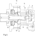
- Fig. 5 shows a hydraulic gerotor or geroler machine 13 comprising such a check valve 1.
- the hydraulic machine 13 comprises a gerotor set 14.
- the gerotor set 14 comprises a star wheel 15 rotating and orbiting within ring gear 16 (when the gerotor set 14 comprises rollers instead of the tips of the teeths of the ring gear 16, it is referred to as "geroler").
- a dog bone 17 transfers the rotating movement to a working section, which in the present embodiment comprises a brake 18.
- the hydraulic machine 14 comprises a valve plate 19 on one side of the gerotor set 14 and a wear plate 20 on the opposite side of the gerotor set 14.
- the machine 13 comprises not only one check valve 1 (as shown), but two check valves opening in opposite flow directions. The other check valve would only be visible at another cross-sectional view.
- Such a hydraulic gerotor or geroler motor is often used in construction equipment, like excavators.
- Such a check valve 1 in hydraulic motors is used for different functions.
- One function of the check valve 1 is to prevent cavitation which may occur during pumping operation of the hydraulic motor due to inertial loading of the machine or application.
- the check valve 1 is used to connect case flow line to one of the directional ports, so as to direct the drain line to the other directional port during pumping operation of the hydraulic motor.
- valve plate 19 which is part of a machine housing of the hydraulic gerotor or geroler machine 13 forms the first part 9 of the valve housing, while the second part 10 of the valve housing is fixed to the valve plate 19.
- the valve plate 19 forms the second part 10 of the valve housing.
- Fig. 1 shows the check valve 1 in an assembly condition, in which the valve chamber 4 opens upwardly in direction of gravity.
- the valve element 7 can be inserted into the valve chamber 4 before fixing the second housing part 10 to the first housing part 9.
- Each array of holes 12 comprises holes 12 arranged around a main flow hole and are connected to the second port 3.
- the second port 3 of one check valve is connected to one directional port and the second port 3 of the other check valve is connected to the other directional port.
- valve element 7 at the port plate 19 When, for example, one directional port is pressurized, the valve element 7 at the port plate 19 will close one passage of case flow with the passage of this directional port while the valve element of the other check valve will open and connect the drain line/case flow with the other directional port during pumping mode of the hydraulic machine.
Landscapes
- Engineering & Computer Science (AREA)
- General Engineering & Computer Science (AREA)
- Mechanical Engineering (AREA)
- Physics & Mathematics (AREA)
- Fluid Mechanics (AREA)
- Check Valves (AREA)
Abstract
Description
- The present invention relates to a check valve comprising a valve housing having a first port and a second port connected to a valve chamber, a valve seat having a valve seat axis and being arranged between the first port and the valve chamber, and a valve element movably arranged within the valve chamber between the valve seat and a stop face opposite the valve seat, wherein the housing comprises a first part having the first port and a second part having the second port and being connected to the first part.
- Furthermore, the invention relates to a hydraulic gerotor or geroler machine comprising such a check valve.
- Such a check valve is known, for example, from
JP 2012-52636 A - A check valve is used to allow a flow of a fluid in one direction and to block the flow of the fluid in the opposite direction, at least when there is a pressure gradient across the check valve. Current designs of check valves, in particular for hydraulic motors, especially gerotor/geroler motors, use many components or complicated structures, which increases the package size and add to costs. It usually increases also external leakage points.
- The object underlying the invention is to have a simple check valve design.
- This object is solved with a check valve described at the outset in that the second port opens into the stop face by means of an array of holes, wherein a cross section area of the holes is smaller than the smallest cross section area of the valve element.
- In such a check valve basically only three parts are necessary, namely the two parts of the valve housing and the valve element. The array of holes allow a flow of the fluid when the check valve is open. The valve element is stopped at the stop surface, however, it cannot close all of the holes of the array, so that a flow is still possible.
- In an embodiment of the invention the area of the array is larger than the largest cross section of the valve element. Thus, a sufficient flow area is permanently available, so that a pressure drop in the check valve can be kept low in an open condition of the check valve.
- In an embodiment of the invention the valve element is moveable perpendicular to the valve seat axis. In other words, the valve element is not guided within the valve chamber, but is free to move in the valve chamber.
- In an embodiment of the invention the stop face is a plane face. This simplifies the machining of the second part.
- In an embodiment of the invention the stop face is in form of a bowl. This simplifies assembly of the check valve, when in a mounting position the stop face is arranged at the lowest position in direction of gravity. The valve element can simply be positioned on the stop face and the first housing part can be mounted to the second housing part from the top. The form of the bowl differs from the form of the valve element, so that the valve element cannot close all of the holes at the same time.
- In an embodiment of the invention the stop face is part of an end face of the second part. The end face of the second part is the face which contacts the first part of the valve housing. This simplifies further the design of the check valve.
- In an embodiment of the invention the holes cover at least 60% of the stop face. The stop face is as large as the cross section of the valve chamber. Basically, the area can cover the whole cross section of the valve chamber. However, in most cases it is sufficient when the holes cover at least 60% of the stop face.
- In an embodiment of the invention at least some of the holes are arranged on a circle. This again allows for a flow of fluid out of the second port independently of the exact position of the valve element. A main flow bore can be arranged at the centre of the circle. In an open condition, this main flow bore might be closed or at least partly closed by the valve element. However, at least some of the remaining holes of the array remain open.
- In an embodiment of the invention the circle has a centre that coincides with the valve seat access. Accordingly, symmetric conditions can be achieved which is positive for the flow of the fluid through the check valve.
- In an embodiment of the invention the array covers an area which is larger than a cross section of the second port. Thus, enough area is available for the array of holes.
- In an embodiment of the invention the valve element is in form of a ball. The ball can be used, on the one hand, to close the check valve when it seats against the valve seat. On the other hand, when it rests against the stop face, there is always a space available through which the flow of fluid can escape to the second port.
- In an embodiment of the invention a sealing is arranged between the first housing part and the second housing part. Such a sealing keeps the risk of a leakage low.
- The invention furthermore relates to a hydraulic gerotor or geroler machine comprising such a check valve.
- A hydraulic gerotor or geroler machine is an orbiting machine which is preferably used as a hydraulic motor for different functions. One function of a check valve is to prevent cavitation which may occur during pumping operation of the hydraulic motor due to inertial loading of the machine/application. Generally, in a gerotor or geroler motor which is used for swing application of an excavator, the check valve is used to connect case flow line to one of the directional ports so as to direct the drain line/case flow to the respective directional ports during pumping operation of the hydraulic motor.
- In an embodiment of the invention the machine comprises a machine housing, wherein a part of the machine housing forms a part of the valve housing. This simplifies the construction of the hydraulic machine.
- In an embodiment of the invention the part of the machine housing forms the first part of the valve housing. Thus, fluid is blocked from entering the hydraulic machine in this case. However, in many cases, such a hydraulic machine will comprise two such check valves, which open in opposite directions. In this case the machine housing forms the second part of the valve housing of the second check valve.
- Preferred embodiments of the invention will now be described with reference to the drawings, wherein:
-
Fig. 1 shows a schematic illustration of a check valve in a mounting position, -
Fig. 2 shows a schematic perspective view of the check valve, -
Fig. 3 shows a schematic view of the check valve in closed condition, -
Fig. 4 shows a schematic view of the check valve in open condition and -
Fig. 5 shows a schematic cross-sectional view of a hydraulic gerotor or geroler machine comprising such a check valve. -
Figure 1 shows acheck valve 1 comprising valve housing having afirst port 2 and asecond port 3. Bothports valve chamber 4. Thefirst port 2 opens into thevalve chamber 4 by means of avalve seat 5. Thevalve seat 5 comprises avalve seat axis 6. - A
valve element 7 is arranged in thevalve chamber 4. Thevalve element 7 is in form of a ball. Thevalve element 7 is moveably arranged within thevalve chamber 4 between thevalve seat 5 and astop face 8 opposite thevalve seat 5. - The valve housing comprises a
first part 9 having thefirst port 2 and asecond part 10 having thesecond port 3. Thesecond part 10 is connected to thefirst part 9. Sealing means 11, for example an O-ring, are arranged between thefirst part 9 and thesecond part 10. - The
second port 3 opens into thestop face 8 by means of an array ofholes 12. The cross section of theholes 12 is smaller than the smallest cross section area of thevalve element 7. In the embodiment described thevalve element 7 is in form of a ball, so that the diameter of the ball defines the cross-section area of the valve element. Theholes 12 can be in form of cylinder bores having a diameter which is smaller than the diameter of the ball shapedvalve element 7. - The
stop face 8 is a plane face. Thus, when thevalve element 7 rests against thestop face 8, there is always a number ofholes 12 open to allow a fluid to escape out of thevalve chamber 4 to thesecond port 3. - In another embodiment the
stop face 8 is in form of a bowl. The bowl can be rather flat. The form of the bowl serves to facilitate assembly of the check-valve, when thestop face 8 is arranged below thevalve element 7. In the case thevalve element 7 is simply positioned in the bowl and thefirst part 9 can be mounted to thesecond part 10 without the risk that thevalve element 7 gets lost during assembly. - As can be seen in
figures 1 to 4 , the diameter of thevalve chamber 4 is much larger than the diameter of thevalve element 7. Accordingly, thevalve element 7 is not only moveable between thevalve seat 5 and thestop face 8, but it can also move perpendicular to thevalve seat axis 6. In other words, thevalve element 7 is not guided in thevalve chamber 4. - In the present embodiment, the
stop face 8 is an end face of thesecond part 10. This means that thestop face 8 forms a part of the end face of thesecond part 10. This end face contacts thefirst part 9, when the twoparts stop face 8, for example by drilling. - The
holes 12 cover at least 60% of the stop face. This takes into account, that a circular hole leaves material around it. Even when the whole cross section of thevalve chamber 4 would be covered byholes 12, there would be not all of the cross section available for a fluid flow. - At least some of the
holes 12 are arranged on a circle, as can be seen infigure 2 . The circle has a centre that coincides with the valve seat access. Thus, thecheck valve 1 has a rotational symmetry. A main flow hole (not shown) can be arranged at the centre. - The array in which the
holes 12 are arranged covers an area which is larger than a cross section of thesecond port 3. However, theholes 12 at least partly overlap the cross section of theport 3. This again makes sure that there is always a way for the fluid to flow through thecheck valve 1, when thecheck valve 1 is open. -
Fig. 3 shows thecheck valve 1 in a closed condition. When the flow of fluid is directed from thesecond port 3 to thefirst port 2 thevalve element 7 is dragged to thevalve seat 5 and closes thecheck valve 1. -
Fig. 4 shows thecheck valve 1 in open condition. In this condition the flow is directed from thefirst port 2 to thesecond port 3 and thevalve element 7 is lifted of thevalve seat 5 and brought into a contact with thestop face 8. However, as can be seen infigure 4 , there is always at least onehole 12 open which is connected to thesecond port 3, so that fluid can flow out of thevalve chamber 4. -
Fig. 5 shows a hydraulic gerotor orgeroler machine 13 comprising such acheck valve 1. Thehydraulic machine 13 comprises agerotor set 14. The gerotor set 14 comprises astar wheel 15 rotating and orbiting within ring gear 16 (when the gerotor set 14 comprises rollers instead of the tips of the teeths of thering gear 16, it is referred to as "geroler"). Adog bone 17 transfers the rotating movement to a working section, which in the present embodiment comprises abrake 18. - The
hydraulic machine 14 comprises avalve plate 19 on one side of the gerotor set 14 and awear plate 20 on the opposite side of the gerotor set 14. - It should be mentioned, that the
machine 13 comprises not only one check valve 1 (as shown), but two check valves opening in opposite flow directions. The other check valve would only be visible at another cross-sectional view. - Such a hydraulic gerotor or geroler motor is often used in construction equipment, like excavators. Such a
check valve 1 in hydraulic motors is used for different functions. One function of thecheck valve 1 is to prevent cavitation which may occur during pumping operation of the hydraulic motor due to inertial loading of the machine or application. - When a gerotor or geroler motor is used for swing application of the excavator the
check valve 1 is used to connect case flow line to one of the directional ports, so as to direct the drain line to the other directional port during pumping operation of the hydraulic motor. - In the
check valve 1 shown infigure 5 thevalve plate 19 which is part of a machine housing of the hydraulic gerotor orgeroler machine 13 forms thefirst part 9 of the valve housing, while thesecond part 10 of the valve housing is fixed to thevalve plate 19. For the other check valve (not shown) it is just the other way round, so that thevalve plate 19 forms thesecond part 10 of the valve housing. -
Fig. 1 shows thecheck valve 1 in an assembly condition, in which thevalve chamber 4 opens upwardly in direction of gravity. Thus, thevalve element 7 can be inserted into thevalve chamber 4 before fixing thesecond housing part 10 to thefirst housing part 9. - Each array of
holes 12 comprisesholes 12 arranged around a main flow hole and are connected to thesecond port 3. Thesecond port 3 of one check valve is connected to one directional port and thesecond port 3 of the other check valve is connected to the other directional port. - When, for example, one directional port is pressurized, the
valve element 7 at theport plate 19 will close one passage of case flow with the passage of this directional port while the valve element of the other check valve will open and connect the drain line/case flow with the other directional port during pumping mode of the hydraulic machine.
Claims (15)
- Check valve (1) comprising a valve housing having a first port (2) and a second port (3) connected to a valve chamber (4), a valve seat (5) having a valve seat axis (6) and being arranged between the first port (2) and the valve chamber (4), and a valve element (7) movably arranged within the valve chamber (4) between the valve seat (5) and a stop face (8) opposite the valve seat (5), wherein the valve housing comprises a first part (9) having the first port (2) and a second part (10) having the second port (3) and being connected to the first part (9), characterized in that the second port (3) opens into the stop face (8) by means of an array of holes (12), wherein the cross section area of the holes (12) is smaller than the smallest cross section area of the valve element (7).
- Check valve according to claim 1, characterized in that the area of the array is larger than the largest cross section of the valve element (7).
- Check valve according to claim 1 or 2, characterized in that the valve element (7) is movable perpendicular to the valve seat axis (6).
- Check valve according to any of claims 1 to 3, characterized in that the stop face (8) is a plane face.
- Check valve according to any of claims 1 to 3, characterized in that the stop face (8) is in form of a bowl.
- Check valve according to any of claims 1 to 5, characterized in that the stop face (8) is part of an end face of the second part (10).
- Check valve according to any of claims 1 to 6, characterized in that the holes (12) cover at least 60% of the stop face (8).
- Check valve according to any of claims 1 to 7, characterized in that at least some of the holes (12) are arranged on a circle.
- Check valve according to claim 8, characterized in that the circle has a center that coincides with the valve seat axis (6).
- Check valve according to any of claims 1 to 9, characterized in that the array covers an area which is larger than a cross section of the second port (3).
- Check valve according to any of claims 1 to 10, characterized in that the valve element (7) is in form of a ball.
- Check valve according to any of claims 1 to 11, characterized in that a sealing (11) is arranged between the first part (9) and the second part (10).
- Hydraulic Gerotor or Geroler machine (13) comprising a check valve (1) according to any of claims 1 to 12.
- Hydraulic Gerotor or Geroler machine according to claim 13, characterized in that the machine comprises a machine housing, wherein a part (19) of the machine housing forms a part of the valve housing.
- Hydraulic Gerotor or Geroler machine according to claim 14, characterized in that the part (19) of the machine housing forms the first part (9) of the valve housing.
Priority Applications (3)
| Application Number | Priority Date | Filing Date | Title |
|---|---|---|---|
| EP22205007.2A EP4365451B1 (en) | 2022-11-02 | 2022-11-02 | Check valve and hydraulic gerotor or geroler machine |
| CN202311283840.9A CN117989360A (en) | 2022-11-02 | 2023-09-28 | Check valve and hydraulic gerotor pump machine |
| US18/499,135 US20240142009A1 (en) | 2022-11-02 | 2023-10-31 | Check valve and hydraulic gerotor or geroler machine |
Applications Claiming Priority (1)
| Application Number | Priority Date | Filing Date | Title |
|---|---|---|---|
| EP22205007.2A EP4365451B1 (en) | 2022-11-02 | 2022-11-02 | Check valve and hydraulic gerotor or geroler machine |
Publications (2)
| Publication Number | Publication Date |
|---|---|
| EP4365451A1 true EP4365451A1 (en) | 2024-05-08 |
| EP4365451B1 EP4365451B1 (en) | 2024-09-25 |
Family
ID=84329782
Family Applications (1)
| Application Number | Title | Priority Date | Filing Date |
|---|---|---|---|
| EP22205007.2A Active EP4365451B1 (en) | 2022-11-02 | 2022-11-02 | Check valve and hydraulic gerotor or geroler machine |
Country Status (3)
| Country | Link |
|---|---|
| US (1) | US20240142009A1 (en) |
| EP (1) | EP4365451B1 (en) |
| CN (1) | CN117989360A (en) |
Citations (9)
| Publication number | Priority date | Publication date | Assignee | Title |
|---|---|---|---|---|
| US4976594A (en) * | 1989-07-14 | 1990-12-11 | Eaton Corporation | Gerotor motor and improved pressure balancing therefor |
| JP2006200429A (en) * | 2005-01-20 | 2006-08-03 | Iwaki Co Ltd | Bellows pump |
| EP1947342A1 (en) * | 2007-01-19 | 2008-07-23 | Anest Iwata Corporation | Check valve for a compressor |
| JP2012052636A (en) | 2010-09-03 | 2012-03-15 | Honda Motor Co Ltd | Check valve |
| US20140105775A1 (en) * | 2012-10-12 | 2014-04-17 | White Drive Products, Inc. | Gerotor motor balancing plate structure |
| US20140334957A1 (en) * | 2013-05-10 | 2014-11-13 | John M. Simmons | Pneumatic reciprocating fluid pump with improved check valve assembly, and related methods |
| CN109538795A (en) * | 2018-08-24 | 2019-03-29 | 严勇 | A kind of float type check valve |
| CN209818800U (en) * | 2019-04-29 | 2019-12-20 | 湖北维斯曼新能源科技有限公司 | Novel four-channel check valve |
| WO2021089645A1 (en) * | 2019-11-07 | 2021-05-14 | Parker Hannifin Emea S.À.R.L. | A one-way valve |
Family Cites Families (15)
| Publication number | Priority date | Publication date | Assignee | Title |
|---|---|---|---|---|
| US1490848A (en) * | 1923-01-24 | 1924-04-15 | George A Pettit | Filler neck for locomotive rod cups |
| US2085360A (en) * | 1935-07-09 | 1937-06-29 | Axelson Mfg Company | Pump valve construction |
| US4018247A (en) * | 1975-02-28 | 1977-04-19 | Carr Clifford H | Springless ball valve for high speed compressors |
| US3970106A (en) * | 1975-03-03 | 1976-07-20 | Reed Tool Company | Collapsible ball valve |
| US4229149A (en) * | 1978-08-28 | 1980-10-21 | Turner Richard L | Oil well pump |
| US4655247A (en) * | 1986-01-17 | 1987-04-07 | Chromalloy American Corporation | Ball-type check valve assembly |
| US4945947A (en) * | 1989-05-26 | 1990-08-07 | Chromalloy American Corporation | Ball-type check valve |
| US5012867A (en) * | 1990-04-16 | 1991-05-07 | Otis Engineering Corporation | Well flow control system |
| US5507312A (en) * | 1994-03-08 | 1996-04-16 | Dillman; Charles M. | Ball check valve |
| US5624248A (en) * | 1996-02-21 | 1997-04-29 | Eaton Corporation | Gerotor motor and improved balancing plate seal therefor |
| DE19928224A1 (en) * | 1999-06-19 | 2000-12-21 | Vorwerk Co Interholding | Vacuum cleaner fitting with suction channel has valve opened by flow deflection caused by reduction in inlet cross-section of valve chamber caused by inserting component to be monitored |
| JP6473473B2 (en) * | 2017-03-27 | 2019-02-20 | 本田技研工業株式会社 | Valve structure and hydraulic circuit using the same |
| DE102017219004A1 (en) * | 2017-10-24 | 2019-04-25 | Brose Fahrzeugteile GmbH & Co. Kommanditgesellschaft, Würzburg | Electromotive oil pump with check valve |
| US10669679B2 (en) * | 2018-02-26 | 2020-06-02 | Graco Minnesota Inc. | Ground striper pump piston having dual checks |
| US10914148B2 (en) * | 2018-11-05 | 2021-02-09 | Jerry Rich | Hydraulic ball guide for subsurface ball valves |
-
2022
- 2022-11-02 EP EP22205007.2A patent/EP4365451B1/en active Active
-
2023
- 2023-09-28 CN CN202311283840.9A patent/CN117989360A/en active Pending
- 2023-10-31 US US18/499,135 patent/US20240142009A1/en active Pending
Patent Citations (9)
| Publication number | Priority date | Publication date | Assignee | Title |
|---|---|---|---|---|
| US4976594A (en) * | 1989-07-14 | 1990-12-11 | Eaton Corporation | Gerotor motor and improved pressure balancing therefor |
| JP2006200429A (en) * | 2005-01-20 | 2006-08-03 | Iwaki Co Ltd | Bellows pump |
| EP1947342A1 (en) * | 2007-01-19 | 2008-07-23 | Anest Iwata Corporation | Check valve for a compressor |
| JP2012052636A (en) | 2010-09-03 | 2012-03-15 | Honda Motor Co Ltd | Check valve |
| US20140105775A1 (en) * | 2012-10-12 | 2014-04-17 | White Drive Products, Inc. | Gerotor motor balancing plate structure |
| US20140334957A1 (en) * | 2013-05-10 | 2014-11-13 | John M. Simmons | Pneumatic reciprocating fluid pump with improved check valve assembly, and related methods |
| CN109538795A (en) * | 2018-08-24 | 2019-03-29 | 严勇 | A kind of float type check valve |
| CN209818800U (en) * | 2019-04-29 | 2019-12-20 | 湖北维斯曼新能源科技有限公司 | Novel four-channel check valve |
| WO2021089645A1 (en) * | 2019-11-07 | 2021-05-14 | Parker Hannifin Emea S.À.R.L. | A one-way valve |
Also Published As
| Publication number | Publication date |
|---|---|
| CN117989360A (en) | 2024-05-07 |
| EP4365451B1 (en) | 2024-09-25 |
| US20240142009A1 (en) | 2024-05-02 |
Similar Documents
| Publication | Publication Date | Title |
|---|---|---|
| US9482365B2 (en) | Rotary valve | |
| KR20120039050A (en) | Proportional poppet valve with integral check valve | |
| US4624445A (en) | Lockout valve | |
| US5752426A (en) | Pilot pressure operated directional control valve and an operating cylinder control apparatus | |
| KR20110093670A (en) | Hydraulic control valve for construction machinery | |
| WO2003040574A1 (en) | Multiple hydraulic valve assembly with a monolithic block | |
| KR20120121887A (en) | Proportional valve assembly | |
| EP4365451B1 (en) | Check valve and hydraulic gerotor or geroler machine | |
| JPS62261703A (en) | Safety valve gear | |
| US20200277754A1 (en) | Swing-back preventing apparatus | |
| US9915371B2 (en) | Hydraulic port safety locking device | |
| JP3923956B2 (en) | Rotary switching valve for hydraulic equipment | |
| CN212225655U (en) | Hydraulic flow control valve, hydraulic control system and engineering machinery | |
| JPS5912401Y2 (en) | Small hydraulic power supply device | |
| EP0842803B1 (en) | Hydraulic actuating device for a cover of a vehicle | |
| AU2021216366B2 (en) | Ball for a valve assembly | |
| JP2025020614A (en) | Valve mechanism | |
| KR20240044222A (en) | Hydraulic system with logic valve installed | |
| EP4379244A1 (en) | Flow rate control valve | |
| AU2020335999B2 (en) | Fluid distribution assembly | |
| US20170002936A1 (en) | Valve having spool assembly with insert divider | |
| EP0299928B1 (en) | A priority flow control valve for hydraulic power circuits | |
| JPH01110887A (en) | Closed center fluid device | |
| US4184513A (en) | Multiple three and/or two way valve | |
| JPH0835501A (en) | Multiple directional valve device |
Legal Events
| Date | Code | Title | Description |
|---|---|---|---|
| STAA | Information on the status of an ep patent application or granted ep patent |
Free format text: STATUS: EXAMINATION IS IN PROGRESS |
|
| PUAI | Public reference made under article 153(3) epc to a published international application that has entered the european phase |
Free format text: ORIGINAL CODE: 0009012 |
|
| 17P | Request for examination filed |
Effective date: 20230713 |
|
| AK | Designated contracting states |
Kind code of ref document: A1 Designated state(s): AL AT BE BG CH CY CZ DE DK EE ES FI FR GB GR HR HU IE IS IT LI LT LU LV MC ME MK MT NL NO PL PT RO RS SE SI SK SM TR |
|
| GRAP | Despatch of communication of intention to grant a patent |
Free format text: ORIGINAL CODE: EPIDOSNIGR1 |
|
| STAA | Information on the status of an ep patent application or granted ep patent |
Free format text: STATUS: GRANT OF PATENT IS INTENDED |
|
| INTG | Intention to grant announced |
Effective date: 20240607 |
|
| RBV | Designated contracting states (corrected) |
Designated state(s): AL AT BE BG CH CY CZ DE DK EE ES FI FR GB GR HR HU IE IS IT LI LT LU LV MC ME MK MT NL NO PL PT RO RS SE SI SK SM TR |
|
| P01 | Opt-out of the competence of the unified patent court (upc) registered |
Free format text: CASE NUMBER: APP_37096/2024 Effective date: 20240620 |
|
| GRAS | Grant fee paid |
Free format text: ORIGINAL CODE: EPIDOSNIGR3 |
|
| GRAA | (expected) grant |
Free format text: ORIGINAL CODE: 0009210 |
|
| STAA | Information on the status of an ep patent application or granted ep patent |
Free format text: STATUS: THE PATENT HAS BEEN GRANTED |
|
| AK | Designated contracting states |
Kind code of ref document: B1 Designated state(s): AL AT BE BG CH CY CZ DE DK EE ES FI FR GB GR HR HU IE IS IT LI LT LU LV MC ME MK MT NL NO PL PT RO RS SE SI SK SM TR |
|
| REG | Reference to a national code |
Ref country code: GB Ref legal event code: FG4D |
|
| REG | Reference to a national code |
Ref country code: CH Ref legal event code: EP |
|
| REG | Reference to a national code |
Ref country code: DE Ref legal event code: R096 Ref document number: 602022006364 Country of ref document: DE |
|
| REG | Reference to a national code |
Ref country code: IE Ref legal event code: FG4D |
|
| REG | Reference to a national code |
Ref country code: LT Ref legal event code: MG9D |
|
| PG25 | Lapsed in a contracting state [announced via postgrant information from national office to epo] |
Ref country code: NO Free format text: LAPSE BECAUSE OF FAILURE TO SUBMIT A TRANSLATION OF THE DESCRIPTION OR TO PAY THE FEE WITHIN THE PRESCRIBED TIME-LIMIT Effective date: 20241225 |
|
| PG25 | Lapsed in a contracting state [announced via postgrant information from national office to epo] |
Ref country code: GR Free format text: LAPSE BECAUSE OF FAILURE TO SUBMIT A TRANSLATION OF THE DESCRIPTION OR TO PAY THE FEE WITHIN THE PRESCRIBED TIME-LIMIT Effective date: 20241226 Ref country code: FI Free format text: LAPSE BECAUSE OF FAILURE TO SUBMIT A TRANSLATION OF THE DESCRIPTION OR TO PAY THE FEE WITHIN THE PRESCRIBED TIME-LIMIT Effective date: 20240925 |
|
| PG25 | Lapsed in a contracting state [announced via postgrant information from national office to epo] |
Ref country code: BG Free format text: LAPSE BECAUSE OF FAILURE TO SUBMIT A TRANSLATION OF THE DESCRIPTION OR TO PAY THE FEE WITHIN THE PRESCRIBED TIME-LIMIT Effective date: 20240925 |
|
| PG25 | Lapsed in a contracting state [announced via postgrant information from national office to epo] |
Ref country code: LV Free format text: LAPSE BECAUSE OF FAILURE TO SUBMIT A TRANSLATION OF THE DESCRIPTION OR TO PAY THE FEE WITHIN THE PRESCRIBED TIME-LIMIT Effective date: 20240925 |
|
| PG25 | Lapsed in a contracting state [announced via postgrant information from national office to epo] |
Ref country code: RS Free format text: LAPSE BECAUSE OF FAILURE TO SUBMIT A TRANSLATION OF THE DESCRIPTION OR TO PAY THE FEE WITHIN THE PRESCRIBED TIME-LIMIT Effective date: 20241225 |
|
| REG | Reference to a national code |
Ref country code: NL Ref legal event code: MP Effective date: 20240925 |
|
| PG25 | Lapsed in a contracting state [announced via postgrant information from national office to epo] |
Ref country code: RS Free format text: LAPSE BECAUSE OF FAILURE TO SUBMIT A TRANSLATION OF THE DESCRIPTION OR TO PAY THE FEE WITHIN THE PRESCRIBED TIME-LIMIT Effective date: 20241225 Ref country code: NO Free format text: LAPSE BECAUSE OF FAILURE TO SUBMIT A TRANSLATION OF THE DESCRIPTION OR TO PAY THE FEE WITHIN THE PRESCRIBED TIME-LIMIT Effective date: 20241225 Ref country code: LV Free format text: LAPSE BECAUSE OF FAILURE TO SUBMIT A TRANSLATION OF THE DESCRIPTION OR TO PAY THE FEE WITHIN THE PRESCRIBED TIME-LIMIT Effective date: 20240925 Ref country code: GR Free format text: LAPSE BECAUSE OF FAILURE TO SUBMIT A TRANSLATION OF THE DESCRIPTION OR TO PAY THE FEE WITHIN THE PRESCRIBED TIME-LIMIT Effective date: 20241226 Ref country code: FI Free format text: LAPSE BECAUSE OF FAILURE TO SUBMIT A TRANSLATION OF THE DESCRIPTION OR TO PAY THE FEE WITHIN THE PRESCRIBED TIME-LIMIT Effective date: 20240925 Ref country code: BG Free format text: LAPSE BECAUSE OF FAILURE TO SUBMIT A TRANSLATION OF THE DESCRIPTION OR TO PAY THE FEE WITHIN THE PRESCRIBED TIME-LIMIT Effective date: 20240925 |
|
| REG | Reference to a national code |
Ref country code: AT Ref legal event code: MK05 Ref document number: 1726831 Country of ref document: AT Kind code of ref document: T Effective date: 20240925 |
|
| PG25 | Lapsed in a contracting state [announced via postgrant information from national office to epo] |
Ref country code: NL Free format text: LAPSE BECAUSE OF FAILURE TO SUBMIT A TRANSLATION OF THE DESCRIPTION OR TO PAY THE FEE WITHIN THE PRESCRIBED TIME-LIMIT Effective date: 20240925 |
|
| PG25 | Lapsed in a contracting state [announced via postgrant information from national office to epo] |
Ref country code: IS Free format text: LAPSE BECAUSE OF FAILURE TO SUBMIT A TRANSLATION OF THE DESCRIPTION OR TO PAY THE FEE WITHIN THE PRESCRIBED TIME-LIMIT Effective date: 20250125 Ref country code: PT Free format text: LAPSE BECAUSE OF FAILURE TO SUBMIT A TRANSLATION OF THE DESCRIPTION OR TO PAY THE FEE WITHIN THE PRESCRIBED TIME-LIMIT Effective date: 20250127 |
|
| PG25 | Lapsed in a contracting state [announced via postgrant information from national office to epo] |
Ref country code: RO Free format text: LAPSE BECAUSE OF FAILURE TO SUBMIT A TRANSLATION OF THE DESCRIPTION OR TO PAY THE FEE WITHIN THE PRESCRIBED TIME-LIMIT Effective date: 20240925 Ref country code: SM Free format text: LAPSE BECAUSE OF FAILURE TO SUBMIT A TRANSLATION OF THE DESCRIPTION OR TO PAY THE FEE WITHIN THE PRESCRIBED TIME-LIMIT Effective date: 20240925 |
|
| PG25 | Lapsed in a contracting state [announced via postgrant information from national office to epo] |
Ref country code: ES Free format text: LAPSE BECAUSE OF FAILURE TO SUBMIT A TRANSLATION OF THE DESCRIPTION OR TO PAY THE FEE WITHIN THE PRESCRIBED TIME-LIMIT Effective date: 20240925 |
|
| PG25 | Lapsed in a contracting state [announced via postgrant information from national office to epo] |
Ref country code: EE Free format text: LAPSE BECAUSE OF FAILURE TO SUBMIT A TRANSLATION OF THE DESCRIPTION OR TO PAY THE FEE WITHIN THE PRESCRIBED TIME-LIMIT Effective date: 20240925 Ref country code: AT Free format text: LAPSE BECAUSE OF FAILURE TO SUBMIT A TRANSLATION OF THE DESCRIPTION OR TO PAY THE FEE WITHIN THE PRESCRIBED TIME-LIMIT Effective date: 20240925 |
|
| PG25 | Lapsed in a contracting state [announced via postgrant information from national office to epo] |
Ref country code: CZ Free format text: LAPSE BECAUSE OF FAILURE TO SUBMIT A TRANSLATION OF THE DESCRIPTION OR TO PAY THE FEE WITHIN THE PRESCRIBED TIME-LIMIT Effective date: 20240925 Ref country code: PL Free format text: LAPSE BECAUSE OF FAILURE TO SUBMIT A TRANSLATION OF THE DESCRIPTION OR TO PAY THE FEE WITHIN THE PRESCRIBED TIME-LIMIT Effective date: 20240925 |
|
| PG25 | Lapsed in a contracting state [announced via postgrant information from national office to epo] |
Ref country code: IT Free format text: LAPSE BECAUSE OF FAILURE TO SUBMIT A TRANSLATION OF THE DESCRIPTION OR TO PAY THE FEE WITHIN THE PRESCRIBED TIME-LIMIT Effective date: 20240925 Ref country code: SK Free format text: LAPSE BECAUSE OF FAILURE TO SUBMIT A TRANSLATION OF THE DESCRIPTION OR TO PAY THE FEE WITHIN THE PRESCRIBED TIME-LIMIT Effective date: 20240925 |
|
| REG | Reference to a national code |
Ref country code: DE Ref legal event code: R097 Ref document number: 602022006364 Country of ref document: DE |
|
| PG25 | Lapsed in a contracting state [announced via postgrant information from national office to epo] |
Ref country code: MC Free format text: LAPSE BECAUSE OF FAILURE TO SUBMIT A TRANSLATION OF THE DESCRIPTION OR TO PAY THE FEE WITHIN THE PRESCRIBED TIME-LIMIT Effective date: 20240925 |
|
| PG25 | Lapsed in a contracting state [announced via postgrant information from national office to epo] |
Ref country code: DK Free format text: LAPSE BECAUSE OF FAILURE TO SUBMIT A TRANSLATION OF THE DESCRIPTION OR TO PAY THE FEE WITHIN THE PRESCRIBED TIME-LIMIT Effective date: 20240925 |
|
| PG25 | Lapsed in a contracting state [announced via postgrant information from national office to epo] |
Ref country code: LU Free format text: LAPSE BECAUSE OF NON-PAYMENT OF DUE FEES Effective date: 20241102 |
|
| PLBE | No opposition filed within time limit |
Free format text: ORIGINAL CODE: 0009261 |
|
| STAA | Information on the status of an ep patent application or granted ep patent |
Free format text: STATUS: NO OPPOSITION FILED WITHIN TIME LIMIT |
|
| REG | Reference to a national code |
Ref country code: BE Ref legal event code: MM Effective date: 20241130 |
|
| 26N | No opposition filed |
Effective date: 20250626 |
|
| PG25 | Lapsed in a contracting state [announced via postgrant information from national office to epo] |
Ref country code: SE Free format text: LAPSE BECAUSE OF FAILURE TO SUBMIT A TRANSLATION OF THE DESCRIPTION OR TO PAY THE FEE WITHIN THE PRESCRIBED TIME-LIMIT Effective date: 20240925 |
|
| PG25 | Lapsed in a contracting state [announced via postgrant information from national office to epo] |
Ref country code: BE Free format text: LAPSE BECAUSE OF NON-PAYMENT OF DUE FEES Effective date: 20241130 |
|
| PG25 | Lapsed in a contracting state [announced via postgrant information from national office to epo] |
Ref country code: FR Free format text: LAPSE BECAUSE OF NON-PAYMENT OF DUE FEES Effective date: 20241125 |
|
| PG25 | Lapsed in a contracting state [announced via postgrant information from national office to epo] |
Ref country code: IE Free format text: LAPSE BECAUSE OF NON-PAYMENT OF DUE FEES Effective date: 20241102 |
|
| PGFP | Annual fee paid to national office [announced via postgrant information from national office to epo] |
Ref country code: DE Payment date: 20251007 Year of fee payment: 4 |
|
| PG25 | Lapsed in a contracting state [announced via postgrant information from national office to epo] |
Ref country code: HR Free format text: LAPSE BECAUSE OF FAILURE TO SUBMIT A TRANSLATION OF THE DESCRIPTION OR TO PAY THE FEE WITHIN THE PRESCRIBED TIME-LIMIT Effective date: 20240925 |
|
| PG25 | Lapsed in a contracting state [announced via postgrant information from national office to epo] |
Ref country code: HU Free format text: LAPSE BECAUSE OF FAILURE TO SUBMIT A TRANSLATION OF THE DESCRIPTION OR TO PAY THE FEE WITHIN THE PRESCRIBED TIME-LIMIT; INVALID AB INITIO Effective date: 20221102 |
|
| PG25 | Lapsed in a contracting state [announced via postgrant information from national office to epo] |
Ref country code: CY Free format text: LAPSE BECAUSE OF FAILURE TO SUBMIT A TRANSLATION OF THE DESCRIPTION OR TO PAY THE FEE WITHIN THE PRESCRIBED TIME-LIMIT; INVALID AB INITIO Effective date: 20221102 |
|
| PG25 | Lapsed in a contracting state [announced via postgrant information from national office to epo] |
Ref country code: TR Free format text: LAPSE BECAUSE OF FAILURE TO SUBMIT A TRANSLATION OF THE DESCRIPTION OR TO PAY THE FEE WITHIN THE PRESCRIBED TIME-LIMIT Effective date: 20240925 |
|
| PG25 | Lapsed in a contracting state [announced via postgrant information from national office to epo] |
Ref country code: SI Free format text: LAPSE BECAUSE OF FAILURE TO SUBMIT A TRANSLATION OF THE DESCRIPTION OR TO PAY THE FEE WITHIN THE PRESCRIBED TIME-LIMIT Effective date: 20240925 |
|
| REG | Reference to a national code |
Ref country code: CH Ref legal event code: H13 Free format text: ST27 STATUS EVENT CODE: U-0-0-H10-H13 (AS PROVIDED BY THE NATIONAL OFFICE) Effective date: 20260623 |
|
| PG25 | Lapsed in a contracting state [announced via postgrant information from national office to epo] |
Ref country code: LT Free format text: LAPSE BECAUSE OF FAILURE TO SUBMIT A TRANSLATION OF THE DESCRIPTION OR TO PAY THE FEE WITHIN THE PRESCRIBED TIME-LIMIT Effective date: 20240925 |
|
| PG25 | Lapsed in a contracting state [announced via postgrant information from national office to epo] |
Ref country code: ME Free format text: LAPSE BECAUSE OF FAILURE TO SUBMIT A TRANSLATION OF THE DESCRIPTION OR TO PAY THE FEE WITHIN THE PRESCRIBED TIME-LIMIT Effective date: 20240925 |
|
| PG25 | Lapsed in a contracting state [announced via postgrant information from national office to epo] |
Ref country code: CH Free format text: LAPSE BECAUSE OF NON-PAYMENT OF DUE FEES Effective date: 20251130 |