EP4365370A1 - Hose clamp structure and work machine - Google Patents
Hose clamp structure and work machine Download PDFInfo
- Publication number
- EP4365370A1 EP4365370A1 EP22832510.6A EP22832510A EP4365370A1 EP 4365370 A1 EP4365370 A1 EP 4365370A1 EP 22832510 A EP22832510 A EP 22832510A EP 4365370 A1 EP4365370 A1 EP 4365370A1
- Authority
- EP
- European Patent Office
- Prior art keywords
- vertical plate
- plate
- clamping member
- opening
- hose
- Prior art date
- Legal status (The legal status is an assumption and is not a legal conclusion. Google has not performed a legal analysis and makes no representation as to the accuracy of the status listed.)
- Pending
Links
Images








Classifications
-
- E—FIXED CONSTRUCTIONS
- E02—HYDRAULIC ENGINEERING; FOUNDATIONS; SOIL SHIFTING
- E02F—DREDGING; SOIL-SHIFTING
- E02F9/00—Component parts of dredgers or soil-shifting machines, not restricted to one of the kinds covered by groups E02F3/00 - E02F7/00
- E02F9/20—Drives; Control devices
- E02F9/22—Hydraulic or pneumatic drives
- E02F9/2264—Arrangements or adaptations of elements for hydraulic drives
- E02F9/2275—Hoses and supports therefor and protection therefor
-
- B—PERFORMING OPERATIONS; TRANSPORTING
- B60—VEHICLES IN GENERAL
- B60R—VEHICLES, VEHICLE FITTINGS, OR VEHICLE PARTS, NOT OTHERWISE PROVIDED FOR
- B60R16/00—Electric or fluid circuits specially adapted for vehicles and not otherwise provided for; Arrangement of elements of electric or fluid circuits specially adapted for vehicles and not otherwise provided for
- B60R16/08—Electric or fluid circuits specially adapted for vehicles and not otherwise provided for; Arrangement of elements of electric or fluid circuits specially adapted for vehicles and not otherwise provided for fluid
-
- E—FIXED CONSTRUCTIONS
- E02—HYDRAULIC ENGINEERING; FOUNDATIONS; SOIL SHIFTING
- E02F—DREDGING; SOIL-SHIFTING
- E02F3/00—Dredgers; Soil-shifting machines
- E02F3/04—Dredgers; Soil-shifting machines mechanically-driven
- E02F3/96—Dredgers; Soil-shifting machines mechanically-driven with arrangements for alternate or simultaneous use of different digging elements
- E02F3/963—Arrangements on backhoes for alternate use of different tools
- E02F3/964—Arrangements on backhoes for alternate use of different tools of several tools mounted on one machine
-
- E—FIXED CONSTRUCTIONS
- E02—HYDRAULIC ENGINEERING; FOUNDATIONS; SOIL SHIFTING
- E02F—DREDGING; SOIL-SHIFTING
- E02F9/00—Component parts of dredgers or soil-shifting machines, not restricted to one of the kinds covered by groups E02F3/00 - E02F7/00
- E02F9/08—Superstructures; Supports for superstructures
- E02F9/0858—Arrangement of component parts installed on superstructures not otherwise provided for, e.g. electric components, fenders, air-conditioning units
- E02F9/0866—Engine compartment, e.g. heat exchangers, exhaust filters, cooling devices, silencers, mufflers, position of hydraulic pumps in the engine compartment
-
- F—MECHANICAL ENGINEERING; LIGHTING; HEATING; WEAPONS; BLASTING
- F16—ENGINEERING ELEMENTS AND UNITS; GENERAL MEASURES FOR PRODUCING AND MAINTAINING EFFECTIVE FUNCTIONING OF MACHINES OR INSTALLATIONS; THERMAL INSULATION IN GENERAL
- F16L—PIPES; JOINTS OR FITTINGS FOR PIPES; SUPPORTS FOR PIPES, CABLES OR PROTECTIVE TUBING; MEANS FOR THERMAL INSULATION IN GENERAL
- F16L5/00—Devices for use where pipes, cables or protective tubing pass through walls or partitions
-
- E—FIXED CONSTRUCTIONS
- E02—HYDRAULIC ENGINEERING; FOUNDATIONS; SOIL SHIFTING
- E02F—DREDGING; SOIL-SHIFTING
- E02F9/00—Component parts of dredgers or soil-shifting machines, not restricted to one of the kinds covered by groups E02F3/00 - E02F7/00
- E02F9/20—Drives; Control devices
- E02F9/22—Hydraulic or pneumatic drives
- E02F9/2278—Hydraulic circuits
- E02F9/2285—Pilot-operated systems
-
- F—MECHANICAL ENGINEERING; LIGHTING; HEATING; WEAPONS; BLASTING
- F16—ENGINEERING ELEMENTS AND UNITS; GENERAL MEASURES FOR PRODUCING AND MAINTAINING EFFECTIVE FUNCTIONING OF MACHINES OR INSTALLATIONS; THERMAL INSULATION IN GENERAL
- F16L—PIPES; JOINTS OR FITTINGS FOR PIPES; SUPPORTS FOR PIPES, CABLES OR PROTECTIVE TUBING; MEANS FOR THERMAL INSULATION IN GENERAL
- F16L5/00—Devices for use where pipes, cables or protective tubing pass through walls or partitions
- F16L5/02—Sealing
- F16L5/14—Sealing for double-walled or multi-channel pipes
Definitions
- the present invention relates to a hose clamp structure and a working machine.
- a hose clamp structure disclosed in PTL 1 is known.
- a cutout recess is formed in an upper portion of a partition plate that partitions the lower front of a prime mover chamber that houses a prime mover such that the cutout recess is recessed downward from an upper end of the partition plate, a grommet that holds a hose in an up-down direction is inserted into the cutout recess, a retaining plate that prevents the grommet from being removed from the cutout recess is attached to the partition plate, and further the grommet and the retaining plate are pressed from above by a seal body provided on a partition wall that separates the prime mover chamber from the upper front of the prime mover chamber.
- the hose clamp structure disclosed in PTL 1 has a problem that the partition wall needs to be removed when the hose is removed, and thus maintainability is poor.
- an object of the present invention is to provide a hose clamp structure and a working machine from which a hose can be easily removed.
- a hose clamp structure includes a vertical plate having an opening, a groove portion provided at a back side of the vertical plate on one of opposite sides of the opening in a plate-surface parallel direction such that the groove portion is adjacent to the opening, the groove portion being open toward the opening in the plate-surface parallel direction, a receiver portion provided at the back side of the vertical plate on the other of the opposite sides of the opening in the plate-surface parallel direction, a first clamping member to be inserted in the groove portion, a second clamping member made of an elastic member and configured such that the second clamping member is placed in the receiver portion through the opening from a front side of the vertical plate to contact the receiver portion with the first clamping member being inserted in the groove portion and such that at least one hose passing through the opening is held between the first clamping member and the second clamping member, and a pressing member to be attached to the vertical plate to press the second clamping member from the front side of the vertical plate to elastically deform the second clamping member to cause the second clamping member to press the
- the first clamping member has a thickness substantially equal to a groove width of the groove portion.
- the second clamping member has a thickness such that the second clamping member protrudes forward through a back surface of the vertical plate via the opening when the second clamping member is in contact with the receiver portion but is not pressed by the pressing member.
- the pressing member includes a main plate to be inserted in the opening to press the second clamping member, and an attachment plate fixed to the main plate to contact a front surface of the vertical plate and attached to the vertical plate.
- the vertical plate has an insertion groove extending from an outer edge of the vertical plate toward the opening to communicate with the opening and configured to allow the at least one hose to pass through the insertion groove in a direction perpendicular to a longitudinal direction of the at least one hose.
- the groove portion includes a first portion which is a portion of the vertical plate that defines one of opposite edges of the opening in the plate-surface parallel direction, a second portion facing the first portion at the back side of the vertical plate, and a third portion extending from one of opposite edges of the second portion in the plate-surface parallel direction toward a back surface of the vertical plate and fixed to the vertical plate.
- the receiver portion includes a first wall portion facing the opening at the back side of the vertical plate, and a second wall portion extending from one of opposite edges of the first wall portion in the plate-surface parallel direction toward a back surface of the vertical plate and fixed to the vertical plate.
- the second clamping member is placed to contact the first wall portion and the second wall portion through the opening from the front side of the vertical plate.
- a working machine includes a machine body, a prime mover on the machine body, a partition wall to separate a prime mover chamber housing the prime mover from an outside of the prime mover chamber, and the hose clamp structure, wherein the vertical plate defines a portion of the partition wall, and the at least one hose is guided from the prime mover chamber to an outside of the partition wall.
- hose(s) can be easily removed by simply removing the pressing member from the vertical plate.
- FIG. 1 is a schematic side view illustrating an overall configuration of a working machine 1 according to the present embodiment.
- a backhoe which is a turning working machine, is exemplified as the working machine 1.
- the working machine 1 includes a machine body (turning base) 2, a traveling device 3, and a working device 4.
- An operator's seat 6 on which an operator (driver) is seated is mounted on the machine body 2.
- a direction toward the front of the operator seated on the operator's seat 6 of the working machine 1 is described as a forward side (machine-body forward side)
- a direction toward the rear of the operator is described as a rearward side (machine-body rearward side)
- an arrow K1 direction in FIG. 1 is described as a front-rear direction (machine-body front-rear direction).
- a direction toward the left of the operator is described as a leftward side
- a direction toward the right of the operator far side in FIG. 1
- a rightward side is described as a rightward side.
- a horizontal direction that is a direction perpendicular to the front-rear direction K1 is described as a machine-body width direction.
- a direction from a center portion to a right portion or a left portion in a width direction of the machine body 2 is described as an outward side in the machine-body width direction. That is, the outward side in the machine-body width direction is a direction away from the center in the width direction of the machine body 2 in the machine-body width direction.
- a direction opposite to the outward side in the machine-body width direction is described as an inward side in the machine-body width direction. That is, the inward side in the machine-body width direction is a direction toward the center in the width direction of the machine body 2 in the machine-body width direction.
- the traveling device 3 is a crawler type traveling device that supports the machine body 2 so as to be travelable, and includes a traveling frame 3A, a first traveling device 3L provided on the left of the traveling frame 3A, and a second traveling device 3R provided on the right of the traveling frame 3A.
- the first traveling device 3L and the second traveling device 3R are driven by a traveling motor M1 including a hydraulic motor (hydraulic actuator).
- the crawler type traveling device 3 is used, but this does not imply any limitation, and a wheel type traveling device or the like may be used.
- a dozer device 7 is attached to a front portion of the traveling device 3.
- the dozer device 7 can be driven by a dozer cylinder including a hydraulic cylinder (hydraulic actuator).
- the machine body 2 is supported on the traveling device 3 via a turning bearing 8 so as to be turnable about a turning axis X1 that is an axis extending in an up-down direction.
- the machine body 2 includes, in a front portion thereof, a support bracket 9 and a swing bracket 10 that support the working device 4.
- the support bracket 9 is provided so as to protrude forward from the machine body 2.
- the swing bracket 10 is attached to a front portion of the support bracket 9 so as to be swingable about a vertical axis (an axis extending in the up-down direction).
- the working device 4 includes a boom 11, an arm 12, and a bucket 13.
- a base portion of the boom 11 is pivotally attached to an upper portion of the swing bracket 10 so as to be rotatable about a lateral axis (an axis extending in the machine-body width direction).
- the arm 12 is pivotally attached to a distal end side of the boom 11 so as to be rotatable about a lateral axis.
- the bucket 13 is provided at a distal end side of the arm 12 so as to be capable of performing shoveling and dumping.
- the shoveling is a motion of swinging the bucket 13 in a direction toward the boom 11, and is, for example, a motion of shoveling earth and sand or the like.
- the dumping is a motion of swinging the bucket 13 in a direction away from the boom 11, and is, for example, a motion of dropping (discharging) shoveled earth and sand or the like.
- another working tool that can be driven by a hydraulic actuator can be attached to the working machine 1.
- the other working tool include a hydraulic breaker, a hydraulic crusher, an angle broom, an earth auger, a pallet fork, a sweeper, a mower, and a snow blower.
- the swing bracket 10 is swingable by expansion and contraction of a swing cylinder (not illustrated).
- the boom 11 is swingable by expansion and contraction of a boom cylinder C2.
- the arm 12 is swingable by expansion and contraction of an arm cylinder C3.
- the bucket 13 is capable of performing shoveling and dumping by expansion and contraction of a bucket cylinder C4.
- the swing cylinder, the boom cylinder C2, the arm cylinder C3, and the bucket cylinder C4 include hydraulic cylinders (hydraulic actuators).
- a prime mover E1 is mounted in a rear portion of the machine body 2.
- the prime mover E1 is a diesel engine.
- the prime mover E1 may be a gasoline engine or an electric motor, or may be a hybrid type including an engine and an electric motor.
- An operation unit 18 including the operator's seat 6, a traveling lever 16 located forward of the operator's seat 6, a manipulating device 17L located leftward of the operator's seat 6, a manipulating device 17R located rightward of the operator's seat 6, and the like is mounted on a forward of the prime mover E1 of the machine body 2.
- the traveling lever 16 is an operation member that operates the traveling device 3.
- the manipulating devices 17L and 17R are devices that perform, for example, a swinging operation of the boom 11, a swinging operation of the arm 12, operations of shoveling and dumping of the bucket 13, a turning operation of the machine body 2, and the like.
- a step 21 that defines a floor surface is provided on an upper surface side of the machine body 2 and a forward side of the operator's seat 6.
- the machine body 2 includes a turning frame 30 serving as a framework.
- the turning frame 30 includes a turning base plate (base plate) 31 that defines a bottom portion of the machine body 2, a reinforcing rib 32 that reinforces the turning base plate 31, the support bracket 9, and a weight 33 (see FIG. 1 ). Additionally, the turning frame 30 includes brackets, stays, and the like for attaching devices, tanks, other components, and the like mounted on the machine body 2.
- the turning base plate 31 is formed of a thick steel plate or the like.
- the brackets, stays, and the like provided on the turning frame 30 are fixed onto the turning base plate 31 by welding or the like.
- the turning base plate 31 is supported on the traveling device 3 via the turning bearing 8 so as to be rotatable about the turning axis X1.
- the reinforcing rib 32 is formed of a plate member and is provided on the turning base plate 31 to extend from a front portion toward a rear portion. Specifically, the reinforcing rib 32 includes a first vertical rib 32R extending rearward from a rear portion of a left portion of the support bracket 9 provided on the front portion of the turning base plate 31, and a second vertical rib 32L extending rearward from a rear portion of a right portion of the support bracket 9.
- a control valve V1 As illustrated in FIG. 2 , a control valve V1, a hydraulic fluid tank 28, a turning motor 20, and the like are attached on the turning base plate 31.
- the control valve V1 is located on a front portion of a left portion of the turning base plate 31.
- the control valve V1 controls the flow rate of a hydraulic fluid to be supplied to the hydraulic actuators provided in the working machine 1 and driven with the hydraulic fluid.
- the control valve V1 is a valve unit in which control valves that control the flow rate of the hydraulic fluid to be supplied to each of the hydraulic actuators provided in the working machine 1 are collected.
- the hydraulic fluid tank 28 is located rearward of the control valve V1.
- the hydraulic fluid tank 28 is a tank that stores the hydraulic fluid.
- the prime mover E1 is mounted on the rear portion of the turning base plate 31.
- a hydraulic pump 25 is attached to a one-side portion (left portion) in the machine-body width direction of the prime mover E1.
- the hydraulic pump 25 is driven by power of the prime mover E1.
- the hydraulic pump 25 sucks the hydraulic fluid in the hydraulic fluid tank 28 and delivers the hydraulic fluid (pressure oil) for driving the hydraulic actuators such as hydraulic motors, hydraulic cylinders, and the like provided in the working machine 1.
- the hydraulic pump 25 delivers a pilot pressure for actuating a hydraulic valve and a hydraulic pressure for a signal.
- a cooling fan 14 is provided on a right portion of the prime mover E1, and a radiator, an oil cooler, a fuel cooler, and the like are located rightward of the cooling fan 14.
- a partition wall 36 that defines a front portion side of a prime mover chamber E2 that houses the prime mover E1 is provided forward of the prime mover E1.
- the partition wall 36 is a member that separates the prime mover chamber E2 from the front of the prime mover chamber E2 (the outside of the prime mover chamber E2).
- the hydraulic fluid tank 28 is located leftward of the partition wall 36. The hydraulic fluid tank 28 is installed on the turning base plate 31.
- the partition wall 36 includes a partition wall main body 37 and a partition plate 38.
- the partition wall main body 37 is a member that separates the prime mover chamber E2 from the upper front of the prime mover chamber E2, and includes an upper wall 37a and a front wall 37b extending downward from a front portion of the upper wall 37a.
- the partition plate 38 is located lower than the partition wall main body 37. Also, the partition plate 38 is located lower than the step 21. That is, the partition plate 38 is a member that partitions the lower front of the prime mover chamber E2.
- the partition plate 38 includes a first partition plate 38A and a second partition plate 38B.
- the first partition plate 38A is erected on the turning base plate 31 such that plate surfaces face in the front-rear direction K1. Also, the first partition plate 38A is located on the turning base plate 31 so as to extend in the machine-body width direction and is fixed to the turning base plate 31 by welding or the like.
- the second partition plate 38B has a lower portion fixed to a back surface of the first partition plate 38A by welding or the like, and a left portion fixed to the turning base plate 31 by welding or the like.
- a lower portion of the partition wall main body 37 (a lower portion of the front wall 37b) is attached to the second partition plate 38B. As illustrated in FIG. 6 , the second partition plate 38B protrudes leftward of the first partition plate 38A.
- a cover member 39 and a hose clamp 43 are provided between the partition wall 36 and the hydraulic fluid tank 28.
- the hose clamp 43 is located lower than the cover member 39.
- the cover member 39 and the hose clamp 43 close a space between the partition wall 36 and the hydraulic fluid tank 28.
- the cover member 39 and the hose clamp 43 define a portion of the partition wall 36.
- the cover member 39 includes a first cover 40, a second cover 41, and a third cover 42.
- the first cover 40 is formed in a rectangular shape having an angular U-shaped cutout groove 40a that opens leftward.
- the cutout groove 40a is for passing a routing member such as a harness obtained by bundling wires, and a space between the cutout groove 40a and the harness is sealed with a grommet.
- the second cover 41 includes a first portion 41a, a second portion 41b, and a third portion (extension portion) 41c.
- the first portion 41a is fixed to a lower end portion and a front surface side of the first cover 40 by welding or the like.
- the second portion 41b is fixed to a left end portion and the front surface side of the first cover 40 by welding or the like to be located lower than the cutout groove 40a.
- the third portion 41c extends downward from a left portion of the first portion 41a.
- the third cover 42 is formed in a rectangular shape having an angular U-shaped cutout groove 42a that opens downward.
- the cutout groove 42a is formed slightly rightward of a center portion in the machine-body width direction of the third cover 42.
- An upper portion of the third cover 42 is fixed to a front surface of the second portion 41b of the second cover 41 by welding or the like.
- the cutout groove 42a is displaced rightward with respect to the third portion 41c of the second cover 41.
- the cutout groove 42a is a groove for avoiding interference between the third cover member 42 and an upper attachment plate 57A of a pressing member 48 (described later).
- the first cover 40 is bolted to the front wall 37b of the partition wall main body 37, and the second cover 41 is bolted to a flange plate 44 fixed to the hydraulic fluid tank 28 by welding or the like so as to protrude outward from the hydraulic fluid tank 28.
- a cutout portion 44a for avoiding interference with a groove portion 50 (described later) is formed in a lower portion of the flange plate 44 (see FIG. 11 ).
- the third cover 42 is bolted to the second partition plate 38B and the flange plate 44 together with a vertical plate 49 (described later).
- the hose clamp 43 holds hoses such as hydraulic hose(s) 45 guided to an area forward of the partition wall 36 from the prime mover E1 (guided to the outside of the prime mover E1).
- the hose clamp 43 is provided between the partition plate 38 and the hydraulic fluid tank 28.
- the hose clamp 43 is located lower than the step 21 (inside the machine body 2) together with the control valve V1.
- the hydraulic hose(s) 45 held by the hose clamp 43 may be a plurality of hydraulic hoses 45. Most of the plurality of hydraulic hoses 45 are hoses that connect the hydraulic pump 25 and the control valve V1. As illustrated in FIG.
- the number of the plurality of hydraulic hoses 45 is seven.
- the seven hydraulic hoses 45 are arranged in the up-down direction, and two upper hydraulic hoses 45a and three lower hydraulic hoses 45a are small-diameter hoses each having a diameter smaller than the diameter of each of two middle hydraulic hoses 45b.
- the hose clamp 43 includes a holding body 46 attached directly or indirectly to a machine body 2, a clamping tool 47 that is held by the holding body 46 and that holds the hydraulic hoses 45, and a pressing member 48 that presses the clamping tool 47.
- the holding body 46 includes a vertical plate 49, a groove portion 50, a receiver portion 51, and a coupling plate 52.
- the vertical plate 49 is located such that plate surfaces face in the front-rear direction K1. That is, the vertical plate 49 is located such that a plate width direction (plate-surface parallel direction) W1 perpendicular to the up-down direction coincides with the machine-body width direction, and a plate thickness direction coincides with the front-rear direction K1.
- the vertical plate 49 has an opening 53 and an insertion groove 54.
- the vertical plate 49 includes a first vertical wall portion 49a that is a portion (left portion) provided on one of opposite sides in the plate width direction W1 (on the left of the opposite sides in the machine-body width direction, on the right in FIG.
- a second vertical wall portion 49b that is a portion (right portion) provided on the other of the opposite sides in the plate width direction W1 (on the right of the opposite sides in the machine-body width direction, on the left in FIG. 8 ) and that is spaced from the first vertical wall portion 49a in the plate width direction W1, an extension wall 49c extending from an upper portion of the second vertical wall portion 49b toward an upper portion of the first vertical wall portion 49a, and a lower portion wall 49d that couples a lower portion of the first vertical wall portion 49a and a lower portion of the second vertical wall portion 49b.
- a space is provided between the extension wall 49c and the upper portion of the first vertical wall portion 49a.
- the opening 53 is defined by the first vertical wall portion 49a, the second vertical wall portion 49b, the extension wall 49c, and the lower portion wall 49d.
- the opening 53 includes a first edge (left edge) 53a that is one of opposite edges in the plate width direction W1, a second edge (right edge) 53b that is the other of opposite edges in the plate width direction W1, an upper edge 53c, and a lower edge 53d.
- the insertion groove 54 is defined between the extension wall 49c and the upper portion of the first vertical wall portion 49a. That is, the insertion groove 54 extends from an upper end of the vertical plate 49 toward the opening 53 to communicate with the opening 53.
- the insertion groove 54 has a groove width W2 that allows the hydraulic hoses 45 held by the hose clamp 43 to pass therethrough in a direction perpendicular to a longitudinal direction of the hydraulic hoses 45.
- the third cover 42 is superposed on an upper portion at an obverse side (front side) of the vertical plate 49, and the vertical plate 49 is bolted to the second partition plate 38B and the flange plate 44 together with the third cover 42.
- the cutout groove 42a of the third cover 42 is located at a position corresponding to the extension wall 49c of the vertical plate 49.
- the third portion 41c of the second cover 41 is inserted into the insertion groove 54. Also, the third portion 41c slightly protrudes from the insertion groove 54 toward the opening 53.
- the vertical plate 49 is provided with a fixing wall 49e extending forward from a lower end of the lower portion wall 49d. As illustrated in FIG. 4 , the fixing wall 49e is bolted onto the turning base plate 31.
- the fixing wall 49e of the vertical plate 49 is bolted to the turning base plate 31, and then the cover member 39 is placed such that the third cover 42 is located on a front surface of the upper portion of the vertical plate 49.
- the first cover 40 is bolted to the front wall 37b
- the second cover 41 is bolted to the flange plate 44
- the third cover 42 and the vertical plate 49 are bolted together to the second partition plate 38B and the flange plate 44.
- any of the first cover 40, the second cover 41, and the third cover 42 may be fixed first.
- the fixing wall 49e of the vertical plate 49 may be bolted to the turning base plate 31 after the third cover 42 and the vertical plate 49 are fastened together.
- the vertical plate 49 is not limited to the above-described configuration, and, for example, the extension wall 49c may be connected to the upper portion of the first vertical wall portion 49a. That is, the insertion groove 54 is not necessarily provided. Also, the first vertical wall portion 49a and the second vertical wall portion 49b are not limited to the configuration in which they extend in the up-down direction, and they may extend in the horizontal direction or an oblique direction. In other words, the vertical plate 49 may be placed such that the plate width direction W1 coincides with the up-down direction or an oblique direction inclined with respect to the up-down direction.
- the groove portion 50 is provided at a back side of the vertical plate 49 (at the same side of the vertical plate 49 as the back surface 49f) at one of opposite portions in the plate width direction W1 of the vertical plate 49 such that the groove portion 50 is adjacent to the opening 53.
- the groove portion 50 includes a first portion 50a, a second portion 50b, and a third portion 50c.
- the first portion 50a is a right portion of the first vertical wall portion 49a of the vertical plate 49.
- the first portion 50a is a portion of the vertical plate 49 that defines one of opposite edges (the first edge 53a) of the opening 53.
- the second portion 50b faces the first portion 50a with a space therebetween at the back side (at the same side of the vertical plate 49 as the back surface 49f) of the first portion 50a (vertical plate 49).
- the third portion 50c extends from one of opposite edges (left edge) of the second portion 50b in the plate width direction W1 toward the back surface 49f of the first portion 50a (vertical plate 49) and is fixed to the first portion 50a (vertical plate 49) by welding or the like.
- the groove portion 50 is open (opened) toward the opening 53 (rightward) in the plate width direction W1.
- the groove portion 50 extends in the up-down direction.
- a first extension wall 50d is provided at an upper end portion of the third portion 50c to extend rightward from the upper end portion.
- the receiver portion 51 is provided at the back side of the vertical plate 49 (at the same side of the vertical plate 49 as the back surface 49f) at the other of the opposite portions in the plate width direction W1 of the vertical plate 49 (at the other of the opposite sides of the opening 53).
- the receiver portion 51 includes a first wall portion 51a and a second wall portion 51b.
- the first wall portion 51a faces the opening 53 at the back side (at the same side of the vertical plate 49 as the back surface 49f) of the vertical plate 49.
- the second wall portion 51b extends from one of opposite edges (right edge) of the first wall portion 51a in the plate width direction W1 toward the back surface 49f of the vertical plate 49 and is fixed to the vertical plate 49 by welding or the like.
- a left surface of the second wall portion 51b is substantially flush with the second edge 53b of the opening 53. Also, the receiver portion 51 extends in the up-down direction.
- a second extension wall 51c is formed at an upper end portion of the second wall portion 51b to extend leftward (toward the first extension wall 50d) from the upper end portion. The first extension wall 50d and the second extension wall 51c are provided with a space therebetween.
- the coupling plate 52 is in a band plate shape that is long in the plate width direction W1 with plate surfaces facing in the up-down direction, and couples a lower end of the third portion 50c and a lower end of the second wall portion 51b.
- the pressing member 48 includes a main plate 56 and at least one attachment plate 57.
- the main plate 56 is formed of a band plate member that is long in the up-down direction and whose plate surfaces face in the front-rear direction K1.
- the main plate 56 is inserted in the opening 53 to press a second clamping member 59 (described later).
- the attachment plate 57 is fixed to the main plate 56 by welding or the like, comes into contact with a front surface of the vertical plate 49, and is attached to the vertical plate 49 by a bolt 61.
- the main plate 56 is formed to have a length in the up-down direction that allows the main plate 56 to be inserted into the opening 53 and that is substantially equal to a dimension in the up-down direction of the opening 53.
- the attachment plate 57 is provided on each of an upper portion and a lower portion of the main plate 56. That is, the attachment plate 57 includes a pair of attachment plates 57.
- An upper attachment plate 57A has a lower portion fixed to a front surface of the main plate 56 by welding or the like, and an upper portion protruding upward from the main plate 56.
- a lower attachment plate 57B has an upper portion fixed to the front surface of the main plate 56 by welding or the like, and a lower portion protruding downward from the main plate 56.
- the clamping tool 47 includes a first clamping member 58 and a second clamping member 59.
- the first clamping member 58 and the second clamping member 59 are made of elastic members such as rubber.
- the clamping tool 47 has seven insertion holes 60 arranged in the up-down direction, through which the seven hydraulic hoses 45 are inserted in the front-rear direction K1.
- the clamping tool 47 is divided into a left first clamping member 58 and a right second clamping member 59 in a form of dividing each insertion hole 60 into two portions on the left and right.
- the hydraulic hoses 45 can be held by the first clamping member 58 and the second clamping member 59 sandwiching the hydraulic hoses 45 so that the hydraulic hoses 45 are inserted through the insertion holes 60.
- a width W3 in the plate width direction W1 of the first clamping member 58 is narrower than a width W4 in the plate width direction W1 of the second clamping member 59.
- a thickness 59a of the second clamping member 59 (a dimension in a direction perpendicular to the plate width direction W1 and the up-down direction) is thicker than a thickness 58a of the first clamping members 58.
- the first clamping member 58 is a member to be inserted in the groove portion 50.
- a length in the up-down direction of the first clamping member 58 is formed as a length extending from the first extension wall 50d to the coupling plate 52.
- the thickness 58a of the first clamping member 58 is a thickness that allows the first clamping member 58 to be inserted into the groove portion 50 and is substantially equal to a groove width 50e of the groove portion 50.
- the first clamping member 58 has a left portion inserted into the groove portion 50, and a right portion protruding from the groove portion 50. Halves of the insertion holes 60 are formed in the portion of the first clamping member 58 protruding from the groove portion 50.
- the second clamping member 59 is placed through the opening 53 from the front side (forward side) of the vertical plate 49 with the first clamping member 58 being inserted in the groove portion 50 to contact a front surface of the first wall portion 51a and the left surface of the second wall portion 51b of the receiver portion 51 (contact the receiver portion 51).
- the thickness 59a of the second clamping member 59 is a dimension larger than a distance H1 from the front surface of the first wall portion 51a to the back surface 49f of the vertical plate 49.
- the second clamping member 59 has a thickness such that the second clamping member 59 protrudes forward through the back surface 49f of the vertical plate 49 via the opening 53 when the second clamping member 59 is not pressed by the pressing member 48.
- Halves of the insertion holes 60 are in the left portion of the first clamping member 58.
- the right portion of the first clamping member 58 is a portion with which the main plate 56 of the pressing member 48 comes into contact.
- the second clamping member 59 is divided into three portions in the up-down direction.
- An upper portion 59b is a portion corresponding to two of the insertion holes 60 on an upper portion side among the seven insertion holes 60
- a middle portion 59c is a portion corresponding to two of the insertion holes 60 in a middle portion among the seven insertion holes 60
- a lower portion 59d is a portion corresponding to three of the insertion holes 60 on a lower portion side among the seven insertion holes 60.
- the hydraulic hoses 45 can be held by mounting the clamping tool 47 and the pressing member 48 to the holding body 46 in a state in which the cover member 39 and the holding body 46 are attached.
- the first clamping member 58 is inserted into the groove portion 50.
- the hydraulic hoses 45 passed through the opening 53 are fitted to portions of the first clamping member 58 where the insertion holes 60 are provided (portions corresponding to halves of the insertion holes 60).
- the second clamping member 59 is placed through the opening 53 from the front side of the vertical plate 49 to contact the receiver portion 51 (the first wall portion 51a and the second wall portion 51b), and the hydraulic hoses 45 are held by the first clamping member 58 and the second clamping member 59.
- the second clamping member 59 protrudes on the front surface side with respect to the back surface 49f of the vertical plate 49 via the opening 53.
- the pressing member 48 is bolted to the vertical plate 49.
- the main plate 56 of the pressing member 48 is inserted in the opening 53, and presses the second clamping member 59 from the front side (the side opposite the receiver portion 51) to elastically deform the second clamping member 59. Since the second clamping member 59 is elastically deformed, the hydraulic hoses 45 and the first clamping member 58 are pressed by the second clamping member 59, and the hydraulic hoses 45 are firmly held by the hose clamp 43.
- the hydraulic hoses 45 are sandwiched and fixed by the first clamping member 58 and the second clamping member 59 by the second clamping member 59 being elastically deformed, it is possible to suppress pulsation of the hydraulic hoses 45 and to improve vibration damping property. Also, since the second clamping member 59 is elastically deformed, it is possible to secure sealing property and to prevent or reduce the entry of hot air from the prime mover chamber E2 into the machine body 2. Also, since the first clamping member 58 and the second clamping member 59 can be easily removed only by removing the pressing member 48, the hydraulic hoses 45 can be easily removed.
- the hose clamp 43 is mounted on the machine body 2 side after the prime mover E1 is mounted to the machine body 2. Specifically, first, before the prime mover E1 is mounted to the machine body 2, the hydraulic hoses 45 are inserted through the opening 53, the hydraulic hoses 45 are sandwiched by the first clamping member 58 and the second clamping member 59, and then the pressing member 48 is attached to hold the hydraulic hoses 45 by the hose clamp 43. Then, the prime mover E1 is lowered onto the turning base plate 31 and installed on the turning base plate 31 while the hose clamp 43 in a state of holding the hydraulic hoses 45 is placed on the prime mover E1.
- the hose clamp 43 is located forward of the installation position, and the partition wall main body 37 and the hydraulic fluid tank 28 are mounted. Then, for example, the fixing wall 49e of the hose clamp 43 to which the hydraulic hoses 45 have been mounted is bolted to the turning base plate 31. Thereafter, the cover member 39 is placed such that the third cover 42 is located on the front surface of the upper portion of the vertical plate 49, the first cover 40 is bolted to the front wall 37b, and the second cover 41 is bolted to the flange plate 44. Thereafter, the third cover 42 and the vertical plate 49 are bolted together to the second partition plate 38B and the flange plate 44.
- the third cover 42 and the vertical plate 49 may be fastened together first, and then the first cover 40 and the second cover 41 may be fixed. Still alternatively, the third cover 42 and the vertical plate 49 may be fastened together, and then the fixing wall 49e of the vertical plate 49 may be bolted to the turning base plate 31.
- the holding of the hydraulic hoses 45 by the hose clamp 43 can be performed in a wide place, and hence workability is good. Also, the hydraulic hoses 45 can be inserted into the opening 53 via the insertion groove 54, and hence the insertion of the hydraulic hoses 45 can be easily performed.
- the hydraulic hoses 45 are inserted through the opening 53 via the insertion groove 54, the hydraulic hoses 45 are sandwiched by the first clamping member 58 and the second clamping member 59, and then the pressing member 48 is attached. Then, the cover member 39 is mounted to fix an upper portion of the holding body 46.
- the fixing wall 49c may be fixed to the turning base plate 31.
- the third cover 42 and the vertical plate 49 may be bolted together to the second partition plate 38B and the flange plate 44, and then the fixing wall 49c may be fixed to the turning base plate 31. Even in this mounting method, the hydraulic hoses 45 can be inserted through the opening 53 via the insertion groove 54, and hence the insertion of the hydraulic hoses 45 can be easily performed.
- a hose clamp structure as has been described includes a vertical plate 49 having an opening 53, a groove portion 50 provided at a back side (on the same side of the vertical plate 49 as its back surface 49f) of the vertical plate 49 on one of opposite sides of the opening 53 in a plate-surface parallel direction (plate width direction W1) such that the groove portion 50 is adjacent to the opening 53, the groove portion 50 being open toward the opening 53 in the plate-surface parallel direction (plate width direction W1), a receiver portion 51 provided at the back side (on the same side of the vertical plate 49 as its back surface 49f) of the vertical plate 49 on the other of the opposite sides of the opening 53 in the plate-surface parallel direction (plate width direction W1), a first clamping member 58 to be inserted in the groove portion 50, a second clamping member 59 made of an elastic member and configured such that the second clamping member 59 is placed in the receiver portion 51 through the opening 53 from a front side of the vertical plate 49 to contact the receiver portion 51 with the first clamping member 58 being inserted in the groove portion
- hose(s) (hydraulic hose(s) 45) can be easily removed by simply removing the pressing member 48 from the vertical plate 49. Also, since the hydraulic hose 45 is fixed by being clamped between the first clamping member 58 and the second clamping member 59 by elastically deforming the second clamping member 59, it is possible to prevent or reduce the pulsation of the hose 45 which is a hydraulic hose and to improve vibration damping properties.
- the first clamping member 58 has a thickness substantially equal to a groove width 50e of the groove portion 50.
- the second clamping member 59 has a thickness such that the second clamping member 59 protrudes forward through a back surface 49f of the vertical plate 49 via the opening 53 when the second clamping member 59 is in contact with the receiver portion 51 but is not pressed by the pressing member 48.
- the pressing member 48 includes a main plate 56 to be inserted in the opening 53 to press the second clamping member 59, and an attachment plate 57 fixed to the main plate 56 to contact a front surface of the vertical plate 49 and attached to the vertical plate 49.
- the first clamping member 58 can be easily mounted.
- the vertical plate 49 has an insertion groove 54 extending from an outer edge of the vertical plate 49 toward the opening 53 to communicate with the opening 53 and configured to allow the at least one hose 45 to pass through the insertion groove 54 in a direction perpendicular to a longitudinal direction of the at least one hose 45.
- the hose 45 can be easily passed through the opening 53 via the insertion groove 54.
- the groove portion 50 includes a first portion 50a which is a portion of the vertical plate 49 that defines one of opposite edges (first edge 53a) of the opening 53 in the plate-surface parallel direction (plate width direction W1), a second portion 50b facing the first portion 50a at the back side (on the same side of the vertical plate 49 as its back surface 49f) of the vertical plate 49, and a third portion 50c extending from one of opposite edges of the second portion 50b in the plate-surface parallel direction (plate width direction W1) toward a back surface 49f of the vertical plate 49 and fixed to the vertical plate 49.
- a portion of the vertical plate 49 functions as a portion of the groove portion 50, and thus it is possible to simplify the structure.
- the receiver portion 51 includes a first wall portion 51a facing the opening 53 at the back side (on the same side of the vertical plate 49 as its back surface 49f) of the vertical plate 49, and a second wall portion 51b extending from one of opposite edges of the first wall portion 51a in the plate-surface parallel direction (plate width direction W1) toward a back surface 49f of the vertical plate 49 and fixed to the vertical plate 49.
- the second clamping member 59 is placed to contact the first wall portion 51a and the second wall portion 51b through the opening 53 from the front side of the vertical plate 49.
- the second clamping member 59 can be properly elastically deformed by being clamped between the pressing member 48 and the first wall portion 51a.
- a working machine 1 includes a machine body 2, a prime mover E1 on the machine body 2, a partition wall 36 to separate a prime mover chamber E2 housing the prime mover E1 from an outside of the prime mover chamber E2, and one of the above-described hose clamp structures, wherein the vertical plate 49 defines a portion of the partition wall 36, and the at least one hose 45 is guided from the prime mover chamber E2 to an outside of the partition wall 36.
Landscapes
- Engineering & Computer Science (AREA)
- General Engineering & Computer Science (AREA)
- Mining & Mineral Resources (AREA)
- Civil Engineering (AREA)
- Structural Engineering (AREA)
- Mechanical Engineering (AREA)
- Component Parts Of Construction Machinery (AREA)
- Supports For Pipes And Cables (AREA)
Abstract
Description
- The present invention relates to a hose clamp structure and a working machine.
- A hose clamp structure disclosed in
PTL 1 is known. - In the hose clamp structure disclosed in
PTL 1, a cutout recess is formed in an upper portion of a partition plate that partitions the lower front of a prime mover chamber that houses a prime mover such that the cutout recess is recessed downward from an upper end of the partition plate, a grommet that holds a hose in an up-down direction is inserted into the cutout recess, a retaining plate that prevents the grommet from being removed from the cutout recess is attached to the partition plate, and further the grommet and the retaining plate are pressed from above by a seal body provided on a partition wall that separates the prime mover chamber from the upper front of the prime mover chamber. - PTL 1:
Japanese Unexamined Patent Application Publication No. 2019-116752 - The hose clamp structure disclosed in
PTL 1 has a problem that the partition wall needs to be removed when the hose is removed, and thus maintainability is poor. - In view of the above-described problem, an object of the present invention is to provide a hose clamp structure and a working machine from which a hose can be easily removed.
- A hose clamp structure according to an aspect of the present invention includes a vertical plate having an opening, a groove portion provided at a back side of the vertical plate on one of opposite sides of the opening in a plate-surface parallel direction such that the groove portion is adjacent to the opening, the groove portion being open toward the opening in the plate-surface parallel direction, a receiver portion provided at the back side of the vertical plate on the other of the opposite sides of the opening in the plate-surface parallel direction, a first clamping member to be inserted in the groove portion, a second clamping member made of an elastic member and configured such that the second clamping member is placed in the receiver portion through the opening from a front side of the vertical plate to contact the receiver portion with the first clamping member being inserted in the groove portion and such that at least one hose passing through the opening is held between the first clamping member and the second clamping member, and a pressing member to be attached to the vertical plate to press the second clamping member from the front side of the vertical plate to elastically deform the second clamping member to cause the second clamping member to press the first clamping member.
- The first clamping member has a thickness substantially equal to a groove width of the groove portion. The second clamping member has a thickness such that the second clamping member protrudes forward through a back surface of the vertical plate via the opening when the second clamping member is in contact with the receiver portion but is not pressed by the pressing member. The pressing member includes a main plate to be inserted in the opening to press the second clamping member, and an attachment plate fixed to the main plate to contact a front surface of the vertical plate and attached to the vertical plate.
- The vertical plate has an insertion groove extending from an outer edge of the vertical plate toward the opening to communicate with the opening and configured to allow the at least one hose to pass through the insertion groove in a direction perpendicular to a longitudinal direction of the at least one hose.
- The groove portion includes a first portion which is a portion of the vertical plate that defines one of opposite edges of the opening in the plate-surface parallel direction, a second portion facing the first portion at the back side of the vertical plate, and a third portion extending from one of opposite edges of the second portion in the plate-surface parallel direction toward a back surface of the vertical plate and fixed to the vertical plate.
- The receiver portion includes a first wall portion facing the opening at the back side of the vertical plate, and a second wall portion extending from one of opposite edges of the first wall portion in the plate-surface parallel direction toward a back surface of the vertical plate and fixed to the vertical plate. The second clamping member is placed to contact the first wall portion and the second wall portion through the opening from the front side of the vertical plate.
- A working machine according to an aspect of the present invention includes
a machine body, a prime mover on the machine body, a partition wall to separate a prime mover chamber housing the prime mover from an outside of the prime mover chamber, and the hose clamp structure, wherein the vertical plate defines a portion of the partition wall, and the at least one hose is guided from the prime mover chamber to an outside of the partition wall. - With the above-described configuration, hose(s) can be easily removed by simply removing the pressing member from the vertical plate.
-
- [
FIG. 1] FIG. 1 is a side view of a working machine. - [
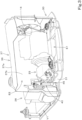
FIG. 2] FIG. 2 is a front perspective view illustrating a portion of a machine body. - [
FIG. 3] FIG. 3 is a back perspective view illustrating a portion of a machine body. - [
FIG. 4] FIG. 4 is a front perspective view illustrating a hose clamp structure. - [
FIG. 5] FIG. 5 is a front perspective view illustrating a place where a hose clamp is provided. - [
FIG. 6] FIG. 6 is an exploded perspective view of a place where a hose clamp is provided. - [
FIG. 7] FIG. 7 is an exploded perspective view of a cover member and the like. - [
FIG. 8] FIG. 8 is an exploded perspective view of a hose clamp. - [
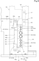
FIG. 9] FIG. 9 is a front view illustrating a hose clamp structure. - [
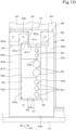
FIG. 10] FIG. 10 is a front view illustrating a clamp structure. - [
FIG. 11] FIG. 11 is a back view illustrating a hose clamp structure. - [
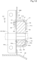
FIG. 12] FIG. 12 is a plan sectional view illustrating a hose clamp structure. - [
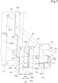
FIG. 13] FIG. 13 is a side sectional view illustrating a hose clamp structure. - [
FIG. 14] FIG. 14 is a plan sectional view illustrating an example of a method of mounting a hose. - Hereinafter, an embodiment of the present invention will be described with reference to the drawings as appropriate.
-
FIG. 1 is a schematic side view illustrating an overall configuration of aworking machine 1 according to the present embodiment. In the present embodiment, a backhoe, which is a turning working machine, is exemplified as theworking machine 1. - As illustrated in
FIG. 1 , theworking machine 1 includes a machine body (turning base) 2, atraveling device 3, and aworking device 4. An operator'sseat 6 on which an operator (driver) is seated is mounted on themachine body 2. - In the present embodiment, a direction toward the front of the operator seated on the operator's
seat 6 of the working machine 1 (arrow A1 direction inFIG. 1 ) is described as a forward side (machine-body forward side), a direction toward the rear of the operator (arrow A2 direction inFIG. 1 ) is described as a rearward side (machine-body rearward side), and an arrow K1 direction inFIG. 1 is described as a front-rear direction (machine-body front-rear direction). Also, a direction toward the left of the operator (near side inFIG. 1 ) is described as a leftward side, and a direction toward the right of the operator (far side inFIG. 1 ) is described as a rightward side. - Also, a horizontal direction that is a direction perpendicular to the front-rear direction K1 is described as a machine-body width direction. A direction from a center portion to a right portion or a left portion in a width direction of the
machine body 2 is described as an outward side in the machine-body width direction. That is, the outward side in the machine-body width direction is a direction away from the center in the width direction of themachine body 2 in the machine-body width direction. A direction opposite to the outward side in the machine-body width direction is described as an inward side in the machine-body width direction. That is, the inward side in the machine-body width direction is a direction toward the center in the width direction of themachine body 2 in the machine-body width direction. - As illustrated in
FIG. 1 , thetraveling device 3 is a crawler type traveling device that supports themachine body 2 so as to be travelable, and includes a travelingframe 3A, afirst traveling device 3L provided on the left of thetraveling frame 3A, and asecond traveling device 3R provided on the right of thetraveling frame 3A. Thefirst traveling device 3L and the second travelingdevice 3R are driven by a traveling motor M1 including a hydraulic motor (hydraulic actuator). In the present embodiment, the crawlertype traveling device 3 is used, but this does not imply any limitation, and a wheel type traveling device or the like may be used. Adozer device 7 is attached to a front portion of thetraveling device 3. Thedozer device 7 can be driven by a dozer cylinder including a hydraulic cylinder (hydraulic actuator). - As illustrated in
FIG. 1 , themachine body 2 is supported on thetraveling device 3 via a turning bearing 8 so as to be turnable about a turning axis X1 that is an axis extending in an up-down direction. Additionally, themachine body 2 includes, in a front portion thereof, asupport bracket 9 and aswing bracket 10 that support theworking device 4. Thesupport bracket 9 is provided so as to protrude forward from themachine body 2. Theswing bracket 10 is attached to a front portion of thesupport bracket 9 so as to be swingable about a vertical axis (an axis extending in the up-down direction). - As illustrated in
FIG. 1 , theworking device 4 includes aboom 11, anarm 12, and abucket 13. A base portion of theboom 11 is pivotally attached to an upper portion of theswing bracket 10 so as to be rotatable about a lateral axis (an axis extending in the machine-body width direction). Thearm 12 is pivotally attached to a distal end side of theboom 11 so as to be rotatable about a lateral axis. Thebucket 13 is provided at a distal end side of thearm 12 so as to be capable of performing shoveling and dumping. The shoveling is a motion of swinging thebucket 13 in a direction toward theboom 11, and is, for example, a motion of shoveling earth and sand or the like. Also, the dumping is a motion of swinging thebucket 13 in a direction away from theboom 11, and is, for example, a motion of dropping (discharging) shoveled earth and sand or the like. - Instead of or in addition to the
bucket 13, another working tool (hydraulic attachment) that can be driven by a hydraulic actuator can be attached to the workingmachine 1. Examples of the other working tool include a hydraulic breaker, a hydraulic crusher, an angle broom, an earth auger, a pallet fork, a sweeper, a mower, and a snow blower. - The
swing bracket 10 is swingable by expansion and contraction of a swing cylinder (not illustrated). Theboom 11 is swingable by expansion and contraction of a boom cylinder C2. Thearm 12 is swingable by expansion and contraction of an arm cylinder C3. Thebucket 13 is capable of performing shoveling and dumping by expansion and contraction of a bucket cylinder C4. The swing cylinder, the boom cylinder C2, the arm cylinder C3, and the bucket cylinder C4 include hydraulic cylinders (hydraulic actuators). - As illustrated in
FIG. 1 , a prime mover E1 is mounted in a rear portion of themachine body 2. The prime mover E1 is a diesel engine. Alternatively, the prime mover E1 may be a gasoline engine or an electric motor, or may be a hybrid type including an engine and an electric motor. Anoperation unit 18 including the operator'sseat 6, a travelinglever 16 located forward of the operator'sseat 6, a manipulatingdevice 17L located leftward of the operator'sseat 6, a manipulatingdevice 17R located rightward of the operator'sseat 6, and the like is mounted on a forward of the prime mover E1 of themachine body 2. The travelinglever 16 is an operation member that operates the travelingdevice 3. The manipulatingdevices boom 11, a swinging operation of thearm 12, operations of shoveling and dumping of thebucket 13, a turning operation of themachine body 2, and the like. Astep 21 that defines a floor surface is provided on an upper surface side of themachine body 2 and a forward side of the operator'sseat 6. - As illustrated in
FIG. 2 , themachine body 2 includes a turningframe 30 serving as a framework. The turningframe 30 includes a turning base plate (base plate) 31 that defines a bottom portion of themachine body 2, a reinforcingrib 32 that reinforces the turningbase plate 31, thesupport bracket 9, and a weight 33 (seeFIG. 1 ). Additionally, the turningframe 30 includes brackets, stays, and the like for attaching devices, tanks, other components, and the like mounted on themachine body 2. - The turning
base plate 31 is formed of a thick steel plate or the like. The brackets, stays, and the like provided on the turningframe 30 are fixed onto the turningbase plate 31 by welding or the like. The turningbase plate 31 is supported on the travelingdevice 3 via the turning bearing 8 so as to be rotatable about the turning axis X1. - The reinforcing
rib 32 is formed of a plate member and is provided on the turningbase plate 31 to extend from a front portion toward a rear portion. Specifically, the reinforcingrib 32 includes a firstvertical rib 32R extending rearward from a rear portion of a left portion of thesupport bracket 9 provided on the front portion of the turningbase plate 31, and a secondvertical rib 32L extending rearward from a rear portion of a right portion of thesupport bracket 9. - As illustrated in
FIG. 2 , a control valve V1, ahydraulic fluid tank 28, a turningmotor 20, and the like are attached on the turningbase plate 31. - The control valve V1 is located on a front portion of a left portion of the turning
base plate 31. The control valve V1 controls the flow rate of a hydraulic fluid to be supplied to the hydraulic actuators provided in the workingmachine 1 and driven with the hydraulic fluid. Specifically, the control valve V1 is a valve unit in which control valves that control the flow rate of the hydraulic fluid to be supplied to each of the hydraulic actuators provided in the workingmachine 1 are collected. - The
hydraulic fluid tank 28 is located rearward of the control valve V1. Thehydraulic fluid tank 28 is a tank that stores the hydraulic fluid. - As illustrated in
FIG. 3 , the prime mover E1 is mounted on the rear portion of the turningbase plate 31. Ahydraulic pump 25 is attached to a one-side portion (left portion) in the machine-body width direction of the prime mover E1. Thehydraulic pump 25 is driven by power of the prime mover E1. Thehydraulic pump 25 sucks the hydraulic fluid in thehydraulic fluid tank 28 and delivers the hydraulic fluid (pressure oil) for driving the hydraulic actuators such as hydraulic motors, hydraulic cylinders, and the like provided in the workingmachine 1. Also, thehydraulic pump 25 delivers a pilot pressure for actuating a hydraulic valve and a hydraulic pressure for a signal. - A cooling
fan 14 is provided on a right portion of the prime mover E1, and a radiator, an oil cooler, a fuel cooler, and the like are located rightward of the coolingfan 14. - As illustrated in
FIG. 3 , apartition wall 36 that defines a front portion side of a prime mover chamber E2 that houses the prime mover E1 is provided forward of the prime mover E1. In other words, thepartition wall 36 is a member that separates the prime mover chamber E2 from the front of the prime mover chamber E2 (the outside of the prime mover chamber E2). As illustrated inFIG. 5 , thehydraulic fluid tank 28 is located leftward of thepartition wall 36. Thehydraulic fluid tank 28 is installed on the turningbase plate 31. - As illustrated in
FIG. 5 , thepartition wall 36 includes a partition wallmain body 37 and apartition plate 38. The partition wallmain body 37 is a member that separates the prime mover chamber E2 from the upper front of the prime mover chamber E2, and includes anupper wall 37a and afront wall 37b extending downward from a front portion of theupper wall 37a. - As illustrated in
FIG. 5 , thepartition plate 38 is located lower than the partition wallmain body 37. Also, thepartition plate 38 is located lower than thestep 21. That is, thepartition plate 38 is a member that partitions the lower front of the prime mover chamber E2. Thepartition plate 38 includes afirst partition plate 38A and asecond partition plate 38B. Thefirst partition plate 38A is erected on the turningbase plate 31 such that plate surfaces face in the front-rear direction K1. Also, thefirst partition plate 38A is located on the turningbase plate 31 so as to extend in the machine-body width direction and is fixed to the turningbase plate 31 by welding or the like. Thesecond partition plate 38B has a lower portion fixed to a back surface of thefirst partition plate 38A by welding or the like, and a left portion fixed to the turningbase plate 31 by welding or the like. A lower portion of the partition wall main body 37 (a lower portion of thefront wall 37b) is attached to thesecond partition plate 38B. As illustrated inFIG. 6 , thesecond partition plate 38B protrudes leftward of thefirst partition plate 38A. - As illustrated in
FIGS. 5 and6 , acover member 39 and ahose clamp 43 are provided between thepartition wall 36 and thehydraulic fluid tank 28. Thehose clamp 43 is located lower than thecover member 39. Thecover member 39 and thehose clamp 43 close a space between thepartition wall 36 and thehydraulic fluid tank 28. Thecover member 39 and thehose clamp 43 define a portion of thepartition wall 36. - As illustrated in
FIGS. 6 and7 , thecover member 39 includes afirst cover 40, asecond cover 41, and athird cover 42. Thefirst cover 40 is formed in a rectangular shape having an angularU-shaped cutout groove 40a that opens leftward. Thecutout groove 40a is for passing a routing member such as a harness obtained by bundling wires, and a space between thecutout groove 40a and the harness is sealed with a grommet. Thesecond cover 41 includes afirst portion 41a, asecond portion 41b, and a third portion (extension portion) 41c. Thefirst portion 41a is fixed to a lower end portion and a front surface side of thefirst cover 40 by welding or the like. Thesecond portion 41b is fixed to a left end portion and the front surface side of thefirst cover 40 by welding or the like to be located lower than thecutout groove 40a. Thethird portion 41c extends downward from a left portion of thefirst portion 41a. Thethird cover 42 is formed in a rectangular shape having an angularU-shaped cutout groove 42a that opens downward. Thecutout groove 42a is formed slightly rightward of a center portion in the machine-body width direction of thethird cover 42. An upper portion of thethird cover 42 is fixed to a front surface of thesecond portion 41b of thesecond cover 41 by welding or the like. Thecutout groove 42a is displaced rightward with respect to thethird portion 41c of thesecond cover 41. Thecutout groove 42a is a groove for avoiding interference between thethird cover member 42 and anupper attachment plate 57A of a pressing member 48 (described later). - The
first cover 40 is bolted to thefront wall 37b of the partition wallmain body 37, and thesecond cover 41 is bolted to aflange plate 44 fixed to thehydraulic fluid tank 28 by welding or the like so as to protrude outward from thehydraulic fluid tank 28. Acutout portion 44a for avoiding interference with a groove portion 50 (described later) is formed in a lower portion of the flange plate 44 (seeFIG. 11 ). - The
third cover 42 is bolted to thesecond partition plate 38B and theflange plate 44 together with a vertical plate 49 (described later). - As illustrated in
FIGS. 2 ,3 , and4 , thehose clamp 43 holds hoses such as hydraulic hose(s) 45 guided to an area forward of thepartition wall 36 from the prime mover E1 (guided to the outside of the prime mover E1). Thehose clamp 43 is provided between thepartition plate 38 and thehydraulic fluid tank 28. Thus, thehose clamp 43 is located lower than the step 21 (inside the machine body 2) together with the control valve V1. The hydraulic hose(s) 45 held by thehose clamp 43 may be a plurality ofhydraulic hoses 45. Most of the plurality ofhydraulic hoses 45 are hoses that connect thehydraulic pump 25 and the control valve V1. As illustrated inFIG. 4 , in the present embodiment, the number of the plurality ofhydraulic hoses 45 is seven. The sevenhydraulic hoses 45 are arranged in the up-down direction, and two upperhydraulic hoses 45a and three lowerhydraulic hoses 45a are small-diameter hoses each having a diameter smaller than the diameter of each of two middlehydraulic hoses 45b. - As illustrated in
FIG. 6 , thehose clamp 43 includes a holdingbody 46 attached directly or indirectly to amachine body 2, aclamping tool 47 that is held by the holdingbody 46 and that holds thehydraulic hoses 45, and a pressingmember 48 that presses theclamping tool 47. - As illustrated in
FIG. 8 , the holdingbody 46 includes avertical plate 49, agroove portion 50, areceiver portion 51, and acoupling plate 52. - As illustrated in
FIG. 8 , thevertical plate 49 is located such that plate surfaces face in the front-rear direction K1. That is, thevertical plate 49 is located such that a plate width direction (plate-surface parallel direction) W1 perpendicular to the up-down direction coincides with the machine-body width direction, and a plate thickness direction coincides with the front-rear direction K1. Thevertical plate 49 has anopening 53 and aninsertion groove 54. Specifically, thevertical plate 49 includes a firstvertical wall portion 49a that is a portion (left portion) provided on one of opposite sides in the plate width direction W1 (on the left of the opposite sides in the machine-body width direction, on the right inFIG. 8 ), a secondvertical wall portion 49b that is a portion (right portion) provided on the other of the opposite sides in the plate width direction W1 (on the right of the opposite sides in the machine-body width direction, on the left inFIG. 8 ) and that is spaced from the firstvertical wall portion 49a in the plate width direction W1, anextension wall 49c extending from an upper portion of the secondvertical wall portion 49b toward an upper portion of the firstvertical wall portion 49a, and alower portion wall 49d that couples a lower portion of the firstvertical wall portion 49a and a lower portion of the secondvertical wall portion 49b. A space is provided between theextension wall 49c and the upper portion of the firstvertical wall portion 49a. - As illustrated in
FIG. 8 , theopening 53 is defined by the firstvertical wall portion 49a, the secondvertical wall portion 49b, theextension wall 49c, and thelower portion wall 49d. In other words, theopening 53 includes a first edge (left edge) 53a that is one of opposite edges in the plate width direction W1, a second edge (right edge) 53b that is the other of opposite edges in the plate width direction W1, anupper edge 53c, and alower edge 53d. Theinsertion groove 54 is defined between theextension wall 49c and the upper portion of the firstvertical wall portion 49a. That is, theinsertion groove 54 extends from an upper end of thevertical plate 49 toward theopening 53 to communicate with theopening 53. Also, theinsertion groove 54 has a groove width W2 that allows thehydraulic hoses 45 held by thehose clamp 43 to pass therethrough in a direction perpendicular to a longitudinal direction of thehydraulic hoses 45. - As illustrated in
FIGS. 7 and9 , thethird cover 42 is superposed on an upper portion at an obverse side (front side) of thevertical plate 49, and thevertical plate 49 is bolted to thesecond partition plate 38B and theflange plate 44 together with thethird cover 42. As illustrated inFIGS. 9 and10 , thecutout groove 42a of thethird cover 42 is located at a position corresponding to theextension wall 49c of thevertical plate 49. - As illustrated in
FIGS. 10 and11 , thethird portion 41c of thesecond cover 41 is inserted into theinsertion groove 54. Also, thethird portion 41c slightly protrudes from theinsertion groove 54 toward theopening 53. - Also, as illustrated in
FIG. 8 , thevertical plate 49 is provided with a fixingwall 49e extending forward from a lower end of thelower portion wall 49d. As illustrated inFIG. 4 , the fixingwall 49e is bolted onto the turningbase plate 31. - When the
vertical plate 49 and thecover member 39 are mounted, for example, first, the fixingwall 49e of thevertical plate 49 is bolted to the turningbase plate 31, and then thecover member 39 is placed such that thethird cover 42 is located on a front surface of the upper portion of thevertical plate 49. Then, thefirst cover 40 is bolted to thefront wall 37b, thesecond cover 41 is bolted to theflange plate 44, and thethird cover 42 and thevertical plate 49 are bolted together to thesecond partition plate 38B and theflange plate 44. Alternatively, any of thefirst cover 40, thesecond cover 41, and thethird cover 42 may be fixed first. Still alternatively, the fixingwall 49e of thevertical plate 49 may be bolted to the turningbase plate 31 after thethird cover 42 and thevertical plate 49 are fastened together. - Note that the
vertical plate 49 is not limited to the above-described configuration, and, for example, theextension wall 49c may be connected to the upper portion of the firstvertical wall portion 49a. That is, theinsertion groove 54 is not necessarily provided. Also, the firstvertical wall portion 49a and the secondvertical wall portion 49b are not limited to the configuration in which they extend in the up-down direction, and they may extend in the horizontal direction or an oblique direction. In other words, thevertical plate 49 may be placed such that the plate width direction W1 coincides with the up-down direction or an oblique direction inclined with respect to the up-down direction. - As illustrated in
FIGS. 8 ,10 ,11 , and12 , thegroove portion 50 is provided at a back side of the vertical plate 49 (at the same side of thevertical plate 49 as theback surface 49f) at one of opposite portions in the plate width direction W1 of thevertical plate 49 such that thegroove portion 50 is adjacent to theopening 53. Specifically, thegroove portion 50 includes afirst portion 50a, asecond portion 50b, and athird portion 50c. Thefirst portion 50a is a right portion of the firstvertical wall portion 49a of thevertical plate 49. In other words, thefirst portion 50a is a portion of thevertical plate 49 that defines one of opposite edges (thefirst edge 53a) of theopening 53. Thesecond portion 50b faces thefirst portion 50a with a space therebetween at the back side (at the same side of thevertical plate 49 as theback surface 49f) of thefirst portion 50a (vertical plate 49). Thethird portion 50c extends from one of opposite edges (left edge) of thesecond portion 50b in the plate width direction W1 toward theback surface 49f of thefirst portion 50a (vertical plate 49) and is fixed to thefirst portion 50a (vertical plate 49) by welding or the like. Thus, thegroove portion 50 is open (opened) toward the opening 53 (rightward) in the plate width direction W1. Also, thegroove portion 50 extends in the up-down direction. Afirst extension wall 50d is provided at an upper end portion of thethird portion 50c to extend rightward from the upper end portion. - The
receiver portion 51 is provided at the back side of the vertical plate 49 (at the same side of thevertical plate 49 as theback surface 49f) at the other of the opposite portions in the plate width direction W1 of the vertical plate 49 (at the other of the opposite sides of the opening 53). Specifically, thereceiver portion 51 includes afirst wall portion 51a and asecond wall portion 51b. Thefirst wall portion 51a faces theopening 53 at the back side (at the same side of thevertical plate 49 as theback surface 49f) of thevertical plate 49. Thesecond wall portion 51b extends from one of opposite edges (right edge) of thefirst wall portion 51a in the plate width direction W1 toward theback surface 49f of thevertical plate 49 and is fixed to thevertical plate 49 by welding or the like. A left surface of thesecond wall portion 51b is substantially flush with thesecond edge 53b of theopening 53. Also, thereceiver portion 51 extends in the up-down direction. Asecond extension wall 51c is formed at an upper end portion of thesecond wall portion 51b to extend leftward (toward thefirst extension wall 50d) from the upper end portion. Thefirst extension wall 50d and thesecond extension wall 51c are provided with a space therebetween. - The
coupling plate 52 is in a band plate shape that is long in the plate width direction W1 with plate surfaces facing in the up-down direction, and couples a lower end of thethird portion 50c and a lower end of thesecond wall portion 51b. - The pressing
member 48 includes amain plate 56 and at least oneattachment plate 57. Themain plate 56 is formed of a band plate member that is long in the up-down direction and whose plate surfaces face in the front-rear direction K1. Themain plate 56 is inserted in theopening 53 to press a second clamping member 59 (described later). Theattachment plate 57 is fixed to themain plate 56 by welding or the like, comes into contact with a front surface of thevertical plate 49, and is attached to thevertical plate 49 by abolt 61. As illustrated inFIG. 8 , themain plate 56 is formed to have a length in the up-down direction that allows themain plate 56 to be inserted into theopening 53 and that is substantially equal to a dimension in the up-down direction of theopening 53. Theattachment plate 57 is provided on each of an upper portion and a lower portion of themain plate 56. That is, theattachment plate 57 includes a pair ofattachment plates 57. Anupper attachment plate 57A has a lower portion fixed to a front surface of themain plate 56 by welding or the like, and an upper portion protruding upward from themain plate 56. Alower attachment plate 57B has an upper portion fixed to the front surface of themain plate 56 by welding or the like, and a lower portion protruding downward from themain plate 56. Thus, when theattachment plates vertical plate 49 and attached to thevertical plate 49, themain plate 56 is brought into a state inserted into theopening 53. - As illustrated in
FIG. 8 , theclamping tool 47 includes afirst clamping member 58 and asecond clamping member 59. Thefirst clamping member 58 and thesecond clamping member 59 are made of elastic members such as rubber. Theclamping tool 47 has seveninsertion holes 60 arranged in the up-down direction, through which the sevenhydraulic hoses 45 are inserted in the front-rear direction K1. Theclamping tool 47 is divided into a left first clampingmember 58 and a rightsecond clamping member 59 in a form of dividing eachinsertion hole 60 into two portions on the left and right. Thus, thehydraulic hoses 45 can be held by the first clampingmember 58 and thesecond clamping member 59 sandwiching thehydraulic hoses 45 so that thehydraulic hoses 45 are inserted through the insertion holes 60. Also, a width W3 in the plate width direction W1 of the first clampingmember 58 is narrower than a width W4 in the plate width direction W1 of thesecond clamping member 59. Also, athickness 59a of the second clamping member 59 (a dimension in a direction perpendicular to the plate width direction W1 and the up-down direction) is thicker than athickness 58a of thefirst clamping members 58. - As illustrated in
FIG. 10 , the first clampingmember 58 is a member to be inserted in thegroove portion 50. A length in the up-down direction of the first clampingmember 58 is formed as a length extending from thefirst extension wall 50d to thecoupling plate 52. As illustrated inFIG. 12 , thethickness 58a of the first clampingmember 58 is a thickness that allows the first clampingmember 58 to be inserted into thegroove portion 50 and is substantially equal to agroove width 50e of thegroove portion 50. - As illustrated in
FIG. 10 , the first clampingmember 58 has a left portion inserted into thegroove portion 50, and a right portion protruding from thegroove portion 50. Halves of the insertion holes 60 are formed in the portion of the first clampingmember 58 protruding from thegroove portion 50. - The
second clamping member 59 is placed through the opening 53 from the front side (forward side) of thevertical plate 49 with the first clampingmember 58 being inserted in thegroove portion 50 to contact a front surface of thefirst wall portion 51a and the left surface of thesecond wall portion 51b of the receiver portion 51 (contact the receiver portion 51). As illustrated inFIG. 14 , thethickness 59a of thesecond clamping member 59 is a dimension larger than a distance H1 from the front surface of thefirst wall portion 51a to theback surface 49f of thevertical plate 49. That is, thesecond clamping member 59 has a thickness such that thesecond clamping member 59 protrudes forward through theback surface 49f of thevertical plate 49 via theopening 53 when thesecond clamping member 59 is not pressed by the pressingmember 48. Halves of the insertion holes 60 are in the left portion of the first clampingmember 58. The right portion of the first clampingmember 58 is a portion with which themain plate 56 of the pressingmember 48 comes into contact. - As illustrated in
FIG. 8 , thesecond clamping member 59 is divided into three portions in the up-down direction. Anupper portion 59b is a portion corresponding to two of the insertion holes 60 on an upper portion side among the seveninsertion holes 60, amiddle portion 59c is a portion corresponding to two of the insertion holes 60 in a middle portion among the seveninsertion holes 60, and alower portion 59d is a portion corresponding to three of the insertion holes 60 on a lower portion side among the seven insertion holes 60. - Various methods are conceivable for mounting the
hydraulic hoses 45 to thehose clamp 43. - For example, the
hydraulic hoses 45 can be held by mounting theclamping tool 47 and the pressingmember 48 to the holdingbody 46 in a state in which thecover member 39 and the holdingbody 46 are attached. - In this case, as illustrated in the drawing on the left of
FIG. 14 , first, the first clampingmember 58 is inserted into thegroove portion 50. Then, thehydraulic hoses 45 passed through theopening 53 are fitted to portions of the first clampingmember 58 where the insertion holes 60 are provided (portions corresponding to halves of the insertion holes 60). Then, as illustrated in the drawing on the right ofFIG. 14 , thesecond clamping member 59 is placed through the opening 53 from the front side of thevertical plate 49 to contact the receiver portion 51 (thefirst wall portion 51a and thesecond wall portion 51b), and thehydraulic hoses 45 are held by the first clampingmember 58 and thesecond clamping member 59. At this time (in a state before thesecond clamping member 59 is pressed by the pressing member 48), thesecond clamping member 59 protrudes on the front surface side with respect to theback surface 49f of thevertical plate 49 via theopening 53. Then, the pressingmember 48 is bolted to thevertical plate 49. In so doing, as illustrated inFIG. 12 , themain plate 56 of the pressingmember 48 is inserted in theopening 53, and presses thesecond clamping member 59 from the front side (the side opposite the receiver portion 51) to elastically deform thesecond clamping member 59. Since thesecond clamping member 59 is elastically deformed, thehydraulic hoses 45 and the first clampingmember 58 are pressed by thesecond clamping member 59, and thehydraulic hoses 45 are firmly held by thehose clamp 43. - With this, since the
hydraulic hoses 45 are sandwiched and fixed by the first clampingmember 58 and thesecond clamping member 59 by thesecond clamping member 59 being elastically deformed, it is possible to suppress pulsation of thehydraulic hoses 45 and to improve vibration damping property. Also, since thesecond clamping member 59 is elastically deformed, it is possible to secure sealing property and to prevent or reduce the entry of hot air from the prime mover chamber E2 into themachine body 2. Also, since the first clampingmember 58 and thesecond clamping member 59 can be easily removed only by removing the pressingmember 48, thehydraulic hoses 45 can be easily removed. - Alternatively, as a method of mounting the
hydraulic hoses 45 to thehose clamp 43, it is conceivable to hold thehydraulic hoses 45 by thehose clamp 43 before the prime mover E1 is mounted to themachine body 2. - In this case, the
hose clamp 43 is mounted on themachine body 2 side after the prime mover E1 is mounted to themachine body 2. Specifically, first, before the prime mover E1 is mounted to themachine body 2, thehydraulic hoses 45 are inserted through theopening 53, thehydraulic hoses 45 are sandwiched by the first clampingmember 58 and thesecond clamping member 59, and then the pressingmember 48 is attached to hold thehydraulic hoses 45 by thehose clamp 43. Then, the prime mover E1 is lowered onto the turningbase plate 31 and installed on the turningbase plate 31 while thehose clamp 43 in a state of holding thehydraulic hoses 45 is placed on the prime mover E1. Thereafter, for example, thehose clamp 43 is located forward of the installation position, and the partition wallmain body 37 and thehydraulic fluid tank 28 are mounted. Then, for example, the fixingwall 49e of thehose clamp 43 to which thehydraulic hoses 45 have been mounted is bolted to the turningbase plate 31. Thereafter, thecover member 39 is placed such that thethird cover 42 is located on the front surface of the upper portion of thevertical plate 49, thefirst cover 40 is bolted to thefront wall 37b, and thesecond cover 41 is bolted to theflange plate 44. Thereafter, thethird cover 42 and thevertical plate 49 are bolted together to thesecond partition plate 38B and theflange plate 44. Alternatively, thethird cover 42 and thevertical plate 49 may be fastened together first, and then thefirst cover 40 and thesecond cover 41 may be fixed. Still alternatively, thethird cover 42 and thevertical plate 49 may be fastened together, and then the fixingwall 49e of thevertical plate 49 may be bolted to the turningbase plate 31. - In this mounting method, the holding of the
hydraulic hoses 45 by thehose clamp 43 can be performed in a wide place, and hence workability is good. Also, thehydraulic hoses 45 can be inserted into theopening 53 via theinsertion groove 54, and hence the insertion of thehydraulic hoses 45 can be easily performed. - Alternatively or additionally, as a method of mounting the
hydraulic hoses 45 to thehose clamp 43, it is conceivable to hold thehydraulic hoses 45 by thehose clamp 43 in a state in which thecover member 39 is not attached. - In this case, for example, in a state in which the fixing
wall 49e of the holdingbody 46 is fixed to the turningbase plate 31, thehydraulic hoses 45 are inserted through theopening 53 via theinsertion groove 54, thehydraulic hoses 45 are sandwiched by the first clampingmember 58 and thesecond clamping member 59, and then the pressingmember 48 is attached. Then, thecover member 39 is mounted to fix an upper portion of the holdingbody 46. Alternatively or additionally, after thehydraulic hoses 45 are mounted to the holdingbody 46, the fixingwall 49c may be fixed to the turningbase plate 31. Additionally or alternatively, after thehydraulic hoses 45 are mounted to the holdingbody 46, thethird cover 42 and thevertical plate 49 may be bolted together to thesecond partition plate 38B and theflange plate 44, and then the fixingwall 49c may be fixed to the turningbase plate 31. Even in this mounting method, thehydraulic hoses 45 can be inserted through theopening 53 via theinsertion groove 54, and hence the insertion of thehydraulic hoses 45 can be easily performed. - A hose clamp structure as has been described includes a vertical plate 49 having an opening 53, a groove portion 50 provided at a back side (on the same side of the vertical plate 49 as its back surface 49f) of the vertical plate 49 on one of opposite sides of the opening 53 in a plate-surface parallel direction (plate width direction W1) such that the groove portion 50 is adjacent to the opening 53, the groove portion 50 being open toward the opening 53 in the plate-surface parallel direction (plate width direction W1), a receiver portion 51 provided at the back side (on the same side of the vertical plate 49 as its back surface 49f) of the vertical plate 49 on the other of the opposite sides of the opening 53 in the plate-surface parallel direction (plate width direction W1), a first clamping member 58 to be inserted in the groove portion 50, a second clamping member 59 made of an elastic member and configured such that the second clamping member 59 is placed in the receiver portion 51 through the opening 53 from a front side of the vertical plate 49 to contact the receiver portion 51 with the first clamping member 58 being inserted in the groove portion 50 and such that at least one hose (hydraulic hose 45) passing through the opening 53 is held between the first clamping member 58 and the second clamping member 59, and a pressing member 48 to be attached to the vertical plate 49 to press the second clamping member 59 from the front side of the vertical plate 49 to elastically deform the second clamping member 59 to cause the second clamping member 59 to press the first clamping member 58.
- With this configuration, hose(s) (hydraulic hose(s) 45) can be easily removed by simply removing the pressing
member 48 from thevertical plate 49. Also, since thehydraulic hose 45 is fixed by being clamped between the first clampingmember 58 and thesecond clamping member 59 by elastically deforming thesecond clamping member 59, it is possible to prevent or reduce the pulsation of thehose 45 which is a hydraulic hose and to improve vibration damping properties. - The
first clamping member 58 has a thickness substantially equal to agroove width 50e of thegroove portion 50. Thesecond clamping member 59 has a thickness such that thesecond clamping member 59 protrudes forward through aback surface 49f of thevertical plate 49 via theopening 53 when thesecond clamping member 59 is in contact with thereceiver portion 51 but is not pressed by the pressingmember 48. The pressingmember 48 includes amain plate 56 to be inserted in theopening 53 to press thesecond clamping member 59, and anattachment plate 57 fixed to themain plate 56 to contact a front surface of thevertical plate 49 and attached to thevertical plate 49. - With this configuration, the first clamping
member 58 can be easily mounted. - The
vertical plate 49 has aninsertion groove 54 extending from an outer edge of thevertical plate 49 toward theopening 53 to communicate with theopening 53 and configured to allow the at least onehose 45 to pass through theinsertion groove 54 in a direction perpendicular to a longitudinal direction of the at least onehose 45. - With this configuration, the
hose 45 can be easily passed through theopening 53 via theinsertion groove 54. - The
groove portion 50 includes afirst portion 50a which is a portion of thevertical plate 49 that defines one of opposite edges (first edge 53a) of theopening 53 in the plate-surface parallel direction (plate width direction W1), asecond portion 50b facing thefirst portion 50a at the back side (on the same side of thevertical plate 49 as itsback surface 49f) of thevertical plate 49, and athird portion 50c extending from one of opposite edges of thesecond portion 50b in the plate-surface parallel direction (plate width direction W1) toward aback surface 49f of thevertical plate 49 and fixed to thevertical plate 49. - With this configuration, a portion of the
vertical plate 49 functions as a portion of thegroove portion 50, and thus it is possible to simplify the structure. - The
receiver portion 51 includes afirst wall portion 51a facing theopening 53 at the back side (on the same side of thevertical plate 49 as itsback surface 49f) of thevertical plate 49, and asecond wall portion 51b extending from one of opposite edges of thefirst wall portion 51a in the plate-surface parallel direction (plate width direction W1) toward aback surface 49f of thevertical plate 49 and fixed to thevertical plate 49. Thesecond clamping member 59 is placed to contact thefirst wall portion 51a and thesecond wall portion 51b through the opening 53 from the front side of thevertical plate 49. - With this configuration, the
second clamping member 59 can be properly elastically deformed by being clamped between the pressingmember 48 and thefirst wall portion 51a. - A working
machine 1 includes amachine body 2, a prime mover E1 on themachine body 2, apartition wall 36 to separate a prime mover chamber E2 housing the prime mover E1 from an outside of the prime mover chamber E2, and one of the above-described hose clamp structures, wherein thevertical plate 49 defines a portion of thepartition wall 36, and the at least onehose 45 is guided from the prime mover chamber E2 to an outside of thepartition wall 36. - While embodiments of the present invention have been described above, it is to be understood that the embodiments disclosed herein are considered as examples in all aspects and are not considered as limitations. The scope of the present invention is to be determined not by the foregoing description but by the claims, and is intended to include all variations and modifications within the scope of the claims and their equivalents.
-
- 1
- Working machine
- 2
- Machine body
- 36
- Partition wall
- 45
- Hose (hydraulic hose)
- 48
- Pressing member
- 49
- Vertical plate
- 49f
- Back surface
- 50
- Groove portion
- 50a
- First portion
- 50b
- Second portion
- 50c
- Third portion
- 50e
- Groove width
- 51
- Receiver portion
- 51a
- First wall portion
- 51b
- Second wall portion
- 53
- Opening
- 53a
- First edge
- 54
- Insertion groove
- 56
- Main plate
- 57
- Attachment plate
- 58
- First clamping member
- 59
- Second clamping member
- E1
- Prime mover
- E2
- Prime mover chamber
- W1
- Plate-surface parallel direction (plate width direction)
Claims (6)
- A hose clamp structure comprising:a vertical plate having an opening;a groove portion provided at a back side of the vertical plate on one of opposite sides of the opening in a plate-surface parallel direction such that the groove portion is adjacent to the opening, the groove portion being open toward the opening in the plate-surface parallel direction;a receiver portion provided at the back side of the vertical plate on the other of the opposite sides of the opening in the plate-surface parallel direction;a first clamping member to be inserted in the groove portion;a second clamping member made of an elastic member and configured such that the second clamping member is placed in the receiver portion through the opening from a front side of the vertical plate to contact the receiver portion with the first clamping member being inserted in the groove portion and such that at least one hose passing through the opening is held between the first clamping member and the second clamping member; anda pressing member to be attached to the vertical plate to press the second clamping member from the front side of the vertical plate to elastically deform the second clamping member to cause the second clamping member to press the first clamping member.
- The hose clamp structure according to claim 1, whereinthe first clamping member has a thickness substantially equal to a groove width of the groove portion;the second clamping member has a thickness such that the second clamping member protrudes forward through a back surface of the vertical plate via the opening when the second clamping member is in contact with the receiver portion but is not pressed by the pressing member; andthe pressing member includes a main plate to be inserted in the opening to press the second clamping member, and an attachment plate fixed to the main plate to contact a front surface of the vertical plate and attached to the vertical plate.
- The hose clamp structure according to claim 1 or 2, wherein the vertical plate has an insertion groove extending from an outer edge of the vertical plate toward the opening to communicate with the opening and configured to allow the at least one hose to pass through the insertion groove in a direction perpendicular to a longitudinal direction of the at least one hose.
- The hose clamp structure according to any one of claims 1 to 3, wherein the groove portion includes a first portion which is a portion of the vertical plate that defines one of opposite edges of the opening in the plate-surface parallel direction, a second portion facing the first portion at the back side of the vertical plate, and a third portion extending from one of opposite edges of the second portion in the plate-surface parallel direction toward a back surface of the vertical plate and fixed to the vertical plate.
- The hose clamp structure according to any one of claims 1 to 4, whereinthe receiver portion includes a first wall portion facing the opening at the back side of the vertical plate, and a second wall portion extending from one of opposite edges of the first wall portion in the plate-surface parallel direction toward a back surface of the vertical plate and fixed to the vertical plate; andthe second clamping member is placed to contact the first wall portion and the second wall portion through the opening from the front side of the vertical plate.
- A working machine comprising:a machine body;a prime mover on the machine body;a partition wall to separate a prime mover chamber housing the prime mover from an outside of the prime mover chamber; andthe hose clamp structure according to any one of claims 1 to 5, whereinthe vertical plate defines a portion of the partition wall; andthe at least one hose is guided from the prime mover chamber to an outside of the partition wall.
Applications Claiming Priority (2)
| Application Number | Priority Date | Filing Date | Title |
|---|---|---|---|
| JP2021107840 | 2021-06-29 | ||
| PCT/JP2022/014354 WO2023276349A1 (en) | 2021-06-29 | 2022-03-25 | Hose clamp structure and work machine |
Publications (2)
| Publication Number | Publication Date |
|---|---|
| EP4365370A1 true EP4365370A1 (en) | 2024-05-08 |
| EP4365370A4 EP4365370A4 (en) | 2025-06-11 |
Family
ID=84692637
Family Applications (1)
| Application Number | Title | Priority Date | Filing Date |
|---|---|---|---|
| EP22832510.6A Pending EP4365370A4 (en) | 2021-06-29 | 2022-03-25 | FLEXIBLE PIPE CLAMPING STRUCTURE AND CONSTRUCTION MACHINERY |
Country Status (5)
| Country | Link |
|---|---|
| US (1) | US20240125095A1 (en) |
| EP (1) | EP4365370A4 (en) |
| JP (1) | JP7543565B2 (en) |
| CN (1) | CN117178096B (en) |
| WO (1) | WO2023276349A1 (en) |
Family Cites Families (15)
| Publication number | Priority date | Publication date | Assignee | Title |
|---|---|---|---|---|
| JPS6151298U (en) * | 1984-09-10 | 1986-04-07 | ||
| JPS61179784U (en) * | 1985-04-27 | 1986-11-10 | ||
| GB2221736B (en) * | 1988-08-10 | 1992-08-19 | Hawke Cable Glands Ltd | Apparatus for sealing a service duct |
| JP2004028220A (en) * | 2002-06-26 | 2004-01-29 | Shin Caterpillar Mitsubishi Ltd | Clearance closing structure for partition |
| JP4614900B2 (en) * | 2006-03-02 | 2011-01-19 | 株式会社クボタ | Clamping device |
| EP1837572A1 (en) * | 2006-03-20 | 2007-09-26 | Beele Engineering B.V. | System for sealing a space between an inner wall of a tubular opening and at least one tube or duct at least partly received in the opening |
| EP2294265B9 (en) * | 2008-05-29 | 2012-09-05 | Clark Equipment Company | Quick release hose guide |
| JP5286305B2 (en) * | 2010-02-22 | 2013-09-11 | 川崎重工業株式会社 | Waterproof device for electric cable introduction part of railway vehicles |
| JP5177201B2 (en) * | 2010-10-20 | 2013-04-03 | コベルコ建機株式会社 | Piping clamp for construction machinery |
| US20140265157A1 (en) * | 2013-03-14 | 2014-09-18 | S. Bravo Systems, Inc. | Sump wall penetration fitting for flexible piping |
| JP6599193B2 (en) * | 2015-09-30 | 2019-10-30 | 株式会社クボタ | Clamp tool and working machine equipped with clamp tool |
| WO2019131721A1 (en) * | 2017-12-27 | 2019-07-04 | 株式会社クボタ | Work equipment and method for producing work equipment |
| JP6896604B2 (en) | 2017-12-27 | 2021-06-30 | 株式会社クボタ | Work machine |
| JP7019525B2 (en) * | 2018-06-29 | 2022-02-15 | 株式会社クボタ | Working machine |
| US11384867B2 (en) * | 2019-03-27 | 2022-07-12 | Great Plains Manufacturing, Inc. | Hydraulic hose clamp |
-
2022
- 2022-03-25 EP EP22832510.6A patent/EP4365370A4/en active Pending
- 2022-03-25 CN CN202280029261.9A patent/CN117178096B/en active Active
- 2022-03-25 JP JP2023531438A patent/JP7543565B2/en active Active
- 2022-03-25 WO PCT/JP2022/014354 patent/WO2023276349A1/en not_active Ceased
-
2023
- 2023-12-12 US US18/536,807 patent/US20240125095A1/en active Pending
Also Published As
| Publication number | Publication date |
|---|---|
| EP4365370A4 (en) | 2025-06-11 |
| US20240125095A1 (en) | 2024-04-18 |
| CN117178096A (en) | 2023-12-05 |
| WO2023276349A1 (en) | 2023-01-05 |
| CN117178096B (en) | 2026-03-13 |
| JP7543565B2 (en) | 2024-09-02 |
| JPWO2023276349A1 (en) | 2023-01-05 |
Similar Documents
| Publication | Publication Date | Title |
|---|---|---|
| US9016418B2 (en) | Construction machine | |
| US9074342B2 (en) | Work vehicle | |
| WO2002040782A1 (en) | Construction machine | |
| JPH1018347A (en) | Boom installing device of construction machine | |
| US9650757B2 (en) | Construction machine | |
| JP6952731B2 (en) | Construction machinery | |
| US20240125095A1 (en) | Hose clamp structure and working machine | |
| EP3396072B1 (en) | Compact construction machine | |
| JP2006082661A (en) | Construction machinery | |
| GB2419117A (en) | Frame structure of a work machine | |
| JP7039397B2 (en) | Turning work vehicle | |
| JP3693480B2 (en) | Upper swing body of hydraulic excavator | |
| JP2015232209A (en) | Working machine | |
| JP2000273904A (en) | Piping structure of rotating work machine | |
| JP6584974B2 (en) | Working machine | |
| JP6961635B2 (en) | Construction machinery | |
| JP4346428B2 (en) | Swivel work machine | |
| JPH09151483A (en) | Hydraulic excavator fuel tank mounting structure | |
| JP3718428B2 (en) | Pilot valve mounting structure | |
| JP2002155543A (en) | Turning work machine | |
| KR100629820B1 (en) | Construction machine | |
| JP2003285635A (en) | Work vehicle cooler device | |
| JP6908567B2 (en) | Construction machinery | |
| JP2000096612A (en) | Turning machine and cabin used for it | |
| JP3688950B2 (en) | Swivel excavator |
Legal Events
| Date | Code | Title | Description |
|---|---|---|---|
| STAA | Information on the status of an ep patent application or granted ep patent |
Free format text: STATUS: THE INTERNATIONAL PUBLICATION HAS BEEN MADE |
|
| PUAI | Public reference made under article 153(3) epc to a published international application that has entered the european phase |
Free format text: ORIGINAL CODE: 0009012 |
|
| STAA | Information on the status of an ep patent application or granted ep patent |
Free format text: STATUS: REQUEST FOR EXAMINATION WAS MADE |
|
| 17P | Request for examination filed |
Effective date: 20231214 |
|
| AK | Designated contracting states |
Kind code of ref document: A1 Designated state(s): AL AT BE BG CH CY CZ DE DK EE ES FI FR GB GR HR HU IE IS IT LI LT LU LV MC MK MT NL NO PL PT RO RS SE SI SK SM TR |
|
| DAV | Request for validation of the european patent (deleted) | ||
| DAX | Request for extension of the european patent (deleted) | ||
| A4 | Supplementary search report drawn up and despatched |
Effective date: 20250514 |
|
| RIC1 | Information provided on ipc code assigned before grant |
Ipc: F16L 5/14 20060101ALN20250508BHEP Ipc: E02F 9/22 20060101ALI20250508BHEP Ipc: E02F 3/96 20060101ALI20250508BHEP Ipc: E02F 9/00 20060101ALI20250508BHEP Ipc: E02F 3/36 20060101AFI20250508BHEP |
|
| GRAP | Despatch of communication of intention to grant a patent |
Free format text: ORIGINAL CODE: EPIDOSNIGR1 |
|
| STAA | Information on the status of an ep patent application or granted ep patent |
Free format text: STATUS: GRANT OF PATENT IS INTENDED |
|
| RIC1 | Information provided on ipc code assigned before grant |
Ipc: E02F 3/36 20060101AFI20260408BHEP Ipc: E02F 9/00 20060101ALI20260408BHEP Ipc: E02F 3/96 20060101ALI20260408BHEP Ipc: E02F 9/22 20060101ALI20260408BHEP Ipc: F16L 5/14 20060101ALN20260408BHEP |