EP4365302A1 - Drug evaluation method - Google Patents
Drug evaluation method Download PDFInfo
- Publication number
- EP4365302A1 EP4365302A1 EP21951958.4A EP21951958A EP4365302A1 EP 4365302 A1 EP4365302 A1 EP 4365302A1 EP 21951958 A EP21951958 A EP 21951958A EP 4365302 A1 EP4365302 A1 EP 4365302A1
- Authority
- EP
- European Patent Office
- Prior art keywords
- bile
- drug
- substrate
- hepatocytes
- evaluation method
- Prior art date
- Legal status (The legal status is an assumption and is not a legal conclusion. Google has not performed a legal analysis and makes no representation as to the accuracy of the status listed.)
- Withdrawn
Links
Images



Classifications
-
- G—PHYSICS
- G01—MEASURING; TESTING
- G01N—INVESTIGATING OR ANALYSING MATERIALS BY DETERMINING THEIR CHEMICAL OR PHYSICAL PROPERTIES
- G01N33/00—Investigating or analysing materials by specific methods not covered by groups G01N1/00 - G01N31/00
- G01N33/48—Biological material, e.g. blood, urine; Haemocytometers
- G01N33/50—Chemical analysis of biological material, e.g. blood, urine; Testing involving biospecific ligand binding methods; Immunological testing
- G01N33/5005—Chemical analysis of biological material, e.g. blood, urine; Testing involving biospecific ligand binding methods; Immunological testing involving human or animal cells
- G01N33/5008—Chemical analysis of biological material, e.g. blood, urine; Testing involving biospecific ligand binding methods; Immunological testing involving human or animal cells for testing or evaluating the effect of chemical or biological compounds, e.g. drugs, cosmetics
- G01N33/5044—Chemical analysis of biological material, e.g. blood, urine; Testing involving biospecific ligand binding methods; Immunological testing involving human or animal cells for testing or evaluating the effect of chemical or biological compounds, e.g. drugs, cosmetics involving specific cell types
- G01N33/5067—Liver cells
-
- C—CHEMISTRY; METALLURGY
- C12—BIOCHEMISTRY; BEER; SPIRITS; WINE; VINEGAR; MICROBIOLOGY; ENZYMOLOGY; MUTATION OR GENETIC ENGINEERING
- C12N—MICROORGANISMS OR ENZYMES; COMPOSITIONS THEREOF; PROPAGATING, PRESERVING, OR MAINTAINING MICROORGANISMS; MUTATION OR GENETIC ENGINEERING; CULTURE MEDIA
- C12N5/00—Undifferentiated human, animal or plant cells, e.g. cell lines; Tissues; Cultivation or maintenance thereof; Culture media therefor
- C12N5/06—Animal cells or tissues; Human cells or tissues
- C12N5/0602—Vertebrate cells
- C12N5/067—Hepatocytes
-
- G—PHYSICS
- G01—MEASURING; TESTING
- G01N—INVESTIGATING OR ANALYSING MATERIALS BY DETERMINING THEIR CHEMICAL OR PHYSICAL PROPERTIES
- G01N33/00—Investigating or analysing materials by specific methods not covered by groups G01N1/00 - G01N31/00
- G01N33/48—Biological material, e.g. blood, urine; Haemocytometers
- G01N33/50—Chemical analysis of biological material, e.g. blood, urine; Testing involving biospecific ligand binding methods; Immunological testing
- G01N33/5005—Chemical analysis of biological material, e.g. blood, urine; Testing involving biospecific ligand binding methods; Immunological testing involving human or animal cells
- G01N33/5008—Chemical analysis of biological material, e.g. blood, urine; Testing involving biospecific ligand binding methods; Immunological testing involving human or animal cells for testing or evaluating the effect of chemical or biological compounds, e.g. drugs, cosmetics
- G01N33/5014—Chemical analysis of biological material, e.g. blood, urine; Testing involving biospecific ligand binding methods; Immunological testing involving human or animal cells for testing or evaluating the effect of chemical or biological compounds, e.g. drugs, cosmetics for testing toxicity
-
- C—CHEMISTRY; METALLURGY
- C12—BIOCHEMISTRY; BEER; SPIRITS; WINE; VINEGAR; MICROBIOLOGY; ENZYMOLOGY; MUTATION OR GENETIC ENGINEERING
- C12N—MICROORGANISMS OR ENZYMES; COMPOSITIONS THEREOF; PROPAGATING, PRESERVING, OR MAINTAINING MICROORGANISMS; MUTATION OR GENETIC ENGINEERING; CULTURE MEDIA
- C12N2503/00—Use of cells in diagnostics
Definitions
- the present invention relates to a drug evaluation method.
- liver drugs or other compounds are absorbed into and metabolized by hepatocytes. Hepatic metabolites are excreted into bile canaliculi, reach the gallbladder, and are then discharged from the body.
- hepatocytes are cultured on a membrane by sandwich culture method to form tiny bile ducts, and bile secreted from the tiny bile ducts is collected (Patent Document 1 mentioned below).
- a method is known in which bile is collected from a test animal such as a mouse by directly discharging bile from the body through a catheter inserted into the biliary tract.
- Patent Document 1 JP-A-2013-17411
- sandwich culture method there is a problem that the life-span of hepatocytes is short (e.g., about 10 days). Further, since sandwich culture method is performed in a state of biliary obstruction where bile is not excreted, intercellular connections need to be broken to collect bile, and therefore continuous analysis (analysis in a state where cells are alive) cannot be performed. That is, sandwich culture method cannot simulate continuous excretion of bile from the human liver. Specifically, sandwich culture method can evaluate bile at a specific point in time but cannot evaluate liver damage caused by administration of a drug for a long period of time.
- Animal testing has a problem that drug response varies among individuals of each species, and requires an implantation technique of high difficulty level and know-how to handle animals. First of all, since animals are used, it is not known whether a drug shows the same behavior as when administered to humans.
- the present invention is directed to a drug evaluation method including:
- Such a configuration makes it possible to collect bile excreted from hepatocytes while continuing to culture the hepatocytes, and therefore bile can be collected not at a specific point in time but continuously in an environment close to in vivo conditions.
- the drug evaluation method according to the present invention may include a step 5 in which the bile collected in the step 4 is analyzed and a step 6 in which pharmacokinetics are evaluated from an analytical result obtained in the step 5.
- Such a configuration makes it possible to continuously evaluate pharmacokinetics for a long period of time.
- the step 6 may be a step of evaluating at least one selected from a structure of the drug excreted into bile, a component composition of the drug excreted into bile, a rate parameter of biliary excretion, continuous temporal changes in excretion rate and excretion amount, and a continuous temporal change in metabolism/excretion.
- the step 4 may continuously be performed for one day or more.
- the step 5 may be performed at at least two time points temporally independent from each other.
- Such configurations make it possible, when hepatocytes are exposed to a drug for a long period of time, to understand damage to the hepatocytes.
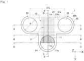
- Fig. 1 is a plan view showing an example of a microfluidic device 1 for use in the drug evaluation method.
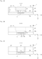
- Fig. 2A is a sectional view of the microfluidic device 1 taken along a line A-A shown in Fig. 1 .
- Fig. 2B is a sectional view of the microfluidic device 1 taken along a line B-B shown in Fig. 1 .
- Fig. 2C is a sectional view of the microfluidic device 1 taken along a line C-C shown in Fig. 1 .
- Fig. 2D is a sectional view of the microfluidic device 1 taken along a line D-D shown in Fig. 1 .
- Fig. 2E is a sectional view of the microfluidic device 1 taken along a line E-E shown in Fig. 1 .
- the microfluidic device 1 is formed by stacking a second substrate 20 on a first substrate 10 in such a manner that one principal surface 20a of the second substrate 20 partially comes into contact with one principal surface 10a of the first substrate 10 and bonding them together.
- the principal surface refers to one of surfaces constituting the substrate 10 or 20 and having a much larger area than other surfaces.
- the substrate 10 or 20 has two principal surfaces, and these two principal surfaces are opposed to each other.
- the principal surface 10a of the first substrate 10 has a plurality of grooves 11a (which will be described later in detail). Further, the principal surface 20a of the second substrate 20 has a recess 21a (which will be described later in detail). The other principal surface 20b of the second substrate 20 is located on the opposite side from the first substrate 10 and has first to third ports 22 to 24 (which will be described later).
- an XYZ coordinate system is referenced as appropriate in which, in a state where the first substrate 10 and the second substrate 20 are bonded together, a plane parallel to the principal surfaces 10a and 10b of the first substrate 10 and the principal surfaces 20a and 20b of the second substrate 20 is defined as an XY plane and a direction orthogonal to the XY plane is defined as a Z direction.
- the direction is described with a positive or negative sign, such as "+X direction” or "-X direction”.
- the direction is simply described as "X direction”. Namely, in a case where a direction is simply described as "X direction” herein, both "+X direction” and "-X direction” are included.
- X direction a direction that is simply described as "X direction” herein, both "+X direction” and "-X direction” are included.
- Y direction and a Z direction the microfluidic device 1 is usually used in such a manner that the Z direction corresponds to a vertical direction, and the -Z direction corresponds to an upward direction.
- first substrate 10 and the second substrate 20 has principal surfaces that are the same in shape.
- the first substrate 10 and the second substrate 20 have an almost T-shape when viewed from the Z direction.
- the thickness of the second substrate 20 is larger than that of the first substrate 10.
- the thickness of the first substrate 10 is, for example, 0.1 to 1 mm, and the thickness of the second substrate 20 is, for example, 3 to 10 mm.
- the principal surface 10a of the first substrate 10 includes the grooves 11a.
- the grooves 11a are formed in the principal surface 10a so as to extend in the Y direction.
- the grooves 11a are formed to be arranged side by side in the X direction.
- the grooves 11a function as a secondary flow path 11 sandwiched between both of the substrates 10 and 20.
- the number of the grooves 11a is, for example, 10 to 1000. In Figs. 1 to 3 , only 8 grooves 11a are shown for the purpose of illustration.
- Each of the grooves 11a has a slit shape that extends in the Y direction so as to have constant width and depth.
- Each of the grooves 11a has a rectangular sectional shape.
- the sectional shape of each of the grooves 11a is not limited to a rectangular shape, and may be a trapezoidal or semi-elliptical shape such that the width decreases toward the groove bottom.
- Each of the grooves 11a has a width 11W (see Fig. 2B ) of, for example, 5 to 100 ⁇ m in the X direction. In the present embodiment, the width 11W is 50 ⁇ m.
- the width 11W of each of the grooves 11a is a width at an opening that is open to the principal surface 10a.
- a space 11S (see Fig. 2B ) between the adjacent grooves 11a is, for example, one to two times the width 11W. In the present embodiment, the space 11S is 50 ⁇ m.
- Each of the grooves 11a has a depth 11H (see Fig. 2B ) of, for example, 50 to 150 ⁇ m. In the present embodiment, the depth 11H is 50 ⁇ m.
- Each of the grooves 11a has a length 11L (see Fig. 2E ) of, for example, 4 to 20 mm. In the present embodiment, the length 11L is 6 mm.
- the principal surface 20a of the second substrate 20 includes the recess 21a.
- the recess 21a is formed in the principal surface 20a so as to extend in the X direction.
- the recess 21a functions as a hollow main flow path 21 sandwiched between both of the substrates 10 and 20.
- the recess 21a has a slit shape that extends in the X direction so as to have constant width and depth.
- the recess 21a has a rectangular sectional shape.
- the recess 21a has a width 21W (see Fig. 2D ) of, for example, 1 to 10 mm in the Y direction.
- the recess 21a has a depth 21H (see Fig. 2D ) of, for example, 0.1 to 5 mm.
- the recess 21a has a length 21L (see Fig. 1 ) of, for example, 4 to 40 mm.
- the main flow path 21 is located in a first XY plane and the secondary flow path 11 is located in a second XY plane different from the first XY plane when the first substrate 10 and the second substrate 20 are bonded together. That is, the secondary flow path 11 is adjacent to the main flow path 21 in the Z direction.
- the first port 22 is connected to the -X direction-side end of the recess 21a, and is formed to extend from the principal surface 20a toward the principal surface 20b of the second substrate 20 and to penetrate the second substrate 20.
- the second port 23 is connected to the +X direction-side end of the recess 21a, and is formed to extend from the principal surface 20a toward the principal surface 20b of the second substrate 20 and to penetrate the second substrate 20.
- the third port 24 is formed in a position independent from the recess 21a to extend from the principal surface 20a toward the principal surface 20b of the second substrate 20 and to penetrate the second substrate 20.
- the third port 24 is formed in a position opposed to one ends 11b of the grooves 11a formed in the first substrate 10 in a state where the first substrate 10 and the second substrate 20 are bonded together. This allows the third port 24 to be connected to the one ends 11b of the grooves 11a when the first substrate 10 and the second substrate 20 are bonded together.
- the first port 22, the second port 23, and the third port 24 are all cylindrical hollows extending in the Z direction.
- the first port 22, the second port 23, and the third port 24 are all the same in diameter d (see Fig. 1 ), and the diameter d is, for example, 1 to 10 mm. It should be noted that it is not necessary for the first port 22, the second port 23, and the third port 24 to have the same diameter d.
- the first port 22, the second port 23, and the third port 24 are all the same in height h (see Fig. 2A ), and the height h is, for example, 3 to 10 mm.
- the distance between the centerline of the main flow path 21 (recess 21a) and the center of the third port 24 in the Y direction is, for example, 3 to 10 mm (see Fig. 2E ).
- the first port 22 and the second port 23 are connected through the main flow path 21. That is, the main flow path 21 can also be said to have the first port 22 and the second port 23 which are connected to the main flow path 21 and extend toward the principal surface 20b.
- the first port 22 and the second port 23 have at least one purpose selected from the purpose of supplying a liquid to the microfluidic device 1 and the purpose of discharging a liquid from the microfluidic device 1.
- the first port 22 and the second port 23 may be used as a supply port and a discharge port, respectively.
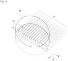
- the grooves 11a are formed in such a manner that the one ends 11b are located on a straight line extending through the center of the third port 24 in the X direction. This allows the one ends 11b of the grooves 11a to communicate with the third port 24. As shown in Fig. 1 , other ends 11c of the grooves 11a are located at a -Y direction-side edge 21b of the recess 21a.
- the grooves 11a have a constant length 11L. Such a constant length 11L of the grooves 11a makes the flow resistance of the grooves 11a constant.
- the grooves 11a extend in the Y direction intersecting the recess 21a and partially overlap the recess 21a when viewed from the Z direction. That is, when viewed from the Z direction, the secondary flow path 11 extends in the Y direction intersecting the main flow path 21 and partially overlaps the main flow path 21.
- an area where the secondary flow path 11 and the main flow path 21 overlap each other when viewed from the Z direction is referred to as an "overlapping area 12".
- the grooves 11a are opposed to the recess 21a in a state where the first substrate 10 and the second substrate 20 are bonded together. This allows the grooves 11a to be open to and communicate with the main flow path 21 in the overlapping area 12.
- the microfluidic device 1 has a culture space 3 therein, and cells can be cultured in the culture space 3.
- the culture space 3 is a space within the main flow path 21 in the overlapping area 12.
- the culture space 3 is opposed to a contact surface 3a (see Fig. 2A ) where the secondary flow path 11 is in contact with the main flow path 21 in the overlapping area 12.
- a contact surface 3a see Fig. 2A
- cells introduced into the main flow path 21 adhere to the bottom surface of the culture space 3, specifically the contact surface 3a, more specifically the principal surface 10a of the first substrate 10 in the overlapping area 12. At this time, the cells adhere onto the secondary flow path 11 so as to cover the grooves 11a.
- the third port 24 is connected to the secondary flow path 11. That is, the secondary flow path 11 can also be said to have the third port 24 connected to the secondary flow path 11 and extending toward the principal surface 20b.
- the third port 24 has the purpose of discharging a liquid in the grooves 11a to the outside.
- the third port 24 may be used as a collection port to collect a liquid in the grooves 11a.
- the microfluidic device 1 has the culture space 3 therein, is capable of culturing cells in the culture space 3, and includes the main flow path 21 and the secondary flow path 11.
- the main flow path 21 extends in the XY plane.
- the secondary flow path 11 is adjacent to the main flow path 21 in a direction (Z direction) perpendicular to the XY plane, extends in a direction intersecting the main flow path 21 when viewed from a direction (Z direction) perpendicular to the XY plane, and partially overlaps the main flow path 21.
- the secondary flow path 11 has the grooves 11a that are open to and communicate with the main flow path 21 in the overlapping area 12 where the secondary flow path 11 overlaps the main flow path 21.
- the culture space 3 is a space within the main flow path 21, the space being opposed to the contact surface 3a where the secondary flow path 11 is in contact with the main flow path 21 in the overlapping area 12 where the secondary flow path 11 overlaps the main flow path 21.
- the contact surface 3a preferably has cell adhesiveness.
- Cell adhesiveness means the property of a surface having a chemical bond as a scaffold for cell adhesion or the property of a surface coatable with an ECM component (such as collagen, gelatin, or laminin), for example, a surface having a functional group such as a hydroxyl group or a carboxy group.
- ECM component such as collagen, gelatin, or laminin
- the width 21W of the main flow path 21 is larger than a cell to be cultured and the width 11W of each of the grooves 11a is smaller than the cell to be cultured.
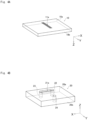
- Fig. 4A is a perspective view of the first substrate 10 before bonding when viewed from the principal surface 10a side
- Fig. 4B is a perspective view of the second substrate 20 before bonding when viewed from the principal surface 20a side.
- a material used to form the substrates 10 and 20 is preferably a substantially non-porous material.
- the "substantially non-porous" herein refers to a state where the apparent surface area of the substrate is approximate to the actual surface area.
- Examples of a material to form such a non-porous material include an inorganic material such as glass or silicon and a resin material such as polymethyl methacrylate (PMMA), polycarbonate (PC), cycloolefin copolymer (COC), cycloolefin polymer (COP), polystyrene (PS), or silicone. It should be noted that these resin materials may be used in combination of two or more of them.
- the material used to form the first substrate 10 and the material used to form the second substrate 20 may be different.
- the shape of the substrates in the present embodiment will be described.
- a substrate is used which has principal surfaces having the same shape.
- the thickness of the second substrate 20 is larger than that of the first substrate 10.
- the first substrate 10 and the second substrate 20 may be different in the shape of principal surfaces.
- the lengthwise dimension and widthwise dimension of principal surface of the first substrate 10 may be larger than those of principal surface of the second substrate 20, or the lengthwise dimension and widthwise dimension of principal surface of the second substrate 20 may be larger than those of principal surface of the first substrate 10.
- the thickness of the second substrate 20 may be the same as that of the first substrate 10, or the thickness of the second substrate 20 may be smaller than that of the first substrate 10.
- the principal surface 10a of the first substrate 10 has the grooves 11a.
- the grooves 11a are formed by, for example, a combination of a photolithographic process and an etching process, nanoimprinting, laser processing, injection molding, or milling.
- the principal surface 20a of the second substrate 20 has the recess 21a.
- the other principal surface 20b of the second substrate 20 has openings as the first port 22, the second port 23, and the third port 24.
- a means such as injection molding or cutting work may be used, but an optimum means may be selected depending on the material forming the substrate.
- a resin material such as polymethyl methacrylate (PMMA), polycarbonate (PC), cycloolefin copolymer (COC), cycloolefin polymer (COP), polystyrene (PS), silicone, or acrylic
- recesses can easily be formed by injection molding.
- the principal surface 10a of the produced first substrate 10 and the principal surface 20a of the produced second substrate 20 are bonded together.
- a bonding method described below does not require formation of a thin film as an adhesive on the substrate and is performed in the following procedure.
- the bonding surfaces (10a, 20a) of both of the substrates are subjected to surface activation treatment.
- a method of the surface activation treatment a method including irradiation with ultraviolet rays or a method including contact with plasma gas can be used.
- the method including irradiation with ultraviolet rays is performed by, for example, irradiating the principal surface 20a of the second substrate 20 and the principal surface 10a of the first substrate 10 with vacuum ultraviolet rays having a wavelength of 200 nm or less emitted from an ultraviolet light source such as a xenon excimer lamp to emit light having a wavelength of 172 nm.
- an ultraviolet light source such as a xenon excimer lamp to emit light having a wavelength of 172 nm.
- a low-pressure mercury lamp having an emission line at 185 nm or a deuterium lamp having an emission line in a wavelength range of 120 to 200 nm can suitably be used.
- the irradiance of the vacuum ultraviolet rays is, for example, 10 to 500 mW/cm 2 .
- An irradiation time is appropriately set depending on the type of resin used, and is, for example, 5 to 6 seconds.
- the method including contact with plasma gas is performed by generating plasma of a process gas containing nitrogen gas or argon gas as a main component and containing 0.01 to 5 vol% of oxygen gas by atmospheric-pressure plasma and bringing the plasma into contact with the principal surface 20a of the second substrate 20 and the principal surface 10a of the first substrate 10. It is also possible to use a mixed gas of nitrogen gas and clean dry air (CDA).
- CDA clean dry air
- the time of contact with the plasma gas is, for example, 5 to 100 seconds.
- a bonding step is performed in which the first substrate 10 and the second substrate 20 are stacked in such a manner that the bonding surfaces (10a, 20a) of both of the substrates subjected to surface activation treatment are in contact with each other, and both of the substrates are bonded together by pressing using a press machine.
- the bonding step should be performed within a predetermined time, for example, within 10 minutes after the completion of an ultraviolet irradiation step in order to maintain the surface activation state.
- the bonding step is performed in a thermal environment to achieve tight bonding.
- bonding conditions such as heating temperature and pressing force are set depending on the constituent material of the first substrate 10 and the constituent material of the second substrate 20.
- the temperature during pressing is, for example, 40 to 130°C
- the pressing force for bonding is, for example, 0.1 to 10 MPa.
- a substrate obtained by bonding the first substrate 10 and the second substrate 20 together may further be heated for a predetermined time after pressurization for a predetermined time. Even when a portion achieving a satisfactory bonding state and a portion not achieving a satisfactory bonding state are mixed at a bonded interface between the stacked substrates after pressurization, a desired bonding state can be achieved in the portion not achieving a satisfactory bonding state by heating the bonded substrate after pressurization.
- the temperature of the bonded substrate may be increased to and maintained at a predetermined temperature until a desired bonding state is achieved.
- the predetermined temperature is a temperature at which deformation of the bonded substrate does not occur.
- a heating temperature is, for example, 40 to 130°C and a heating time is, for example, 60 to 600 seconds.
- the microfluidic device 1 in which the second substrate 20 is bonded onto the principal surface 10a of the first substrate 10 is produced through a cooling step.
- microfluidic device 1 used in the drug evaluation method according to the present invention to collect bile is not limited to the above-described microfluidic device 1.
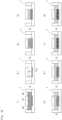
- Fig. 5 is a schematic diagram for illustrating the drug evaluation method using the microfluidic device 1, in which plan views are shown on the left side and sectional views are shown on the right side. It should be noted that in the plan views, the grooves 11a are indicated by hatched lines for explanatory convenience.
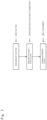
- Fig. 6 is an overall flow diagram of the drug evaluation method.
- Fig. 7 is a flow diagram of the drug evaluation method.
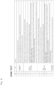
- Fig. 8 is a flow diagram of a pharmacokinetic (AMDE) study.
- AMDE pharmacokinetic
- a hepatic function evaluation step shown in Fig. 7 and Fig. 8 is performed.
- the hepatic function evaluation step is performed to discard the microfluidic device 1 whose hepatic function is below a certain level to perform a drug evaluation described later using the microfluidic device 1 whose haptic function is at or above the certain level.
- the hepatic function evaluation step is performed through the following steps. First, a reference drug is added and supplied to a culture medium to be perfused (Step 104 shown in Fig. 8 ). Then, the reference drug is taken into the hepatocytes 9, and bile is excreted into the bile collection flow path (grooves 11a) (Step 105 shown in Fig. 8 ). Then, the culture medium after perfusion and a liquid containing the excreted bile are collected (Step 106 shown in Fig. 8 ).
- the reference drug, a chemical structure after metabolism, and a chemical structure after bile conjugation in the collected bile and their concentrations are analyzed by, for example, a liquid chromatography mass spectrometer (Step 107 shown in Fig. 8 ).
- the reference drug, a chemical structure after metabolism, and a chemical structure after bile conjugation in the collected culture medium and their concentrations are analyzed by, for example, a liquid chromatography mass spectrometer (Step 108 shown in Fig. 8 ).
- the metabolic capability and excretion capability of the microfluidic device 1 are measured (Step 109 shown in Fig. 8 ).
- a cell culture state may also be observed with a microscope as a reference.
- a drug evaluation step shown in Fig. 7 and Fig. 8 is performed.
- a physiologically active substance and a drug to be evaluated are charged through the supply port into the main flow path 21 in which the hepatocytes 9 that can excrete bile are cultured (the step 3 in the present invention, Step 110 shown in Fig. 8 ).
- the drug is taken into the hepatocytes 9, and bile is excreted into the bile collection flow path (grooves 11a) (Step 111 shown in Fig. 8 ).
- the culture medium after perfusion and a liquid containing the excreted bile are collected (Step 112 shown in Fig. 8 ).
- bile 90 excreted from the tiny bile ducts flows into the grooves 11a of the secondary flow path 11 and is collected through the collection port (e.g., the third port 24) (the step 4 in the present invention). Since most or all of the space above the secondary flow path 11 is filled with the hepatocytes 9 at this time, it is possible to almost completely or completely prevent the culture medium in the main flow path 21 from flowing into the secondary flow path 11.
- the bile 90 can be collected while the hepatocytes 9 are continued to be cultured. Therefore, the bile 90 can be collected not at a specific point in time but continuously in an environment close to in vivo conditions.
- the step 4 of collecting the bile 90 is preferably performed continuously for one day (24 hours) or more.
- the phrase "the step 4 of collecting the bile 90 is performed continuously for one day or more" herein refers not only to continuously collecting the bile 90 for one day or more but also to collecting the bile 90 two or more times for a time period of one day or more, such as a case where after the first collection of the bile 90, the second collection of the bile 90 is performed after a lapse of a predetermined number of days from the first collection.
- the reason why the bile 90 is continuously collected over a relatively long time span is to understand damage to the hepatocytes 9 due to long-term exposure to the drug.
- the bile 90 collected through the collection port is analyzed (the step 5 in the present invention).
- the step 5 is performed by, for example, gas chromatography or liquid chromatography.
- the reference drug, a chemical structure after metabolism, and a chemical structure after bile conjugation in the collected bile and their concentrations are analyzed by, for example, a liquid chromatography mass spectrometer (Step 113 shown in Fig. 8 ).
- the reference drug, a chemical structure after metabolism, and a chemical structure after bile conjugation in the collected culture medium and their concentrations are analyzed by, for example, a liquid chromatography mass spectrometer (Step 114 shown in Fig. 8 ).
- the step 5 is preferably performed at at least two time points temporally independent from each other.
- the collected bile 90 is preferably analyzed at at least two time points temporally independent from each other.
- the bile 90 is collected and analyzed every other day or every other week.
- pharmacokinetics are evaluated from an analytical result obtained in the step 5 (the step 6 in the present invention). Specifically, pharmacokinetics (metabolic rate, metabolic mode, bile acid conjugation, excretion concentration) of the drug are calculated and compared with the references obtained by the above-described hepatic function evaluation to evaluate the pharmacokinetics (Step 115 shown in Fig. 8 ). Further, long-term evaluation of pharmacokinetics can be performed by repeated administration or long-term supply of the drug (Step 116 shown in Fig. 8 ).
- the behavior of a drug in a living body is mainly considered from the time-shift of blood level of the drug.
- Elements used therefor are called pharmacokinetic parameters.
- the pharmacokinetic parameters include maximum drug concentration (Cmax), minimum drug concentration (Cmin), time to maximum concentration (Tmax), blood concentration half-life (T1/2), and area under the blood concentration-time curve (AUC).
- the presence of the drug can be confirmed by infrared spectroscopic analysis. Further, the state of chemical structure of a drug compound excreted together with bile is evaluated. Collected bile is analyzed by a GC/MS (gas chromatography mass spectrometer) or a LC/MS/MS (liquid chromatography mass spectrometer) to identify the structure of the drug compound to determine whether the structure has changed and to determine, if the structure has changed, how the structure has changed.
- a GC/MS gas chromatography mass spectrometer
- LC/MS/MS liquid chromatography mass spectrometer
- the changes of the chemical structure refer to bile acid conjugation, modification or replacement with a functional group, and cleavage of a bond.
- the change of the chemical structure described in the above a) is not limited to one type.
- the chemical structure of the drug compound changes at various sites so that various derivative compounds are produced.
- bile acid is also a mixture of a plurality kinds of substances. If the change of the composition (the types and concentrations of the substances) of bile acid can be analyzed and linked to the physiological activity of an existing drug, the physiological activity of the unevaluated drug can be predicted by determining the composition of bile acid.
- the balance of the drug to be excreted into bile can be estimated.
- the efficacy, pharmacokinetics, and toxicity of the drug can be evaluated more multidirectionally by a culture test system.
- Bile excretion function is not constant over a long period of time.
- the function of hepatocytes changes due to the effects of the drug (back action of efficacy, dependence, intoxicated state). The change may occur in several hours (acute) or for several days (chronic). Further, a living body is influenced by a biorhythm.
- bile excretion function changes depending on the culture state of cells (e.g., the degree of maturation of function, the length of time from the start of culture).
- the efficacy or toxicity of the drug can also be evaluated.
- the effect of the drug on a bile excretion rate can be evaluated by monitoring the bile excretion rate.
- a drug that reduces the bile excretion rate inhibits bile excretion (cholestasis).
- the concentration of the drug in the liver increases, the drug becomes toxic.
- a drug that increases the bile excretion rate promotes bile excretion, and therefore the concentration of the drug in the liver reduces so that the efficacy of the drug appears.
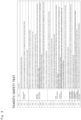
- Fig 9 is a flow diagram of a toxicity/safety test of a drug.
- a preliminary culture step is performed.
- Steps 201 to 203 are the same as Steps 101 to 103 shown in Fig. 8 , and therefore the description thereof will not be repeated.
- Step 204 to 209 are the same as Steps 104 to 109 shown in Fig. 8 , and therefore the description thereof will not be repeated.
- Step 210 a cell culture state is observed with a microscope which is used as a reference.
- Steps 211 to 216 are the same as Steps 110 to 115 shown in Fig. 8 , and therefore the description thereof will not be repeated.
- Step 217 biomarkers (damage marker, inflammatory marker, inflammation-inducing substance) in the culture medium and the bile are measured.
- Step 218 a cell culture state is observed to observe the state of cell damage.
- Step 219 long-term evaluation of pharmacokinetics can be performed by repeated administration or long-term supply of the drug.
- Step 220 the bile excretion rate-reducing effect of the drug may be evaluated.
- the hepatocytes 9 may be collected from the microfluidic device 1 to measure the contents and amounts of the biomarkers (damage marker, inflammatory marker, inflammation-inducing substance) on the surfaces of the cells and in the cells.
- the biomarkers damage marker, inflammatory marker, inflammation-inducing substance
- mRNA may be obtained from the hepatocytes 9 collected from the microfluidic device 1 to measure gene expression.
- toxicity of the drug can also be evaluated by directly observing the cells as in the case of Step 218.
- the amount of reduction in the number of bile ducts formed from a normal state, the amount of increase in the number of dead cells, and the proper functioning of paths for bile excretion can quantitatively be evaluated by determining the presence or absence of a fluorescent probe accumulated in the cells.
- Fig. 10 is a sectional view for illustrating another usage example of the microfluidic device 1.
- the main flow path 21 is filled with a solution for forming a gel.
- the solution for forming a gel filled in the grooves 11a is left and gelatinized.
- a gel 13 may be, for example, a collagen gel.
- a collagen gel is a gel constituted from collagen fibers. Filling the grooves 11a with the gel 13 makes it possible to culture cells in the culture space 3 even when the cells are smaller than the width 11W of each of the grooves 11a.
- hepatocytes are inoculated. Then, 4) the hepatocytes are fixed to the culture space 3 (30 minutes to 1 hour). Specifically, the hepatocytes are allowed to adhere to the contact surface 3a as the bottom surface of the culture space 3.
- the first port 22 and the second port 23 are also filled with a culture medium to grow the hepatocytes to obtain hepatic tissue (several days).
- bile canaliculi are formed in the hepatic tissue. Then, 7) the bile canaliculi open to the grooves 11a. Then, 8) bile is discharged into the grooves 11a.
- the gel 13 may be removed after the cells grow to a size such that they do not fall into the grooves 11a.
- the gel 13 can be removed by any appropriate method such as spontaneous decomposition, thermal dissolution, or enzymatic decomposition. Even after the gel 13 is removed, membranes or the like of the cells cultured in the culture space 3 are supported by the principal surface 10a between the adjacent grooves 11a, and therefore the form of the cells is maintained.
Landscapes
- Health & Medical Sciences (AREA)
- Life Sciences & Earth Sciences (AREA)
- Engineering & Computer Science (AREA)
- Biomedical Technology (AREA)
- Chemical & Material Sciences (AREA)
- Immunology (AREA)
- Biotechnology (AREA)
- Cell Biology (AREA)
- Bioinformatics & Cheminformatics (AREA)
- Molecular Biology (AREA)
- Hematology (AREA)
- Urology & Nephrology (AREA)
- Microbiology (AREA)
- Biochemistry (AREA)
- Toxicology (AREA)
- General Health & Medical Sciences (AREA)
- Organic Chemistry (AREA)
- Food Science & Technology (AREA)
- Zoology (AREA)
- Tropical Medicine & Parasitology (AREA)
- Wood Science & Technology (AREA)
- Genetics & Genomics (AREA)
- Gastroenterology & Hepatology (AREA)
- Pathology (AREA)
- Medicinal Chemistry (AREA)
- Physics & Mathematics (AREA)
- Analytical Chemistry (AREA)
- General Physics & Mathematics (AREA)
- General Engineering & Computer Science (AREA)
- Apparatus Associated With Microorganisms And Enzymes (AREA)
- Measuring Or Testing Involving Enzymes Or Micro-Organisms (AREA)
- Micro-Organisms Or Cultivation Processes Thereof (AREA)
Abstract
Description
- The present invention relates to a drug evaluation method.
- In the liver, drugs or other compounds are absorbed into and metabolized by hepatocytes. Hepatic metabolites are excreted into bile canaliculi, reach the gallbladder, and are then discharged from the body.
- There are some conventionally-known methods for collecting and analyzing bile secreted from hepatocytes. For example, a method is known in which hepatocytes are cultured on a membrane by sandwich culture method to form tiny bile ducts, and bile secreted from the tiny bile ducts is collected (
Patent Document 1 mentioned below). Further, for example, a method is known in which bile is collected from a test animal such as a mouse by directly discharging bile from the body through a catheter inserted into the biliary tract. - Patent Document 1:
JP-A-2013-17411 - In the case of sandwich culture method, there is a problem that the life-span of hepatocytes is short (e.g., about 10 days). Further, since sandwich culture method is performed in a state of biliary obstruction where bile is not excreted, intercellular connections need to be broken to collect bile, and therefore continuous analysis (analysis in a state where cells are alive) cannot be performed. That is, sandwich culture method cannot simulate continuous excretion of bile from the human liver. Specifically, sandwich culture method can evaluate bile at a specific point in time but cannot evaluate liver damage caused by administration of a drug for a long period of time.
- Animal testing has a problem that drug response varies among individuals of each species, and requires an implantation technique of high difficulty level and know-how to handle animals. First of all, since animals are used, it is not known whether a drug shows the same behavior as when administered to humans.
- For these reasons, there is a need for preclinical confirmation of drug safety by continuously evaluating drug efficacy, long-term side effects caused by drug administration, and pharmacokinetics in an environment close to in vivo conditions for a predetermined period of time.
- In light of the above problems, it is an object of the present invention to provide a drug evaluation method capable of evaluating a drug by collecting bile not at a specific point in time but continuously in an environment close to in vivo conditions.
- The present invention is directed to a drug evaluation method including:
- a
step 1 in which hepatocytes and a culture medium are introduced into a microfluidic device; - a
step 2 in which after thestep 1, the hepatocytes are cultured until bile can be excreted therefrom; - a
step 3 in which after thestep 2, a drug is administered to the hepatocytes; and - a
step 4 in which after thestep 3, the bile excreted from the hepatocytes is collected. - Such a configuration makes it possible to collect bile excreted from hepatocytes while continuing to culture the hepatocytes, and therefore bile can be collected not at a specific point in time but continuously in an environment close to in vivo conditions.
- The drug evaluation method according to the present invention may include a
step 5 in which the bile collected in thestep 4 is analyzed and astep 6 in which pharmacokinetics are evaluated from an analytical result obtained in thestep 5. - Such a configuration makes it possible to continuously evaluate pharmacokinetics for a long period of time.
- In the drug evaluation method according to the present invention, the
step 6 may be a step of evaluating at least one selected from a structure of the drug excreted into bile, a component composition of the drug excreted into bile, a rate parameter of biliary excretion, continuous temporal changes in excretion rate and excretion amount, and a continuous temporal change in metabolism/excretion. - In the drug evaluation method according to the present invention, the
step 4 may continuously be performed for one day or more. - In the drug evaluation method according to the present invention, the
step 5 may be performed at at least two time points temporally independent from each other. - Such configurations make it possible, when hepatocytes are exposed to a drug for a long period of time, to understand damage to the hepatocytes.
-
-
Fig. 1 is a plan view of a microfluidic device according to an embodiment of the present invention. -
Fig. 2A is a sectional view of the microfluidic device taken along a line A-A shown inFig. 1 . -
Fig. 2B is a sectional view of the microfluidic device taken along a line B-B shown inFig. 1 . -
Fig. 2C is a sectional view of the microfluidic device taken along a line C-C shown inFig. 1 . -
Fig. 2D is a sectional view of the microfluidic device taken along a line D-D shown inFig. 1 . -
Fig. 2E is a sectional view of the microfluidic device taken along a line E-E shown inFig. 1 . -
Fig. 3 is a perspective view of a third port and its vicinity. -
Fig. 4A is a perspective view of a first substrate. -
Fig. 4B is a perspective view of a second substrate. -
Fig. 5 is a schematic view for illustrating a drug evaluation method using the microfluidic device. -
Fig. 6 is an overall flow diagram of the drug evaluation method. -
Fig. 7 is a flow diagram of the drug evaluation method. -
Fig. 8 is a flow diagram of a pharmacokinetic (AMDE) study. -
Fig 9 is a flow diagram of a toxicity/safety test of a drug. -
Fig. 10 is a sectional view for illustrating another usage example of the microfluidic device. - A drug evaluation method according to the present invention will be described with reference to the drawings. It should be noted that the drawings disclosed herein merely show schematic illustrations. Namely, the dimensional ratios on the drawings do not necessarily reflect the actual dimensional ratios, and the dimensional ratios are not necessarily the same between the drawings.
-
Fig. 1 is a plan view showing an example of amicrofluidic device 1 for use in the drug evaluation method.Fig. 2A is a sectional view of themicrofluidic device 1 taken along a line A-A shown inFig. 1 .Fig. 2B is a sectional view of themicrofluidic device 1 taken along a line B-B shown inFig. 1 .Fig. 2C is a sectional view of themicrofluidic device 1 taken along a line C-C shown inFig. 1 .Fig. 2D is a sectional view of themicrofluidic device 1 taken along a line D-D shown inFig. 1 .Fig. 2E is a sectional view of themicrofluidic device 1 taken along a line E-E shown inFig. 1 . - The
microfluidic device 1 is formed by stacking asecond substrate 20 on afirst substrate 10 in such a manner that oneprincipal surface 20a of thesecond substrate 20 partially comes into contact with oneprincipal surface 10a of thefirst substrate 10 and bonding them together. The principal surface refers to one of surfaces constituting thesubstrate substrate - The
principal surface 10a of thefirst substrate 10 has a plurality ofgrooves 11a (which will be described later in detail). Further, theprincipal surface 20a of thesecond substrate 20 has arecess 21a (which will be described later in detail). The otherprincipal surface 20b of thesecond substrate 20 is located on the opposite side from thefirst substrate 10 and has first tothird ports 22 to 24 (which will be described later). - In the following description, an XYZ coordinate system is referenced as appropriate in which, in a state where the
first substrate 10 and thesecond substrate 20 are bonded together, a plane parallel to theprincipal surfaces first substrate 10 and theprincipal surfaces second substrate 20 is defined as an XY plane and a direction orthogonal to the XY plane is defined as a Z direction. - When it is necessary to make a distinction between positive and negative to express a direction herein, the direction is described with a positive or negative sign, such as "+X direction" or "-X direction". When it is not necessary to make a distinction between positive and negative to express a direction, the direction is simply described as "X direction". Namely, in a case where a direction is simply described as "X direction" herein, both "+X direction" and "-X direction" are included. The same applies to a Y direction and a Z direction. It should be noted that the
microfluidic device 1 is usually used in such a manner that the Z direction corresponds to a vertical direction, and the -Z direction corresponds to an upward direction. - Each of the
first substrate 10 and thesecond substrate 20 has principal surfaces that are the same in shape. In themicrofluidic device 1 of the present embodiment, thefirst substrate 10 and thesecond substrate 20 have an almost T-shape when viewed from the Z direction. The thickness of thesecond substrate 20 is larger than that of thefirst substrate 10. The thickness of thefirst substrate 10 is, for example, 0.1 to 1 mm, and the thickness of thesecond substrate 20 is, for example, 3 to 10 mm. - The
principal surface 10a of thefirst substrate 10 includes thegrooves 11a. Thegrooves 11a are formed in theprincipal surface 10a so as to extend in the Y direction. Thegrooves 11a are formed to be arranged side by side in the X direction. When thefirst substrate 10 and thesecond substrate 20 are bonded together, thegrooves 11a function as asecondary flow path 11 sandwiched between both of thesubstrates grooves 11a is, for example, 10 to 1000. InFigs. 1 to 3 , only 8grooves 11a are shown for the purpose of illustration. - Each of the
grooves 11a has a slit shape that extends in the Y direction so as to have constant width and depth. Each of thegrooves 11a has a rectangular sectional shape. However, the sectional shape of each of thegrooves 11a is not limited to a rectangular shape, and may be a trapezoidal or semi-elliptical shape such that the width decreases toward the groove bottom. - Each of the
grooves 11a has awidth 11W (seeFig. 2B ) of, for example, 5 to 100 µm in the X direction. In the present embodiment, thewidth 11W is 50 µm. Thewidth 11W of each of thegrooves 11a is a width at an opening that is open to theprincipal surface 10a. Aspace 11S (seeFig. 2B ) between theadjacent grooves 11a is, for example, one to two times thewidth 11W. In the present embodiment, thespace 11S is 50 µm. Each of thegrooves 11a has a depth 11H (seeFig. 2B ) of, for example, 50 to 150 µm. In the present embodiment, the depth 11H is 50 µm. Each of thegrooves 11a has alength 11L (seeFig. 2E ) of, for example, 4 to 20 mm. In the present embodiment, thelength 11L is 6 mm. - The
principal surface 20a of thesecond substrate 20 includes therecess 21a. Therecess 21a is formed in theprincipal surface 20a so as to extend in the X direction. When thefirst substrate 10 and thesecond substrate 20 are bonded together, therecess 21a functions as a hollowmain flow path 21 sandwiched between both of thesubstrates - The
recess 21a has a slit shape that extends in the X direction so as to have constant width and depth. Therecess 21a has a rectangular sectional shape. - The
recess 21a has awidth 21W (seeFig. 2D ) of, for example, 1 to 10 mm in the Y direction. Therecess 21a has adepth 21H (seeFig. 2D ) of, for example, 0.1 to 5 mm. Therecess 21a has alength 21L (seeFig. 1 ) of, for example, 4 to 40 mm. - By forming the
grooves 11a in theprincipal surface 10a of thefirst substrate 10 and forming therecess 21a in theprincipal surface 20a of thesecond substrate 20, themain flow path 21 is located in a first XY plane and thesecondary flow path 11 is located in a second XY plane different from the first XY plane when thefirst substrate 10 and thesecond substrate 20 are bonded together. That is, thesecondary flow path 11 is adjacent to themain flow path 21 in the Z direction. - The
first port 22 is connected to the -X direction-side end of therecess 21a, and is formed to extend from theprincipal surface 20a toward theprincipal surface 20b of thesecond substrate 20 and to penetrate thesecond substrate 20. Thesecond port 23 is connected to the +X direction-side end of therecess 21a, and is formed to extend from theprincipal surface 20a toward theprincipal surface 20b of thesecond substrate 20 and to penetrate thesecond substrate 20. - The
third port 24 is formed in a position independent from therecess 21a to extend from theprincipal surface 20a toward theprincipal surface 20b of thesecond substrate 20 and to penetrate thesecond substrate 20. Thethird port 24 is formed in a position opposed to one ends 11b of thegrooves 11a formed in thefirst substrate 10 in a state where thefirst substrate 10 and thesecond substrate 20 are bonded together. This allows thethird port 24 to be connected to the one ends 11b of thegrooves 11a when thefirst substrate 10 and thesecond substrate 20 are bonded together. - The
first port 22, thesecond port 23, and thethird port 24 are all cylindrical hollows extending in the Z direction. In themicrofluidic device 1 of the present embodiment, thefirst port 22, thesecond port 23, and thethird port 24 are all the same in diameter d (seeFig. 1 ), and the diameter d is, for example, 1 to 10 mm. It should be noted that it is not necessary for thefirst port 22, thesecond port 23, and thethird port 24 to have the same diameter d. Thefirst port 22, thesecond port 23, and thethird port 24 are all the same in height h (seeFig. 2A ), and the height h is, for example, 3 to 10 mm. The distance between the centerline of the main flow path 21 (recess 21a) and the center of thethird port 24 in the Y direction is, for example, 3 to 10 mm (seeFig. 2E ). - The
first port 22 and thesecond port 23 are connected through themain flow path 21. That is, themain flow path 21 can also be said to have thefirst port 22 and thesecond port 23 which are connected to themain flow path 21 and extend toward theprincipal surface 20b. - The
first port 22 and thesecond port 23 have at least one purpose selected from the purpose of supplying a liquid to themicrofluidic device 1 and the purpose of discharging a liquid from themicrofluidic device 1. For example, thefirst port 22 and thesecond port 23 may be used as a supply port and a discharge port, respectively. - As shown in
Fig. 1 andFig. 3 , in a state where thefirst substrate 10 and thesecond substrate 20 are bonded together, thegrooves 11a are formed in such a manner that the one ends 11b are located on a straight line extending through the center of thethird port 24 in the X direction. This allows the one ends 11b of thegrooves 11a to communicate with thethird port 24. As shown inFig. 1 , other ends 11c of thegrooves 11a are located at a -Y direction-side edge 21b of therecess 21a. Thegrooves 11a have aconstant length 11L. Such aconstant length 11L of thegrooves 11a makes the flow resistance of thegrooves 11a constant. - In a state where the
first substrate 10 and thesecond substrate 20 are bonded together, thegrooves 11a extend in the Y direction intersecting therecess 21a and partially overlap therecess 21a when viewed from the Z direction. That is, when viewed from the Z direction, thesecondary flow path 11 extends in the Y direction intersecting themain flow path 21 and partially overlaps themain flow path 21. Here, an area where thesecondary flow path 11 and themain flow path 21 overlap each other when viewed from the Z direction is referred to as an "overlappingarea 12". - The
grooves 11a are opposed to therecess 21a in a state where thefirst substrate 10 and thesecond substrate 20 are bonded together. This allows thegrooves 11a to be open to and communicate with themain flow path 21 in the overlappingarea 12. - The
microfluidic device 1 has aculture space 3 therein, and cells can be cultured in theculture space 3. Theculture space 3 is a space within themain flow path 21 in the overlappingarea 12. Theculture space 3 is opposed to acontact surface 3a (seeFig. 2A ) where thesecondary flow path 11 is in contact with themain flow path 21 in the overlappingarea 12. Although described later in detail, cells introduced into themain flow path 21 adhere to the bottom surface of theculture space 3, specifically thecontact surface 3a, more specifically theprincipal surface 10a of thefirst substrate 10 in the overlappingarea 12. At this time, the cells adhere onto thesecondary flow path 11 so as to cover thegrooves 11a. - The
third port 24 is connected to thesecondary flow path 11. That is, thesecondary flow path 11 can also be said to have thethird port 24 connected to thesecondary flow path 11 and extending toward theprincipal surface 20b. - The
third port 24 has the purpose of discharging a liquid in thegrooves 11a to the outside. For example, thethird port 24 may be used as a collection port to collect a liquid in thegrooves 11a. - As described above, the
microfluidic device 1 according to the present embodiment has theculture space 3 therein, is capable of culturing cells in theculture space 3, and includes themain flow path 21 and thesecondary flow path 11. Themain flow path 21 extends in the XY plane. Thesecondary flow path 11 is adjacent to themain flow path 21 in a direction (Z direction) perpendicular to the XY plane, extends in a direction intersecting themain flow path 21 when viewed from a direction (Z direction) perpendicular to the XY plane, and partially overlaps themain flow path 21. Thesecondary flow path 11 has thegrooves 11a that are open to and communicate with themain flow path 21 in the overlappingarea 12 where thesecondary flow path 11 overlaps themain flow path 21. Theculture space 3 is a space within themain flow path 21, the space being opposed to thecontact surface 3a where thesecondary flow path 11 is in contact with themain flow path 21 in the overlappingarea 12 where thesecondary flow path 11 overlaps themain flow path 21. - In the
microfluidic device 1 according to the present embodiment, thecontact surface 3a preferably has cell adhesiveness. Cell adhesiveness means the property of a surface having a chemical bond as a scaffold for cell adhesion or the property of a surface coatable with an ECM component (such as collagen, gelatin, or laminin), for example, a surface having a functional group such as a hydroxyl group or a carboxy group. - In the
microfluidic device 1 according to the present embodiment, it is preferred that thewidth 21W of themain flow path 21 is larger than a cell to be cultured and thewidth 11W of each of thegrooves 11a is smaller than the cell to be cultured. - Hereinbelow, a method for producing the
microfluidic device 1 will be described in detail. - The
first substrate 10 and thesecond substrate 20 to form themicrofluidic device 1 are prepared.Fig. 4A is a perspective view of thefirst substrate 10 before bonding when viewed from theprincipal surface 10a side, andFig. 4B is a perspective view of thesecond substrate 20 before bonding when viewed from theprincipal surface 20a side. - A material used to form the
substrates first substrate 10 and the material used to form thesecond substrate 20 may be different. - The shape of the substrates in the present embodiment will be described. As each of the
first substrate 10 and thesecond substrate 20, a substrate is used which has principal surfaces having the same shape. The thickness of thesecond substrate 20 is larger than that of thefirst substrate 10. However, thefirst substrate 10 and thesecond substrate 20 may be different in the shape of principal surfaces. For example, the lengthwise dimension and widthwise dimension of principal surface of thefirst substrate 10 may be larger than those of principal surface of thesecond substrate 20, or the lengthwise dimension and widthwise dimension of principal surface of thesecond substrate 20 may be larger than those of principal surface of thefirst substrate 10. The thickness of thesecond substrate 20 may be the same as that of thefirst substrate 10, or the thickness of thesecond substrate 20 may be smaller than that of thefirst substrate 10. - The
principal surface 10a of thefirst substrate 10 has thegrooves 11a. Thegrooves 11a are formed by, for example, a combination of a photolithographic process and an etching process, nanoimprinting, laser processing, injection molding, or milling. - The
principal surface 20a of thesecond substrate 20 has therecess 21a. The otherprincipal surface 20b of thesecond substrate 20 has openings as thefirst port 22, thesecond port 23, and thethird port 24. - In order to provide openings and recesses in the
second substrate 20, for example, a means such as injection molding or cutting work may be used, but an optimum means may be selected depending on the material forming the substrate. For example, as described above, when thesecond substrate 20 is formed using a resin material such as polymethyl methacrylate (PMMA), polycarbonate (PC), cycloolefin copolymer (COC), cycloolefin polymer (COP), polystyrene (PS), silicone, or acrylic, recesses can easily be formed by injection molding. - The
principal surface 10a of the producedfirst substrate 10 and theprincipal surface 20a of the producedsecond substrate 20 are bonded together. A bonding method described below does not require formation of a thin film as an adhesive on the substrate and is performed in the following procedure. - First, the bonding surfaces (10a, 20a) of both of the substrates are subjected to surface activation treatment. As a method of the surface activation treatment, a method including irradiation with ultraviolet rays or a method including contact with plasma gas can be used.
- The method including irradiation with ultraviolet rays is performed by, for example, irradiating the
principal surface 20a of thesecond substrate 20 and theprincipal surface 10a of thefirst substrate 10 with vacuum ultraviolet rays having a wavelength of 200 nm or less emitted from an ultraviolet light source such as a xenon excimer lamp to emit light having a wavelength of 172 nm. As another example of the ultraviolet light source, a low-pressure mercury lamp having an emission line at 185 nm or a deuterium lamp having an emission line in a wavelength range of 120 to 200 nm can suitably be used. The irradiance of the vacuum ultraviolet rays is, for example, 10 to 500 mW/cm2. An irradiation time is appropriately set depending on the type of resin used, and is, for example, 5 to 6 seconds. - The method including contact with plasma gas is performed by generating plasma of a process gas containing nitrogen gas or argon gas as a main component and containing 0.01 to 5 vol% of oxygen gas by atmospheric-pressure plasma and bringing the plasma into contact with the
principal surface 20a of thesecond substrate 20 and theprincipal surface 10a of thefirst substrate 10. It is also possible to use a mixed gas of nitrogen gas and clean dry air (CDA). The time of contact with the plasma gas is, for example, 5 to 100 seconds. - Then, a bonding step is performed in which the
first substrate 10 and thesecond substrate 20 are stacked in such a manner that the bonding surfaces (10a, 20a) of both of the substrates subjected to surface activation treatment are in contact with each other, and both of the substrates are bonded together by pressing using a press machine. The bonding step should be performed within a predetermined time, for example, within 10 minutes after the completion of an ultraviolet irradiation step in order to maintain the surface activation state. - If necessary, the bonding step is performed in a thermal environment to achieve tight bonding. In the bonding step, bonding conditions such as heating temperature and pressing force are set depending on the constituent material of the
first substrate 10 and the constituent material of thesecond substrate 20. As for specific conditions, the temperature during pressing is, for example, 40 to 130°C, and the pressing force for bonding is, for example, 0.1 to 10 MPa. - If necessary, a substrate obtained by bonding the
first substrate 10 and thesecond substrate 20 together (hereinafter sometimes referred to as a "bonded substrate") may further be heated for a predetermined time after pressurization for a predetermined time. Even when a portion achieving a satisfactory bonding state and a portion not achieving a satisfactory bonding state are mixed at a bonded interface between the stacked substrates after pressurization, a desired bonding state can be achieved in the portion not achieving a satisfactory bonding state by heating the bonded substrate after pressurization. - After the pressurization of the bonded substrate is maintained for a predetermined time and then stopped, the temperature of the bonded substrate may be increased to and maintained at a predetermined temperature until a desired bonding state is achieved. Here, the predetermined temperature is a temperature at which deformation of the bonded substrate does not occur. For example, a heating temperature is, for example, 40 to 130°C and a heating time is, for example, 60 to 600 seconds.
- Then, the
microfluidic device 1 in which thesecond substrate 20 is bonded onto theprincipal surface 10a of thefirst substrate 10 is produced through a cooling step. - Hereinbelow, the drug evaluation method using the
microfluidic device 1 will be described in detail. However, a microfluidic device used in the drug evaluation method according to the present invention to collect bile is not limited to the above-describedmicrofluidic device 1. -
Fig. 5 is a schematic diagram for illustrating the drug evaluation method using themicrofluidic device 1, in which plan views are shown on the left side and sectional views are shown on the right side. It should be noted that in the plan views, thegrooves 11a are indicated by hatched lines for explanatory convenience.Fig. 6 is an overall flow diagram of the drug evaluation method.Fig. 7 is a flow diagram of the drug evaluation method.Fig. 8 is a flow diagram of a pharmacokinetic (AMDE) study. - (1) First of all, a preliminary culture step shown in
Fig. 7 andFig. 8 is performed. First, as shown inFig. 5(a) andFig. 6 ,hepatocytes 9 and a culture medium (not shown inFig. 5(a) ) are introduced into the microfluidic device 1 (thestep 1 in the present invention). Specifically, as shown inFig. 5(a) , thehepatocytes 9 are introduced through the supply port (e.g., the first port 22) to be inoculated in themain flow path 21. At this time, thehepatocytes 9 are introduced as clusters of cells. The size of each of the clusters of cells is, for example, about 50 to 300 µm.
As shown inFig. 5(b) , the clusters of cells introduced into themain flow path 21 adhere to the bottom surface (contact surface 3a) of themain flow path 21. By setting thewidth 11W of each of thegrooves 11a to be smaller than each of the clusters of cells, the clusters of cells adhere onto thesecondary flow path 11. - (2) Then, as shown in
Fig. 5(c) , the culture medium is injected through the supply port. The culture medium is perfused into themain flow path 21 by collecting it through the discharge port (e.g., the second port 23) to grow thehepatocytes 9. Thehepatocytes 9 grow so that most or all of a space above thesecondary flow path 11 is filled with them. As thehepatocytes 9 grow, tiny bile ducts (bile canaliculi) are formed in thehepatocytes 9. Until thehepatocytes 9 can excrete bile, culture of thehepatocytes 9 is continued by perfusing the culture medium (thestep 2 in the present invention,Step 101 shown inFig. 8 ). Then, bile duct formation and barrier formation are confirmed using a fluorescent pigment tracer or TEER (Step 102 shown inFig. 8 ). Further, bile continuously excreted from thehepatocytes 9 is collected (Step 103 shown inFig. 8 ). - After the
step 2, a hepatic function evaluation step shown inFig. 7 andFig. 8 is performed. The hepatic function evaluation step is performed to discard themicrofluidic device 1 whose hepatic function is below a certain level to perform a drug evaluation described later using themicrofluidic device 1 whose haptic function is at or above the certain level. - The hepatic function evaluation step is performed through the following steps. First, a reference drug is added and supplied to a culture medium to be perfused (Step 104 shown in
Fig. 8 ). Then, the reference drug is taken into thehepatocytes 9, and bile is excreted into the bile collection flow path (grooves 11a) (Step 105 shown inFig. 8 ). Then, the culture medium after perfusion and a liquid containing the excreted bile are collected (Step 106 shown inFig. 8 ). Then, the reference drug, a chemical structure after metabolism, and a chemical structure after bile conjugation in the collected bile and their concentrations are analyzed by, for example, a liquid chromatography mass spectrometer (Step 107 shown inFig. 8 ). Similarly, the reference drug, a chemical structure after metabolism, and a chemical structure after bile conjugation in the collected culture medium and their concentrations are analyzed by, for example, a liquid chromatography mass spectrometer (Step 108 shown inFig. 8 ). Then, the metabolic capability and excretion capability of themicrofluidic device 1 are measured (Step 109 shown inFig. 8 ). These are used as references in drug evaluation described later. At this time, as shown inFig. 6 , a cell culture state may also be observed with a microscope as a reference. - (3) Then, a drug evaluation step shown in
Fig. 7 andFig. 8 is performed. First, as shown inFig. 6 , a physiologically active substance and a drug to be evaluated are charged through the supply port into themain flow path 21 in which thehepatocytes 9 that can excrete bile are cultured (thestep 3 in the present invention,Step 110 shown inFig. 8 ). The drug is taken into thehepatocytes 9, and bile is excreted into the bile collection flow path (grooves 11a) (Step 111 shown inFig. 8 ). - (4) Then, as shown in
Fig. 6 , the culture medium after perfusion and a liquid containing the excreted bile are collected (Step 112 shown inFig. 8 ). As shown inFig. 5(d) ,bile 90 excreted from the tiny bile ducts flows into thegrooves 11a of thesecondary flow path 11 and is collected through the collection port (e.g., the third port 24) (thestep 4 in the present invention). Since most or all of the space above thesecondary flow path 11 is filled with thehepatocytes 9 at this time, it is possible to almost completely or completely prevent the culture medium in themain flow path 21 from flowing into thesecondary flow path 11. In the drug evaluation method of the present embodiment, it is not necessary to break intercellular connections when thebile 90 is collected, and therefore thebile 90 can be collected while thehepatocytes 9 are continued to be cultured. Therefore, thebile 90 can be collected not at a specific point in time but continuously in an environment close to in vivo conditions. - The
step 4 of collecting thebile 90 is preferably performed continuously for one day (24 hours) or more. The phrase "thestep 4 of collecting thebile 90 is performed continuously for one day or more" herein refers not only to continuously collecting thebile 90 for one day or more but also to collecting thebile 90 two or more times for a time period of one day or more, such as a case where after the first collection of thebile 90, the second collection of thebile 90 is performed after a lapse of a predetermined number of days from the first collection. The reason why thebile 90 is continuously collected over a relatively long time span is to understand damage to thehepatocytes 9 due to long-term exposure to the drug. - (5) Then, as shown in
Fig. 6 , thebile 90 collected through the collection port is analyzed (thestep 5 in the present invention). Thestep 5 is performed by, for example, gas chromatography or liquid chromatography. Specifically, the reference drug, a chemical structure after metabolism, and a chemical structure after bile conjugation in the collected bile and their concentrations are analyzed by, for example, a liquid chromatography mass spectrometer (Step 113 shown inFig. 8 ). Similarly, the reference drug, a chemical structure after metabolism, and a chemical structure after bile conjugation in the collected culture medium and their concentrations are analyzed by, for example, a liquid chromatography mass spectrometer (Step 114 shown inFig. 8 ). - The
step 5 is preferably performed at at least two time points temporally independent from each other. Specifically, the collectedbile 90 is preferably analyzed at at least two time points temporally independent from each other. For example, thebile 90 is collected and analyzed every other day or every other week. - (6) Then, as shown in
Fig. 6 , pharmacokinetics are evaluated from an analytical result obtained in the step 5 (thestep 6 in the present invention). Specifically, pharmacokinetics (metabolic rate, metabolic mode, bile acid conjugation, excretion concentration) of the drug are calculated and compared with the references obtained by the above-described hepatic function evaluation to evaluate the pharmacokinetics (Step 115 shown inFig. 8 ). Further, long-term evaluation of pharmacokinetics can be performed by repeated administration or long-term supply of the drug (Step 116 shown inFig. 8 ). - Meanwhile, in pharmacokinetics, the behavior of a drug in a living body is mainly considered from the time-shift of blood level of the drug. Elements used therefor are called pharmacokinetic parameters. Examples of the pharmacokinetic parameters include maximum drug concentration (Cmax), minimum drug concentration (Cmin), time to maximum concentration (Tmax), blood concentration half-life (T1/2), and area under the blood concentration-time curve (AUC).
- In the evaluation of pharmacokinetics of a drug, the structure of the drug excreted into bile, the component composition of the drug excreted into bile, the rate parameter of biliary excretion, continuous temporal changes in excretion rate and excretion amount, and a continuous temporal change in metabolism/excretion are evaluated mainly using liquid chromatography. Hereinbelow, the details thereof will be described.
- The presence of the drug can be confirmed by infrared spectroscopic analysis. Further, the state of chemical structure of a drug compound excreted together with bile is evaluated. Collected bile is analyzed by a GC/MS (gas chromatography mass spectrometer) or a LC/MS/MS (liquid chromatography mass spectrometer) to identify the structure of the drug compound to determine whether the structure has changed and to determine, if the structure has changed, how the structure has changed.
- This makes it possible to understand how the chemical structure of the drug compound changes due to biliary excretion. The changes of the chemical structure refer to bile acid conjugation, modification or replacement with a functional group, and cleavage of a bond.
- The change of the chemical structure described in the above a) is not limited to one type. The chemical structure of the drug compound changes at various sites so that various derivative compounds are produced.
- Further, bile acid is also a mixture of a plurality kinds of substances. If the change of the composition (the types and concentrations of the substances) of bile acid can be analyzed and linked to the physiological activity of an existing drug, the physiological activity of the unevaluated drug can be predicted by determining the composition of bile acid.
- Understanding of biliary excretion rate of the drug makes it possible to understand how fast the concentration of the drug in blood reduces, and therefore the blood concentration of the drug at a time point after a lapse of a certain period of time from drug administration can accurately be predicted. Further, by combining with the reduction rate of concentration of the drug in a culture medium, the rate of drug accumulation in cells can also be calculated. This makes it possible to predict a feed rate and a time point at which the drug concentration in hepatocytes exceeds a threshold for non-toxicity. This makes it possible to study a safe dose for humans.
- The balance of the drug to be excreted into bile can be estimated.
- On the basis of this, the efficacy, pharmacokinetics, and toxicity of the drug can be evaluated more multidirectionally by a culture test system.
- Bile excretion function is not constant over a long period of time. The function of hepatocytes changes due to the effects of the drug (back action of efficacy, dependence, intoxicated state). The change may occur in several hours (acute) or for several days (chronic). Further, a living body is influenced by a biorhythm. In the case of an in-vitro test, bile excretion function changes depending on the culture state of cells (e.g., the degree of maturation of function, the length of time from the start of culture).
- Therefore, it is important to evaluate the change at regular certain time intervals. By continuously collecting bile and analyzing the components of the bile, a test to monitor a temporal change can be performed. Further, a model of long-term drug administration can be evaluated.
- It should be noted that from the analytical result of the collected bile, the efficacy or toxicity of the drug can also be evaluated. For example, the effect of the drug on a bile excretion rate can be evaluated by monitoring the bile excretion rate. At this time, a drug that reduces the bile excretion rate inhibits bile excretion (cholestasis). Further, since the concentration of the drug in the liver increases, the drug becomes toxic. On the other hand, a drug that increases the bile excretion rate promotes bile excretion, and therefore the concentration of the drug in the liver reduces so that the efficacy of the drug appears.
-
Fig 9 is a flow diagram of a toxicity/safety test of a drug. First, a preliminary culture step is performed.Steps 201 to 203 are the same asSteps 101 to 103 shown inFig. 8 , and therefore the description thereof will not be repeated. - Then, a hepatic function evaluation step is performed.
Steps 204 to 209 are the same asSteps 104 to 109 shown inFig. 8 , and therefore the description thereof will not be repeated. InStep 210, a cell culture state is observed with a microscope which is used as a reference. - Then, a drug evaluation step is performed.
Steps 211 to 216 are the same asSteps 110 to 115 shown inFig. 8 , and therefore the description thereof will not be repeated. InStep 217, biomarkers (damage marker, inflammatory marker, inflammation-inducing substance) in the culture medium and the bile are measured. InStep 218, a cell culture state is observed to observe the state of cell damage. - In
Step 219, long-term evaluation of pharmacokinetics can be performed by repeated administration or long-term supply of the drug. - Further, in
Step 220, the bile excretion rate-reducing effect of the drug may be evaluated. - Further, in
Step 221, thehepatocytes 9 may be collected from themicrofluidic device 1 to measure the contents and amounts of the biomarkers (damage marker, inflammatory marker, inflammation-inducing substance) on the surfaces of the cells and in the cells. - Further, in
Step 222, mRNA may be obtained from thehepatocytes 9 collected from themicrofluidic device 1 to measure gene expression. - Further, toxicity of the drug can also be evaluated by directly observing the cells as in the case of
Step 218. The amount of reduction in the number of bile ducts formed from a normal state, the amount of increase in the number of dead cells, and the proper functioning of paths for bile excretion can quantitatively be evaluated by determining the presence or absence of a fluorescent probe accumulated in the cells. - Although the embodiments according to the present invention have been described above with reference to the drawings, it should be understood that specific configurations are not limited to these embodiments. The scope of the present invention is indicated not only by the above description of the embodiments but also by the claims, and all changes which come within the meaning and range of equivalency of the claims are therefore intended to be embraced therein.
- The structure adopted in each of the above embodiments can be adopted in any other embodiment. The specific configuration of each component is not limited only to that in the above-described embodiments, and various modifications are possible without departing from the spirit of the present invention.
-
Fig. 10 is a sectional view for illustrating another usage example of themicrofluidic device 1. First, 1) themain flow path 21 is filled with a solution for forming a gel. Then, 2) only the solution for forming a gel filled in thegrooves 11a is left and gelatinized. Agel 13 may be, for example, a collagen gel. A collagen gel is a gel constituted from collagen fibers. Filling thegrooves 11a with thegel 13 makes it possible to culture cells in theculture space 3 even when the cells are smaller than thewidth 11W of each of thegrooves 11a. - Then, 3) hepatocytes are inoculated. Then, 4) the hepatocytes are fixed to the culture space 3 (30 minutes to 1 hour). Specifically, the hepatocytes are allowed to adhere to the
contact surface 3a as the bottom surface of theculture space 3. - Then, 5) the
first port 22 and thesecond port 23 are also filled with a culture medium to grow the hepatocytes to obtain hepatic tissue (several days). - Then, 6) bile canaliculi are formed in the hepatic tissue. Then, 7) the bile canaliculi open to the
grooves 11a. Then, 8) bile is discharged into thegrooves 11a. - It should be noted that the
gel 13 may be removed after the cells grow to a size such that they do not fall into thegrooves 11a. Thegel 13 can be removed by any appropriate method such as spontaneous decomposition, thermal dissolution, or enzymatic decomposition. Even after thegel 13 is removed, membranes or the like of the cells cultured in theculture space 3 are supported by theprincipal surface 10a between theadjacent grooves 11a, and therefore the form of the cells is maintained. -
- 1
- Microfluidic device
- 3
- Culture space
- 3a
- Contact surface
- 9
- Hepatocyte
- 90
- Bile
- 11
- Secondary flow path
- 11a
- Groove
- 12
- Overlapping area
- 21
- Main flow path
- 21a
- Recess
- 22
- First port
- 23
- Second port
- 24
- Third port
Claims (7)
- A drug evaluation method comprising:a step 1 in which hepatocytes and a culture medium are introduced into a microfluidic device;a step 2 in which after the step 1, the hepatocytes are cultured until bile can be excreted therefrom;a step 3 in which after the step 2, a drug is administered to the hepatocytes; anda step 4 in which after the step 3, the bile excreted from the hepatocytes is collected.
- The drug evaluation method according to claim 1, wherein in the step 4, bile is collected while the hepatocytes are continued to be cultured.
- The drug evaluation method according to claim 1, comprising:a step 5 in which the bile collected in the step 4 is analyzed; anda step 6 in which pharmacokinetics are evaluated from an analytical result obtained in the step 5.
- The drug evaluation method according to claim 3, wherein the step 6 is a step of evaluating at least one selected from a structure of the drug excreted into bile, a component composition of the drug excreted into bile, a rate parameter of biliary excretion, continuous temporal changes in excretion rate and excretion amount, and a continuous temporal change in metabolism/excretion.
- The drug evaluation method according to claim 2, wherein the step 4 is continuously performed for one day or more.
- The drug evaluation method according to claim 3, wherein the step 5 is performed at at least two time points temporally independent from each other.
- The drug evaluation method according to claim 3, wherein the step 5 is performed by gas chromatography or liquid chromatography.
Applications Claiming Priority (2)
| Application Number | Priority Date | Filing Date | Title |
|---|---|---|---|
| JP2021125479A JP2023020221A (en) | 2021-07-30 | 2021-07-30 | Drug evaluation method |
| PCT/JP2021/047955 WO2023007765A1 (en) | 2021-07-30 | 2021-12-23 | Drug evaluation method |
Publications (2)
| Publication Number | Publication Date |
|---|---|
| EP4365302A1 true EP4365302A1 (en) | 2024-05-08 |
| EP4365302A4 EP4365302A4 (en) | 2024-10-30 |
Family
ID=85086583
Family Applications (1)
| Application Number | Title | Priority Date | Filing Date |
|---|---|---|---|
| EP21951958.4A Withdrawn EP4365302A4 (en) | 2021-07-30 | 2021-12-23 | DRUG EVALUATION PROCESS |
Country Status (4)
| Country | Link |
|---|---|
| EP (1) | EP4365302A4 (en) |
| JP (1) | JP2023020221A (en) |
| CN (1) | CN117480259A (en) |
| WO (1) | WO2023007765A1 (en) |
Family Cites Families (13)
| Publication number | Priority date | Publication date | Assignee | Title |
|---|---|---|---|---|
| EP2112511B1 (en) * | 1999-03-17 | 2012-01-18 | University Of North Carolina At Chapel Hill | Method of screening candidate compounds for susceptibility to biliary excretion |
| WO2010062911A2 (en) * | 2008-11-26 | 2010-06-03 | Hurel Corporation | Compositions and methods of functionally enhanced in vitro cell culture system |
| JP5846570B2 (en) | 2011-07-08 | 2016-01-20 | 国立大学法人 千葉大学 | Method for evaluating liver toxicity of test compound and method for screening compound having liver toxicity |
| WO2013086502A1 (en) * | 2011-12-09 | 2013-06-13 | President And Fellows Of Harvard College | Organ chips and uses thereof |
| WO2015061907A1 (en) * | 2013-10-30 | 2015-05-07 | Miklas Jason | Devices and methods for three-dimensional tissue culturing |
| WO2015173425A1 (en) * | 2014-05-16 | 2015-11-19 | Koninklijke Nederlandse Akademie Van Wetenschappen | Improved culture method for organoids |
| JP6704604B2 (en) * | 2015-03-27 | 2020-06-03 | 国立研究開発法人農業・食品産業技術総合研究機構 | Hepatocyte culture device that promotes accumulation and excretion of liver metabolites into the bile canaliculus-like structure, and evaluation of candidate compounds with excretion sensitivity in bile or blood using the hepatocyte culture device and liver metabolites of the candidate compounds Method |
| NZ759164A (en) * | 2017-06-09 | 2023-02-24 | Children’S Hospital Medical Center | Liver organoid compositions and methods of making and using same |
| JP7150341B2 (en) * | 2017-09-13 | 2022-10-11 | 国立研究開発法人産業技術総合研究所 | Cell culture device and cell culture method |
| KR102621919B1 (en) * | 2017-12-22 | 2024-01-09 | 티슈스 게엠베하 | Novel multi-organ chip to establish differentiation of iPSC-derived cells into organ equivalents |
| EP3731965A1 (en) * | 2017-12-28 | 2020-11-04 | Yissum Research Development Company of the Hebrew University of Jerusalem Ltd. | Method to reproduce circadian rhythms on a microfluidic chip |
| WO2020154386A1 (en) * | 2019-01-22 | 2020-07-30 | EMULATE, Inc. | High-content imaging of microfluidic devices |
| JP7136509B2 (en) * | 2019-12-27 | 2022-09-13 | 学校法人高崎健康福祉大学 | Hepatocyte culture membrane, drug transport ability evaluation kit comprising the same, and drug transport ability evaluation method |
-
2021
- 2021-07-30 JP JP2021125479A patent/JP2023020221A/en active Pending
- 2021-12-23 CN CN202180099270.0A patent/CN117480259A/en not_active Withdrawn
- 2021-12-23 EP EP21951958.4A patent/EP4365302A4/en not_active Withdrawn
- 2021-12-23 WO PCT/JP2021/047955 patent/WO2023007765A1/en not_active Ceased
Also Published As
| Publication number | Publication date |
|---|---|
| WO2023007765A1 (en) | 2023-02-02 |
| EP4365302A4 (en) | 2024-10-30 |
| CN117480259A (en) | 2024-01-30 |
| JP2023020221A (en) | 2023-02-09 |
Similar Documents
| Publication | Publication Date | Title |
|---|---|---|
| Bennet et al. | A microengineered human corneal epithelium-on-a-chip for eye drops mass transport evaluation | |
| JP2993982B2 (en) | Method and apparatus for detecting the effect of a cell-acting agent on living cells | |
| EP3426766B1 (en) | Method for continuous biosensing | |
| DE69012195T2 (en) | Capillary flow device and method for measuring activated partial thromboplastin time. | |
| US8092739B2 (en) | Retro-percussive technique for creating nanoscale holes | |
| EP0295762B1 (en) | Tissue equivalent test systems | |
| Li et al. | Effects of halothane on GABAA receptor kinetics: evidence for slowed agonist unbinding | |
| JP2018533940A (en) | A microfluidic model of the blood-brain barrier | |
| CN103764813A (en) | Device and method for culturing cells in a biomimetic environment | |
| Stout et al. | Modulation of intercellular calcium signaling in astrocytes by extracellular calcium and magnesium | |
| Nair et al. | Optimizing in vitro skin permeation studies to obtain meaningful data in topical and transdermal drug delivery | |
| Safranyos et al. | Rates of diffusion of fluorescent molecules via cell-to-cell membrane channels in a developing tissue. | |
| Cryan et al. | Sustained delivery of focal ischemia coupled to real-time neurochemical sensing in brain slices | |
| Tanzi et al. | Ion channel recordings on an injection-molded polymer chip | |
| US20240034973A1 (en) | Culture vessel, and method of using culture vessel | |
| EP4462098A1 (en) | Gel sheet chip, method for manufacturing gel sheet chip, sample collecting method, gel plate, sample collecting set, culture implement, and method for manufacturing culture implement | |
| WO2023007765A1 (en) | Drug evaluation method | |
| US20240141269A1 (en) | Device for modelling a blood labyrinth barrier | |
| KR102579370B1 (en) | Skin chip, method for manufacturing skin chip and cell culture method using skin chip | |
| US20230381773A1 (en) | Microfluidic device and method for using microfluidic device | |
| Kim et al. | A Bioengineered Model of the Human Cornea for Preclinical Assessment of Human Ocular Exposure to Environmental Toxicants | |
| US20240209309A1 (en) | Culture vessel and culture vessel-using method | |
| KR20240014423A (en) | Organ-on-a-chips with inverted-microweir structures and uses thereof | |
| US20090035745A1 (en) | Site-Specific Dosing of Cellular Cultures | |
| Wang et al. | Electrochemical Droplet Sculpturing of Short Carbon Fiber Nanotip Electrodes for Neurotransmitter Detection |
Legal Events
| Date | Code | Title | Description |
|---|---|---|---|
| STAA | Information on the status of an ep patent application or granted ep patent |
Free format text: STATUS: THE INTERNATIONAL PUBLICATION HAS BEEN MADE |
|
| PUAI | Public reference made under article 153(3) epc to a published international application that has entered the european phase |
Free format text: ORIGINAL CODE: 0009012 |
|
| STAA | Information on the status of an ep patent application or granted ep patent |
Free format text: STATUS: REQUEST FOR EXAMINATION WAS MADE |
|
| 17P | Request for examination filed |
Effective date: 20240131 |
|
| AK | Designated contracting states |
Kind code of ref document: A1 Designated state(s): AL AT BE BG CH CY CZ DE DK EE ES FI FR GB GR HR HU IE IS IT LI LT LU LV MC MK MT NL NO PL PT RO RS SE SI SK SM TR |
|
| A4 | Supplementary search report drawn up and despatched |
Effective date: 20240926 |
|
| RIC1 | Information provided on ipc code assigned before grant |
Ipc: C12N 5/071 20100101ALI20240923BHEP Ipc: C12Q 1/02 20060101AFI20240923BHEP |
|
| DAV | Request for validation of the european patent (deleted) | ||
| DAX | Request for extension of the european patent (deleted) | ||
| STAA | Information on the status of an ep patent application or granted ep patent |
Free format text: STATUS: THE APPLICATION IS DEEMED TO BE WITHDRAWN |
|
| 18D | Application deemed to be withdrawn |
Effective date: 20250416 |