EP4365079B1 - Verfahren zum schutz vor wirbelringzustand und zugehörige vorrichtung - Google Patents
Verfahren zum schutz vor wirbelringzustand und zugehörige vorrichtung Download PDFInfo
- Publication number
- EP4365079B1 EP4365079B1 EP24164217.2A EP24164217A EP4365079B1 EP 4365079 B1 EP4365079 B1 EP 4365079B1 EP 24164217 A EP24164217 A EP 24164217A EP 4365079 B1 EP4365079 B1 EP 4365079B1
- Authority
- EP
- European Patent Office
- Prior art keywords
- rotorcraft
- vrs
- vertical speed
- flight
- vertical
- Prior art date
- Legal status (The legal status is an assumption and is not a legal conclusion. Google has not performed a legal analysis and makes no representation as to the accuracy of the status listed.)
- Active
Links
Images




Classifications
-
- B—PERFORMING OPERATIONS; TRANSPORTING
- B64—AIRCRAFT; AVIATION; COSMONAUTICS
- B64C—AEROPLANES; HELICOPTERS
- B64C27/00—Rotorcraft; Rotors peculiar thereto
- B64C27/02—Gyroplanes
-
- B—PERFORMING OPERATIONS; TRANSPORTING
- B64—AIRCRAFT; AVIATION; COSMONAUTICS
- B64C—AEROPLANES; HELICOPTERS
- B64C27/00—Rotorcraft; Rotors peculiar thereto
- B64C27/006—Safety devices
-
- B—PERFORMING OPERATIONS; TRANSPORTING
- B64—AIRCRAFT; AVIATION; COSMONAUTICS
- B64C—AEROPLANES; HELICOPTERS
- B64C27/00—Rotorcraft; Rotors peculiar thereto
- B64C27/04—Helicopters
-
- B—PERFORMING OPERATIONS; TRANSPORTING
- B64—AIRCRAFT; AVIATION; COSMONAUTICS
- B64C—AEROPLANES; HELICOPTERS
- B64C27/00—Rotorcraft; Rotors peculiar thereto
- B64C27/54—Mechanisms for controlling blade adjustment or movement relative to rotor head, e.g. lag-lead movement
- B64C27/56—Mechanisms for controlling blade adjustment or movement relative to rotor head, e.g. lag-lead movement characterised by the control initiating means, e.g. manually actuated
- B64C27/57—Mechanisms for controlling blade adjustment or movement relative to rotor head, e.g. lag-lead movement characterised by the control initiating means, e.g. manually actuated automatic or condition responsive, e.g. responsive to rotor speed, torque or thrust
-
- B—PERFORMING OPERATIONS; TRANSPORTING
- B64—AIRCRAFT; AVIATION; COSMONAUTICS
- B64D—EQUIPMENT FOR FITTING IN OR TO AIRCRAFT; FLIGHT SUITS; PARACHUTES; ARRANGEMENT OR MOUNTING OF POWER PLANTS OR PROPULSION TRANSMISSIONS IN AIRCRAFT
- B64D31/00—Power plant control systems; Arrangement of power plant control systems in aircraft
- B64D31/02—Initiating means
- B64D31/06—Initiating means actuated automatically
-
- B—PERFORMING OPERATIONS; TRANSPORTING
- B64—AIRCRAFT; AVIATION; COSMONAUTICS
- B64D—EQUIPMENT FOR FITTING IN OR TO AIRCRAFT; FLIGHT SUITS; PARACHUTES; ARRANGEMENT OR MOUNTING OF POWER PLANTS OR PROPULSION TRANSMISSIONS IN AIRCRAFT
- B64D43/00—Arrangements or adaptations of instruments
- B64D43/02—Arrangements or adaptations of instruments for indicating aircraft speed or stalling conditions
-
- G—PHYSICS
- G05—CONTROLLING; REGULATING
- G05D—SYSTEMS FOR CONTROLLING OR REGULATING NON-ELECTRIC VARIABLES
- G05D1/00—Control of position, course, altitude or attitude of land, water, air or space vehicles, e.g. using automatic pilots
- G05D1/40—Control within particular dimensions
- G05D1/48—Control of altitude or depth
- G05D1/485—Control of rate of change of altitude or depth
-
- G—PHYSICS
- G05—CONTROLLING; REGULATING
- G05D—SYSTEMS FOR CONTROLLING OR REGULATING NON-ELECTRIC VARIABLES
- G05D1/00—Control of position, course, altitude or attitude of land, water, air or space vehicles, e.g. using automatic pilots
- G05D1/80—Arrangements for reacting to or preventing system or operator failure
- G05D1/81—Handing over between on-board automatic and on-board manual control
- G05D1/815—Handing over between on-board automatic and on-board manual control to recover from unusual attitude conditions
-
- G—PHYSICS
- G05—CONTROLLING; REGULATING
- G05D—SYSTEMS FOR CONTROLLING OR REGULATING NON-ELECTRIC VARIABLES
- G05D1/00—Control of position, course, altitude or attitude of land, water, air or space vehicles, e.g. using automatic pilots
- G05D1/80—Arrangements for reacting to or preventing system or operator failure
- G05D1/82—Limited authority control, e.g. enforcing a flight envelope
-
- B—PERFORMING OPERATIONS; TRANSPORTING
- B64—AIRCRAFT; AVIATION; COSMONAUTICS
- B64D—EQUIPMENT FOR FITTING IN OR TO AIRCRAFT; FLIGHT SUITS; PARACHUTES; ARRANGEMENT OR MOUNTING OF POWER PLANTS OR PROPULSION TRANSMISSIONS IN AIRCRAFT
- B64D45/00—Aircraft indicators or protectors not otherwise provided for
- B64D2045/0085—Devices for aircraft health monitoring, e.g. monitoring flutter or vibration
-
- G—PHYSICS
- G05—CONTROLLING; REGULATING
- G05D—SYSTEMS FOR CONTROLLING OR REGULATING NON-ELECTRIC VARIABLES
- G05D2105/00—Specific applications of the controlled vehicles
- G05D2105/20—Specific applications of the controlled vehicles for transportation
- G05D2105/22—Specific applications of the controlled vehicles for transportation of humans
-
- G—PHYSICS
- G05—CONTROLLING; REGULATING
- G05D—SYSTEMS FOR CONTROLLING OR REGULATING NON-ELECTRIC VARIABLES
- G05D2109/00—Types of controlled vehicles
- G05D2109/20—Aircraft, e.g. drones
- G05D2109/25—Rotorcrafts
Definitions
- Thes of the present disclosure relate to flight control systems for rotorcraft, such as helicopters, tiltrotor aircraft, vertical takeoff and landing (VTOL) craft, and the like.
- rotorcraft such as helicopters, tiltrotor aircraft, vertical takeoff and landing (VTOL) craft, and the like.
- VTOL vertical takeoff and landing
- VRS vortex ring state
- Rotorcraft 101 can include a rotor system 103 with a plurality of rotor blades 105.
- the pitch of each rotor blade 105 can be managed in order to selectively control direction, thrust, and lift of rotorcraft 101.
- a swashplate mechanism 123 can be used to collectively and/or cyclically change the pitch of rotor blades 105. It should be appreciated that swashplate mechanism 123 is merely exemplary of one possible system for selectively controlling the pitch of rotor blades 105; for example, an independent blade control system is another exemplary system for selectively controlling the pitch of rotor blades 105.
- Rotorcraft 101 can include an airframe 107, anti-torque system 109, and an empennage 111. Torque can be supplied to rotor system 103 and anti-torque system 109 with at least one engine 113.
- a main rotor gearbox 115 is operably associated with an engine main output driveshaft 121 and the main rotor mast.
- moving the cyclic stick 133 forward lowers the pitch of rotor blades as they swing along the right side, or advancing side, of the rotorcraft, and raises the pitch of the blades as the rotation of the rotor blades moves each blade across the left side, or retreating side, of the rotorcraft 101.
- This cyclic variation in blade pitch causes the tip-path-plane of the rotor disk to tilt its leading edge downward and its trailing edge upward and the rotorcraft 101 pitches nose down.
- cyclic input moves the rotorcraft 101 forward.
- system 201 is illustrated in conjunction with rotorcraft 101. It should be appreciated that though system 201 is illustrated with regard to rotorcraft 101, system 201 is also implementable on other aircraft as well. Further, it should be appreciated that system 201 can be implemented in a wide variety of configurations, depending in part on the flight control configuration of the aircraft.
- System 201 is particularly well suited for implementation in aircraft having a flyby-wire flight control computer, such as flight control computer 125; however, a partial authority fly-by-wire aircraft can also utilize system 201.
- system 201 can be utilized with a flight control system having actuators 124a, 124b, and 124c that can receive commands from a trim motor, autopilot system, or any other system that allows collective commands to be realized by collective actuators 124a, 124b, and 124c.
- a collective trim motor 127 is schematically illustrated in conjunction with collective stick 131, and a cyclic trim motor 129, or multiple cyclic trim motors, may be associated with the cyclic stick 133.
- collective trim motor 127 and cyclic trim motor 129 can be any mechanism(s), device(s), system(s), etc., that can selectively impart forces, resistance, movements, etc. to the respective collective stick 131 or cyclic stick 133, typically to provide additional tactile cueing to the pilot.
- a vertical speed hold command 205 is a command that can be generated by a pilot or an autopilot system.
- a pilot vertical speed hold command can be a physical positioning of the collective stick 131 by the pilot that produces a descent rate.
- the vertical speed hold command 205 can be an autopilot system that is automatically flying the aircraft.
- an autopilot system can attempt to create an approach to a landing site and as a result make a vertical speed hold command 205.
- One example quantification of the descent rate can be a feet per minute (fpm) descent rate.
- fpm feet per minute
- a -2500 fpm vertical axis descent rate is a greater than a -800 fpm descent rate.
- a selector 209 is configured to analyze the vertical speed hold command 205 and the forward airspeed data 207 and either allow the vertical speed hold command 205 to proceed to the vertical speed loops 203 and further as a pitch command to the collective actuators 124a-124c, or alternatively modify the vertical speed hold command in a way that increases collective pitch so that the rotorcraft 101 does not experience a vertical axis descent rate beyond a threshold.
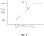
- a threshold 401 is illustrated. Threshold 401 is a function of a vertical speed and forward airspeed.
- the threshold 401 is a maximum allowable descent rate in the vertical axis for a given forward airspeed with the aim of avoiding a potentially dangerous flight condition such as VRS.
- the threshold 401 of the vertical descent speed when the rotorcraft 101 has a forward airspeed of 40 knots (kts) or less, then system 201 will impede a collective control position that would otherwise result in a vertical axis descent rate greater than 800 fpm. As the forward speed of rotorcraft 101 increases and VRS is no longer a concern, the threshold 401 of the vertical descent speed also increases. Once the forward speed of rotorcraft 101 obtains 75 knots, the threshold 401 of the vertical descent speed is capped at 2500 fpm. It should be appreciated that the illustrated threshold 401 is merely an example of an implementation specific threshold curve.
- Selector 209 is configured to identify a vertical speed hold command 205 that would exceed the threshold 401, and replace the vertical speed hold command 205 with the threshold value for the given forward airspeed.
- the threshold value command is received and processed by the vertical speed loop 203 control laws and further commanded to collective actuators 124a-124c. Further, commands can be sent from vertical speed loops 203 to trim motor 127 so that the collective stick 131 is impeded from decreasing collective pitch any further than the threshold value 401.
- the pilot can override system 201 and decrease collective pitch beyond threshold value 401 for a given forward airspeed by overcoming the increase in the collective pitch provided by the system or the impeding force on collective stick 131 provided by trim motor 127.
- System 201 is advantageously configured such that attempted flight into the prohibited part of the flight envelope will result in the vertical speed hold command being modified to the threshold 401, which is a predetermined vertical speed limit at that particular forward airspeed.
- the system 201 may be configured to not only modify the position of collective stick 131 to acquire the vertical speed threshold, but also to produce aural and/or visual alerts to the pilot.
- the pilot can override the vertical speed threshold 401 at any time by applying force/displacement to the collective stick 131.
- the system 201 automatically modulates collective input to preclude the rotorcraft from inadvertently entering dangerously high vertical speed conditions that could otherwise result in VRS, or a crash.
- One advantage of the system 201 of the present disclosure is that it is autonomous, reduces pilot workload, and does not require pilot awareness of the situation, which is one of the inherent dangers.
- Computer system 501 can be configured for performing one or more functions with regard to the operation of the system and method further disclosed herein. Further, any processing and analysis can be partly or fully performed by computer system 501. Computer system 501 can be partly or fully integrated with other aircraft computer systems.
- the system 501 can include an input/output (I/O) interface 503, an analysis engine 505, and a database 507. Alternative examples can combine or distribute the input/output (I/O) interface 503, analysis engine 505, and database 507, as desired.
- Examples of the system 501 can include one or more computers that include one or more processors and memories configured for performing tasks described herein. This can include, for example, a computer having a central processing unit (CPU) and nonvolatile memory such as a non-transitory computer readable medium that stores software instructions for instructing the CPU to perform at least some of the tasks described herein.
- CPU central processing unit
- nonvolatile memory such as a non-transitory computer readable medium that stores software instructions for instructing the CPU to perform at least some of the tasks described herein.
- This can also include, for example, two or more computers that are in communication via a computer network, where one or more of the computers include a CPU and non-volatile memory, and one or more of the computer's non-volatile memory stores software instructions for instructing any of the CPU(s) to perform any of the tasks described herein.
- the example is described in terms of a discrete machine, it should be appreciated that this description is non-limiting, and that the present description applies equally to numerous other arrangements involving one or more machines performing tasks redundantly or distributed in any way among the one or more machines. It should also be appreciated that such machines need not be dedicated to performing tasks described herein, but instead can be multi-purpose machines, for example computer workstations, that are suitable for also performing other tasks.
- the I/O interface 503 can allow one or more remote computer(s) to access information, input information, and/or remotely instruct the system 501 to perform one or more of the tasks described herein.
- the I/O interface 503 can be configured for allowing communication with one or more remote data sources.
- the I/O interface 503 can allow one or more remote data source(s) to access information, input information, and/or remotely instruct the system 501 to perform one or more of the tasks described herein.
- the system 501 may be embodied as a flight control computer (FCC), flight director, partial authority flight control system, or the like.
- An FCC may include a memory having a program stored thereon that, when executed by the processor, cause the processor to implement the control laws that inhibit flight into the prohibited part of the flight envelope.
- the FCC may modify the flight parameters of the rotorcraft according to the power margin of the rotorcraft.
- the FCC may have data associated with the dangerous part of the flight envelope. Flight commands or parameters that would take the rotorcraft into the restricted flight region or dangerous part of the flight envelope may be modified to avoid placing the rotorcraft in danger.
- the restricted flight region 608 may be a region defined by forward airspeed and vertical speed or vertical descent rate, at which a rotorcraft, such as a helicopter, tiltrotor, vertical takeoff craft, or the like, when flying at a particular altitude, weight and temperature, may experience VRS.
- VRS is caused when a rotorcraft descends at the same speed as its vortex wake. The wake coalesces into a powerful vortex ring and the rotor experiences higher than usual downflowing air through the rotor. Relative to the downflowing air, the rotor is effectively placed in a climb state even though the rotorcraft is descending rapidly.
- Rotorcraft typically lack sufficient power and blade collective for overcoming these high rates of downflowing air through the rotor, resulting in the inability to arrest the descent rate.
- the FCC may prevent the rotorcraft from entering a restricted flight region 608 that may be a dangerous part of the flight envelope 600.
- the restricted flight region 608 may be bounded by a VRS boundary 610.
- VRS may be avoided by increasing the forward speed or by reducing descent rate.
- the FCC may use an algorithm to calculate the VRS boundary 610, based, for example, on air density and aircraft gross weight. When the aircraft is below a certain forward airspeed (i.e., 35 knots), the FCC checks if there is sufficient power to avoid an uncommanded high descent rate as speed is further reduced. It should be noted that rotorcraft require increasing power levels to maintain level flight as they reduce airspeed, the highest power condition (for level flight) is hover.
- a rotorcraft may have sufficient power maintain level flight at a particular air speed, but would not be able to hover due to the reduced air density.
- the reduction in air density raises the power required to hover, while reducing the engine power available.
- the difference between power available and power required is called power margin. If the power margin for hover or a reduced flight speed is positive, descent rate must still be managed to avoid VRS, and the FCC can provide a signal to the flight control system to prevent the descent rate from exceeding a limit vertical speed descent rate or vertical speed limit, such as 800 ft./min. or 1000 ft./min..
- the FCC can provide a signal to the flight control system to inhibit further reduction in airspeed or to increase the airspeed, preserving or gaining power margin. With negative power margin, if airspeed is not increased, the rotorcraft descent rate will increase, and the rotorcraft may enter an unsafe VRS boundary 610.
- the FCC may prevent further airspeed reduction or increase forward speed to avoid negative power margin and prevent entering the restricted flight region 608, thus avoiding VRS altogether. For example, the FCC may determine that the power margin at a requested or intended reduced airspeed would initiate an uncommanded descent rate. The FCCs may then cause the rotorcraft to increase its forward speed, for example, by increasing forward cyclic pitch in the rotor system. At low airspeed, increasing the forward airspeed increases the power margin, giving the rotorcraft the ability to manage descent rate and avoid the restricted flight envelope.
- the FCC may generate a cue to the pilot to indicate the best approach for avoiding negative power margin/VRS (collective or forward cyclic) or alert the pilot that the FCC is performing, or about to perform a VRS avoidance maneuver, or that the craft is approaching the VRS region.
- the cue could be a tactile (stick force), visual indication, or an audio command, and may be performed in place if, before, or in conjunction with the VRS avoidance maneuver being performed by the FCC.
- the pilot may respond to the cue to increase forward speed, reduce vertical speed, or implement another maneuver to avoid VRS. Additionally, the cue may be provided until the rotorcraft flight parameters indicate that the rotorcraft is not in danger of entering VRS.
- Fig. 7A illustrates a flight envelope 700 with a safe flight envelope threshold 704 according to some examples.
- the FCC may determine a safe flight envelope threshold 704 for a safe flight region 702 with a vertical speed margin 706 higher than the VRS boundary 610.
- the safe flight envelope threshold 704 may have a variable vertical speed safety threshold 708A, and a forward speed safety threshold 708B.
- the vertical speed margin 706 may, in some examples be calculated according to a portion of the VRS boundary 610.
- the vertical speed margin 706 may be the separation between the variable vertical speed safety threshold 708A and the VRS boundary 610, and may be substantially constant.
- the variable vertical speed safety threshold 708A may vary with forward airspeed 602.
- the forward speed safety threshold 708B may be a speed at which VRS protection is not necessary, and may be at a greater forward speed than the edge of the VRS boundary 610, and may be a forward speed at which VRS protection is not needed.
- Fig. 7B illustrates a flight envelope 750 with a safe flight envelope threshold 754 according to some examples.
- a safe flight envelope threshold 754 may have a constant vertical speed safety threshold 758A and a forward speed safety threshold 758B and may define a safe flight region 752.
- the constant vertical speed safety threshold 758A may be set at a predefined vertical speed, for example, an 800 ft./min. descent rate, a 1000 ft./min. descent rate, or another rate.
- the constant vertical speed safety threshold 758A may be set so that the constant vertical speed safety threshold 758A will be above all portions of the restricted flight region 608 and VRS boundary 610 for all potential rotorcraft operation parameters.
- the constant vertical speed safety threshold 808A and forward speed safety threshold 758B may be set so that the rotorcraft has margin to react and avoid operation in a flight environment that penetrates the VRS boundary 610.
- the constant vertical speed safety threshold 758A being substantially constant, the vertical speed margin 756 depends on, and may be determined according to the forward speed and the VRS boundary 610.
- Fig. 8 illustrates a flight envelope 800 with accelerated flight VRS boundaries 810A, 810B shifted due to maneuvering according to some examples.
- VRS can be disrupted by maneuvering the rotorcraft because the rotor wake has more difficulty coalescing into a vortex ring if the rotorcraft is accelerating.
- the VRS boundary 610 is defined for 1g thrust and relatively steady descent rates. However, it has been determined that the largest VRS boundary 610 is associated with a consistent craft attitude, while maneuvering tends to shift the VRS boundary 610 to a lower accelerated flight VRS boundary 810A, 810B. Additionally, more aggressive maneuvering tends to shrink the VRS boundary 601 to a greater degree.
- a relatively mild maneuver such as an airspeed acceleration
- a more aggressive maneuver such as a descending banked turn with a substantial yaw rate
Landscapes
- Engineering & Computer Science (AREA)
- Aviation & Aerospace Engineering (AREA)
- Mechanical Engineering (AREA)
- Radar, Positioning & Navigation (AREA)
- Remote Sensing (AREA)
- Physics & Mathematics (AREA)
- General Physics & Mathematics (AREA)
- Automation & Control Theory (AREA)
- Control Of Position, Course, Altitude, Or Attitude Of Moving Bodies (AREA)
Claims (14)
- Verfahren (900), umfassend:Überwachen (902) einer Vertikalgeschwindigkeit und einer Vorwärtsgeschwindigkeit eines Drehflügelflugzeugs;Bestimmen (908), ob eine Vermeidung eines Wirbelringzustands (VRS) gemäß mindestens einer von der Vertikalgeschwindigkeit und der Vorwärtsfluggeschwindigkeit des Drehflügelflugzeugs durchzuführen ist; undDurchführen (912, 914), als Reaktion auf das Bestimmen, die VRS-Vermeidung durchzuführen, Steuern eines oder mehrerer Flugparameter des Drehflügelflugzeugs; wobeidas Durchführen gemäß einer Beziehung zwischen einer Leistungsmarge, die von einem oder mehreren Motoren des Drehflügelflugzeugs verfügbar ist, und einem Leistungsmargenschwellenwert durchgeführt wird.
- Verfahren (900) nach Anspruch 1, wobei der eine oder die mehreren Flugparameter mindestens eines von der Vertikalgeschwindigkeit des Drehflügelflugzeugs und der Vorwärtsfluggeschwindigkeit des Drehflügelflugzeugs umfassen und/oder wobei die Vertikalgeschwindigkeit des Drehflügelflugzeugs eine vertikale Sinkgeschwindigkeit des Drehflügelflugzeugs ist.
- Verfahren (900) nach einem der vorherigen Ansprüche, wobei das Bestimmen (908), ob die VRS-Vermeidung durchzuführen ist, ein Bestimmen (908) umfasst, die VRS-Vermeidung als Reaktion darauf durchzuführen, dass die vertikale Sinkgeschwindigkeit einen Vertikalgeschwindigkeit-Sicherheitsschwellenwert überschreitet.
- Verfahren (900) nach Anspruch 3, wobei das Bestimmen (908), ob die VRS-Vermeidung durchzuführen ist, ein Bestimmen (908) umfasst, die VRS-Vermeidung ferner als Reaktion darauf durchzuführen, dass die Vorwärtsfluggeschwindigkeit des Drehflügelflugzeugs unter einem Vorwärtsfluggeschwindigkeit-Sicherheitsschwellenwert ist;
optional wobei der Vertikalgeschwindigkeit-Sicherheitsschwellenwert eine vertikale Sinkgeschwindigkeit ist, die geringer ist als eine VRS-Grenze, die einen eingeschränkten Flugbereich einer Flughülle für das Drehflügelflugzeug definiert, und wobei der Vorwärtsgeschwindigkeit-Schwellenwert größer ist als die VRS-Grenze, die einen eingeschränkten Flugbereich definiert. - Verfahren (900) nach einem der vorherigen Ansprüche, wobei das Überwachen (902), Bestimmen (908) und Durchführen (912, 914) durch ein Computersystem des Drehflügelflugzeugs durchgeführt werden.
- Verfahren (900) nach einem der vorherigen Ansprüche, wobei das Durchführen (912, 914) der Steuerung von einem oder mehreren Flugparametern des Drehflügelflugzeugs ein Begrenzen (912) der vertikalen Sinkgeschwindigkeit des Drehflügelflugzeugs als Reaktion darauf umfasst, dass die Leistungsspanne den Leistungsmargenschwellenwert überschreitet.
- Verfahren (900) nach einem der vorherigen Ansprüche, wobei das Durchführen (912, 914) der Steuerung von einem oder mehreren Flugparametern des Drehflügelflugzeugs ein Erhöhen (914) der Vorwärtsfluggeschwindigkeit des Drehflügelflugzeugs als Reaktion darauf umfasst, dass die Leistungsmargenleistung den Leistungsmargenschwellenwert nicht überschreitet;
optional wobei das Erhöhen (914) der Vorwärtsfluggeschwindigkeit des Drehflügelflugzeugs ein Erhöhen (914) der Vorwärtsfluggeschwindigkeit des Drehflügelflugzeugs umfasst, bis die Vorwärtsfluggeschwindigkeit des Drehflügelflugzeugs einen Vorwärtsfluggeschwindigkeit-Sicherheitsschwellenwert überschreitet. - Verfahren (900) nach einem der vorherigen Ansprüche, wobei die Steuerung von einem oder mehreren Flugparametern des Drehflügelflugzeugs eine Einstellen von einem oder mehreren Flugparametern des Drehflügelflugzeugs umfasst.
- Verfahren (900) nach einem der vorherigen Ansprüche, umfassend ein Bewirken, dass das Drehflügelflugzeug durch die Steuerung eines oder mehrerer Flugparameter des Drehflügelflugzeugs einen Betrieb in der Nähe eines eingeschränkten Bereichs einer Drehflügelflugzeug-Flughülle vermeidet.
- Verfahren (900) nach Anspruch 9, wobei ein Bewirken, dass das Drehflügelflugzeug einen Betrieb zumindest in der Nähe des eingeschränkten Bereichs vermeidet, ein Bewirken umfasst, dass das Drehflügelflugzeugs außerhalb eines Vertikalgeschwindigkeit-Sicherheitsschwellenwert betrieben wird, wobei der Vertikalgeschwindigkeit-Sicherheitsschwellenwert von einem Abschnitt des eingeschränkten Bereichs durch eine Vertikalgeschwindigkeitsmarge getrennt ist.
- Verfahren (900) nach Anspruch 10, wobei Vertikalgeschwindigkeitsmarge von dem eingeschränkten Bereich im Wesentlichen konstant ist und wobei der Vertikalgeschwindigkeit-Sicherheitsschwellenwert mit der Vorwärtsfluggeschwindigkeit variiert und wobei der Vertikalgeschwindigkeit-Sicherheitsschwellenwert außerhalb aller Abschnitte des eingeschränkten Bereichs ist; oder
wobei der Vertikalgeschwindigkeit-Sicherheitsschwellenwert im Wesentlichen konstant ist, wobei der Vertikalgeschwindigkeit-Sicherheitsschwellenwert außerhalb aller Abschnitte des eingeschränkten Bereichs ist, und wobei die Vertikalgeschwindigkeitsmarge mit mindestens der Vorwärtsfluggeschwindigkeit und einer Grenze des eingeschränkten Bereichs assoziiert ist. - Verfahren (900) nach einem der Ansprüche 8 bis 11, wobei das Durchführen (912, 914) ferner ein Bestimmen einer VRS-Grenze für einen beschleunigten Flug des eingeschränkten Bereichs der Flughülle gemäß Betriebsparametern des Drehflügelflugzeugs umfasst, wobei das Durchführen (912, 914) Folgendes umfasst:Steuern (912) der Vertikalgeschwindigkeit des Drehflügelflugzeugs gemäß einem Vertikalgeschwindigkeit-Sicherheitsschwellenwert des beschleunigten Flugs, der mit der VRS-Grenze des beschleunigten Flugs assoziiert ist; und/oderSteuern einer Verschiebung der VRS-Grenze des beschleunigten Flugs durch Einleiten mindestens einer VRS-Unterdrückungstechnik, optional wobei die mindestens eine VRS-Unterdrückungstechnik eines oder mehrere von einer überhöhten Kurve, Erhöhen einer Seitengeschwindigkeit, Erhöhen einer Gier- und der Seitengeschwindigkeit oder einer Rollumkehr umfasst,
- Vorrichtung (501), umfassend:mindestens einen Prozessor (505);ein nicht-transitorische computerlesbares Medium (507), das ein Programm zur Ausführung durch den mindestens einen Prozessor (505) speichert, das Programm umfassend Anweisungen zum Ausführen des Verfahrens (900) nach einem der vorherigen Ansprüche.
- Drehflügelflugzeug (101), umfassend:eine oder mehrere Flugsteuerungen (131, 133); undeinen Flugsteuerungscomputer, FCC, (125), der konfiguriert ist, um das Verfahren (900) nach einem der Ansprüche 1 bis 12 durchzuführen.
Priority Applications (1)
| Application Number | Priority Date | Filing Date | Title |
|---|---|---|---|
| EP25155869.8A EP4538827B1 (de) | 2019-12-31 | 2020-04-15 | System und verfahren zum schutz vor wirbelringzustand |
Applications Claiming Priority (3)
| Application Number | Priority Date | Filing Date | Title |
|---|---|---|---|
| US201962955855P | 2019-12-31 | 2019-12-31 | |
| US16/790,304 US11554855B2 (en) | 2019-12-31 | 2020-02-13 | System and method for protection against vortex ring state |
| EP20169656.4A EP3882734B1 (de) | 2019-12-31 | 2020-04-15 | Verfahren zur verhinderung von wirbelringstadium und einrichtung dazu |
Related Parent Applications (1)
| Application Number | Title | Priority Date | Filing Date |
|---|---|---|---|
| EP20169656.4A Division EP3882734B1 (de) | 2019-12-31 | 2020-04-15 | Verfahren zur verhinderung von wirbelringstadium und einrichtung dazu |
Related Child Applications (1)
| Application Number | Title | Priority Date | Filing Date |
|---|---|---|---|
| EP25155869.8A Division EP4538827B1 (de) | 2019-12-31 | 2020-04-15 | System und verfahren zum schutz vor wirbelringzustand |
Publications (3)
| Publication Number | Publication Date |
|---|---|
| EP4365079A2 EP4365079A2 (de) | 2024-05-08 |
| EP4365079A3 EP4365079A3 (de) | 2024-05-22 |
| EP4365079B1 true EP4365079B1 (de) | 2025-03-05 |
Family
ID=76545871
Family Applications (3)
| Application Number | Title | Priority Date | Filing Date |
|---|---|---|---|
| EP25155869.8A Active EP4538827B1 (de) | 2019-12-31 | 2020-04-15 | System und verfahren zum schutz vor wirbelringzustand |
| EP20169656.4A Active EP3882734B1 (de) | 2019-12-31 | 2020-04-15 | Verfahren zur verhinderung von wirbelringstadium und einrichtung dazu |
| EP24164217.2A Active EP4365079B1 (de) | 2019-12-31 | 2020-04-15 | Verfahren zum schutz vor wirbelringzustand und zugehörige vorrichtung |
Family Applications Before (2)
| Application Number | Title | Priority Date | Filing Date |
|---|---|---|---|
| EP25155869.8A Active EP4538827B1 (de) | 2019-12-31 | 2020-04-15 | System und verfahren zum schutz vor wirbelringzustand |
| EP20169656.4A Active EP3882734B1 (de) | 2019-12-31 | 2020-04-15 | Verfahren zur verhinderung von wirbelringstadium und einrichtung dazu |
Country Status (3)
| Country | Link |
|---|---|
| US (3) | US11554855B2 (de) |
| EP (3) | EP4538827B1 (de) |
| CN (1) | CN113120227A (de) |
Families Citing this family (9)
| Publication number | Priority date | Publication date | Assignee | Title |
|---|---|---|---|---|
| US11554855B2 (en) * | 2019-12-31 | 2023-01-17 | Textron Innovations Inc. | System and method for protection against vortex ring state |
| WO2022049764A1 (ja) * | 2020-09-07 | 2022-03-10 | 株式会社エアロネクスト | 飛行体 |
| EP4015375B1 (de) * | 2020-12-21 | 2023-03-01 | LEONARDO S.p.A. | Indikator für ein schwebefähiges flugzeug und verfahren zur unterstützung der durchführung eines manövers für dieses flugzeug |
| US11801936B2 (en) * | 2021-01-19 | 2023-10-31 | Textron Innovations Inc. | Preventing helicopter loss of tail rotor effectiveness |
| US11731757B2 (en) * | 2021-11-05 | 2023-08-22 | Karem Aircraft, Inc. | Rotor blade pitch trajectory control |
| US11975860B2 (en) | 2022-01-06 | 2024-05-07 | Textron Innovations Inc. | Reduced-engine operation technique for rotorcraft |
| EP4743848A1 (de) | 2023-07-10 | 2026-05-20 | Archer Aviation Inc | Systeme und verfahren für propellerschubschutz |
| WO2025208156A1 (en) * | 2024-03-29 | 2025-10-02 | Archer Aviation Inc. | Systems and methods for autopilot interface and nudge control |
| CN120010511B (zh) * | 2025-02-12 | 2025-11-28 | 广东汇天航空航天科技有限公司 | 一种飞行器的倾转控制方法以及电子设备 |
Family Cites Families (17)
| Publication number | Priority date | Publication date | Assignee | Title |
|---|---|---|---|---|
| US6171056B1 (en) * | 1998-12-23 | 2001-01-09 | Sikorsky Aircraft Corporation | Technique for providing a signal for controlling blade vortex interaction noise of a rotorcraft |
| CA2392734C (en) * | 2000-05-16 | 2009-01-20 | Bell Helicopter Textron Inc. | Multi-mode tiltrotor nacelle control system with integrated envelope protection |
| DE10144484B4 (de) * | 2001-09-10 | 2006-03-02 | Eurocopter Deutschland Gmbh | Verfahren zur Vermeidung einer Kollision eines rotierenden Rotorblattes eines Drehflügers mit einem Blattwirbel und Vorrichtung zur Durchführung des Verfahrens |
| US6880782B2 (en) * | 2003-05-06 | 2005-04-19 | Bell Helicopter Textron Inc. | Control system for rotorcraft for preventing the vortex ring state |
| AU2003301511A1 (en) * | 2003-07-25 | 2005-02-14 | Nikolai Alekseevich Baranov | Integrated system for aircraft vortex safety |
| DE102010027081B4 (de) * | 2010-07-13 | 2016-02-11 | Deutsches Zentrum für Luft- und Raumfahrt e.V. | Früherkennung eines Wirbelringstadiums |
| FR2973340B1 (fr) * | 2011-03-30 | 2013-04-12 | Eurocopter France | Procede, dispositif d'aide au pilotage d'un aeronef, et aeronef |
| US9886039B2 (en) | 2014-02-17 | 2018-02-06 | Bell Helicopter Textron Inc. | System and method for avoiding inadvertant entry into an unsafe vertical descent speed region for rotorcraft |
| FR3028495B1 (fr) * | 2014-11-14 | 2016-11-18 | Airbus Helicopters | Procede et dispositif pour commander au moins deux sous systemes d'un aeronef |
| US9511880B2 (en) * | 2015-03-31 | 2016-12-06 | Honeywell International Inc. | Flight deck display systems and methods for generating vertical speed alerts during steep approaches of rotary wing aircraft |
| FR3053025B1 (fr) * | 2016-06-28 | 2018-06-15 | Airbus Helicopters | Amelioration de la detection et de signalisation de l'approche du domaine de vortex par un giravion |
| US10101749B1 (en) * | 2017-03-21 | 2018-10-16 | Bell Helicopter Textron Inc. | Combined airspeed and inertial data for rotorcraft longitudinal control |
| FR3066756A1 (fr) * | 2017-05-24 | 2018-11-30 | Airbus Helicopters | Procede et systeme d'anticipation de l'entree dans un domaine de vortex par un giravion |
| EP3477261B1 (de) | 2017-10-26 | 2020-02-26 | Bell Helicopter Textron Inc. | Fluginstrumentwarnanzeige |
| CN109018397B (zh) * | 2018-08-13 | 2020-04-03 | 南京航空航天大学 | 基于气动噪声监测的旋翼涡环状态自动预警系统及方法 |
| US11554855B2 (en) * | 2019-12-31 | 2023-01-17 | Textron Innovations Inc. | System and method for protection against vortex ring state |
| US11435761B1 (en) * | 2021-07-23 | 2022-09-06 | Beta Air, Llc | System and method for distributed flight control system for an electric vehicle |
-
2020
- 2020-02-13 US US16/790,304 patent/US11554855B2/en active Active
- 2020-04-09 CN CN202010274448.8A patent/CN113120227A/zh active Pending
- 2020-04-15 EP EP25155869.8A patent/EP4538827B1/de active Active
- 2020-04-15 EP EP20169656.4A patent/EP3882734B1/de active Active
- 2020-04-15 EP EP24164217.2A patent/EP4365079B1/de active Active
-
2023
- 2023-01-11 US US18/152,924 patent/US12054244B2/en active Active
-
2024
- 2024-07-16 US US18/774,671 patent/US12509222B2/en active Active
Also Published As
| Publication number | Publication date |
|---|---|
| US12054244B2 (en) | 2024-08-06 |
| CN113120227A (zh) | 2021-07-16 |
| EP4538827A3 (de) | 2025-04-30 |
| EP4538827B1 (de) | 2026-01-28 |
| EP4365079A2 (de) | 2024-05-08 |
| US20240367785A1 (en) | 2024-11-07 |
| EP4365079A3 (de) | 2024-05-22 |
| EP3882734B1 (de) | 2024-04-10 |
| EP4538827A2 (de) | 2025-04-16 |
| US20210197962A1 (en) | 2021-07-01 |
| US20230150656A1 (en) | 2023-05-18 |
| US12509222B2 (en) | 2025-12-30 |
| EP3882734A1 (de) | 2021-09-22 |
| US11554855B2 (en) | 2023-01-17 |
Similar Documents
| Publication | Publication Date | Title |
|---|---|---|
| US12509222B2 (en) | System and method for protection against vortex ring state | |
| US11208205B2 (en) | System and method for rotorcraft autorotation entry assist | |
| EP2810873B1 (de) | System und Verfahren zur Unterstützung der Rotordrehzahlsteuerung | |
| EP3578458B1 (de) | System und verfahren zur höhensteuerung eines drehflüglers | |
| US11599111B2 (en) | Reverse tactile cue for rotorcraft rotor overspeed protection | |
| EP3560824B1 (de) | System und verfahren für automatischen heckschlagschutz eines drehflügelflugzeuges | |
| US11801936B2 (en) | Preventing helicopter loss of tail rotor effectiveness | |
| EP2810872B1 (de) | System und Verfahren zur Maximierung der sicheren Flugzeuglandefähigkeit während des Betriebs mit einem betriebsunfähigen Motor | |
| US9886039B2 (en) | System and method for avoiding inadvertant entry into an unsafe vertical descent speed region for rotorcraft | |
| EP3599160B1 (de) | System und verfahren zur flugsteuerung eines drehflüglers | |
| EP3388335A1 (de) | Standardmässiges halten der steig- und sinkgeschwindigkeit/höhe | |
| EP2813427B1 (de) | Auf Drehmoment basierendes Verfahren zur Begrenzung der Vertikalachsenzunahme | |
| EP3492373A1 (de) | System und verfahren zur flugmodusanzeige | |
| US10359785B2 (en) | Touchdown orientation control system for a rotary wing aircraft and method |
Legal Events
| Date | Code | Title | Description |
|---|---|---|---|
| PUAI | Public reference made under article 153(3) epc to a published international application that has entered the european phase |
Free format text: ORIGINAL CODE: 0009012 |
|
| STAA | Information on the status of an ep patent application or granted ep patent |
Free format text: STATUS: REQUEST FOR EXAMINATION WAS MADE |
|
| REG | Reference to a national code |
Ref country code: DE Ref legal event code: R079 Free format text: PREVIOUS MAIN CLASS: B64C0027000000 Ipc: G05D0001000000 Ref country code: DE Ref legal event code: R079 Ref document number: 602020047483 Country of ref document: DE Free format text: PREVIOUS MAIN CLASS: B64C0027000000 Ipc: G05D0001000000 |
|
| PUAL | Search report despatched |
Free format text: ORIGINAL CODE: 0009013 |
|
| STAA | Information on the status of an ep patent application or granted ep patent |
Free format text: STATUS: EXAMINATION IS IN PROGRESS |
|
| 17P | Request for examination filed |
Effective date: 20240318 |
|
| AC | Divisional application: reference to earlier application |
Ref document number: 3882734 Country of ref document: EP Kind code of ref document: P |
|
| AK | Designated contracting states |
Kind code of ref document: A2 Designated state(s): AL AT BE BG CH CY CZ DE DK EE ES FI FR GB GR HR HU IE IS IT LI LT LU LV MC MK MT NL NO PL PT RO RS SE SI SK SM TR |
|
| AK | Designated contracting states |
Kind code of ref document: A3 Designated state(s): AL AT BE BG CH CY CZ DE DK EE ES FI FR GB GR HR HU IE IS IT LI LT LU LV MC MK MT NL NO PL PT RO RS SE SI SK SM TR |
|
| RIC1 | Information provided on ipc code assigned before grant |
Ipc: G05D 109/25 20240101ALI20240416BHEP Ipc: G05D 105/22 20240101ALI20240416BHEP Ipc: G05D 1/82 20240101ALI20240416BHEP Ipc: G05D 1/81 20240101ALI20240416BHEP Ipc: B64D 31/06 20240101ALI20240416BHEP Ipc: G05D 1/485 20240101ALI20240416BHEP Ipc: B64C 27/00 20060101ALI20240416BHEP Ipc: B64C 27/57 20060101ALI20240416BHEP Ipc: B64C 27/04 20060101ALI20240416BHEP Ipc: G05D 1/00 20240101AFI20240416BHEP |
|
| 17Q | First examination report despatched |
Effective date: 20240506 |
|
| REG | Reference to a national code |
Ref country code: DE Ref legal event code: R079 Ipc: B64C0027040000 Ref document number: 602020047483 Country of ref document: DE Free format text: PREVIOUS MAIN CLASS: G05D0001000000 |
|
| RIC1 | Information provided on ipc code assigned before grant |
Ipc: G05D 109/25 20240101ALI20240913BHEP Ipc: G05D 105/22 20240101ALI20240913BHEP Ipc: G05D 1/82 20240101ALI20240913BHEP Ipc: G05D 1/81 20240101ALI20240913BHEP Ipc: B64D 31/06 20240101ALI20240913BHEP Ipc: G05D 1/485 20240101ALI20240913BHEP Ipc: B64C 27/00 20060101ALI20240913BHEP Ipc: B64C 27/57 20060101ALI20240913BHEP Ipc: B64C 27/04 20060101AFI20240913BHEP |
|
| GRAP | Despatch of communication of intention to grant a patent |
Free format text: ORIGINAL CODE: EPIDOSNIGR1 |
|
| STAA | Information on the status of an ep patent application or granted ep patent |
Free format text: STATUS: GRANT OF PATENT IS INTENDED |
|
| INTG | Intention to grant announced |
Effective date: 20241028 |
|
| GRAS | Grant fee paid |
Free format text: ORIGINAL CODE: EPIDOSNIGR3 |
|
| GRAA | (expected) grant |
Free format text: ORIGINAL CODE: 0009210 |
|
| STAA | Information on the status of an ep patent application or granted ep patent |
Free format text: STATUS: THE PATENT HAS BEEN GRANTED |
|
| AC | Divisional application: reference to earlier application |
Ref document number: 3882734 Country of ref document: EP Kind code of ref document: P |
|
| AK | Designated contracting states |
Kind code of ref document: B1 Designated state(s): AL AT BE BG CH CY CZ DE DK EE ES FI FR GB GR HR HU IE IS IT LI LT LU LV MC MK MT NL NO PL PT RO RS SE SI SK SM TR |
|
| REG | Reference to a national code |
Ref country code: GB Ref legal event code: FG4D |
|
| P01 | Opt-out of the competence of the unified patent court (upc) registered |
Free format text: CASE NUMBER: APP_5018/2025 Effective date: 20250130 |
|
| REG | Reference to a national code |
Ref country code: CH Ref legal event code: EP |
|
| REG | Reference to a national code |
Ref country code: DE Ref legal event code: R096 Ref document number: 602020047483 Country of ref document: DE |
|
| REG | Reference to a national code |
Ref country code: IE Ref legal event code: FG4D |
|
| PG25 | Lapsed in a contracting state [announced via postgrant information from national office to epo] |
Ref country code: RS Free format text: LAPSE BECAUSE OF FAILURE TO SUBMIT A TRANSLATION OF THE DESCRIPTION OR TO PAY THE FEE WITHIN THE PRESCRIBED TIME-LIMIT Effective date: 20250605 |
|
| PG25 | Lapsed in a contracting state [announced via postgrant information from national office to epo] |
Ref country code: FI Free format text: LAPSE BECAUSE OF FAILURE TO SUBMIT A TRANSLATION OF THE DESCRIPTION OR TO PAY THE FEE WITHIN THE PRESCRIBED TIME-LIMIT Effective date: 20250305 |
|
| PGFP | Annual fee paid to national office [announced via postgrant information from national office to epo] |
Ref country code: DE Payment date: 20250429 Year of fee payment: 6 |
|
| REG | Reference to a national code |
Ref country code: NL Ref legal event code: MP Effective date: 20250305 |
|
| PG25 | Lapsed in a contracting state [announced via postgrant information from national office to epo] |
Ref country code: ES Free format text: LAPSE BECAUSE OF FAILURE TO SUBMIT A TRANSLATION OF THE DESCRIPTION OR TO PAY THE FEE WITHIN THE PRESCRIBED TIME-LIMIT Effective date: 20250305 |
|
| PGFP | Annual fee paid to national office [announced via postgrant information from national office to epo] |
Ref country code: GB Payment date: 20250428 Year of fee payment: 6 |
|
| REG | Reference to a national code |
Ref country code: LT Ref legal event code: MG9D |
|
| PG25 | Lapsed in a contracting state [announced via postgrant information from national office to epo] |
Ref country code: NO Free format text: LAPSE BECAUSE OF FAILURE TO SUBMIT A TRANSLATION OF THE DESCRIPTION OR TO PAY THE FEE WITHIN THE PRESCRIBED TIME-LIMIT Effective date: 20250605 |
|
| PG25 | Lapsed in a contracting state [announced via postgrant information from national office to epo] |
Ref country code: HR Free format text: LAPSE BECAUSE OF FAILURE TO SUBMIT A TRANSLATION OF THE DESCRIPTION OR TO PAY THE FEE WITHIN THE PRESCRIBED TIME-LIMIT Effective date: 20250305 |
|
| PG25 | Lapsed in a contracting state [announced via postgrant information from national office to epo] |
Ref country code: LV Free format text: LAPSE BECAUSE OF FAILURE TO SUBMIT A TRANSLATION OF THE DESCRIPTION OR TO PAY THE FEE WITHIN THE PRESCRIBED TIME-LIMIT Effective date: 20250305 |
|
| PGFP | Annual fee paid to national office [announced via postgrant information from national office to epo] |
Ref country code: FR Payment date: 20250425 Year of fee payment: 6 |
|
| PG25 | Lapsed in a contracting state [announced via postgrant information from national office to epo] |
Ref country code: GR Free format text: LAPSE BECAUSE OF FAILURE TO SUBMIT A TRANSLATION OF THE DESCRIPTION OR TO PAY THE FEE WITHIN THE PRESCRIBED TIME-LIMIT Effective date: 20250606 Ref country code: BG Free format text: LAPSE BECAUSE OF FAILURE TO SUBMIT A TRANSLATION OF THE DESCRIPTION OR TO PAY THE FEE WITHIN THE PRESCRIBED TIME-LIMIT Effective date: 20250305 |
|
| PG25 | Lapsed in a contracting state [announced via postgrant information from national office to epo] |
Ref country code: NL Free format text: LAPSE BECAUSE OF FAILURE TO SUBMIT A TRANSLATION OF THE DESCRIPTION OR TO PAY THE FEE WITHIN THE PRESCRIBED TIME-LIMIT Effective date: 20250305 |
|
| PG25 | Lapsed in a contracting state [announced via postgrant information from national office to epo] |
Ref country code: SE Free format text: LAPSE BECAUSE OF FAILURE TO SUBMIT A TRANSLATION OF THE DESCRIPTION OR TO PAY THE FEE WITHIN THE PRESCRIBED TIME-LIMIT Effective date: 20250305 |
|
| PG25 | Lapsed in a contracting state [announced via postgrant information from national office to epo] |
Ref country code: SM Free format text: LAPSE BECAUSE OF FAILURE TO SUBMIT A TRANSLATION OF THE DESCRIPTION OR TO PAY THE FEE WITHIN THE PRESCRIBED TIME-LIMIT Effective date: 20250305 |
|
| PG25 | Lapsed in a contracting state [announced via postgrant information from national office to epo] |
Ref country code: PT Free format text: LAPSE BECAUSE OF FAILURE TO SUBMIT A TRANSLATION OF THE DESCRIPTION OR TO PAY THE FEE WITHIN THE PRESCRIBED TIME-LIMIT Effective date: 20250707 |
|
| PG25 | Lapsed in a contracting state [announced via postgrant information from national office to epo] |
Ref country code: PL Free format text: LAPSE BECAUSE OF FAILURE TO SUBMIT A TRANSLATION OF THE DESCRIPTION OR TO PAY THE FEE WITHIN THE PRESCRIBED TIME-LIMIT Effective date: 20250305 Ref country code: IT Free format text: LAPSE BECAUSE OF FAILURE TO SUBMIT A TRANSLATION OF THE DESCRIPTION OR TO PAY THE FEE WITHIN THE PRESCRIBED TIME-LIMIT Effective date: 20250305 |
|
| PG25 | Lapsed in a contracting state [announced via postgrant information from national office to epo] |
Ref country code: AT Free format text: LAPSE BECAUSE OF FAILURE TO SUBMIT A TRANSLATION OF THE DESCRIPTION OR TO PAY THE FEE WITHIN THE PRESCRIBED TIME-LIMIT Effective date: 20250305 |
|
| PG25 | Lapsed in a contracting state [announced via postgrant information from national office to epo] |
Ref country code: EE Free format text: LAPSE BECAUSE OF FAILURE TO SUBMIT A TRANSLATION OF THE DESCRIPTION OR TO PAY THE FEE WITHIN THE PRESCRIBED TIME-LIMIT Effective date: 20250305 Ref country code: CZ Free format text: LAPSE BECAUSE OF FAILURE TO SUBMIT A TRANSLATION OF THE DESCRIPTION OR TO PAY THE FEE WITHIN THE PRESCRIBED TIME-LIMIT Effective date: 20250305 |
|
| PG25 | Lapsed in a contracting state [announced via postgrant information from national office to epo] |
Ref country code: RO Free format text: LAPSE BECAUSE OF FAILURE TO SUBMIT A TRANSLATION OF THE DESCRIPTION OR TO PAY THE FEE WITHIN THE PRESCRIBED TIME-LIMIT Effective date: 20250305 |
|
| PG25 | Lapsed in a contracting state [announced via postgrant information from national office to epo] |
Ref country code: SK Free format text: LAPSE BECAUSE OF FAILURE TO SUBMIT A TRANSLATION OF THE DESCRIPTION OR TO PAY THE FEE WITHIN THE PRESCRIBED TIME-LIMIT Effective date: 20250305 |
|
| PG25 | Lapsed in a contracting state [announced via postgrant information from national office to epo] |
Ref country code: IS Free format text: LAPSE BECAUSE OF FAILURE TO SUBMIT A TRANSLATION OF THE DESCRIPTION OR TO PAY THE FEE WITHIN THE PRESCRIBED TIME-LIMIT Effective date: 20250705 |
|
| REG | Reference to a national code |
Ref country code: CH Ref legal event code: H13 Free format text: ST27 STATUS EVENT CODE: U-0-0-H10-H13 (AS PROVIDED BY THE NATIONAL OFFICE) Effective date: 20251125 |
|
| REG | Reference to a national code |
Ref country code: DE Ref legal event code: R097 Ref document number: 602020047483 Country of ref document: DE |
|
| PG25 | Lapsed in a contracting state [announced via postgrant information from national office to epo] |
Ref country code: LU Free format text: LAPSE BECAUSE OF NON-PAYMENT OF DUE FEES Effective date: 20250415 |
|
| PG25 | Lapsed in a contracting state [announced via postgrant information from national office to epo] |
Ref country code: MC Free format text: LAPSE BECAUSE OF FAILURE TO SUBMIT A TRANSLATION OF THE DESCRIPTION OR TO PAY THE FEE WITHIN THE PRESCRIBED TIME-LIMIT Effective date: 20250305 |
|
| REG | Reference to a national code |
Ref country code: BE Ref legal event code: MM Effective date: 20250430 |
|
| PLBE | No opposition filed within time limit |
Free format text: ORIGINAL CODE: 0009261 |
|
| STAA | Information on the status of an ep patent application or granted ep patent |
Free format text: STATUS: NO OPPOSITION FILED WITHIN TIME LIMIT |
|
| PG25 | Lapsed in a contracting state [announced via postgrant information from national office to epo] |
Ref country code: DK Free format text: LAPSE BECAUSE OF FAILURE TO SUBMIT A TRANSLATION OF THE DESCRIPTION OR TO PAY THE FEE WITHIN THE PRESCRIBED TIME-LIMIT Effective date: 20250305 |
|
| REG | Reference to a national code |
Ref country code: CH Ref legal event code: L10 Free format text: ST27 STATUS EVENT CODE: U-0-0-L10-L00 (AS PROVIDED BY THE NATIONAL OFFICE) Effective date: 20260114 |
|
| PG25 | Lapsed in a contracting state [announced via postgrant information from national office to epo] |
Ref country code: BE Free format text: LAPSE BECAUSE OF NON-PAYMENT OF DUE FEES Effective date: 20250430 |
|
| PG25 | Lapsed in a contracting state [announced via postgrant information from national office to epo] |
Ref country code: CH Free format text: LAPSE BECAUSE OF NON-PAYMENT OF DUE FEES Effective date: 20250430 |
|
| 26N | No opposition filed |
Effective date: 20251208 |
|
| PG25 | Lapsed in a contracting state [announced via postgrant information from national office to epo] |
Ref country code: IE Free format text: LAPSE BECAUSE OF NON-PAYMENT OF DUE FEES Effective date: 20250415 |