EP4364921A1 - Injection molding machine - Google Patents
Injection molding machine Download PDFInfo
- Publication number
- EP4364921A1 EP4364921A1 EP22833028.8A EP22833028A EP4364921A1 EP 4364921 A1 EP4364921 A1 EP 4364921A1 EP 22833028 A EP22833028 A EP 22833028A EP 4364921 A1 EP4364921 A1 EP 4364921A1
- Authority
- EP
- European Patent Office
- Prior art keywords
- bed
- molding machine
- injection molding
- hydraulic pump
- machine according
- Prior art date
- Legal status (The legal status is an assumption and is not a legal conclusion. Google has not performed a legal analysis and makes no representation as to the accuracy of the status listed.)
- Pending
Links
Images


Classifications
-
- B—PERFORMING OPERATIONS; TRANSPORTING
- B29—WORKING OF PLASTICS; WORKING OF SUBSTANCES IN A PLASTIC STATE IN GENERAL
- B29C—SHAPING OR JOINING OF PLASTICS; SHAPING OF MATERIAL IN A PLASTIC STATE, NOT OTHERWISE PROVIDED FOR; AFTER-TREATMENT OF THE SHAPED PRODUCTS, e.g. REPAIRING
- B29C45/00—Injection moulding, i.e. forcing the required volume of moulding material through a nozzle into a closed mould; Apparatus therefor
- B29C45/17—Component parts, details or accessories; Auxiliary operations
- B29C45/1773—Means for adjusting or displacing the injection unit into different positions, e.g. for co-operating with different moulds
-
- B—PERFORMING OPERATIONS; TRANSPORTING
- B29—WORKING OF PLASTICS; WORKING OF SUBSTANCES IN A PLASTIC STATE IN GENERAL
- B29C—SHAPING OR JOINING OF PLASTICS; SHAPING OF MATERIAL IN A PLASTIC STATE, NOT OTHERWISE PROVIDED FOR; AFTER-TREATMENT OF THE SHAPED PRODUCTS, e.g. REPAIRING
- B29C45/00—Injection moulding, i.e. forcing the required volume of moulding material through a nozzle into a closed mould; Apparatus therefor
- B29C45/03—Injection moulding apparatus
- B29C45/07—Injection moulding apparatus using movable injection units
-
- B—PERFORMING OPERATIONS; TRANSPORTING
- B29—WORKING OF PLASTICS; WORKING OF SUBSTANCES IN A PLASTIC STATE IN GENERAL
- B29C—SHAPING OR JOINING OF PLASTICS; SHAPING OF MATERIAL IN A PLASTIC STATE, NOT OTHERWISE PROVIDED FOR; AFTER-TREATMENT OF THE SHAPED PRODUCTS, e.g. REPAIRING
- B29C45/00—Injection moulding, i.e. forcing the required volume of moulding material through a nozzle into a closed mould; Apparatus therefor
- B29C45/17—Component parts, details or accessories; Auxiliary operations
- B29C45/1761—Means for guiding movable mould supports or injection units on the machine base or frame; Machine bases or frames
-
- B—PERFORMING OPERATIONS; TRANSPORTING
- B29—WORKING OF PLASTICS; WORKING OF SUBSTANCES IN A PLASTIC STATE IN GENERAL
- B29C—SHAPING OR JOINING OF PLASTICS; SHAPING OF MATERIAL IN A PLASTIC STATE, NOT OTHERWISE PROVIDED FOR; AFTER-TREATMENT OF THE SHAPED PRODUCTS, e.g. REPAIRING
- B29C45/00—Injection moulding, i.e. forcing the required volume of moulding material through a nozzle into a closed mould; Apparatus therefor
- B29C45/17—Component parts, details or accessories; Auxiliary operations
- B29C45/1777—Nozzle touch mechanism
-
- B—PERFORMING OPERATIONS; TRANSPORTING
- B29—WORKING OF PLASTICS; WORKING OF SUBSTANCES IN A PLASTIC STATE IN GENERAL
- B29C—SHAPING OR JOINING OF PLASTICS; SHAPING OF MATERIAL IN A PLASTIC STATE, NOT OTHERWISE PROVIDED FOR; AFTER-TREATMENT OF THE SHAPED PRODUCTS, e.g. REPAIRING
- B29C45/00—Injection moulding, i.e. forcing the required volume of moulding material through a nozzle into a closed mould; Apparatus therefor
- B29C45/17—Component parts, details or accessories; Auxiliary operations
- B29C45/46—Means for plasticising or homogenising the moulding material or forcing it into the mould
- B29C45/47—Means for plasticising or homogenising the moulding material or forcing it into the mould using screws
- B29C45/50—Axially movable screw
- B29C45/5008—Drive means therefor
-
- B—PERFORMING OPERATIONS; TRANSPORTING
- B29—WORKING OF PLASTICS; WORKING OF SUBSTANCES IN A PLASTIC STATE IN GENERAL
- B29C—SHAPING OR JOINING OF PLASTICS; SHAPING OF MATERIAL IN A PLASTIC STATE, NOT OTHERWISE PROVIDED FOR; AFTER-TREATMENT OF THE SHAPED PRODUCTS, e.g. REPAIRING
- B29C45/00—Injection moulding, i.e. forcing the required volume of moulding material through a nozzle into a closed mould; Apparatus therefor
- B29C45/17—Component parts, details or accessories; Auxiliary operations
- B29C45/76—Measuring, controlling or regulating
- B29C45/82—Hydraulic or pneumatic circuits
-
- B—PERFORMING OPERATIONS; TRANSPORTING
- B29—WORKING OF PLASTICS; WORKING OF SUBSTANCES IN A PLASTIC STATE IN GENERAL
- B29C—SHAPING OR JOINING OF PLASTICS; SHAPING OF MATERIAL IN A PLASTIC STATE, NOT OTHERWISE PROVIDED FOR; AFTER-TREATMENT OF THE SHAPED PRODUCTS, e.g. REPAIRING
- B29C45/00—Injection moulding, i.e. forcing the required volume of moulding material through a nozzle into a closed mould; Apparatus therefor
- B29C45/17—Component parts, details or accessories; Auxiliary operations
- B29C2045/1784—Component parts, details or accessories not otherwise provided for; Auxiliary operations not otherwise provided for
- B29C2045/1785—Movement of a part, e.g. opening or closing movement of the mould, generating fluid pressure in a built-in fluid pressure generator
-
- B—PERFORMING OPERATIONS; TRANSPORTING
- B29—WORKING OF PLASTICS; WORKING OF SUBSTANCES IN A PLASTIC STATE IN GENERAL
- B29C—SHAPING OR JOINING OF PLASTICS; SHAPING OF MATERIAL IN A PLASTIC STATE, NOT OTHERWISE PROVIDED FOR; AFTER-TREATMENT OF THE SHAPED PRODUCTS, e.g. REPAIRING
- B29C2945/00—Indexing scheme relating to injection moulding, i.e. forcing the required volume of moulding material through a nozzle into a closed mould
- B29C2945/76—Measuring, controlling or regulating
- B29C2945/76655—Location of control
- B29C2945/76775—Fluids
- B29C2945/76785—Fluids hydraulic fluids
Definitions
- the present invention relates to an injection molding machine including an injection device provided to be movable on a bed, a mold clamping device provided on the bed, and a movement device for moving the injection device toward and away from the mold clamping device.
- each device is provided on a bed. That is, an injection device is provided to be movable on the bed, and a mold clamping device is provided on the bed.
- the injection device includes a nozzle touch device, that is, a movement device.
- the movement device includes an oil hydraulic cylinder, and when pressure oil is supplied to the oil hydraulic cylinder, the injection device moves. Accordingly, the injection device is moved toward or away from the mold clamping device.
- Patent Literature 1 JP2009-255476A
- An injection molding machine includes one or more control panels for driving each device. Such a control panel is provided below an injection device in a bed.
- a movement device includes an oil hydraulic pump for supplying pressure oil to the oil hydraulic pump, a motor configured to drive the oil hydraulic pump, and the like.
- the oil hydraulic pump and the like causes a failure when a control panel and the like is contaminated due to leakage of the pressure oil, and therefore, it is necessary to consider an installation location of the oil hydraulic pump and the like. That is, it is not preferable to place the oil hydraulic pump and the like on the bed. Accordingly, the oil hydraulic pump and the like of the movement device is provided on a lateral side of the bed. There is a problem that the oil hydraulic pump protrudes from the lateral side of the bed, and the appearance is impaired.
- an object of the present disclosure is to provide an injection molding machine that does not impair the appearance.
- the present inventors have found that the above problem can be solved by providing a hydraulic pump in a bed.
- the hydraulic pump supplies a working fluid to a hydraulic cylinder of a movement device.
- an oil hydraulic cylinder and an oil hydraulic pump are used as the hydraulic cylinder and the hydraulic pump, respectively.
- an injection molding machine 1 includes a mold clamping device 2 placed on a bed B, and an injection device 3 provided on the bed B.
- the injection molding machine 1 is provided with a nozzle touch device, that is, a movement device 5, which will be described in detail later, and which is configured to cause the injection device 3 to be moved toward or away from the mold clamping device 2.
- the mold clamping device 2 and the injection device 3 are driven by an electric servo motor or the like. That is, the injection molding machine 1 according to the present embodiment is a so-called electric injection molding machine.
- the injection molding machine 1 includes a controller 7.
- the controller 7 is not shown to avoid complication of the drawing.
- the controller 7 is configured to control the mold clamping device 2, the injection device 3, and the like.
- an operation side S1 a side on which the controller 7 is provided
- an opposite side is referred to as a counter operation side S2.
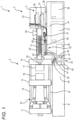
- FIG. 1 is a front view of the injection molding machine 1 viewed from the operation side S 1.
- the injection molding machine includes a mold clamping device provided on a bed.
- the mold clamping device 2 includes a fixed platen 10 fixed on the bed B, a mold clamping housing 11 slidable on the bed B, and a movable platen 12 also slidable on the bed B.
- the fixed platen 10 and the mold clamping housing 11 are connected by a plurality of, for example, four tie bars 14, 14 ...
- the movable platen 12 is slidable between the fixed platen 10 and the mold clamping housing 11.
- a mold clamping mechanism 16 configured by a toggle mechanism is provided between the mold clamping housing 11 and the movable platen 12.
- the mold clamping mechanism 16 may be a direct-pressure type mold clamping cylinder.
- the fixed platen 10 and the movable platen 12 are provided with a fixed side mold 17 and a movable side mold 18, respectively. The molds are opened and closed when the mold clamping mechanism 16 is driven by an electric servo motor (not shown).
- the injection molding machine includes an injection device provided to be movable with respect to a bed.
- the injection device 3 includes a heating cylinder 20, a screw 21 inserted in the heating cylinder 20, and a screw driving device 23 for driving the screw 21.
- the heating cylinder 20 is provided with a hopper 25 and an injection nozzle 26.
- the screw 21 is rotated and a resin material is supplied from the hopper 25, the resin material is melted and metered in the heating cylinder 20.
- the screw 21 is driven in an axial direction, the molten resin is injected from the injection nozzle 26.
- the injection device 3 is provided on the bed B via a pair of linear guides 28, 28. That is, the injection device 3 is movably placed on the bed B. The injection device 3 is moved by the movement device 5 described below.
- the injection molding machine includes a movement device configured to move an injection device.
- the movement device includes a hydraulic cylinder and a hydraulic pump that supplies a working fluid to the hydraulic cylinder.
- the hydraulic cylinder is preferably attached to the injection device.
- the movement device 5 includes a pair of oil hydraulic cylinders 30 and 31, a pressure oil supply unit 33 configured to supply pressure oil to the oil hydraulic cylinders 30 and 31, and an oil hydraulic pipe 35 that connects the pressure oil supply unit 33 and the oil hydraulic cylinders 30 and 31.
- the pair of oil hydraulic cylinders 30 and 31 are provided parallel to the heating cylinder 20 and on both sides of the heating cylinder 20.
- One end portion of the oil hydraulic cylinder, that is, a rod is fixed to the fixed platen 10, and the other end portion of the oil hydraulic cylinder is fixed to the screw driving device 23 provided in the injection device 3. Therefore, when the pressure oil is supplied to the oil hydraulic cylinders 30 and 31, the injection device 3 approaches the mold clamping device 2, and the injection nozzle 26 touches the fixed side mold 17. Alternatively, the injection device 3 is separated from the mold clamping device 2.
- a hydraulic pump is provided in a bed.
- the injection molding machine may include a motor for driving the hydraulic pump and a tank for storing a working fluid of the hydraulic pump, and the motor for driving the hydraulic pump and the tank for storing the working fluid of the hydraulic pump may also be provided in the bed.
- the pressure oil supply unit 33 includes an oil hydraulic pump 50, an electric motor 51 configured to drive the oil hydraulic pump 50, and a tank 53 for storing pressure oil. Further, the pressure oil supply unit 33 also includes a hydraulic device necessary for supplying the pressure oil, such as an electromagnetic valve, but it is not shown in the drawing. The pressure oil supply unit 33 can be made compact because devices and hydraulic devices necessary for supplying the pressure oil are integrally coupled.
- the hydraulic pump is preferably provided on a mold clamping device side in the bed, and the motor for driving the hydraulic pump and the tank for storing the working fluid of the hydraulic pump are more preferably provided on the mold clamping device side in the bed.
- a first space in which the control panel and a transformer are provided is secured below the injection device in the bed, and the hydraulic pump is provided in a second space adjacent to the mold clamping device side of the first space. It is preferable that the motor for driving the hydraulic pump and the tank for storing the working fluid of the hydraulic pump are also provided in the second space.
- an oil leakage prevention wall is preferably provided between the first space and the second space.
- the movement device 5 is characterized in that the pressure oil supply unit 33 is provided in the bed B.
- a ceiling of the bed B is higher on a side of the injection device 3 and lower on a side of the mold clamping device 2.
- Control panels 37 and 38 for controlling each device are provided in the bed B on the side of the injection device 3 which is higher.
- a transformer 39 is provided adjacent to the control panels 37 and 38 as necessary. This is because when the injection molding machine 1 is used in a country or region where the voltage is different, the voltage is transformed to a standard voltage, for example, 200 V. Accordingly, there is no room below the injection device 3 in the bed B, that is, in the first space 41, and the pressure oil supply unit 33 cannot be disposed.
- the pressure oil supply unit 33 is disposed in the second space 42 adjacent to the first space 41.
- the second space 42 is located on the side of the mold clamping device 2 in the bed B, more specifically, below the fixed platen 10.
- a third space 43 between the fixed platen 10 and the movable platen 12 in the bed B needs to be secured for a user because the user may provide a chute for taking out a molded product, a temperature control device for the mold, and the like.
- the pressure oil supply unit 33 is provided in the narrow second space 42 sandwiched between the first space 41 and the third space 43.
- an oil leakage prevention wall 45 is provided between the first space 41 and the second space 42 to protect devices in the first space 41 from being contaminated by the pressure oil.
- a partition wall 47 is provided between the second space 42 and the third space 43.
- the pressure oil supply unit 33 is disposed in the second space 42 as described above, and is also provided closer to the counter operation side S2 of the injection molding machine 1. This is because the oil hydraulic pipe 35 to be described below is provided on the counter operation side S2, and the oil hydraulic pipe 35 does not interfere with an operation by the user.
- the hydraulic pump is fixed in the bed by fixing means, and is rotated horizontally when a portion of the fixing means is removed.
- the pressure oil supply unit 33 is fixed to a floor surface of the bed B by two fixing means, that is, fixing bolts 63, 63. Therefore, as will be explained later, when one fixing bolt 63 is removed, the pressure oil supply unit 33 can be rotated around the remaining fixing bolt 63.
- the injection molding machine includes a hydraulic pipe that connects a hydraulic pump and a hydraulic cylinder.
- the hydraulic pipe connecting the hydraulic pump and the hydraulic cylinder may include a first curved portion which is allowed to curve, a linear portion which is connected to the first curved portion and is maintained in a linear shape, and a second curved portion which is connected to the linear portion and is allowed to curve.
- the first curved portion may be disposed on the mold clamping device side, and the linear portion may be disposed closer to the mold clamping device on the injection device side.
- first curved portion may be disposed in the bed
- second curved portion may be disposed above the bed
- linear portion may be disposed above the bed
- the linear portion is preferably covered with a cover.
- the oil hydraulic pipe 35 includes a pair of pipe lines provided in parallel. When pressure oil is supplied from one pipe line, the pressure oil is returned from the other pipe line, and when pressure oil is supplied from the other pipe line, the pressure oil is returned from the one pipe line.
- such an oil hydraulic pipe 35 is provided on the counter operation side S2 as a whole and is divided into three portions. Specifically, as shown in FIGS. 1 and 2 , the oil hydraulic pipe 35 is divided into a first curved portion 55 connected to the pressure oil supply unit 33, a linear portion 56 connected to the first curved portion 55, and a second curved portion 57 connecting the linear portion 56 and the pair of oil hydraulic cylinders 30 and 31.
- the first curved portion 55 and the second curved portion 57 of the oil hydraulic pipe 35 are formed of a flexible pipe, that is, a flexible pipe line, so that a change in the curvature is allowed. That is, the pipe can be freely curved.
- the first curved portion 55 is disposed in the bed B and is connected to the pressure oil supply unit 33 as described above.
- the second curved portion 57 is disposed above the bed B.
- the second curved portion 57 protrudes from the linear portion 56 disposed on the counter operation side S2, is curved by largely protruding above the bed B toward the operation side S1, and then is connected to connector portions 65, 65 provided on the counter operation side S2.
- the connector portions 65, 65 are connected to the pair of oil hydraulic cylinders 30 and 31. As will be described later, when the injection device 3 is moved, this largely protruding and curved portion is curved.
- the linear portion 56 is formed of a straight pipe.
- the linear portion 56 can be disposed above the bed B.
- the linear portion 56 is provided above the bed B.
- the linear portion 56 is preferably formed of a flexible pipe.
- the linear portion 56 is fixed to the bed B by fixing devices 59, 59, and is further covered with a cover 60. During maintenance such as replacement of the tie bars 14, 14, the cover 60 is removed and the fixing devices 59, 59 are removed.
- the linear portion 56 is formed of a flexible pipe, the linear portion 56 can be temporarily curved and retracted laterally from the bed B, which does not hinder maintenance.
- the linear portion 56 may be disposed in the bed B.
- the linear portion 56 does not become an obstacle during maintenance such as replacement of the tie bars 14, 14. Therefore, the linear portion 56 can also be formed of a rigid pipe, for example, a metal pipe.
- the linear portion 56 it is preferable to provide an oil leakage cover for protection so as not to contaminate the control panels 37 and 38 and the transformer 39 when the pressure oil leaks.
- FIG. 2 shows a state when the injection device 3 is separated from the mold clamping device 2
- FIG. 4 shows a state when the injection device 3 is brought close to the mold clamping device 2.
- the oil hydraulic pipe 35 is freely curved in the second curved portion 57 to support the movement of the injection device 3.
- FIG. 5 shows a state in which the pressure oil supply unit 33 is rotated.
- the first curved portion 55 extends to support the rotation.
- an oil supply port 67 for pressure oil exchange is exposed to the third space 43 side.
- the pressure oil is exchanged.
- the pressure oil supply unit 33 is rotated to return to an original position and fixed by the fixing bolt 63.
- the partition wall 47 (see FIG. 3 ) is attached. The maintenance is completed.
- FIG. 6 shows a part of an injection molding machine 80 according to the related art.
- an injection device 81 moves toward or away from a fixed platen 86 by a pair of oil hydraulic cylinders 83 and 84.
- a pressure oil supply unit 88 that supplies pressure oil to the oil hydraulic cylinders 83 and 84 is disposed on a side of a bed BD.
- the appearance is impaired.
- the pressure oil supply unit 88 protrudes toward the side of the bed BD, there is a risk that a user may trip or bump into the pressure oil supply unit 88.
- the pressure oil supply unit 33 is provided in the bed B as described above. Therefore, the appearance is not impaired and there is no danger to the user.
- the movement device 5 (see FIGS. 1 and 2 ) is described as having the oil hydraulic cylinders 30 and 31 which are supplied with the pressure oil. However, it may be driven by a type of a working fluid other than the pressure oil. That is, the movement device 5 may include a hydraulic cylinder, a hydraulic pump for supplying a working fluid to the hydraulic cylinder, and the like.
- the hydraulic pump is housed in a bed and the appearance is not impaired.
Landscapes
- Engineering & Computer Science (AREA)
- Manufacturing & Machinery (AREA)
- Mechanical Engineering (AREA)
- Injection Moulding Of Plastics Or The Like (AREA)
Abstract
Description
- The present invention relates to an injection molding machine including an injection device provided to be movable on a bed, a mold clamping device provided on the bed, and a movement device for moving the injection device toward and away from the mold clamping device.
- In a transverse injection molding machine, each device is provided on a bed. That is, an injection device is provided to be movable on the bed, and a mold clamping device is provided on the bed. For example, as described in
Patent Literature 1, the injection device includes a nozzle touch device, that is, a movement device. The movement device includes an oil hydraulic cylinder, and when pressure oil is supplied to the oil hydraulic cylinder, the injection device moves. Accordingly, the injection device is moved toward or away from the mold clamping device. - Patent Literature 1:
JP2009-255476A - An injection molding machine includes one or more control panels for driving each device. Such a control panel is provided below an injection device in a bed. A movement device includes an oil hydraulic pump for supplying pressure oil to the oil hydraulic pump, a motor configured to drive the oil hydraulic pump, and the like. The oil hydraulic pump and the like causes a failure when a control panel and the like is contaminated due to leakage of the pressure oil, and therefore, it is necessary to consider an installation location of the oil hydraulic pump and the like. That is, it is not preferable to place the oil hydraulic pump and the like on the bed. Accordingly, the oil hydraulic pump and the like of the movement device is provided on a lateral side of the bed. There is a problem that the oil hydraulic pump protrudes from the lateral side of the bed, and the appearance is impaired.
- In view of the above problems, an object of the present disclosure is to provide an injection molding machine that does not impair the appearance.
- Other problems and novel features will become apparent from description of the present description and the accompanying drawings.
- The present inventors have found that the above problem can be solved by providing a hydraulic pump in a bed. The hydraulic pump supplies a working fluid to a hydraulic cylinder of a movement device.
- A solution to the above problem is as follows.
- [1] An injection molding machine includes:
- a bed;
- an injection device provided to be movable with respect to the bed;
- a mold clamping device provided on the bed; and
- a movement device configured to move the injection device,
- in which the movement device includes a hydraulic cylinder and a hydraulic pump configured to supply a working fluid to the hydraulic cylinder, and
- in which the hydraulic pump is provided inside the bed.
- [2] The injection molding machine according to [1], in which a motor configured to drive the hydraulic pump and a tank configured to store a working fluid of the hydraulic pump are also provided inside the bed.
- [3] The injection molding machine according to [1] or [2], in which the hydraulic cylinder is attached to the injection device.
- [4] The injection molding machine according to any one of [1] to [3], in which the hydraulic pump is provided on a mold clamping device side in the bed.
- [5] The injection molding machine according to [4], in which a motor configured to drive the hydraulic pump and a tank configured to store a working fluid of the hydraulic pump are also provided on the mold clamping device side in the bed.
- [6] The injection molding machine according to any one of [1] to [5], in which the hydraulic pump is fixed in the bed by fixing means, and is configured to be rotated horizontally when a portion of the fixing means is removed.
- [7] The injection molding machine according to any one of [1] to [3], in which a first space in which a control panel and a transformer are provided is secured below the injection device in the bed, and the hydraulic pump is provided in a second space adjacent to a mold clamping device side of the first space.
- [8] The injection molding machine according to [7], in which a motor configured to drive the hydraulic pump and a tank configured to store a working fluid of the hydraulic pump are also provided in the second space.
- [9] The injection molding machine according to [7] or [8], in which an oil leakage prevention wall is provided between the first space and the second space.
- [10] The injection molding machine according to any one of [3] to [5],
- in which a hydraulic pipe connecting the hydraulic pump and the hydraulic cylinder includes a first curved portion which is allowed to curve, a linear portion which is connected to the first curved portion and is maintained in a linear shape, and a second curved portion which is connected to the linear portion and is allowed to curve, and
- in which the first curved portion is disposed on a mold clamping device side, and the linear portion is disposed closer to the mold clamping device on an injection device side.
- [11] The injection molding machine according to [10], in which the first curved portion is disposed in the bed, and the second curved portion is disposed above the bed.
- [12] The injection molding machine according to [10] or [11], in which the linear portion is disposed above the bed.
- [13] The injection molding machine according to [12], in which the linear portion is covered with a cover.
- According to the present disclosure, it is possible to provide an injection molding machine in which a hydraulic pump is housed in a bed and the appearance is not impaired.
-
- [
FIG. 1] FIG. 1 is a front view showing an injection molding machine according to the present embodiment. - [
FIG. 2] FIG. 2 is a top view showing the injection molding machine according to the present embodiment. - [
FIG. 3] FIG. 3 is a top view showing a part of the injection molding machine according to the present embodiment and a pressure oil supply unit constituting a movement device. - [
FIG. 4] FIG. 4 is a top view showing a part of the injection molding machine according to the present embodiment. - [
FIG. 5] FIG. 5 is a top view showing a part of the injection molding machine according to the present embodiment and the pressure oil supply unit constituting the movement device. - [
FIG. 6] FIG. 6 is a top view showing a part of an injection molding machine in the related art. - Hereinafter, a specific embodiment will be described in detail with reference to the drawings. However, the present invention is not limited to the following embodiments. In order to clarify the description, the following description and the drawings are simplified as appropriate. In the drawings, the same elements are denoted by the same reference numerals, and repeated description thereof is omitted as necessary. In addition, hatching may be omitted to avoid complicating the drawings.
- The present embodiment will be described.
- An injection molding machine according to an embodiment of the present invention includes:
- a bed;
- an injection device provided to be movable with respect to the bed;
- a mold clamping device provided on the bed; and
- a movement device configured to move the injection device,
- in which the movement device includes a hydraulic cylinder and a hydraulic pump configured to supply a working fluid to the hydraulic cylinder, and
- in which the hydraulic pump is provided inside the bed.
- In the following description using the drawings, an oil hydraulic cylinder and an oil hydraulic pump are used as the hydraulic cylinder and the hydraulic pump, respectively.
- As shown in
FIGS. 1 and2 , aninjection molding machine 1 according to the present embodiment includes amold clamping device 2 placed on a bed B, and aninjection device 3 provided on the bed B. Theinjection molding machine 1 is provided with a nozzle touch device, that is, amovement device 5, which will be described in detail later, and which is configured to cause theinjection device 3 to be moved toward or away from themold clamping device 2. In the present embodiment, themold clamping device 2 and theinjection device 3 are driven by an electric servo motor or the like. That is, theinjection molding machine 1 according to the present embodiment is a so-called electric injection molding machine. - As shown in
FIG. 2 , theinjection molding machine 1 includes acontroller 7. InFIG. 1 , thecontroller 7 is not shown to avoid complication of the drawing. Thecontroller 7 is configured to control themold clamping device 2, theinjection device 3, and the like. As shown inFIG. 2 , of both sides of theinjection molding machine 1, a side on which thecontroller 7 is provided is referred to as an operation side S1, and an opposite side is referred to as a counter operation side S2.FIG. 1 is a front view of theinjection molding machine 1 viewed from theoperation side S 1. - The injection molding machine according to the embodiment of the present invention includes a mold clamping device provided on a bed.
- As shown in
FIG. 1 , themold clamping device 2 includes a fixedplaten 10 fixed on the bed B, amold clamping housing 11 slidable on the bed B, and amovable platen 12 also slidable on the bed B. The fixedplaten 10 and themold clamping housing 11 are connected by a plurality of, for example, fourtie bars movable platen 12 is slidable between the fixedplaten 10 and themold clamping housing 11. Amold clamping mechanism 16 configured by a toggle mechanism is provided between themold clamping housing 11 and themovable platen 12. Incidentally, themold clamping mechanism 16 may be a direct-pressure type mold clamping cylinder. The fixedplaten 10 and themovable platen 12 are provided with a fixedside mold 17 and amovable side mold 18, respectively. The molds are opened and closed when themold clamping mechanism 16 is driven by an electric servo motor (not shown). - The injection molding machine according to the embodiment of the present invention includes an injection device provided to be movable with respect to a bed.
- As shown in
FIG. 1 , theinjection device 3 includes aheating cylinder 20, ascrew 21 inserted in theheating cylinder 20, and ascrew driving device 23 for driving thescrew 21. Theheating cylinder 20 is provided with ahopper 25 and aninjection nozzle 26. When thescrew 21 is rotated and a resin material is supplied from thehopper 25, the resin material is melted and metered in theheating cylinder 20. When thescrew 21 is driven in an axial direction, the molten resin is injected from theinjection nozzle 26. - As shown in
FIG. 2 , theinjection device 3 is provided on the bed B via a pair oflinear guides injection device 3 is movably placed on the bed B. Theinjection device 3 is moved by themovement device 5 described below. - The injection molding machine according to the embodiment of the present invention includes a movement device configured to move an injection device. The movement device includes a hydraulic cylinder and a hydraulic pump that supplies a working fluid to the hydraulic cylinder.
- In the embodiment of the present invention, the hydraulic cylinder is preferably attached to the injection device.
- As shown in
FIGS. 1 and2 , themovement device 5 according to the present embodiment includes a pair of oilhydraulic cylinders oil supply unit 33 configured to supply pressure oil to the oilhydraulic cylinders hydraulic pipe 35 that connects the pressureoil supply unit 33 and the oilhydraulic cylinders hydraulic cylinders heating cylinder 20 and on both sides of theheating cylinder 20. One end portion of the oil hydraulic cylinder, that is, a rod, is fixed to the fixedplaten 10, and the other end portion of the oil hydraulic cylinder is fixed to thescrew driving device 23 provided in theinjection device 3. Therefore, when the pressure oil is supplied to the oilhydraulic cylinders injection device 3 approaches themold clamping device 2, and theinjection nozzle 26 touches the fixedside mold 17. Alternatively, theinjection device 3 is separated from themold clamping device 2. - In the injection molding machine according to the embodiment of the present invention, a hydraulic pump is provided in a bed. Preferably, the injection molding machine may include a motor for driving the hydraulic pump and a tank for storing a working fluid of the hydraulic pump, and the motor for driving the hydraulic pump and the tank for storing the working fluid of the hydraulic pump may also be provided in the bed.
- As shown in
FIGS. 1 ,2 , and3 , the pressureoil supply unit 33 includes an oilhydraulic pump 50, anelectric motor 51 configured to drive the oilhydraulic pump 50, and atank 53 for storing pressure oil. Further, the pressureoil supply unit 33 also includes a hydraulic device necessary for supplying the pressure oil, such as an electromagnetic valve, but it is not shown in the drawing. The pressureoil supply unit 33 can be made compact because devices and hydraulic devices necessary for supplying the pressure oil are integrally coupled. - In the injection molding machine according to the embodiment of the present invention, the hydraulic pump is preferably provided on a mold clamping device side in the bed, and the motor for driving the hydraulic pump and the tank for storing the working fluid of the hydraulic pump are more preferably provided on the mold clamping device side in the bed.
- In the injection molding machine according to the embodiment of the present invention, it is also preferable that a first space in which the control panel and a transformer are provided is secured below the injection device in the bed, and the hydraulic pump is provided in a second space adjacent to the mold clamping device side of the first space. It is preferable that the motor for driving the hydraulic pump and the tank for storing the working fluid of the hydraulic pump are also provided in the second space.
- Further, an oil leakage prevention wall is preferably provided between the first space and the second space.
- The
movement device 5 according to the present embodiment is characterized in that the pressureoil supply unit 33 is provided in the bed B. As shown inFIG. 1 , a ceiling of the bed B is higher on a side of theinjection device 3 and lower on a side of themold clamping device 2.Control panels injection device 3 which is higher. Atransformer 39 is provided adjacent to thecontrol panels injection molding machine 1 is used in a country or region where the voltage is different, the voltage is transformed to a standard voltage, for example, 200 V. Accordingly, there is no room below theinjection device 3 in the bed B, that is, in thefirst space 41, and the pressureoil supply unit 33 cannot be disposed. - Therefore, the pressure
oil supply unit 33 is disposed in thesecond space 42 adjacent to thefirst space 41. Thesecond space 42 is located on the side of themold clamping device 2 in the bed B, more specifically, below the fixedplaten 10. Note that athird space 43 between the fixedplaten 10 and themovable platen 12 in the bed B needs to be secured for a user because the user may provide a chute for taking out a molded product, a temperature control device for the mold, and the like. Accordingly, the pressureoil supply unit 33 is provided in the narrowsecond space 42 sandwiched between thefirst space 41 and thethird space 43. As shown inFIGS. 1 and3 , an oilleakage prevention wall 45 is provided between thefirst space 41 and thesecond space 42 to protect devices in thefirst space 41 from being contaminated by the pressure oil. Apartition wall 47 is provided between thesecond space 42 and thethird space 43. - The pressure
oil supply unit 33 is disposed in thesecond space 42 as described above, and is also provided closer to the counter operation side S2 of theinjection molding machine 1. This is because the oilhydraulic pipe 35 to be described below is provided on the counter operation side S2, and the oilhydraulic pipe 35 does not interfere with an operation by the user. - In the embodiment of the present invention, it is preferable that the hydraulic pump is fixed in the bed by fixing means, and is rotated horizontally when a portion of the fixing means is removed.
- As shown in
FIG. 3 , the pressureoil supply unit 33 is fixed to a floor surface of the bed B by two fixing means, that is, fixingbolts bolt 63 is removed, the pressureoil supply unit 33 can be rotated around the remaining fixingbolt 63. - The injection molding machine according to the embodiment of the present invention includes a hydraulic pipe that connects a hydraulic pump and a hydraulic cylinder. It is preferable that the hydraulic pipe connecting the hydraulic pump and the hydraulic cylinder may include a first curved portion which is allowed to curve, a linear portion which is connected to the first curved portion and is maintained in a linear shape, and a second curved portion which is connected to the linear portion and is allowed to curve. The first curved portion may be disposed on the mold clamping device side, and the linear portion may be disposed closer to the mold clamping device on the injection device side.
- Further, it is preferable that the first curved portion may be disposed in the bed, the second curved portion may be disposed above the bed, and the linear portion may be disposed above the bed.
- The linear portion is preferably covered with a cover.
- The oil
hydraulic pipe 35 includes a pair of pipe lines provided in parallel. When pressure oil is supplied from one pipe line, the pressure oil is returned from the other pipe line, and when pressure oil is supplied from the other pipe line, the pressure oil is returned from the one pipe line. As shown inFIG. 2 , such an oilhydraulic pipe 35 is provided on the counter operation side S2 as a whole and is divided into three portions. Specifically, as shown inFIGS. 1 and2 , the oilhydraulic pipe 35 is divided into a firstcurved portion 55 connected to the pressureoil supply unit 33, alinear portion 56 connected to the firstcurved portion 55, and a secondcurved portion 57 connecting thelinear portion 56 and the pair of oilhydraulic cylinders - The first
curved portion 55 and the secondcurved portion 57 of the oilhydraulic pipe 35 are formed of a flexible pipe, that is, a flexible pipe line, so that a change in the curvature is allowed. That is, the pipe can be freely curved. The firstcurved portion 55 is disposed in the bed B and is connected to the pressureoil supply unit 33 as described above. The secondcurved portion 57 is disposed above the bed B. - As shown in
FIG. 2 , the secondcurved portion 57 protrudes from thelinear portion 56 disposed on the counter operation side S2, is curved by largely protruding above the bed B toward the operation side S1, and then is connected toconnector portions connector portions hydraulic cylinders injection device 3 is moved, this largely protruding and curved portion is curved. - In contrast to the first
curved portion 55 and the secondcurved portion 57, thelinear portion 56 is formed of a straight pipe. Thelinear portion 56 can be disposed above the bed B. In the embodiment shown inFIG. 1 , thelinear portion 56 is provided above the bed B. When thelinear portion 56 is disposed above the bed B as described above, thelinear portion 56 is preferably formed of a flexible pipe. As shown inFIG. 1 , thelinear portion 56 is fixed to the bed B by fixingdevices cover 60. During maintenance such as replacement of the tie bars 14, 14, thecover 60 is removed and the fixingdevices linear portion 56 is formed of a flexible pipe, thelinear portion 56 can be temporarily curved and retracted laterally from the bed B, which does not hinder maintenance. - On the other hand, although not shown in the drawing, the
linear portion 56 may be disposed in the bed B. In this case, thelinear portion 56 does not become an obstacle during maintenance such as replacement of the tie bars 14, 14. Therefore, thelinear portion 56 can also be formed of a rigid pipe, for example, a metal pipe. Incidentally, in the case where thelinear portion 56 is disposed in the bed B, it is preferable to provide an oil leakage cover for protection so as not to contaminate thecontrol panels transformer 39 when the pressure oil leaks. - In the
injection molding machine 1 according to the present embodiment, when theinjection device 3 is moved by themovement device 5, the curvature of the oilhydraulic pipe 35 changes in the secondcurved portion 57.FIG. 2 shows a state when theinjection device 3 is separated from themold clamping device 2, andFIG. 4 shows a state when theinjection device 3 is brought close to themold clamping device 2. As shown inFIGS. 2 and4 , the oilhydraulic pipe 35 is freely curved in the secondcurved portion 57 to support the movement of theinjection device 3. - In the movement device according to the present embodiment, maintenance such as replacement of the pressure oil in the pressure
oil supply unit 33 is performed as follows. First, the partition wall 47 (seeFIG. 3 ) is removed from the bed B. Then, one of the fixingbolts oil supply unit 33 can be rotated in a horizontal direction.FIG. 5 shows a state in which the pressureoil supply unit 33 is rotated. When the pressureoil supply unit 33 is rotated, the firstcurved portion 55 extends to support the rotation. When the pressureoil supply unit 33 is rotated, anoil supply port 67 for pressure oil exchange is exposed to thethird space 43 side. The pressure oil is exchanged. The pressureoil supply unit 33 is rotated to return to an original position and fixed by the fixingbolt 63. The partition wall 47 (seeFIG. 3 ) is attached. The maintenance is completed. -
FIG. 6 shows a part of aninjection molding machine 80 according to the related art. In theinjection molding machine 80, aninjection device 81 moves toward or away from a fixedplaten 86 by a pair of oilhydraulic cylinders injection molding machine 80 in the related art, a pressure oil supply unit 88 that supplies pressure oil to the oilhydraulic cylinders FIGS. 1 and2 ) according to the present embodiment, the pressureoil supply unit 33 is provided in the bed B as described above. Therefore, the appearance is not impaired and there is no danger to the user. - Various modifications are possible for the
injection molding machine 1 according to the present embodiment. For example, in the present embodiment, the movement device 5 (seeFIGS. 1 and2 ) is described as having the oilhydraulic cylinders movement device 5 may include a hydraulic cylinder, a hydraulic pump for supplying a working fluid to the hydraulic cylinder, and the like. - Although the invention made by the present inventors is specifically described based on the embodiment, it is needless to say that the present invention is not limited to the embodiment described above, and various modifications can be made without departing from the scope of the invention. The plurality of examples described above may be appropriately combined.
- In the injection molding machine according to the embodiment of the present invention, the hydraulic pump is housed in a bed and the appearance is not impaired.
- Although the present invention has been described in detail with reference to a specific embodiment, it will be apparent to those skilled in the art that various changes and modifications can be made without departing from the spirit and scope of the present invention.
- The present application is based on
Japanese Patent Application No. 2021-107202 filed on June 29, 2021 -
- 1
- Injection molding machine
- 2
- Mold clamping device
- 3
- Injection device
- 5
- Movement device
- 7
- Controller
- 10
- Fixed platen
- 11
- Mold clamping housing
- 12
- Movable platen
- 14
- Tie bar
- 16
- Mold clamping mechanism
- 17
- Fixed side mold
- 18
- Movable side mold
- 20
- Heating cylinder
- 21
- Screw
- 23
- Screw driving device
- 25
- Hopper
- 26
- Injection nozzle
- 28
- Linear guide
- 30
- Oil hydraulic cylinder
- 31
- Oil hydraulic cylinder
- 33
- Pressure oil supply unit
- 35
- Oil hydraulic pipe
- 37
- Control panel
- 38
- Control panel
- 39
- Transformer
- 41
- First space
- 42
- Second space
- 43
- Third space
- 45
- Oil leakage prevention wall
- 47
- Partition wall
- 50
- Oil hydraulic pump
- 51
- Electric motor
- 53
- Tank
- 55
- First curved portion
- 56
- Linear portion
- 57
- Second curved portion
- 59
- Fixing device
- 60
- Cover
- 63
- Fixing bolt
- 65
- Connector portion
- 67
- Oil supply port
- S1
- Operation side
- S2
- Counter operation side
- B
- Bed
- 80
- Injection molding machine
- 81
- Injection device
- 83
- Oil hydraulic cylinder
- 84
- Oil hydraulic cylinder
- 86
- Fixed platen
- 88
- Pressure oil supply unit
- BD
- Bed
Claims (13)
- An injection molding machine comprising:a bed;an injection device provided to be movable with respect to the bed;a mold clamping device provided on the bed; anda movement device configured to move the injection device,wherein the movement device includes a hydraulic cylinder and a hydraulic pump configured to supply a working fluid to the hydraulic cylinder, andwherein the hydraulic pump is provided inside the bed.
- The injection molding machine according to claim 1, wherein a motor configured to drive the hydraulic pump and a tank configured to store a working fluid of the hydraulic pump are also provided inside the bed.
- The injection molding machine according to claim 1 or 2, wherein the hydraulic cylinder is attached to the injection device.
- The injection molding machine according to any one of claims 1 to 3, wherein the hydraulic pump is provided on a mold clamping device side in the bed.
- The injection molding machine according to claim 4, wherein a motor configured to drive the hydraulic pump and a tank configured to store a working fluid of the hydraulic pump are also provided on the mold clamping device side in the bed.
- The injection molding machine according to any one of claims 1 to 5, wherein the hydraulic pump is fixed in the bed by fixing means, and is configured to be rotated horizontally when a portion of the fixing means is removed.
- The injection molding machine according to any one of claims 1 to 3, wherein a first space in which a control panel and a transformer are provided is secured below the injection device in the bed, and the hydraulic pump is provided in a second space adjacent to a mold clamping device side of the first space.
- The injection molding machine according to claim 7, wherein a motor configured to drive the hydraulic pump and a tank configured to store a working fluid of the hydraulic pump are also provided in the second space.
- The injection molding machine according to claim 7 or 8, wherein an oil leakage prevention wall is provided between the first space and the second space.
- The injection molding machine according to any one of claims 3 to 5,wherein a hydraulic pipe connecting the hydraulic pump and the hydraulic cylinder includes a first curved portion which is allowed to curve, a linear portion which is connected to the first curved portion and is maintained in a linear shape, and a second curved portion which is connected to the linear portion and is allowed to curve, andwherein the first curved portion is disposed on a mold clamping device side, and the linear portion is disposed closer to the mold clamping device on an injection device side.
- The injection molding machine according to claim 10, wherein the first curved portion is disposed in the bed, and the second curved portion is disposed above the bed.
- The injection molding machine according to claim 10 or 11, wherein the linear portion is disposed above the bed.
- The injection molding machine according to claim 12, wherein the linear portion is covered with a cover.
Applications Claiming Priority (2)
| Application Number | Priority Date | Filing Date | Title |
|---|---|---|---|
| JP2021107202A JP7638804B2 (en) | 2021-06-29 | 2021-06-29 | Injection Molding Machine |
| PCT/JP2022/025311 WO2023276881A1 (en) | 2021-06-29 | 2022-06-24 | Injection molding machine |
Publications (2)
| Publication Number | Publication Date |
|---|---|
| EP4364921A1 true EP4364921A1 (en) | 2024-05-08 |
| EP4364921A4 EP4364921A4 (en) | 2024-09-25 |
Family
ID=84691407
Family Applications (1)
| Application Number | Title | Priority Date | Filing Date |
|---|---|---|---|
| EP22833028.8A Pending EP4364921A4 (en) | 2021-06-29 | 2022-06-24 | Injection molding machine |
Country Status (5)
| Country | Link |
|---|---|
| US (1) | US12377586B2 (en) |
| EP (1) | EP4364921A4 (en) |
| JP (1) | JP7638804B2 (en) |
| CN (1) | CN117580697A (en) |
| WO (1) | WO2023276881A1 (en) |
Family Cites Families (14)
| Publication number | Priority date | Publication date | Assignee | Title |
|---|---|---|---|---|
| EP0205710A3 (en) * | 1985-06-17 | 1988-03-30 | Toyota Jidosha Kabushiki Kaisha | Multi-cylinder type injection molding apparatus |
| JP3473927B2 (en) * | 1995-08-30 | 2003-12-08 | パスカル株式会社 | Mold changer for horizontal injection molding machine |
| JPH10128784A (en) * | 1996-10-28 | 1998-05-19 | Japan Steel Works Ltd:The | Method and apparatus for turning injection device |
| JP3449540B2 (en) | 1998-10-13 | 2003-09-22 | 日精樹脂工業株式会社 | Small injection molding machine with casters |
| US6322343B1 (en) * | 1998-10-13 | 2001-11-27 | Nissei Plastics Industrial Co., Ltd. | Compact injection molding machine with casters |
| JP2003291174A (en) | 2002-04-02 | 2003-10-14 | Japan Steel Works Ltd:The | Electric injection molding machine |
| DE102004033690A1 (en) * | 2004-07-09 | 2006-02-16 | Demag Ergotech Gmbh | Injection molding machine |
| JP5147120B2 (en) | 2008-04-21 | 2013-02-20 | 株式会社名機製作所 | Injection molding machine |
| DE102010001595B4 (en) * | 2010-02-04 | 2012-05-16 | Sumitomo (Shi) Demag Plastics Machinery Gmbh | Injection molding machine and hydraulic drive unit for this |
| JP2013231389A (en) | 2012-04-27 | 2013-11-14 | Daikin Industries Ltd | Hydraulic device and industrial machine |
| JP6033704B2 (en) * | 2013-02-26 | 2016-11-30 | 住友重機械工業株式会社 | Injection molding machine |
| JP6666638B2 (en) * | 2017-12-25 | 2020-03-18 | 株式会社名機製作所 | Injection molding machine for composite molded products |
| JP7258743B2 (en) | 2019-12-27 | 2023-04-17 | 株式会社クボタ | work vehicle |
| CN113733457A (en) * | 2021-07-28 | 2021-12-03 | 常熟常春汽车零部件有限公司 | Automobile door inner guard plate injection molding device convenient for raw material injection and injection molding method thereof |
-
2021
- 2021-06-29 JP JP2021107202A patent/JP7638804B2/en active Active
-
2022
- 2022-06-24 CN CN202280045773.4A patent/CN117580697A/en active Pending
- 2022-06-24 WO PCT/JP2022/025311 patent/WO2023276881A1/en not_active Ceased
- 2022-06-24 US US18/575,103 patent/US12377586B2/en active Active
- 2022-06-24 EP EP22833028.8A patent/EP4364921A4/en active Pending
Also Published As
| Publication number | Publication date |
|---|---|
| US20240424721A1 (en) | 2024-12-26 |
| EP4364921A4 (en) | 2024-09-25 |
| JP2023005354A (en) | 2023-01-18 |
| US12377586B2 (en) | 2025-08-05 |
| WO2023276881A1 (en) | 2023-01-05 |
| JP7638804B2 (en) | 2025-03-04 |
| CN117580697A (en) | 2024-02-20 |
Similar Documents
| Publication | Publication Date | Title |
|---|---|---|
| US20120227242A1 (en) | Method and injection molding machine having a modular structure | |
| JP2016083823A (en) | Injection molding system with robot | |
| JP7706864B2 (en) | injection molding machine | |
| US12377586B2 (en) | Injection molding machine | |
| JP6666638B2 (en) | Injection molding machine for composite molded products | |
| CN104703774A (en) | Forming Machine | |
| JP5460387B2 (en) | Multi-axis injection molding equipment | |
| KR102001170B1 (en) | Liquid supply device | |
| CN102601946B (en) | For the two plate closing units of vertical and the injection machine of injection machine | |
| JP2004160890A (en) | Vertical injection molding machine | |
| CN202412572U (en) | Injection molding machine with double injection ports | |
| KR20190127399A (en) | Injection molding machine with cooler | |
| JP2010264491A (en) | Molding machine | |
| JP2870630B2 (en) | Molding equipment | |
| JP2024046333A (en) | Molding machine | |
| JP2000185347A (en) | Small-sized injection molding machine with casters | |
| KR20090023850A (en) | Injection machine | |
| CN104968481B (en) | Injection molding machine | |
| EP2875925B1 (en) | Injection molding machine | |
| JP7757712B2 (en) | Injection Molding System | |
| CN116963853B (en) | Injection device, molding machine, and control method for molding machine | |
| JPH0755051Y2 (en) | Injection molding machine | |
| US20240391146A1 (en) | Injection molding machine | |
| JPH0938985A (en) | Mold opening and closing device | |
| JP2022073532A (en) | Injection molding device |
Legal Events
| Date | Code | Title | Description |
|---|---|---|---|
| STAA | Information on the status of an ep patent application or granted ep patent |
Free format text: STATUS: THE INTERNATIONAL PUBLICATION HAS BEEN MADE |
|
| PUAI | Public reference made under article 153(3) epc to a published international application that has entered the european phase |
Free format text: ORIGINAL CODE: 0009012 |
|
| STAA | Information on the status of an ep patent application or granted ep patent |
Free format text: STATUS: REQUEST FOR EXAMINATION WAS MADE |
|
| 17P | Request for examination filed |
Effective date: 20231220 |
|
| AK | Designated contracting states |
Kind code of ref document: A1 Designated state(s): AL AT BE BG CH CY CZ DE DK EE ES FI FR GB GR HR HU IE IS IT LI LT LU LV MC MK MT NL NO PL PT RO RS SE SI SK SM TR |
|
| A4 | Supplementary search report drawn up and despatched |
Effective date: 20240827 |
|
| RIC1 | Information provided on ipc code assigned before grant |
Ipc: B29C 45/17 20060101AFI20240821BHEP |
|
| DAV | Request for validation of the european patent (deleted) | ||
| DAX | Request for extension of the european patent (deleted) |