EP4364848A1 - Photocatalyst decomposition system - Google Patents
Photocatalyst decomposition system Download PDFInfo
- Publication number
- EP4364848A1 EP4364848A1 EP23204828.0A EP23204828A EP4364848A1 EP 4364848 A1 EP4364848 A1 EP 4364848A1 EP 23204828 A EP23204828 A EP 23204828A EP 4364848 A1 EP4364848 A1 EP 4364848A1
- Authority
- EP
- European Patent Office
- Prior art keywords
- photocatalyst
- decomposition system
- decomposition
- gas phase
- light
- Prior art date
- Legal status (The legal status is an assumption and is not a legal conclusion. Google has not performed a legal analysis and makes no representation as to the accuracy of the status listed.)
- Pending
Links
Images



Classifications
-
- B—PERFORMING OPERATIONS; TRANSPORTING
- B01—PHYSICAL OR CHEMICAL PROCESSES OR APPARATUS IN GENERAL
- B01J—CHEMICAL OR PHYSICAL PROCESSES, e.g. CATALYSIS OR COLLOID CHEMISTRY; THEIR RELEVANT APPARATUS
- B01J35/00—Catalysts, in general, characterised by their form or physical properties
- B01J35/30—Catalysts, in general, characterised by their form or physical properties characterised by their physical properties
- B01J35/39—Photocatalytic properties
-
- B—PERFORMING OPERATIONS; TRANSPORTING
- B01—PHYSICAL OR CHEMICAL PROCESSES OR APPARATUS IN GENERAL
- B01J—CHEMICAL OR PHYSICAL PROCESSES, e.g. CATALYSIS OR COLLOID CHEMISTRY; THEIR RELEVANT APPARATUS
- B01J21/00—Catalysts comprising the elements, oxides, or hydroxides of magnesium, boron, aluminium, carbon, silicon, titanium, zirconium, or hafnium
- B01J21/02—Boron or aluminium; Oxides or hydroxides thereof
-
- B—PERFORMING OPERATIONS; TRANSPORTING
- B01—PHYSICAL OR CHEMICAL PROCESSES OR APPARATUS IN GENERAL
- B01J—CHEMICAL OR PHYSICAL PROCESSES, e.g. CATALYSIS OR COLLOID CHEMISTRY; THEIR RELEVANT APPARATUS
- B01J21/00—Catalysts comprising the elements, oxides, or hydroxides of magnesium, boron, aluminium, carbon, silicon, titanium, zirconium, or hafnium
- B01J21/06—Silicon, titanium, zirconium or hafnium; Oxides or hydroxides thereof
- B01J21/063—Titanium; Oxides or hydroxides thereof
-
- B—PERFORMING OPERATIONS; TRANSPORTING
- B01—PHYSICAL OR CHEMICAL PROCESSES OR APPARATUS IN GENERAL
- B01J—CHEMICAL OR PHYSICAL PROCESSES, e.g. CATALYSIS OR COLLOID CHEMISTRY; THEIR RELEVANT APPARATUS
- B01J23/00—Catalysts comprising metals or metal oxides or hydroxides, not provided for in group B01J21/00
- B01J23/02—Catalysts comprising metals or metal oxides or hydroxides, not provided for in group B01J21/00 of the alkali- or alkaline earth metals or beryllium
-
- B—PERFORMING OPERATIONS; TRANSPORTING
- B01—PHYSICAL OR CHEMICAL PROCESSES OR APPARATUS IN GENERAL
- B01J—CHEMICAL OR PHYSICAL PROCESSES, e.g. CATALYSIS OR COLLOID CHEMISTRY; THEIR RELEVANT APPARATUS
- B01J23/00—Catalysts comprising metals or metal oxides or hydroxides, not provided for in group B01J21/00
- B01J23/10—Catalysts comprising metals or metal oxides or hydroxides, not provided for in group B01J21/00 of rare earths
-
- B—PERFORMING OPERATIONS; TRANSPORTING
- B01—PHYSICAL OR CHEMICAL PROCESSES OR APPARATUS IN GENERAL
- B01J—CHEMICAL OR PHYSICAL PROCESSES, e.g. CATALYSIS OR COLLOID CHEMISTRY; THEIR RELEVANT APPARATUS
- B01J23/00—Catalysts comprising metals or metal oxides or hydroxides, not provided for in group B01J21/00
- B01J23/16—Catalysts comprising metals or metal oxides or hydroxides, not provided for in group B01J21/00 of arsenic, antimony, bismuth, vanadium, niobium, tantalum, polonium, chromium, molybdenum, tungsten, manganese, technetium or rhenium
- B01J23/20—Vanadium, niobium or tantalum
-
- B—PERFORMING OPERATIONS; TRANSPORTING
- B01—PHYSICAL OR CHEMICAL PROCESSES OR APPARATUS IN GENERAL
- B01J—CHEMICAL OR PHYSICAL PROCESSES, e.g. CATALYSIS OR COLLOID CHEMISTRY; THEIR RELEVANT APPARATUS
- B01J23/00—Catalysts comprising metals or metal oxides or hydroxides, not provided for in group B01J21/00
- B01J23/16—Catalysts comprising metals or metal oxides or hydroxides, not provided for in group B01J21/00 of arsenic, antimony, bismuth, vanadium, niobium, tantalum, polonium, chromium, molybdenum, tungsten, manganese, technetium or rhenium
- B01J23/20—Vanadium, niobium or tantalum
- B01J23/22—Vanadium
-
- B—PERFORMING OPERATIONS; TRANSPORTING
- B01—PHYSICAL OR CHEMICAL PROCESSES OR APPARATUS IN GENERAL
- B01J—CHEMICAL OR PHYSICAL PROCESSES, e.g. CATALYSIS OR COLLOID CHEMISTRY; THEIR RELEVANT APPARATUS
- B01J23/00—Catalysts comprising metals or metal oxides or hydroxides, not provided for in group B01J21/00
- B01J23/16—Catalysts comprising metals or metal oxides or hydroxides, not provided for in group B01J21/00 of arsenic, antimony, bismuth, vanadium, niobium, tantalum, polonium, chromium, molybdenum, tungsten, manganese, technetium or rhenium
- B01J23/24—Chromium, molybdenum or tungsten
- B01J23/30—Tungsten
-
- B—PERFORMING OPERATIONS; TRANSPORTING
- B01—PHYSICAL OR CHEMICAL PROCESSES OR APPARATUS IN GENERAL
- B01J—CHEMICAL OR PHYSICAL PROCESSES, e.g. CATALYSIS OR COLLOID CHEMISTRY; THEIR RELEVANT APPARATUS
- B01J23/00—Catalysts comprising metals or metal oxides or hydroxides, not provided for in group B01J21/00
- B01J23/38—Catalysts comprising metals or metal oxides or hydroxides, not provided for in group B01J21/00 of noble metals
- B01J23/40—Catalysts comprising metals or metal oxides or hydroxides, not provided for in group B01J21/00 of noble metals of the platinum group metals
- B01J23/42—Platinum
-
- B—PERFORMING OPERATIONS; TRANSPORTING
- B01—PHYSICAL OR CHEMICAL PROCESSES OR APPARATUS IN GENERAL
- B01J—CHEMICAL OR PHYSICAL PROCESSES, e.g. CATALYSIS OR COLLOID CHEMISTRY; THEIR RELEVANT APPARATUS
- B01J23/00—Catalysts comprising metals or metal oxides or hydroxides, not provided for in group B01J21/00
- B01J23/38—Catalysts comprising metals or metal oxides or hydroxides, not provided for in group B01J21/00 of noble metals
- B01J23/40—Catalysts comprising metals or metal oxides or hydroxides, not provided for in group B01J21/00 of noble metals of the platinum group metals
- B01J23/46—Ruthenium, rhodium, osmium or iridium
- B01J23/462—Ruthenium
-
- B—PERFORMING OPERATIONS; TRANSPORTING
- B01—PHYSICAL OR CHEMICAL PROCESSES OR APPARATUS IN GENERAL
- B01J—CHEMICAL OR PHYSICAL PROCESSES, e.g. CATALYSIS OR COLLOID CHEMISTRY; THEIR RELEVANT APPARATUS
- B01J23/00—Catalysts comprising metals or metal oxides or hydroxides, not provided for in group B01J21/00
- B01J23/38—Catalysts comprising metals or metal oxides or hydroxides, not provided for in group B01J21/00 of noble metals
- B01J23/40—Catalysts comprising metals or metal oxides or hydroxides, not provided for in group B01J21/00 of noble metals of the platinum group metals
- B01J23/46—Ruthenium, rhodium, osmium or iridium
- B01J23/464—Rhodium
-
- B—PERFORMING OPERATIONS; TRANSPORTING
- B01—PHYSICAL OR CHEMICAL PROCESSES OR APPARATUS IN GENERAL
- B01J—CHEMICAL OR PHYSICAL PROCESSES, e.g. CATALYSIS OR COLLOID CHEMISTRY; THEIR RELEVANT APPARATUS
- B01J23/00—Catalysts comprising metals or metal oxides or hydroxides, not provided for in group B01J21/00
- B01J23/38—Catalysts comprising metals or metal oxides or hydroxides, not provided for in group B01J21/00 of noble metals
- B01J23/40—Catalysts comprising metals or metal oxides or hydroxides, not provided for in group B01J21/00 of noble metals of the platinum group metals
- B01J23/46—Ruthenium, rhodium, osmium or iridium
- B01J23/468—Iridium
-
- B—PERFORMING OPERATIONS; TRANSPORTING
- B01—PHYSICAL OR CHEMICAL PROCESSES OR APPARATUS IN GENERAL
- B01J—CHEMICAL OR PHYSICAL PROCESSES, e.g. CATALYSIS OR COLLOID CHEMISTRY; THEIR RELEVANT APPARATUS
- B01J23/00—Catalysts comprising metals or metal oxides or hydroxides, not provided for in group B01J21/00
- B01J23/38—Catalysts comprising metals or metal oxides or hydroxides, not provided for in group B01J21/00 of noble metals
- B01J23/48—Silver or gold
- B01J23/50—Silver
-
- B—PERFORMING OPERATIONS; TRANSPORTING
- B01—PHYSICAL OR CHEMICAL PROCESSES OR APPARATUS IN GENERAL
- B01J—CHEMICAL OR PHYSICAL PROCESSES, e.g. CATALYSIS OR COLLOID CHEMISTRY; THEIR RELEVANT APPARATUS
- B01J23/00—Catalysts comprising metals or metal oxides or hydroxides, not provided for in group B01J21/00
- B01J23/38—Catalysts comprising metals or metal oxides or hydroxides, not provided for in group B01J21/00 of noble metals
- B01J23/54—Catalysts comprising metals or metal oxides or hydroxides, not provided for in group B01J21/00 of noble metals combined with metals, oxides or hydroxides provided for in groups B01J23/02 - B01J23/36
- B01J23/56—Platinum group metals
- B01J23/58—Platinum group metals with alkali- or alkaline earth metals
-
- B—PERFORMING OPERATIONS; TRANSPORTING
- B01—PHYSICAL OR CHEMICAL PROCESSES OR APPARATUS IN GENERAL
- B01J—CHEMICAL OR PHYSICAL PROCESSES, e.g. CATALYSIS OR COLLOID CHEMISTRY; THEIR RELEVANT APPARATUS
- B01J23/00—Catalysts comprising metals or metal oxides or hydroxides, not provided for in group B01J21/00
- B01J23/38—Catalysts comprising metals or metal oxides or hydroxides, not provided for in group B01J21/00 of noble metals
- B01J23/54—Catalysts comprising metals or metal oxides or hydroxides, not provided for in group B01J21/00 of noble metals combined with metals, oxides or hydroxides provided for in groups B01J23/02 - B01J23/36
- B01J23/56—Platinum group metals
- B01J23/60—Platinum group metals with zinc, cadmium or mercury
-
- B—PERFORMING OPERATIONS; TRANSPORTING
- B01—PHYSICAL OR CHEMICAL PROCESSES OR APPARATUS IN GENERAL
- B01J—CHEMICAL OR PHYSICAL PROCESSES, e.g. CATALYSIS OR COLLOID CHEMISTRY; THEIR RELEVANT APPARATUS
- B01J23/00—Catalysts comprising metals or metal oxides or hydroxides, not provided for in group B01J21/00
- B01J23/38—Catalysts comprising metals or metal oxides or hydroxides, not provided for in group B01J21/00 of noble metals
- B01J23/54—Catalysts comprising metals or metal oxides or hydroxides, not provided for in group B01J21/00 of noble metals combined with metals, oxides or hydroxides provided for in groups B01J23/02 - B01J23/36
- B01J23/56—Platinum group metals
- B01J23/64—Platinum group metals with arsenic, antimony, bismuth, vanadium, niobium, tantalum, polonium, chromium, molybdenum, tungsten, manganese, technetium or rhenium
- B01J23/648—Vanadium, niobium or tantalum or polonium
- B01J23/6482—Vanadium
-
- B—PERFORMING OPERATIONS; TRANSPORTING
- B01—PHYSICAL OR CHEMICAL PROCESSES OR APPARATUS IN GENERAL
- B01J—CHEMICAL OR PHYSICAL PROCESSES, e.g. CATALYSIS OR COLLOID CHEMISTRY; THEIR RELEVANT APPARATUS
- B01J23/00—Catalysts comprising metals or metal oxides or hydroxides, not provided for in group B01J21/00
- B01J23/38—Catalysts comprising metals or metal oxides or hydroxides, not provided for in group B01J21/00 of noble metals
- B01J23/54—Catalysts comprising metals or metal oxides or hydroxides, not provided for in group B01J21/00 of noble metals combined with metals, oxides or hydroxides provided for in groups B01J23/02 - B01J23/36
- B01J23/66—Silver or gold
- B01J23/68—Silver or gold with arsenic, antimony, bismuth, vanadium, niobium, tantalum, polonium, chromium, molybdenum, tungsten, manganese, technetium or rhenium
- B01J23/681—Silver or gold with arsenic, antimony, bismuth, vanadium, niobium, tantalum, polonium, chromium, molybdenum, tungsten, manganese, technetium or rhenium with arsenic, antimony or bismuth
-
- B—PERFORMING OPERATIONS; TRANSPORTING
- B01—PHYSICAL OR CHEMICAL PROCESSES OR APPARATUS IN GENERAL
- B01J—CHEMICAL OR PHYSICAL PROCESSES, e.g. CATALYSIS OR COLLOID CHEMISTRY; THEIR RELEVANT APPARATUS
- B01J23/00—Catalysts comprising metals or metal oxides or hydroxides, not provided for in group B01J21/00
- B01J23/70—Catalysts comprising metals or metal oxides or hydroxides, not provided for in group B01J21/00 of the iron group metals or copper
- B01J23/74—Iron group metals
- B01J23/75—Cobalt
-
- B—PERFORMING OPERATIONS; TRANSPORTING
- B01—PHYSICAL OR CHEMICAL PROCESSES OR APPARATUS IN GENERAL
- B01J—CHEMICAL OR PHYSICAL PROCESSES, e.g. CATALYSIS OR COLLOID CHEMISTRY; THEIR RELEVANT APPARATUS
- B01J23/00—Catalysts comprising metals or metal oxides or hydroxides, not provided for in group B01J21/00
- B01J23/70—Catalysts comprising metals or metal oxides or hydroxides, not provided for in group B01J21/00 of the iron group metals or copper
- B01J23/74—Iron group metals
- B01J23/755—Nickel
-
- B—PERFORMING OPERATIONS; TRANSPORTING
- B01—PHYSICAL OR CHEMICAL PROCESSES OR APPARATUS IN GENERAL
- B01J—CHEMICAL OR PHYSICAL PROCESSES, e.g. CATALYSIS OR COLLOID CHEMISTRY; THEIR RELEVANT APPARATUS
- B01J27/00—Catalysts comprising the elements or compounds of halogens, sulfur, selenium, tellurium, phosphorus or nitrogen; Catalysts comprising carbon compounds
- B01J27/02—Sulfur, selenium or tellurium; Compounds thereof
- B01J27/04—Sulfides
-
- B—PERFORMING OPERATIONS; TRANSPORTING
- B01—PHYSICAL OR CHEMICAL PROCESSES OR APPARATUS IN GENERAL
- B01J—CHEMICAL OR PHYSICAL PROCESSES, e.g. CATALYSIS OR COLLOID CHEMISTRY; THEIR RELEVANT APPARATUS
- B01J27/00—Catalysts comprising the elements or compounds of halogens, sulfur, selenium, tellurium, phosphorus or nitrogen; Catalysts comprising carbon compounds
- B01J27/14—Phosphorus; Compounds thereof
-
- B—PERFORMING OPERATIONS; TRANSPORTING
- B01—PHYSICAL OR CHEMICAL PROCESSES OR APPARATUS IN GENERAL
- B01J—CHEMICAL OR PHYSICAL PROCESSES, e.g. CATALYSIS OR COLLOID CHEMISTRY; THEIR RELEVANT APPARATUS
- B01J27/00—Catalysts comprising the elements or compounds of halogens, sulfur, selenium, tellurium, phosphorus or nitrogen; Catalysts comprising carbon compounds
- B01J27/14—Phosphorus; Compounds thereof
- B01J27/186—Phosphorus; Compounds thereof with arsenic, antimony, bismuth, vanadium, niobium, tantalum, polonium, chromium, molybdenum, tungsten, manganese, technetium or rhenium
- B01J27/195—Phosphorus; Compounds thereof with arsenic, antimony, bismuth, vanadium, niobium, tantalum, polonium, chromium, molybdenum, tungsten, manganese, technetium or rhenium with vanadium, niobium or tantalum
- B01J27/198—Vanadium
-
- B—PERFORMING OPERATIONS; TRANSPORTING
- B01—PHYSICAL OR CHEMICAL PROCESSES OR APPARATUS IN GENERAL
- B01J—CHEMICAL OR PHYSICAL PROCESSES, e.g. CATALYSIS OR COLLOID CHEMISTRY; THEIR RELEVANT APPARATUS
- B01J27/00—Catalysts comprising the elements or compounds of halogens, sulfur, selenium, tellurium, phosphorus or nitrogen; Catalysts comprising carbon compounds
- B01J27/24—Nitrogen compounds
-
- B—PERFORMING OPERATIONS; TRANSPORTING
- B01—PHYSICAL OR CHEMICAL PROCESSES OR APPARATUS IN GENERAL
- B01J—CHEMICAL OR PHYSICAL PROCESSES, e.g. CATALYSIS OR COLLOID CHEMISTRY; THEIR RELEVANT APPARATUS
- B01J7/00—Apparatus for generating gases
-
- C—CHEMISTRY; METALLURGY
- C01—INORGANIC CHEMISTRY
- C01B—NON-METALLIC ELEMENTS; COMPOUNDS THEREOF; METALLOIDS OR COMPOUNDS THEREOF NOT COVERED BY SUBCLASS C01C
- C01B13/00—Oxygen; Ozone; Oxides or hydroxides in general
- C01B13/02—Preparation of oxygen
- C01B13/0203—Preparation of oxygen from inorganic compounds
- C01B13/0207—Water
-
- C—CHEMISTRY; METALLURGY
- C01—INORGANIC CHEMISTRY
- C01B—NON-METALLIC ELEMENTS; COMPOUNDS THEREOF; METALLOIDS OR COMPOUNDS THEREOF NOT COVERED BY SUBCLASS C01C
- C01B3/00—Hydrogen; Gaseous mixtures containing hydrogen; Separation of hydrogen from mixtures containing it; Purification of hydrogen; Reversible storage of hydrogen
- C01B3/02—Production of hydrogen; Production of gaseous mixtures containing hydrogen
- C01B3/04—Production of hydrogen; Production of gaseous mixtures containing hydrogen by decomposition of inorganic compounds
- C01B3/042—Decomposition of water
- C01B3/045—Decomposition of water in gaseous phase
-
- C—CHEMISTRY; METALLURGY
- C25—ELECTROLYTIC OR ELECTROPHORETIC PROCESSES; APPARATUS THEREFOR
- C25B—ELECTROLYTIC OR ELECTROPHORETIC PROCESSES FOR THE PRODUCTION OF COMPOUNDS OR NON-METALS; APPARATUS THEREFOR
- C25B1/00—Electrolytic production of inorganic compounds or non-metals
- C25B1/01—Products
- C25B1/02—Hydrogen or oxygen
- C25B1/04—Hydrogen or oxygen by electrolysis of water
- C25B1/042—Hydrogen or oxygen by electrolysis of water by electrolysis of steam
-
- C—CHEMISTRY; METALLURGY
- C25—ELECTROLYTIC OR ELECTROPHORETIC PROCESSES; APPARATUS THEREFOR
- C25B—ELECTROLYTIC OR ELECTROPHORETIC PROCESSES FOR THE PRODUCTION OF COMPOUNDS OR NON-METALS; APPARATUS THEREFOR
- C25B11/00—Electrodes; Manufacture thereof not otherwise provided for
- C25B11/04—Electrodes; Manufacture thereof not otherwise provided for characterised by the material
- C25B11/051—Electrodes formed of electrocatalysts on a substrate or carrier
- C25B11/052—Electrodes comprising one or more electrocatalytic coatings on a substrate
-
- C—CHEMISTRY; METALLURGY
- C25—ELECTROLYTIC OR ELECTROPHORETIC PROCESSES; APPARATUS THEREFOR
- C25B—ELECTROLYTIC OR ELECTROPHORETIC PROCESSES FOR THE PRODUCTION OF COMPOUNDS OR NON-METALS; APPARATUS THEREFOR
- C25B11/00—Electrodes; Manufacture thereof not otherwise provided for
- C25B11/04—Electrodes; Manufacture thereof not otherwise provided for characterised by the material
- C25B11/051—Electrodes formed of electrocatalysts on a substrate or carrier
- C25B11/073—Electrodes formed of electrocatalysts on a substrate or carrier characterised by the electrocatalyst material
- C25B11/075—Electrodes formed of electrocatalysts on a substrate or carrier characterised by the electrocatalyst material consisting of a single catalytic element or catalytic compound
- C25B11/087—Photocatalytic compound
-
- C—CHEMISTRY; METALLURGY
- C25—ELECTROLYTIC OR ELECTROPHORETIC PROCESSES; APPARATUS THEREFOR
- C25B—ELECTROLYTIC OR ELECTROPHORETIC PROCESSES FOR THE PRODUCTION OF COMPOUNDS OR NON-METALS; APPARATUS THEREFOR
- C25B9/00—Cells or assemblies of cells; Constructional parts of cells; Assemblies of constructional parts, e.g. electrode-diaphragm assemblies; Process-related cell features
- C25B9/50—Cells or assemblies of cells comprising photoelectrodes; Assemblies of constructional parts thereof
Definitions
- the present invention relates to a photocatalyst decomposition system.
- a technique for decomposing water with sunlight and generating hydrogen with high efficiency is a storable energy carrier production technique having a low cost without discharging CO 2 and is expected to be applied to a renewable energy service and an environmental service such as hydrogen power generation and a hydrogen automobile that contributes to fossil fuel elimination.
- a photocatalyst technique for decomposing a chemical substance having a large environmental influence is developed and becomes a technique that can use sunlight with high efficiency
- the technique can be applied to production of a useful material by decomposing CO 2 and methane discarded in not only water but also atmosphere, and NO x or a nitrate salt flowing into a water source from soil.
- Reduction of CO 2 and methane contributes to inhibition of global warming
- NO x or a nitrate salt flowing into a water source from soil contributes to biodiversity through water or atmosphere.
- a technique is expected to be expanded as an industry with recycling-oriented PF through artificial photosynthesis as a substance generation system.
- PTL 1 discloses a water photolysis apparatus including a casing 1 that includes a light transmission window 12 configured to transmit sunlight L, and a photolysis layer 5 provided on the casing 1.
- the photolysis apparatus is provided in a state of floating on a water layer 9, water vapor is evaporated from the water layer 9 due to irradiation with sunlight L, the water vapor is introduced into the photolysis layer 5, photocatalyst particles 52 are excited by the sunlight L in the photolysis layer 5, and the introduced water vapor is decomposed into hydrogen and oxygen.
- the configuration in PTL 1 it is possible to provide a water photolysis apparatus that can more efficiently obtain hydrogen and oxygen by inhibiting a reverse reaction and that can further promote photolysis of water by effectively using solar energy.
- an object of the invention is to provide a photocatalyst decomposition system that can supply a gas phase containing a substance to be decomposed by a photocatalyst and that can perform decomposition of the substance more efficiently than in the related art.
- a photocatalyst decomposition system includes: a gas phase generation apparatus configured to convert a liquid phase containing a decomposition object into a gas phase; and/or a photocatalyst member configured to come into contact with the gas phase to decompose the decomposition object by light from a light source and generate a gas phase.
- the photocatalyst member includes a base material formed of a porous material and a photocatalyst layer provided on a surface of the base material.
- a photocatalyst decomposition system that can supply a gas phase containing a substance to be decomposed by a photocatalyst and that can perform decomposition of the substance more efficiently than in the related art.
- a photocatalyst decomposition system includes: a gas phase generation apparatus configured to convert a liquid phase containing a decomposition object into a gas phase; and a photocatalyst member configured to come into contact with the gas phase to decompose the decomposition object by light from a light source and generate a gas phase.
- the photocatalyst member includes a base material formed of a porous material and a photocatalyst layer provided on a surface of the base material. First, the photocatalyst member will be described.
- FIG. 1 is a schematic view of a porous material.
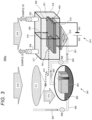
- FIG. 2 is a schematic view of a photocatalyst member provided in the photocatalyst decomposition system according to the invention.
- a porous material 100 shown in FIG. 1 is a nanoporous material having a pore 102 of several um to several tens of um in a base material 101.
- a photocatalyst member 200 in the invention is provided with a photocatalyst layer 201 on a surface of the nanoporous material shown in FIG. 1 .
- a gas-like or gaseous substance is converted into another gas or substance by a photocatalytic reaction with light from a light source.
- the photocatalyst decomposition system converts a liquid phase containing a decomposition object into a gas phase (vapor) and brings the gas phase into contact with the photocatalyst member to decompose the decomposition object.
- a surface area of a photocatalytic reaction portion is increased, and further, a generated gas phase is released without remaining in the photocatalytic reaction portion.
- the photocatalyst member provided in the photocatalyst decomposition system according to the invention can decompose not only a gas phase but also a liquid phase.
- the base material 101 is a material that transmits light having a wavelength of at least visible light or ultraviolet light, and is preferably a material having a three-dimensional block structure having a porous or reticular fiber material as a skeleton.
- the material of the base material 101 preferably contains SiO 2 , Al 2 O 3 , TiO 2 , MgO, ZnO, CaCO 3 , CaO, a transparent carbon nanotube (CNT), or SnO.
- the photocatalyst layer 201 is not particularly limited, and for example, at least one of substances listed in the following (1) to (4) can be preferably used, or a combination of these substances may be used.
- Particles of a co-catalyst material that promotes the photocatalytic reaction may be supported on, or a thin film of the co-catalyst material may be provided on at least a part of the photocatalyst layer 201.
- the co-catalyst material is not particularly limited, and WO 3 , Rh/Cr 2 O 3 , Ag, Rh/SrTiO 3 , Pt, CoO, Co 3 O 4 , IrO 2 , PtO 2 , phosphorus, NiO, RuO 2 , AgSbO 3 , or ZnRhO x can be preferably used.
- a porosity (a volume ratio of the pore 102) of the photocatalyst member 200 is preferably 40% to 95% (40% or more and 95% or less). When the porosity is less than 40%, it is difficult to provide a sufficient surface area for the reaction of the photocatalyst layer 201. When the porosity exceeds 95%, it is difficult to secure strength of the photocatalyst member 200.
- the base material 101 preferably has a pore width of 10 um to 500 um.
- a surface area in the pore of the nanoporous material is 10 m 2 /g to 1000 m 2 /g (general value).
- a pore size and material can have various variations (porous glass specific gravity: 1 g/cm 2 to 2 g/cm 2 ).
- the pore 102 in the porous material as the base material 101 can be subjected to immersion, vacuum impregnation, vacuum aeration, or spin coating with respect to a liquid obtained by mixing a liquid (MOD material) containing a metal organic compound that contains the material of the photocatalyst layer 201 and a metal complex solution or a metal-oxide colloid solution produced by a sol-gel method, followed by sintering to produce an object with photocatalyst coating and modification on an inner surface of the pore.
- Various photocatalyst materials can be synthesized by selectively using the above method.
- a coating film is continuous up to an internal structure, thereby enabling electrical conduction from the surface.
- an outer surface of the photocatalyst member 200 and a surface of the pore 102 in the photocatalyst member 200 have electrical continuity.
- a transparent conductive thin film layer may be provided on a surface of the photocatalyst layer 201 or between the base material 101 and the photocatalyst layer 201, and the photocatalyst layer 201 and the transparent conductive thin film layer may be electrically connected to each other.
- FIG. 3 schematically shows a photocatalyst decomposition system according to Embodiment 1.
- a photocatalyst decomposition system 300a according to the present embodiment includes a photocatalyst member 320 using the above-described photocatalyst member 200 and a vapor supply apparatus 301 configured to supply vapor to the photocatalyst member 320.
- the photocatalyst decomposition system supplies a light source (for example, sunlight 310) to the vapor supply apparatus 301 and the photocatalyst member 320 by light supply apparatuses.
- the photocatalyst decomposition system 300a comprises a housing configured to accommodate the photocatalyst member 320.
- a transparent window, a lens, or an optical path is provided in the housing, and the sunlight 310 is emitted to the photocatalyst member 320 via the transparent window, the lens, or the optical path. It is preferable that ultraviolet to visible light 311 obtained by spectroscopy and collection of the sunlight 310 outside the housing is introduced into the housing, supplied and emitted to the photocatalyst member 320 through an optical fiber 313, and infrared light 312 obtained by spectroscopy and collection of the sunlight 310 is supplied to the vapor supply apparatus 301, whereby each apparatus can function efficiently.
- a liquid phase (for example, water) 303 containing a decomposition object which is supplied through a liquid phase (water) supply pipe 306, is heated using the sunlight 310 by a vapor generation member 304 provided in a vapor generation container 302 to generate vapor 305.
- the generated vapor is supplied to a photocatalyst decomposition apparatus 314 via a vapor transfer pipe 307.
- the supplied vapor 305 is supplied to the photocatalyst member 320 via a vapor introduction portion 315 and a vapor discharge portion 318.
- the photocatalyst member 320 is divided into at least two photocatalyst members 401 and 402 by a separation film 319 formed by a proton conductive film, and electrodes 322 and 323 as voltage application apparatuses are connected to the at least two photocatalyst members 401 and 402, respectively, so that a potential can be adjusted. Furthermore, a gas or water vapor is supplied to the at least two photocatalyst members 401 and 402, respectively. A generated substance can be separated by adjusting the potential by the electrodes 322 and 323.
- Generated gases 324 and 325 generated by decomposing the vapor 305 by the photocatalyst member 320 are discharged to the outside.
- the vapor 305 is water
- oxygen (O 2 ), hydrogen (H 2 ), and water vapor (H 2 O) are discharged as the generated gas.
- the decomposition object is not limited to water and can also be carbon dioxide (CO 2 ), nitrogen oxide (NO x ), or methane (CH 3 ).
- a gas phase generated by decomposition by the photocatalyst member 320 is collected by a collection apparatus.
- the decomposition object contained in the liquid phase can be decomposed efficiently by the photocatalyst after being converted into the gas phase by using natural energy such as sunlight. Since the photocatalyst member 320 used for decomposition by the photocatalyst has a reaction structure (which is porous) through which vapor can pass, a larger surface area can be used in a three-dimensional space.
- the decomposition reaction by the photocatalyst can be controlled.
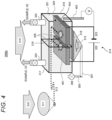
- FIG. 4 schematically shows a photocatalyst decomposition system 300b according to Embodiment 2.
- FIG. 4 mainly shows a configuration of the photocatalyst decomposition apparatus 314 constituting the photocatalyst decomposition system 300b.
- the photocatalyst decomposition system 300b according to the present embodiment is different from the photocatalyst decomposition system 300a according to Embodiment 1 in that a reference electrode 403 is provided. Accordingly, a potential of the electrodes 322 and 323 can be controlled.
- As the reference electrode 403, Ag/AgCl can be used.
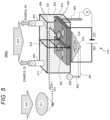
- FIG. 5 schematically shows a photocatalyst decomposition system 300c according to Embodiment 3.
- FIG. 5 mainly shows a configuration of the photocatalyst decomposition apparatus 314 constituting the photocatalyst decomposition system 300c.
- the photocatalyst decomposition system 300c according to the present embodiment is different from the photocatalyst decomposition system 300b according to Embodiment 2 in that the photocatalyst member 320 is in direct contact with the vapor discharge portion 318. With such a configuration, the vapor 305 can be more efficiently supplied to the photocatalyst member 320.
- FIG. 6 schematically shows a photocatalyst decomposition system 300d according to Embodiment 4.
- FIG. 6 mainly shows a configuration of the photocatalyst decomposition apparatus 314 constituting the photocatalyst decomposition system 300d.
- the photocatalyst decomposition system 300d according to the present embodiment is different from the photocatalyst decomposition system 300b according to Embodiment 2 in that a conduction terminal 601 is provided.
- a carrier can be exchanged between the electrodes 322 and 323, and the photocatalytic decomposition reaction can be controlled more precisely to perform reaction efficiently.
- FIG. 7 schematically shows a photocatalyst decomposition system 300e according to Embodiment 5.
- FIG. 7 mainly shows the photocatalyst decomposition apparatus 314 of the photocatalyst decomposition system 300e.
- the photocatalyst decomposition system 300e according to the present embodiment is different from the photocatalyst decomposition system 300b according to Embodiment 2 in that the photocatalyst member 320 is in contact with a liquid phase 701.
- the liquid phase can be directly supplied to the photocatalyst member 320, and the liquid phase 701 can be efficiently subjected to a reaction simultaneously with decomposition of the gas phase 305.
- FIG. 8 schematically shows a photocatalyst decomposition system 300f according to Embodiment 6.
- FIG. 8 mainly shows the photocatalyst decomposition apparatus 314 constituting the photocatalyst decomposition system 300f.
- the photocatalyst decomposition system 300f according to the present embodiment is different from the photocatalyst decomposition system 300b according to Embodiment 2 in that the photocatalyst member 320 is provided with co-catalyst-attached electrodes 404 and 405. With such a configuration, the photocatalyst member 320 can be efficiently subjected to a reaction.
- a photocatalyst decomposition apparatus that can supply a gas phase containing a substance to be decomposed by a photocatalyst and that can perform decomposition of the substance more efficiently than in the related art.
- the invention is not limited to the above-described embodiments, and includes various modifications.
- the embodiments described above have been described in detail to facilitate understanding of the invention, and the invention is not necessarily limited to those including all the configurations described above.
- a part of the configuration of one embodiment can be replaced with the configuration of another embodiment, and the configuration of another embodiment can be added to the configuration of one embodiment.
- a part of the configuration of each embodiment may be added to, deleted from, or replaced with another configuration.
Landscapes
- Chemical & Material Sciences (AREA)
- Organic Chemistry (AREA)
- Engineering & Computer Science (AREA)
- Chemical Kinetics & Catalysis (AREA)
- Materials Engineering (AREA)
- Inorganic Chemistry (AREA)
- Electrochemistry (AREA)
- Metallurgy (AREA)
- General Health & Medical Sciences (AREA)
- Combustion & Propulsion (AREA)
- Health & Medical Sciences (AREA)
- Catalysts (AREA)
- Oxygen, Ozone, And Oxides In General (AREA)
- Physical Or Chemical Processes And Apparatus (AREA)
- Electrodes For Compound Or Non-Metal Manufacture (AREA)
- Electrolytic Production Of Non-Metals, Compounds, Apparatuses Therefor (AREA)
Abstract
To provide a photocatalyst decomposition apparatus that can supply a liquid phase containing a substance to be decomposed by a photocatalyst and that can perform decomposition of the substance more efficiently than in the related art. A photocatalyst decomposition system according to the invention includes: a gas phase generation apparatus configured to convert a liquid phase containing a decomposition object into a gas phase; and a photocatalyst member configured to come into contact with the gas phase to decompose the decomposition object by light from a light source. The photocatalyst member includes a base material formed of a porous material and a photocatalyst layer provided on a surface of the base material.
Description
- The present invention relates to a photocatalyst decomposition system.
- A technique for decomposing water with sunlight and generating hydrogen with high efficiency is a storable energy carrier production technique having a low cost without discharging CO2 and is expected to be applied to a renewable energy service and an environmental service such as hydrogen power generation and a hydrogen automobile that contributes to fossil fuel elimination.
- Further, if a photocatalyst technique for decomposing a chemical substance having a large environmental influence is developed and becomes a technique that can use sunlight with high efficiency, the technique can be applied to production of a useful material by decomposing CO2 and methane discarded in not only water but also atmosphere, and NOx or a nitrate salt flowing into a water source from soil. Reduction of CO2 and methane contributes to inhibition of global warming, and NOx or a nitrate salt flowing into a water source from soil contributes to biodiversity through water or atmosphere. By not only decomposing but also converting such substances to a high-value substance such as alcohol or formic acid, such a technique is expected to be expanded as an industry with recycling-oriented PF through artificial photosynthesis as a substance generation system.
- An example of such a technique is disclosed in PTL 1. PTL 1 discloses a water photolysis apparatus including a casing 1 that includes a light transmission window 12 configured to transmit sunlight L, and a photolysis layer 5 provided on the casing 1. There is disclosed a configuration in which the photolysis apparatus is provided in a state of floating on a water layer 9, water vapor is evaporated from the water layer 9 due to irradiation with sunlight L, the water vapor is introduced into the photolysis layer 5, photocatalyst particles 52 are excited by the sunlight L in the photolysis layer 5, and the introduced water vapor is decomposed into hydrogen and oxygen. According to the configuration in PTL 1, it is possible to provide a water photolysis apparatus that can more efficiently obtain hydrogen and oxygen by inhibiting a reverse reaction and that can further promote photolysis of water by effectively using solar energy.
- PTL 1:
WO 2004/085306 - In the related art, in a configuration of an apparatus for decomposing a liquid phase by using a photocatalyst, light is emitted to a photocatalyst in a state in which the photocatalyst is charged in water in a form of a powder or a thin film to decompose water. A gas obtained by decomposition is generated as air bubbles on a surface of the photocatalyst, a certain amount of the gas is desorbed into water and collected, and there is a portion covered with the generated air bubbles on the surface of the photocatalyst. Accordingly, a contact area between a catalyst and water is reduced, resulting in saturation or reduction of a reaction rate, and thus an object is to eliminate such a problem and maintain a high reaction rate.
- As described above, since air bubbles or the like in a liquid phase may cause a reaction rate saturation or reduction, it is important to improve efficiency of the reaction by allowing the photocatalyst to react in a state of being charged in a gas phase to inhibit generation of air bubbles and to increase a contact surface area between the gas phase and the photocatalyst. In PTL 1 described above, the photocatalyst is supported in a state of being dispersed in a powder form on a porous material, it is difficult to form electrical continuity, and it is difficult to improve efficiency of the reaction by using an electrode or the like.
- In view of the above circumstances, an object of the invention is to provide a photocatalyst decomposition system that can supply a gas phase containing a substance to be decomposed by a photocatalyst and that can perform decomposition of the substance more efficiently than in the related art.
- According to an aspect of the invention for solving the above problem, a photocatalyst decomposition system includes: a gas phase generation apparatus configured to convert a liquid phase containing a decomposition object into a gas phase; and/or a photocatalyst member configured to come into contact with the gas phase to decompose the decomposition object by light from a light source and generate a gas phase. The photocatalyst member includes a base material formed of a porous material and a photocatalyst layer provided on a surface of the base material.
- A more specific configuration of the invention is described in claims.
- According to the invention, it is possible to provide a photocatalyst decomposition system that can supply a gas phase containing a substance to be decomposed by a photocatalyst and that can perform decomposition of the substance more efficiently than in the related art.
- Objects, configurations, and effects other than those described above will be clarified by the following description of embodiments. It is noted that the dependencies of the appended claims may be changed and all other possible claim combinations are also encompassed by the present disclosure except claim combinations which would lead to contradictions of the claimed subject-matter.
-
-
FIG. 1 is a schematic view of a porous material; -
FIG. 2 is a schematic view of a photocatalyst member provided in a photocatalyst decomposition apparatus according to the invention; -
FIG. 3 schematically shows a photocatalyst decomposition system according to Embodiment 1; -
FIG. 4 schematically shows a photocatalyst decomposition system according to Embodiment 2; -
FIG. 5 schematically shows a photocatalyst decomposition system according to Embodiment 3; -
FIG. 6 schematically shows a photocatalyst decomposition system according to Embodiment 4; -
FIG. 7 schematically shows a photocatalyst decomposition system according to Embodiment 5; and -
FIG. 8 schematically shows a photocatalyst decomposition system according to Embodiment 6. - Hereinafter, a configuration of the invention will be described in detail with reference to the drawings.
- As described above, a photocatalyst decomposition system according to the invention includes: a gas phase generation apparatus configured to convert a liquid phase containing a decomposition object into a gas phase; and a photocatalyst member configured to come into contact with the gas phase to decompose the decomposition object by light from a light source and generate a gas phase. The photocatalyst member includes a base material formed of a porous material and a photocatalyst layer provided on a surface of the base material. First, the photocatalyst member will be described.
FIG. 1 is a schematic view of a porous material.FIG. 2 is a schematic view of a photocatalyst member provided in the photocatalyst decomposition system according to the invention. Aporous material 100 shown inFIG. 1 is a nanoporous material having apore 102 of several um to several tens of um in abase material 101. Aphotocatalyst member 200 in the invention, as shown inFIG. 2 , is provided with aphotocatalyst layer 201 on a surface of the nanoporous material shown inFIG. 1 . In the invention, by using such aphotocatalyst member 200, a gas-like or gaseous substance is converted into another gas or substance by a photocatalytic reaction with light from a light source. - The photocatalyst decomposition system according to the invention converts a liquid phase containing a decomposition object into a gas phase (vapor) and brings the gas phase into contact with the photocatalyst member to decompose the decomposition object. By providing the
photocatalyst layer 201 on thebase material 101 formed of the porous material as described above, a surface area of a photocatalytic reaction portion is increased, and further, a generated gas phase is released without remaining in the photocatalytic reaction portion. Accordingly, it is possible to prevent a phenomenon in which a surface of thephotocatalyst layer 201 is covered with air bubbles generated when the liquid phase is brought into contact with the photocatalyst member, and to prevent a decrease in a contact area between the gas phase and thephotocatalyst layer 201. - The photocatalyst member provided in the photocatalyst decomposition system according to the invention can decompose not only a gas phase but also a liquid phase.
- The
base material 101 is a material that transmits light having a wavelength of at least visible light or ultraviolet light, and is preferably a material having a three-dimensional block structure having a porous or reticular fiber material as a skeleton. The material of thebase material 101 preferably contains SiO2, Al2O3, TiO2, MgO, ZnO, CaCO3, CaO, a transparent carbon nanotube (CNT), or SnO. - The
photocatalyst layer 201 is not particularly limited, and for example, at least one of substances listed in the following (1) to (4) can be preferably used, or a combination of these substances may be used. - (1) BiVO4 doped with Rh or black phosphorus, or BiVO4,
- (2) SrTiO3 doped with Rh, Ir, La, or Al, or SrTiO3,
- (3) LaON, TiO2, GaP, SnNb2O6, or NaTaO3 doped with La, or NaTaO3, and
- (4) TaON, LaTiO2N, TaON, Ta3N5, SrTa2ON, LaTa2ON, ZnRh2O4, Sm2Ti2O5S2, Y2Ti2O2S5, g-C3N4, Ga3N4, Cu0.25Ag0.25In0.25ZnS2, or CuAgZnSnS4
- Particles of a co-catalyst material that promotes the photocatalytic reaction may be supported on, or a thin film of the co-catalyst material may be provided on at least a part of the
photocatalyst layer 201. The co-catalyst material is not particularly limited, and WO3, Rh/Cr2O3, Ag, Rh/SrTiO3, Pt, CoO, Co3O4, IrO2, PtO2, phosphorus, NiO, RuO2, AgSbO3, or ZnRhOx can be preferably used. - A porosity (a volume ratio of the pore 102) of the
photocatalyst member 200 is preferably 40% to 95% (40% or more and 95% or less). When the porosity is less than 40%, it is difficult to provide a sufficient surface area for the reaction of thephotocatalyst layer 201. When the porosity exceeds 95%, it is difficult to secure strength of thephotocatalyst member 200. Thebase material 101 preferably has a pore width of 10 um to 500 um. - A surface area in the pore of the nanoporous material is 10 m2/g to 1000 m2/g (general value). A pore size and material can have various variations (porous glass specific gravity: 1 g/cm2 to 2 g/cm2).
- As a method for producing the
photocatalyst member 200, thepore 102 in the porous material as thebase material 101 can be subjected to immersion, vacuum impregnation, vacuum aeration, or spin coating with respect to a liquid obtained by mixing a liquid (MOD material) containing a metal organic compound that contains the material of thephotocatalyst layer 201 and a metal complex solution or a metal-oxide colloid solution produced by a sol-gel method, followed by sintering to produce an object with photocatalyst coating and modification on an inner surface of the pore. Various photocatalyst materials can be synthesized by selectively using the above method. A coating film is continuous up to an internal structure, thereby enabling electrical conduction from the surface. In other words, an outer surface of thephotocatalyst member 200 and a surface of thepore 102 in thephotocatalyst member 200 have electrical continuity. A transparent conductive thin film layer may be provided on a surface of thephotocatalyst layer 201 or between thebase material 101 and thephotocatalyst layer 201, and thephotocatalyst layer 201 and the transparent conductive thin film layer may be electrically connected to each other. - Hereinafter, the photocatalyst decomposition system according to the invention including the above-described photocatalyst member will be described in detail.
-
FIG. 3 schematically shows a photocatalyst decomposition system according to Embodiment 1. As shown inFIG. 3 , aphotocatalyst decomposition system 300a according to the present embodiment includes aphotocatalyst member 320 using the above-describedphotocatalyst member 200 and avapor supply apparatus 301 configured to supply vapor to thephotocatalyst member 320. The photocatalyst decomposition system supplies a light source (for example, sunlight 310) to thevapor supply apparatus 301 and thephotocatalyst member 320 by light supply apparatuses. Thephotocatalyst decomposition system 300a comprises a housing configured to accommodate thephotocatalyst member 320. A transparent window, a lens, or an optical path is provided in the housing, and thesunlight 310 is emitted to thephotocatalyst member 320 via the transparent window, the lens, or the optical path. It is preferable that ultraviolet tovisible light 311 obtained by spectroscopy and collection of thesunlight 310 outside the housing is introduced into the housing, supplied and emitted to thephotocatalyst member 320 through anoptical fiber 313, andinfrared light 312 obtained by spectroscopy and collection of thesunlight 310 is supplied to thevapor supply apparatus 301, whereby each apparatus can function efficiently. - In the
vapor supply apparatus 301, a liquid phase (for example, water) 303 containing a decomposition object, which is supplied through a liquid phase (water)supply pipe 306, is heated using thesunlight 310 by avapor generation member 304 provided in avapor generation container 302 to generatevapor 305. The generated vapor is supplied to aphotocatalyst decomposition apparatus 314 via avapor transfer pipe 307. - In the
photocatalyst decomposition apparatus 314, the suppliedvapor 305 is supplied to thephotocatalyst member 320 via avapor introduction portion 315 and avapor discharge portion 318. - The
photocatalyst member 320 is divided into at least twophotocatalyst members separation film 319 formed by a proton conductive film, andelectrodes photocatalyst members photocatalyst members electrodes - Generated
gases vapor 305 by thephotocatalyst member 320 are discharged to the outside. For example, when thevapor 305 is water, oxygen (O2), hydrogen (H2), and water vapor (H2O) are discharged as the generated gas. The decomposition object is not limited to water and can also be carbon dioxide (CO2), nitrogen oxide (NOx), or methane (CH3). A gas phase generated by decomposition by thephotocatalyst member 320 is collected by a collection apparatus. - According to the above-described
photocatalyst decomposition system 300a in the invention, the decomposition object contained in the liquid phase can be decomposed efficiently by the photocatalyst after being converted into the gas phase by using natural energy such as sunlight. Since thephotocatalyst member 320 used for decomposition by the photocatalyst has a reaction structure (which is porous) through which vapor can pass, a larger surface area can be used in a three-dimensional space. - Further, by providing the
electrodes -
FIG. 4 schematically shows aphotocatalyst decomposition system 300b according to Embodiment 2.FIG. 4 mainly shows a configuration of thephotocatalyst decomposition apparatus 314 constituting thephotocatalyst decomposition system 300b. Thephotocatalyst decomposition system 300b according to the present embodiment is different from thephotocatalyst decomposition system 300a according to Embodiment 1 in that areference electrode 403 is provided. Accordingly, a potential of theelectrodes reference electrode 403, Ag/AgCl can be used. -
FIG. 5 schematically shows aphotocatalyst decomposition system 300c according to Embodiment 3.FIG. 5 mainly shows a configuration of thephotocatalyst decomposition apparatus 314 constituting thephotocatalyst decomposition system 300c. Thephotocatalyst decomposition system 300c according to the present embodiment is different from thephotocatalyst decomposition system 300b according to Embodiment 2 in that thephotocatalyst member 320 is in direct contact with thevapor discharge portion 318. With such a configuration, thevapor 305 can be more efficiently supplied to thephotocatalyst member 320. -
FIG. 6 schematically shows aphotocatalyst decomposition system 300d according to Embodiment 4.FIG. 6 mainly shows a configuration of thephotocatalyst decomposition apparatus 314 constituting thephotocatalyst decomposition system 300d. Thephotocatalyst decomposition system 300d according to the present embodiment is different from thephotocatalyst decomposition system 300b according to Embodiment 2 in that aconduction terminal 601 is provided. With such a configuration, a carrier can be exchanged between theelectrodes -
FIG. 7 schematically shows aphotocatalyst decomposition system 300e according to Embodiment 5.FIG. 7 mainly shows thephotocatalyst decomposition apparatus 314 of thephotocatalyst decomposition system 300e. Thephotocatalyst decomposition system 300e according to the present embodiment is different from thephotocatalyst decomposition system 300b according to Embodiment 2 in that thephotocatalyst member 320 is in contact with aliquid phase 701. With such a configuration, the liquid phase can be directly supplied to thephotocatalyst member 320, and theliquid phase 701 can be efficiently subjected to a reaction simultaneously with decomposition of thegas phase 305. -
FIG. 8 schematically shows aphotocatalyst decomposition system 300f according to Embodiment 6.FIG. 8 mainly shows thephotocatalyst decomposition apparatus 314 constituting thephotocatalyst decomposition system 300f. Thephotocatalyst decomposition system 300f according to the present embodiment is different from thephotocatalyst decomposition system 300b according to Embodiment 2 in that thephotocatalyst member 320 is provided with co-catalyst-attachedelectrodes photocatalyst member 320 can be efficiently subjected to a reaction. - As described above, according to the invention, it is possible to provide a photocatalyst decomposition apparatus that can supply a gas phase containing a substance to be decomposed by a photocatalyst and that can perform decomposition of the substance more efficiently than in the related art.
- The invention is not limited to the above-described embodiments, and includes various modifications. For example, the embodiments described above have been described in detail to facilitate understanding of the invention, and the invention is not necessarily limited to those including all the configurations described above. In addition, a part of the configuration of one embodiment can be replaced with the configuration of another embodiment, and the configuration of another embodiment can be added to the configuration of one embodiment. In addition, a part of the configuration of each embodiment may be added to, deleted from, or replaced with another configuration.
Claims (16)
- A photocatalyst decomposition system comprising:a gas phase generation apparatus configured to convert a liquid phase containing a decomposition object into a gas phase; anda photocatalyst member configured to come into contact with the gas phase to decompose the decomposition object by light from a light source, whereinthe photocatalyst member includes a base material formed of a porous material and a photocatalyst layer provided on a surface of the base material.
- The photocatalyst decomposition system according to claim 1, wherein
the photocatalyst member is also configured to come into contact with the liquid phase to decompose the decomposition object. - The photocatalyst decomposition system according to claim 1 or 2, wherein
an outer surface of the photocatalyst member and a surface of a pore in the photocatalyst member have electrical continuity. - The photocatalyst decomposition system according to claim 1 or 2, wherein
a transparent conductive thin film layer is provided on a surface of the photocatalyst layer or between the base material and the photocatalyst layer, and the photocatalyst layer and the transparent conductive thin film layer are electrically connected to each other. - The photocatalyst decomposition system according to claim 1 or 2, further comprising:
a configuration configured to adjust a potential by at least one pair of electrodes in contact with the photocatalyst member. - The photocatalyst decomposition system according to claim 1 or 2, further comprising:at least two of the photocatalyst members;a proton conductive film provided between the at least two photocatalyst members; anda pair of electrodes connected to the at least two photocatalyst members, respectively, whereina potential is adjustable by the electrodes, anda gas or water vapor is supplied to the at least two photocatalyst members, respectively.
- The photocatalyst decomposition system according to claim 5, wherein
a generated substance is separated by adjusting the potential by the electrode. - The photocatalyst decomposition system according to claim 1 or 2, further comprising:a housing configured to accommodate the photocatalyst member, whereinthe light source is sunlight, anda transparent window, a lens, or an optical path is provided in the housing, and the sunlight is emitted to the photocatalyst member via the transparent window, the lens, or the optical path.
- The photocatalyst decomposition system according to claim 8, wherein
light condensed outside the housing is introduced into the housing through an optical fiber and emitted to the photocatalyst member. - The photocatalyst decomposition system according to claim 1 or 2, wherein
the base material transmits light having a wavelength of at least visible light or ultraviolet light. - The photocatalyst decomposition system according to claim 1 or 2, wherein
the base material has a pore width of 10 um to 500 um and a porosity of 40% to 95%. - The photocatalyst decomposition system according to claim 1 or 2, wherein
the porous material forming the base material contains SiO2, Al2O3, TiO2, MgO, ZnO, CaCO3, CaO, SnO, or a transparent carbon nanotube. - The photocatalyst decomposition system according to claim 1 or 2, wherein
the photocatalyst layer is at least one of substances listed in the following (1) to (4):(1) BiVO4 doped with Rh or black phosphorus, or BiVO4,(2) SrTiO3 doped with Rh, Ir, La, or Al, or SrTiO3,(3) LaON, TiO2, GaP, SnNb2O6, or NaTaO3 doped with La, or NaTaO3, and(4) TaON, LaTiO2N, TaON, Ta3N5, SrTa2ON, LaTa2ON, ZnRh2O4, Sm2Ti2O5S2, Y2Ti2O2S5, g-C3N4, Ga3N4, Cu0.25Ag0.25In0.25ZnS2, or CuAgZnSnS4. - The photocatalyst decomposition system according to claim 1 or 2, wherein
particles of a co-catalyst material are supported on, or a thin film of the co-catalyst material is provided on at least a part of the photocatalyst layer. - The photocatalyst decomposition system according to claim 14, wherein
the co-catalyst material is WO3, Rh/Cr2O3, Ag, Rh/SrTiO3, Pt, CoO, Co3O4, IrO2, PtO2, phosphorus, NiO, RuO2, AgSbO3, or ZnRhOx. - The photocatalyst decomposition system according to claim 1 or 2, further comprising:a light supply apparatus configured to supply light to the photocatalyst member and the gas phase generation apparatus; anda collection apparatus configured to collect a gas phase generated by decomposition by the photocatalyst member.
Applications Claiming Priority (1)
| Application Number | Priority Date | Filing Date | Title |
|---|---|---|---|
| JP2022175972A JP2024066562A (en) | 2022-11-02 | 2022-11-02 | Photocatalytic decomposition system |
Publications (1)
| Publication Number | Publication Date |
|---|---|
| EP4364848A1 true EP4364848A1 (en) | 2024-05-08 |
Family
ID=88506572
Family Applications (1)
| Application Number | Title | Priority Date | Filing Date |
|---|---|---|---|
| EP23204828.0A Pending EP4364848A1 (en) | 2022-11-02 | 2023-10-20 | Photocatalyst decomposition system |
Country Status (3)
| Country | Link |
|---|---|
| US (1) | US20240139723A1 (en) |
| EP (1) | EP4364848A1 (en) |
| JP (1) | JP2024066562A (en) |
Families Citing this family (1)
| Publication number | Priority date | Publication date | Assignee | Title |
|---|---|---|---|---|
| CN116809102A (en) * | 2023-04-21 | 2023-09-29 | 中国民航大学 | Stannous oxide/carbon nitride visible light catalyst and preparation method and application thereof |
Citations (3)
| Publication number | Priority date | Publication date | Assignee | Title |
|---|---|---|---|---|
| WO2004085306A1 (en) * | 2003-03-26 | 2004-10-07 | Matsushita Electric Industrial Co. Ltd. | Apparatus for photolysis of water and method for photolysis of water |
| US20130256147A1 (en) * | 2012-04-02 | 2013-10-03 | California Institute Of Technology | Solar fuels generator |
| US20160040303A1 (en) * | 2014-08-11 | 2016-02-11 | International Business Machines Corporation | Techniques for Photocatalytic Hydrogen Generation |
-
2022
- 2022-11-02 JP JP2022175972A patent/JP2024066562A/en active Pending
-
2023
- 2023-10-12 US US18/485,656 patent/US20240139723A1/en active Pending
- 2023-10-20 EP EP23204828.0A patent/EP4364848A1/en active Pending
Patent Citations (3)
| Publication number | Priority date | Publication date | Assignee | Title |
|---|---|---|---|---|
| WO2004085306A1 (en) * | 2003-03-26 | 2004-10-07 | Matsushita Electric Industrial Co. Ltd. | Apparatus for photolysis of water and method for photolysis of water |
| US20130256147A1 (en) * | 2012-04-02 | 2013-10-03 | California Institute Of Technology | Solar fuels generator |
| US20160040303A1 (en) * | 2014-08-11 | 2016-02-11 | International Business Machines Corporation | Techniques for Photocatalytic Hydrogen Generation |
Non-Patent Citations (1)
| Title |
|---|
| HAN HONGTAO ET AL: "Enhanced photocatalytic splitting of photothermally induced water vapor to evolve hydrogen", CHEMICAL ENGENEERING JOURNAL, ELSEVIER, AMSTERDAM, NL, vol. 450, 2 August 2022 (2022-08-02), XP087181621, ISSN: 1385-8947, [retrieved on 20220802], DOI: 10.1016/J.CEJ.2022.138419 * |
Also Published As
| Publication number | Publication date |
|---|---|
| US20240139723A1 (en) | 2024-05-02 |
| JP2024066562A (en) | 2024-05-16 |
Similar Documents
| Publication | Publication Date | Title |
|---|---|---|
| Deng et al. | High-efficiency electrochemical nitrate reduction to ammonia on a Co3O4 nanoarray catalyst with cobalt vacancies | |
| Wang et al. | Photocatalytic water oxidation on BiVO4 with the electrocatalyst as an oxidation cocatalyst: essential relations between electrocatalyst and photocatalyst | |
| Xu et al. | Fluorine-induced dual defects in cobalt phosphide nanosheets enhance hydrogen evolution reaction activity | |
| Chen et al. | Greatly facilitated two-electron electroreduction of oxygen into hydrogen peroxide over TiO2 by Mn doping | |
| Jiao et al. | Nanostructured cobalt and manganese oxide clusters as efficient water oxidation catalysts | |
| Yusuf et al. | Effect of the support on the photocatalytic water oxidation activity of cobalt oxide nanoclusters | |
| US8216432B2 (en) | Optimizing reactions in fuel cells and electrochemical reactions | |
| Liu et al. | Highly-active direct Z-scheme Si/TiO 2 photocatalyst for boosted CO 2 reduction into value-added methanol | |
| CN113061923B (en) | High-activity electrochemical self-doping TiO 2 Nanotube-based material, preparation and application thereof | |
| CN103974769A (en) | Electrocatalyst material and its manufacturing method | |
| Kunchala et al. | Irregularly shaped Mn2O3 nanostructures with high surface area for water oxidation | |
| WO2022032340A1 (en) | Catalyst | |
| Chen et al. | Lanthanide–titanium oxo cluster and BiVO4 Z-scheme photocatalyst sheets for carbon dioxide reduction | |
| Ping et al. | Fabrication of self-organized TiO2 nanotube arrays for photocatalytic reduction of CO2 | |
| EP4364848A1 (en) | Photocatalyst decomposition system | |
| Zahran et al. | Nickel sulfate as an influential precursor of amorphous high-valent Ni (III) oxides for efficient water oxidation in preparation via a mixed metal-imidazole casting method | |
| JP7028393B2 (en) | An co-catalyst for an oxygen-generating photocatalyst, an oxygen-generating photocatalyst carrying the co-catalyst, and a complex and a method for producing the complex. | |
| KR101814128B1 (en) | manufacturing method of hydrogen using liquid phase plasma and photocatalysts | |
| Ji et al. | Oxygen vacancies of CeO2 Nanospheres by Mn-doping: An efficient electrocatalyst for N2 reduction under ambient conditions | |
| US20140154597A1 (en) | Fuel Cells Based on Precise Energy Separation | |
| JP3697591B2 (en) | Thin film photocatalytic chemical converter | |
| EP4225494A1 (en) | Metal organic framework and use thereof for generating h2 | |
| Wang et al. | Phase and Composition Engineering of Mn-Doped TiO2 for Hydrogen Peroxide Synthesis through Ion-Mediated Water Oxidation | |
| Zhang et al. | Anodic Water Oxidation to H2O2 on Ov-Rich ZnO Nanoparticles for Degradation of Tetracycline | |
| Iriawan et al. | Assessing the Activity of Transition Metal Oxides for the Electrochemical N2 Oxidation to Nitrate |
Legal Events
| Date | Code | Title | Description |
|---|---|---|---|
| PUAI | Public reference made under article 153(3) epc to a published international application that has entered the european phase |
Free format text: ORIGINAL CODE: 0009012 |
|
| STAA | Information on the status of an ep patent application or granted ep patent |
Free format text: STATUS: REQUEST FOR EXAMINATION WAS MADE |
|
| 17P | Request for examination filed |
Effective date: 20231229 |
|
| AK | Designated contracting states |
Kind code of ref document: A1 Designated state(s): AL AT BE BG CH CY CZ DE DK EE ES FI FR GB GR HR HU IE IS IT LI LT LU LV MC ME MK MT NL NO PL PT RO RS SE SI SK SM TR |