EP4364672A1 - Catheter for diagnostic imaging - Google Patents
Catheter for diagnostic imaging Download PDFInfo
- Publication number
- EP4364672A1 EP4364672A1 EP22849600.6A EP22849600A EP4364672A1 EP 4364672 A1 EP4364672 A1 EP 4364672A1 EP 22849600 A EP22849600 A EP 22849600A EP 4364672 A1 EP4364672 A1 EP 4364672A1
- Authority
- EP
- European Patent Office
- Prior art keywords
- tube
- support tube
- image diagnosis
- drive shaft
- inner tube
- Prior art date
- Legal status (The legal status is an assumption and is not a legal conclusion. Google has not performed a legal analysis and makes no representation as to the accuracy of the status listed.)
- Pending
Links
- 238000002059 diagnostic imaging Methods 0.000 title 1
- 238000003745 diagnosis Methods 0.000 claims abstract description 58
- 230000002093 peripheral effect Effects 0.000 description 25
- 230000037452 priming Effects 0.000 description 25
- 244000208734 Pisonia aculeata Species 0.000 description 24
- 230000003287 optical effect Effects 0.000 description 14
- 239000000243 solution Substances 0.000 description 14
- 230000004048 modification Effects 0.000 description 12
- 238000012986 modification Methods 0.000 description 12
- 125000006850 spacer group Chemical group 0.000 description 10
- 238000002604 ultrasonography Methods 0.000 description 8
- 238000004891 communication Methods 0.000 description 7
- 238000003384 imaging method Methods 0.000 description 7
- 238000003780 insertion Methods 0.000 description 6
- 230000037431 insertion Effects 0.000 description 6
- 229910052751 metal Inorganic materials 0.000 description 6
- 239000002184 metal Substances 0.000 description 6
- 238000012014 optical coherence tomography Methods 0.000 description 6
- 230000003014 reinforcing effect Effects 0.000 description 6
- 238000007789 sealing Methods 0.000 description 6
- 238000002608 intravascular ultrasound Methods 0.000 description 5
- 230000033001 locomotion Effects 0.000 description 5
- 238000003466 welding Methods 0.000 description 5
- 239000000853 adhesive Substances 0.000 description 4
- 230000001070 adhesive effect Effects 0.000 description 4
- 239000000463 material Substances 0.000 description 4
- 230000000694 effects Effects 0.000 description 3
- 238000002347 injection Methods 0.000 description 3
- 239000007924 injection Substances 0.000 description 3
- 239000003550 marker Substances 0.000 description 3
- 229920003002 synthetic resin Polymers 0.000 description 3
- 239000000057 synthetic resin Substances 0.000 description 3
- PPBRXRYQALVLMV-UHFFFAOYSA-N Styrene Chemical compound C=CC1=CC=CC=C1 PPBRXRYQALVLMV-UHFFFAOYSA-N 0.000 description 2
- HZEWFHLRYVTOIW-UHFFFAOYSA-N [Ti].[Ni] Chemical compound [Ti].[Ni] HZEWFHLRYVTOIW-UHFFFAOYSA-N 0.000 description 2
- 229910045601 alloy Inorganic materials 0.000 description 2
- 239000000956 alloy Substances 0.000 description 2
- 238000006243 chemical reaction Methods 0.000 description 2
- 229910001000 nickel titanium Inorganic materials 0.000 description 2
- 239000002356 single layer Substances 0.000 description 2
- 239000004709 Chlorinated polyethylene Substances 0.000 description 1
- 239000004952 Polyamide Substances 0.000 description 1
- 239000005062 Polybutadiene Substances 0.000 description 1
- 239000004642 Polyimide Substances 0.000 description 1
- 210000004204 blood vessel Anatomy 0.000 description 1
- 239000000919 ceramic Substances 0.000 description 1
- 210000004351 coronary vessel Anatomy 0.000 description 1
- 238000007599 discharging Methods 0.000 description 1
- 230000009977 dual effect Effects 0.000 description 1
- 230000002708 enhancing effect Effects 0.000 description 1
- 238000001125 extrusion Methods 0.000 description 1
- 229920001973 fluoroelastomer Polymers 0.000 description 1
- 229910052737 gold Inorganic materials 0.000 description 1
- 238000001746 injection moulding Methods 0.000 description 1
- 239000013307 optical fiber Substances 0.000 description 1
- 230000035699 permeability Effects 0.000 description 1
- 229910052697 platinum Inorganic materials 0.000 description 1
- 229920002647 polyamide Polymers 0.000 description 1
- 229920002857 polybutadiene Polymers 0.000 description 1
- 229920000728 polyester Polymers 0.000 description 1
- 229920001721 polyimide Polymers 0.000 description 1
- 229920001195 polyisoprene Polymers 0.000 description 1
- 229920000642 polymer Polymers 0.000 description 1
- 229920002959 polymer blend Polymers 0.000 description 1
- 229920000098 polyolefin Polymers 0.000 description 1
- 229920002635 polyurethane Polymers 0.000 description 1
- 239000004814 polyurethane Substances 0.000 description 1
- 239000000843 powder Substances 0.000 description 1
- 230000001737 promoting effect Effects 0.000 description 1
- 239000010453 quartz Substances 0.000 description 1
- VYPSYNLAJGMNEJ-UHFFFAOYSA-N silicon dioxide Inorganic materials O=[Si]=O VYPSYNLAJGMNEJ-UHFFFAOYSA-N 0.000 description 1
- 239000010935 stainless steel Substances 0.000 description 1
- 229910001220 stainless steel Inorganic materials 0.000 description 1
- 229920002725 thermoplastic elastomer Polymers 0.000 description 1
- 230000002792 vascular Effects 0.000 description 1
- 238000004804 winding Methods 0.000 description 1
Images







Classifications
-
- A—HUMAN NECESSITIES
- A61—MEDICAL OR VETERINARY SCIENCE; HYGIENE
- A61B—DIAGNOSIS; SURGERY; IDENTIFICATION
- A61B8/00—Diagnosis using ultrasonic, sonic or infrasonic waves
- A61B8/08—Clinical applications
- A61B8/0891—Clinical applications for diagnosis of blood vessels
-
- A—HUMAN NECESSITIES
- A61—MEDICAL OR VETERINARY SCIENCE; HYGIENE
- A61B—DIAGNOSIS; SURGERY; IDENTIFICATION
- A61B5/00—Measuring for diagnostic purposes; Identification of persons
- A61B5/0033—Features or image-related aspects of imaging apparatus, e.g. for MRI, optical tomography or impedance tomography apparatus; Arrangements of imaging apparatus in a room
- A61B5/0035—Features or image-related aspects of imaging apparatus, e.g. for MRI, optical tomography or impedance tomography apparatus; Arrangements of imaging apparatus in a room adapted for acquisition of images from more than one imaging mode, e.g. combining MRI and optical tomography
-
- A—HUMAN NECESSITIES
- A61—MEDICAL OR VETERINARY SCIENCE; HYGIENE
- A61B—DIAGNOSIS; SURGERY; IDENTIFICATION
- A61B5/00—Measuring for diagnostic purposes; Identification of persons
- A61B5/0059—Measuring for diagnostic purposes; Identification of persons using light, e.g. diagnosis by transillumination, diascopy, fluorescence
- A61B5/0062—Arrangements for scanning
- A61B5/0066—Optical coherence imaging
-
- A—HUMAN NECESSITIES
- A61—MEDICAL OR VETERINARY SCIENCE; HYGIENE
- A61B—DIAGNOSIS; SURGERY; IDENTIFICATION
- A61B5/00—Measuring for diagnostic purposes; Identification of persons
- A61B5/0059—Measuring for diagnostic purposes; Identification of persons using light, e.g. diagnosis by transillumination, diascopy, fluorescence
- A61B5/0082—Measuring for diagnostic purposes; Identification of persons using light, e.g. diagnosis by transillumination, diascopy, fluorescence adapted for particular medical purposes
- A61B5/0084—Measuring for diagnostic purposes; Identification of persons using light, e.g. diagnosis by transillumination, diascopy, fluorescence adapted for particular medical purposes for introduction into the body, e.g. by catheters
-
- A—HUMAN NECESSITIES
- A61—MEDICAL OR VETERINARY SCIENCE; HYGIENE
- A61B—DIAGNOSIS; SURGERY; IDENTIFICATION
- A61B5/00—Measuring for diagnostic purposes; Identification of persons
- A61B5/68—Arrangements of detecting, measuring or recording means, e.g. sensors, in relation to patient
- A61B5/6846—Arrangements of detecting, measuring or recording means, e.g. sensors, in relation to patient specially adapted to be brought in contact with an internal body part, i.e. invasive
- A61B5/6847—Arrangements of detecting, measuring or recording means, e.g. sensors, in relation to patient specially adapted to be brought in contact with an internal body part, i.e. invasive mounted on an invasive device
- A61B5/6852—Catheters
-
- A—HUMAN NECESSITIES
- A61—MEDICAL OR VETERINARY SCIENCE; HYGIENE
- A61B—DIAGNOSIS; SURGERY; IDENTIFICATION
- A61B8/00—Diagnosis using ultrasonic, sonic or infrasonic waves
- A61B8/12—Diagnosis using ultrasonic, sonic or infrasonic waves in body cavities or body tracts, e.g. by using catheters
-
- A—HUMAN NECESSITIES
- A61—MEDICAL OR VETERINARY SCIENCE; HYGIENE
- A61B—DIAGNOSIS; SURGERY; IDENTIFICATION
- A61B8/00—Diagnosis using ultrasonic, sonic or infrasonic waves
- A61B8/44—Constructional features of the ultrasonic, sonic or infrasonic diagnostic device
- A61B8/4444—Constructional features of the ultrasonic, sonic or infrasonic diagnostic device related to the probe
- A61B8/445—Details of catheter construction
-
- A—HUMAN NECESSITIES
- A61—MEDICAL OR VETERINARY SCIENCE; HYGIENE
- A61B—DIAGNOSIS; SURGERY; IDENTIFICATION
- A61B8/00—Diagnosis using ultrasonic, sonic or infrasonic waves
- A61B8/44—Constructional features of the ultrasonic, sonic or infrasonic diagnostic device
- A61B8/4444—Constructional features of the ultrasonic, sonic or infrasonic diagnostic device related to the probe
- A61B8/4461—Features of the scanning mechanism, e.g. for moving the transducer within the housing of the probe
Definitions
- This disclosure relates to an image diagnosis catheter.
- An image diagnosis catheter typically has a pull-back mechanism on a side closer to a user's hand for changing a relative position between a sheath and a drive shaft in order to continuously monitor a cross section of a body cavity.
- the pull-back mechanism includes an outer tube and an inner tube that is disposed on the radially inner side of the outer tube and radially outer side of the drive shaft and is axially movable with the drive shaft and relative to the outer tube.
- JP 4672188 B1 discloses a pull-back mechanism in which a support tube axially movable with an outer tube is disposed on the radially outer side of a drive shaft and radially inner side of an inner tube so as not to buckle the drive shaft during push-forward operation.
- Patent Literature 1 US Pat. No. 4,672,188
- an object of this disclosure is to provide an image diagnosis catheter in which a drive shaft is hardly buckled not only inside an outer tube but also inside an inner tube during push-forward operation.
- an image diagnosis catheter includes: an outer tube; a first support tube disposed on the radially inner side of the outer tube; a drive shaft disposed on the radially inner side of the first support tube; an inner tube disposed on the radially inner side of the outer tube and radially outer side of the first support tube; and a second support tube disposed on the radially inner side of the inner tube and radially outer side of the drive shaft, being axially movable with the drive shaft and the inner tube and relative to the outer tube and the first support tube.
- the second support tube overlaps the first support tube in a radial direction at a frontmost position where the inner tube is pushed furthest into the outer tube.
- the second support tube overlaps the first support tube in the radial direction even at a backmost position where the inner tube is drawn furthest from the outer tube.
- the second support tube is disposed on the radially outer side of the first support tube.
- the image diagnosis catheter includes a hub connected to a proximal end of the inner tube, and the second support tube is connected to the hub or the inner tube in an integrated manner.
- the second support tube is disposed on the radially inner side of the first support tube.
- the image diagnosis catheter includes a hub connected to a proximal end of the inner tube, and the second support tube is connected to the hub in an integrated manner.
- the second support tube has a coil shape.
- the first support tube does not overlap the inner tube in a radial direction at a backmost position where the inner tube is drawn furthest from the outer tube.
- an image diagnosis catheter in which a drive shaft is hardly buckled not only inside an outer tube but also inside an inner tube during push-forward operation.
- An image diagnosis catheter 1 according to this embodiment illustrated in FIG. 1 is of a dual type employing both intravascular ultrasound (IVUS) and optical coherence tomography (OCT).
- the dual-type image diagnosis catheter 1 offers three modes, that is, a mode of acquiring a tomographic image by IVUS, a mode of acquiring a tomographic image by OCT, and a mode of acquiring a tomographic image by both IVUS and OCT, and these modes are switched from one to another.
- the image diagnosis catheter 1 is connected to an external device 2 and driven.
- the image diagnosis catheter 1 and the external device 2 constitute an image diagnosis apparatus 3.
- the image diagnosis catheter 1 includes a sheath 4 to be inserted into a body cavity such as a vascular channel (for example, coronary arteries or other blood vessels) of a living body, an outer tube 5 connected to a proximal end of the sheath 4, an inner tube 6 inserted into the outer tube 5 and movable forward and backward, a unit connector 7 that is connected to a proximal end of the outer tube 5 and holds the inner tube 6 while allowing the inner tube 6 to move forward and backward, and a hub 8 connected to a proximal end of the inner tube 6.
- a body cavity such as a vascular channel (for example, coronary arteries or other blood vessels) of a living body
- an outer tube 5 connected to a proximal end of the sheath 4
- an inner tube 6 inserted into the outer tube 5 and movable forward and backward
- a unit connector 7 that is connected to a proximal end of the outer tube 5 and holds the inner tube 6 while allowing the inner tube
- the image diagnosis catheter 1 further includes an imaging core 12 provided with a drive shaft 9, a housing 10 fixed to a distal end of the drive shaft 9, and a signal transmitter and receiver 11 that is housed in the housing 10 and transmits and receives a signal, that is, an ultrasound wave and/or light.
- the imaging core 12 is inserted into the sheath 4, the outer tube 5, and the inner tube 6 and axially movable forward and backward with the inner tube 6 and relative to the sheath 4 and the outer tube 5.
- distal end signifies an end of the image diagnosis catheter 1 to be inserted into a body cavity
- proximal end signifies an end of the image diagnosis catheter 1 to be held outside the body cavity
- axially (or axial direction) signifies a direction along a central axis O of the drive shaft 9 (that is, a direction in which the drive shaft 9 extends)
- radially (or radial direction) signifies a direction along a straight line perpendicular to the central axis O
- circumumferential direction signifies a direction around the central axis O.
- the drive shaft 9 extends to the inside of the hub 8 through the sheath 4, the outer tube 5, and the inner tube 6.
- the hub 8, the inner tube 6, the drive shaft 9, the housing 10, and the signal transmitter and receiver 11 are connected to each other and axially movable forward and backward all together relative to the sheath 4 and the outer tube 5. For this reason, for example, when the hub 8 is pushed toward the distal side, that is, when push-forward operation is performed, the inner tube 6 connected to the hub 8 is pushed into the outer tube 5 and the unit connector 7, whereby the drive shaft 9, the housing 10, and the signal transmitter and receiver 11, that is, the imaging core 12 moves forward inside the sheath 4, that is, toward the distal side.
- the inner tube 6 is drawn out of the outer tube 5 and the unit connector 7 as indicated by arrow A1 in FIGS. 1 and 2B , whereby the imaging core 12 moves toward the proximal side inside the sheath 4 as indicated by arrow A2.
- the signal transmitter and receiver 11 is located at a distal end of the sheath 4 (near a distal-end surface of a lumen of the sheath 4).
- the relay connector 13 connects the sheath 4 with the outer tube 5.
- the distal end of the inner tube 6 is provided with a locking portion 14 to prevent disengagement.
- the locking portion 14 prevents the inner tube 6 from falling off the outer tube 5.
- the locking portion 14 is configured to be hooked at a predetermined position on an inner wall of the unit connector 7 when the hub 8 is pulled toward the proximal side to a backmost position, that is, when the inner tube 6 is drawn furthest from the outer tube 5 and the unit connector 7.
- the drive shaft 9 is an elongated hollow member, and the inside of the drive shaft 9 is provided with an electric signal line (electric cable) 15 and an optical signal line (optical fiber) 16 which are connected to the signal transmitter and receiver 11.
- the drive shaft 9 is formed of a coil shaft.
- the coil shaft is formed using, for example, coils with multiple layers having different winding directions.
- Each coil is made of, for example, metal such as stainless steel or nickel-titanium (Ni-Ti) alloy.
- the signal transmitter and receiver 11 includes an ultrasound transmitter and receiver 11a that transmits and receives an ultrasound wave and an optical transmitter and receiver 11b that transmits and receives light.
- the ultrasound transmitter and receiver 11a includes a transducer that transmits an ultrasound wave into a body cavity based on a pulse signal and receives an ultrasound wave reflected from a biological tissue in the body cavity.
- the transducer is electrically connected to an electrical connector 15a (see FIG. 4 ) via the electric signal line 15.
- the transducer is formed of, for example, a piezoelectric material such as ceramics or quartz.
- the optical transmitter and receiver 11b includes an optical element that transmits light into a body cavity and receives light reflected from a biological tissue in the body cavity.
- the optical element is optically connected to an optical connector 16a (see FIG. 4 ) via the optical signal line 16.
- the optical element is formed using, for example, a lens such as ball lens.
- the signal transmitter and receiver 11 is housed in the housing 10.
- a proximal end of the housing 10 is fixed to the distal end of the drive shaft 9.
- the housing 10 is formed of a cylindrical metallic tube and has a peripheral surface provided with an opening 10a so as not to hinder the progress of a signal transmitted and received by the signal transmitter and receiver 11.
- the housing 10 is formed by, for example, laser processing. Note that the housing 10 may be formed by shaving a metal lump, metallic powder injection molding (MIM), or the like.
- a distal end of the housing 10 is provided with a distal end member 17.
- the distal end member 17 has a substantially hemispherical outer shape so as not to cause friction against or not to hit an inner surface of the sheath 4. Note that the distal end member 17 may be omitted.
- the sheath 4 has the lumen 4a into which the drive shaft 9 is inserted while being movable forward and backward.
- a tubular guide wire insertion member 18 that allows passage of a guide wire is attached while being shifted from an axial center of the lumen of the sheath 4.
- the sheath 4 and the guide wire insertion member 18 are bonded by welding or the like.
- the guide wire insertion member 18 is provided with a marker 19 having X-ray contrast properties.
- the marker 19 includes a pipe made of metal having high X-ray impermeability such as Pt or Au.
- the distal end of the sheath 4 is provided with a communication hole 20 that allows communication between the inside and outside of the lumen 4a. Furthermore, a reinforcing member 21 joined to the guide wire insertion member 18 is disposed at a distal end of the lumen 4a of the sheath 4. The reinforcing member 21 has a through-hole that allows communication between the communication hole 20 and the lumen 4a disposed closer to the proximal side than the reinforcing member 21. Note that the distal end of the sheath 4 is not necessarily provided with the reinforcing member 21.
- the communication hole 20 is a priming solution discharge hole for discharging a priming solution.
- the priming solution is released from the communication hole 20 to the outside so as to discharge a gas such as air from the inside of the sheath 4 together with the priming solution.
- the sheath 4, the guide wire insertion member 18, and the reinforcing member 21 are formed of flexible materials.
- the materials include, but are not particularly limited to, various thermoplastic elastomers based on styrene, polyolefin, polyurethane, polyester, polyamide, polyimide, polybutadiene, trans-polyisoprene, fluoro-rubber, or chlorinated polyethylene. These examples may be used independently, or two or more of these examples (such as polymer alloy, polymer blend, and laminate) may be combined.
- the hub 8 includes a hub body 8a having a tubular shape coaxial with the inner tube 6 and detachably attached to the external device 2 in an integrated manner, a port 8b protruding from the hub body 8a toward the radially outer side and communicated with the inside of the hub body 8a, a connecting pipe 8c attached to an outer peripheral surface of the drive shaft 9 in an integrated manner, a bearing 8d rotatably supporting the connecting pipe 8c, a sealing member (first sealing member 8e) that prevents the priming solution from leaking from a gap between the connecting pipe 8c and the bearing 8d toward the proximal side; and a connector 8f provided with the electrical connector 15a and the optical connector 16a and detachably attached to a first drive unit 2a of the external device 2 in an integrated manner.
- the connector 8f rotates the connecting pipe 8c and the drive shaft 9 in an integrated manner.
- the proximal end of the inner tube 6 is connected to a distal end of the hub body 8a in an integrated manner.
- the drive shaft 9 is drawn out of the inner tube 6 inside the hub body 8a.
- an injection device 22 that injects the priming solution during the priming is connected to the port 8b.
- the injection device 22 includes a connector 22a connected to the port 8b and a syringe (not illustrated) connected to the connector 22a via a tube 22b.
- the priming is typically performed at the backmost position (see FIGS. 1 and 5A ).
- the external device 2 includes the first drive unit 2a for driving the drive shaft 9 to rotate and a second drive unit 2b for axially moving the drive shaft 9 (that is, for push-forward operation and pull-back operation).
- the first drive unit 2a includes, for example, an electrical motor.
- the second drive unit 2b includes, for example, an electrical motor and a direct motion conversion mechanism.
- the direct motion conversion mechanism converts rotational motions into linear motions and includes, for example, a ball screw and a rack-and-pinion mechanism.
- the control device 2c includes a central processing unit (CPU) and a memory.
- the control device 2c is electrically connected to a display 2d.
- a signal received by the ultrasound transmitter and receiver 11a is transmitted to the control device 2c via the electrical connector 15a, subjected to predetermined processing, and shown on the display 2d as an image.
- a signal received by the optical transmitter and receiver 11b is transmitted to the control device 2c via the optical connector 16a, subjected to predetermined processing, and shown on the display 2d as an image.
- the imaging core 12 moves backward at a constant speed inside the lumen 4a of the sheath 4 due to pull-back operation by the second drive unit 2b of the external device 2.
- the control device 2c of the external device 2 causes the signal transmitter and receiver 11 to transmit and receive a signal.
- a condition of a tissue around the body cavity is shown on the display 2d as an image based on the signal received by scanning by rotating and moving backward.
- the image diagnosis catheter 1 has a pull-back mechanism 23 on a side closer to a user's hand for changing a relative position between the sheath 4 and the drive shaft 9 in order to continuously monitor a cross section of a body cavity. As described in FIGS.
- the pull-back mechanism 23 includes the outer tube 5,' the inner tube 6 disposed on the radially inner side of the outer tube 5 and radially outer side of the drive shaft 9 and axially movable with the drive shaft 9 and relative to the outer tube 5, a first support tube 24 disposed on the radially inner side of the inner tube 6 and radially outer side of the drive shaft 9, a spacer 25 connecting the outer tube 5 and the first support tube 24 in an integrated manner, the relay connector 13, and the unit connector 7.
- the relay connector 13 is connected to the sheath 4 in an integrated manner
- the inner tube 6 is connected to the hub 8 in an integrated manner.
- the unit connector 7 is provided with a sealing member (second sealing member 7a) that prevents the priming solution from leaking from a gap between the unit connector 7 and the inner tube 6 toward the proximal side.
- the distal end of the inner tube 6 is provided with the locking portion 14.
- the locking portion 14 includes an enlarged diameter portion where an outer peripheral surface of the inner tube 6 is enlarged in diameter.
- a back-end surface of the locking portion 14 protrudes from the outer peripheral surface of the inner tube 6 toward the radially outer side and has an annular shape centering on the central axis O.
- the unit connector 7 has a stopper surface 7b that abuts on the back-end surface of the locking portion 14 to restrict further backward movement of the inner tube 6.
- the inner tube 6 has a diameter sufficient to offer sufficient strength to the locking portion 14 as a stopper.
- the pull-back mechanism 23 includes a second support tube 26 disposed on the radially inner side of the inner tube 6 and radially outer side of the drive shaft 9 and axially movable with the drive shaft 9 and the inner tube 6 and relative to the outer tube 5 and the first support tube 24.
- the second support tube 26 is disposed on the radially outer side of the first support tube 24.
- the second support tube 26 is connected to the hub 8 and/or the inner tube 6 in an integrated manner.
- the structure for connecting the second support tube 26 and the hub 8 in an integrated manner is not particularly limited.
- a proximal end of the second support tube 26 may be bonded to the hub 8 directly or via another member with an adhesive or the like.
- the structure for connecting the second support tube 26 to the inner tube 6 in an integrated manner is not particularly limited.
- the proximal end or distal end of the second support tube 26 or a portion therebetween may be bonded to the inner tube 6 directly or via another member with an adhesive or the like.
- a protrusion 26a see a dashed-two dotted line in FIG.
- protruding toward the radially outer side may be disposed in a part of an outer wall of the second support tube 26, and the protrusion 26a and an inner wall of the inner tube 6 may be bonded to each other.
- the protrusion 26a may be disposed in a part in the circumferential direction or over the entire circumference. According to the structure in which the second support tube 26 and the inner tube 6 are bonded to each other, it is possible to easily ensure the coaxiality of the second support tube 26. With such a structure, when the second support tube 26 moves forward or backward, it is possible to reduce the possibility that the second support tube 26 comes into contact with the first support tube 24 and is hindered from smoothly moving forward and backward.
- a flanged member may be connected to the proximal end of the second support tube 26 in an integrated manner, and the flanged member may be sandwiched and fixed between the proximal end of the inner tube 6 and the hub 8.
- An outer peripheral surface of the second support tube 26 may be connected to an inner peripheral surface of the inner tube 6 via one or more axially extending ribs.
- the second support tube 26 and the inner tube 6 may be formed in an integrated manner by extrusion molding or the like.
- the outer tube 5, the first support tube 24, the inner tube 6, the drive shaft 9, and the second support tube 26 are coaxial and share the central axis O.
- the relay connector 13 has a cylindrical shape, including a proximal-side inner peripheral surface 13a having a columnar shape and a distal-side inner peripheral surface 13c having a columnar shape that is connected to a distal end of the proximal-side inner peripheral surface 13a via an annular stepped portion 13b.
- An outer peripheral surface of the proximal end of the sheath 4 is joined to the distal-side inner peripheral surface 13c by welding or the like.
- An outer peripheral surface of a distal end of the outer tube 5 is joined to the proximal-side inner peripheral surface 13a by welding or the like.
- the spacer 25 has a tubular shape, an outer peripheral surface of the spacer 25 is in contact with an inner peripheral surface of the distal end of the outer tube 5, and an inner peripheral surface of the spacer 25 is in contact with an outer peripheral surface of a distal end of the first support tube 24.
- the outer peripheral surface of the spacer 25 is joined to the inner peripheral surface of the distal end of the outer tube 5 by welding or the like, and the inner peripheral surface of the spacer 25 is joined to the outer peripheral surface of the distal end of the first support tube 24 by welding or the like.
- the spacer 25 is made of, for example, synthetic resin or metal.
- the first support tube 24 is formed of, for example, a coil or a tube with a single layer or multiple layers.
- the first support tube 24 is made of, for example, synthetic resin or metal.
- Using the coiled first support tube 24 enables the priming solution to pass radially through the first support tube 24, which promotes priming inside the outer tube 5.
- the first support tube 24 may be formed into a tubular shape entirely or partially provided with meshed cutouts or the like.
- the first support tube 24 may be formed into a tubular shape without cutouts.
- the spacer 25 is provided with a channel that allows passage of the priming solution.
- the second support tube 26 is formed of, for example, a coil or a tube with a single layer or multiple layers.
- the second support tube 26 is made of, for example, synthetic resin or metal.
- Using the coiled second support tube 26 enables the priming solution to pass radially through the second support tube 26, which promotes priming inside the inner tube 6.
- the second support tube 26 may be formed into a tubular shape entirely or partially provided with meshed cutouts or the like.
- the second support tube 26 may be formed into a tubular shape without cutouts.
- the proximal end of the second support tube 26 is connected to the hub 8 or the inner tube 6 via a member forming a channel that allows passage of the priming solution.
- the drive shaft 9 moves forward relative to the outer tube 5 and the first support tube 24 by push-forward operation (for example, from the backmost position illustrated in FIG. 5A to the frontmost position illustrated in FIG. 5B ), the drive shaft 9 is prevented from being buckled inside the outer tube 5 (for example, as indicated by a dashed-two dotted line in FIG. 5A ) by the first support tube 24 supporting the drive shaft 9 from the radially outer side, and simultaneously, the drive shaft 9 is prevented from being buckled inside the inner tube 6 (for example, as indicated by a dashed-two dotted line in FIG. 5A ) by the second support tube 26 supporting the drive shaft 9 from the radially outer side. Accordingly, it is possible to prevent the drive shaft 9 from being driven to rotate while being buckled inside the pull-back mechanism 23, whereby the drive shaft 9 is prevented from being broken and wrenched off.
- the second support tube 26 overlaps the first support tube 24 in the radial direction at the frontmost position where the inner tube 6 is pushed furthest into the outer tube 5, and it is more preferable that the second support tube 26 overlaps the first support tube 24 in the radial direction even at the backmost position where the inner tube 6 is drawn furthest from the outer tube 5 as in this embodiment.
- the length of the second support tube 26 is set within a range that does not hinder the telescopic action of the pull-back mechanism 23. For example, as in a modification illustrated in FIG.
- the second support tube 26 does not necessarily overlap the first support tube 24 in the radial direction at the backmost position and may overlap the first support tube 24 at the frontmost position.
- the second support tube 26 does not necessarily overlap the first support tube 24 in the radial direction even at the frontmost position.
- the second support tube 26 since the second support tube 26 is disposed on the radially outer side of the first support tube 24 as described above, the second support tube has an inside diameter larger than that of the first support tube , whereby the buckling of the drive shaft 9 is prevented in a stepwise manner from the proximal side toward the distal side. Preventing the buckling of the drive shaft 9 in a stepwise manner prevents the breakage more efficiently.
- the second support tube 26 may be disposed on the radially inner side of the first support tube 24.
- the second support tube 26, the first support tube 24, the inner tube 6, and the outer tube 5 are disposed on the radially outer side of the drive shaft 9 in this order.
- the proximal end of the second support tube 26 is connected to the hub 8 and/or the inner tube 6 in an integrated manner and directly or via another member with an adhesive or the like.
- the drive shaft 9 may be buckled and broken together with the first support tube 24 or the second support tube 26.
- the buckling is most likely to occur inside the outer tube 5 having a largest space that allows the buckling.
- the first support tube 24 is made to have an increased outside diameter while the second support tube 26 is kept to have a small inside diameter (that is, the first support tube 24 is made to have an increased thickness), thereby enhancing the rigidity inside the outer tube 5. Accordingly, it is possible to prevent the drive shaft 9 from being buckled and broken together with the first support tube 24 inside the outer tube 5.
- the first support tube 24 does not necessarily overlap the inner tube 6 in the radial direction at the backmost position where the inner tube 6 is drawn furthest from the outer tube 5.
- the proximal end of the first support tube 24 is positioned closer to the distal side than the distal end of the inner tube 6 at the backmost position.
- the priming solution is easily introduced from the proximal side into a cavity portion surrounded by the inner peripheral surface of the outer tube 5 and the outer peripheral surface of the first support tube 24, or the largest cavity portion on the side closer to a user's hand, and priming is promoted inside the outer tube 5.
- the second support tube 26 may be on the radially outer side of the first support tube 24.
- the configuration in which the second support tube 26 is on the radially inner side of the first support tube 24 is preferable because it is easier to obtain the effect of promoting priming.
- the first support tube 24 does not necessarily overlap the second support tube 26 in the radial direction at the backmost position. However, as illustrated in FIG. 8 , it is preferable that the first support tube 24 overlaps the second support tube 26 in the radial direction at the backmost position because it is possible to promote priming inside the first support tube 24.
- the first support tube 24 prevents the buckling of the drive shaft 9 inside the outer tube 5 during push-forward operation but also the second support tube 26 prevents the buckling of the drive shaft 9 inside the inner tube 6 during push-forward operation. Accordingly, it is possible to prevent the drive shaft 9 from being driven to rotate while being buckled inside the pull-back mechanism 23, whereby the drive shaft 9 is prevented from being broken and wrenched off.
- the image diagnosis catheter 1 according to the embodiment can be changed in various ways as described below.
- the image diagnosis catheter 1 can be changed in various ways as long as the image diagnosis catheter 1 includes: the outer tube 5; the first support tube 24 disposed on the radially inner side of the outer tube 5; the drive shaft 9 disposed on the radially inner side of the first support tube 24; the inner tube 6 disposed on the radially inner side of the outer tube 5 and radially outer side of the first support tube 24; and the second support tube 26 disposed on the radially inner side of the inner tube 6 and radially outer side of the drive shaft 9, being axially movable with the drive shaft 9 and the inner tube 6 and relative to the outer tube 5 and the first support tube 24.
- the distal end of the first support tube 24 may be directly connected to the relay connector 13 or the outer tube 5 in an integrated manner using an adhesive or the like.
- the pull-back mechanism 23 is not limited to the configuration in which the outer tube 5 is connected to the relay connector 13 in an integrated manner and the inner tube 6 is connected to the hub 8 in an integrated manner and may have a configuration in which the outer tube 5 is connected to the hub 8 in an integrated manner and the inner tube 6 is connected to the relay connector 13 in an integrated manner.
- the image diagnosis catheter 1 is not limited to a dual-type using both IVUS and OCT and may be of a type using only IVUS or OCT.
- the second support tube 26 overlaps the first support tube 24 in the radial direction at the frontmost position where the inner tube 6 is pushed furthest into the outer tube 5.
- the second support tube 26 overlaps the first support tube 24 in the radial direction even at the backmost position where the inner tube 6 is drawn furthest from the outer tube 5.
- the second support tube 26 is disposed on the radially outer side of the first support tube 24.
- the image diagnosis catheter 1 includes the hub 8 connected to the proximal end of the inner tube 6, and the second support tube 26 is connected to the hub 8 or the inner tube 6 in an integrated manner.
- the second support tube 26 is disposed on the radially inner side of the first support tube 24.
- the image diagnosis catheter 1 includes the hub 8 connected to the proximal end of the inner tube 6, and the second support tube 26 is connected to the hub 8 in an integrated manner.
- the second support tube 26 has a coil shape.
- the first support tube 24 does not overlap the inner tube 6 in the radial direction at the backmost position where the inner tube 6 is drawn furthest from the outer tube 5.
Landscapes
- Health & Medical Sciences (AREA)
- Life Sciences & Earth Sciences (AREA)
- Medical Informatics (AREA)
- Biophysics (AREA)
- Pathology (AREA)
- Engineering & Computer Science (AREA)
- Biomedical Technology (AREA)
- Heart & Thoracic Surgery (AREA)
- Physics & Mathematics (AREA)
- Molecular Biology (AREA)
- Surgery (AREA)
- Animal Behavior & Ethology (AREA)
- General Health & Medical Sciences (AREA)
- Public Health (AREA)
- Veterinary Medicine (AREA)
- Nuclear Medicine, Radiotherapy & Molecular Imaging (AREA)
- Radiology & Medical Imaging (AREA)
- Vascular Medicine (AREA)
- Ultra Sonic Daignosis Equipment (AREA)
Abstract
Description
- This disclosure relates to an image diagnosis catheter.
- An image diagnosis catheter typically has a pull-back mechanism on a side closer to a user's hand for changing a relative position between a sheath and a drive shaft in order to continuously monitor a cross section of a body cavity. The pull-back mechanism includes an outer tube and an inner tube that is disposed on the radially inner side of the outer tube and radially outer side of the drive shaft and is axially movable with the drive shaft and relative to the outer tube.
- During push-forward operation with respect to the pull-back mechanism in which the inner tube is pushed into the outer tube, when the drive shaft is buckled inside the outer tube, rotation of the drive shaft may cause the drive shaft to be broken and wrenched off. For this reason, for example,
JP 4672188 B1 - Patent Literature 1:
US Pat. No. 4,672,188 - However, in a support tube as disclosed in
JP 4672188 B1 - Therefore, an object of this disclosure is to provide an image diagnosis catheter in which a drive shaft is hardly buckled not only inside an outer tube but also inside an inner tube during push-forward operation.
- According to an aspect of this disclosure, an image diagnosis catheter includes: an outer tube; a first support tube disposed on the radially inner side of the outer tube; a drive shaft disposed on the radially inner side of the first support tube; an inner tube disposed on the radially inner side of the outer tube and radially outer side of the first support tube; and a second support tube disposed on the radially inner side of the inner tube and radially outer side of the drive shaft, being axially movable with the drive shaft and the inner tube and relative to the outer tube and the first support tube.
- As an embodiment of this disclosure, in the image diagnosis catheter, the second support tube overlaps the first support tube in a radial direction at a frontmost position where the inner tube is pushed furthest into the outer tube.
- As an embodiment of this disclosure, in the image diagnosis catheter, the second support tube overlaps the first support tube in the radial direction even at a backmost position where the inner tube is drawn furthest from the outer tube.
- As an embodiment of this disclosure, in the image diagnosis catheter, the second support tube is disposed on the radially outer side of the first support tube.
- As an embodiment of this disclosure, the image diagnosis catheter includes a hub connected to a proximal end of the inner tube, and the second support tube is connected to the hub or the inner tube in an integrated manner.
- As an embodiment of this disclosure, in the image diagnosis catheter, the second support tube is disposed on the radially inner side of the first support tube.
- As an embodiment of this disclosure, the image diagnosis catheter includes a hub connected to a proximal end of the inner tube, and the second support tube is connected to the hub in an integrated manner.
- As an embodiment of this disclosure, in the image diagnosis catheter, the second support tube has a coil shape.
- As an embodiment of this disclosure, in the image diagnosis catheter, the first support tube does not overlap the inner tube in a radial direction at a backmost position where the inner tube is drawn furthest from the outer tube.
- According to this disclosure, it is possible to provide an image diagnosis catheter in which a drive shaft is hardly buckled not only inside an outer tube but also inside an inner tube during push-forward operation.
-
-
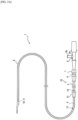
FIG. 1 is a plan view illustrating an image diagnosis catheter according to a first embodiment to which an external device is connected; -
FIG. 2A is a side view illustrating the image diagnosis catheter illustrated inFIG. 1 at a frontmost position before pull-back operation; -
FIG. 2B is a side view illustrating the image diagnosis catheter illustrated inFIG. 1 at a backmost position after pull-back operation; -
FIG. 3 is a cross-sectional view illustrating a distal end of the image diagnosis catheter illustrated inFIG. 1 ; -
FIG. 4 is a cross-sectional view illustrating a proximal end of the image diagnosis catheter illustrated inFIG. 1 ; -
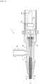
FIG. 5A is a cross-sectional view illustrating a pull-back mechanism of the image diagnosis catheter illustrated inFIG. 1 at the backmost position; -
FIG. 5B is a cross-sectional view illustrating the pull-back mechanism of the image diagnosis catheter illustrated inFIG. 1 at the frontmost position; -
FIG. 6 is a cross-sectional view illustrating a modification of the pull-back mechanism at the backmost position; -
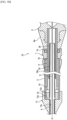
FIG. 7A is a cross-sectional view illustrating another modification of the pull-back mechanism at the backmost position; -
FIG. 7B is a cross-sectional view of the pull-back mechanism illustrated inFIG. 7A at the frontmost position; and -
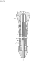
FIG. 8 is a cross-sectional view illustrating another modification of the pull-back mechanism at the backmost position. - Hereinafter, an embodiment of this disclosure will be described in detail with reference to the drawings.
- An
image diagnosis catheter 1 according to this embodiment illustrated inFIG. 1 is of a dual type employing both intravascular ultrasound (IVUS) and optical coherence tomography (OCT). The dual-typeimage diagnosis catheter 1 offers three modes, that is, a mode of acquiring a tomographic image by IVUS, a mode of acquiring a tomographic image by OCT, and a mode of acquiring a tomographic image by both IVUS and OCT, and these modes are switched from one to another. As illustrated inFIG. 1 , theimage diagnosis catheter 1 is connected to an external device 2 and driven. Theimage diagnosis catheter 1 and the external device 2 constitute an image diagnosis apparatus 3. - The
image diagnosis catheter 1 includes asheath 4 to be inserted into a body cavity such as a vascular channel (for example, coronary arteries or other blood vessels) of a living body, anouter tube 5 connected to a proximal end of thesheath 4, aninner tube 6 inserted into theouter tube 5 and movable forward and backward, a unit connector 7 that is connected to a proximal end of theouter tube 5 and holds theinner tube 6 while allowing theinner tube 6 to move forward and backward, and ahub 8 connected to a proximal end of theinner tube 6. Theimage diagnosis catheter 1 further includes animaging core 12 provided with adrive shaft 9, ahousing 10 fixed to a distal end of thedrive shaft 9, and a signal transmitter andreceiver 11 that is housed in thehousing 10 and transmits and receives a signal, that is, an ultrasound wave and/or light. Theimaging core 12 is inserted into thesheath 4, theouter tube 5, and theinner tube 6 and axially movable forward and backward with theinner tube 6 and relative to thesheath 4 and theouter tube 5. - In this specification, "distal end" signifies an end of the
image diagnosis catheter 1 to be inserted into a body cavity, "proximal end" signifies an end of theimage diagnosis catheter 1 to be held outside the body cavity, "axially (or axial direction)" signifies a direction along a central axis O of the drive shaft 9 (that is, a direction in which thedrive shaft 9 extends), "radially (or radial direction)" signifies a direction along a straight line perpendicular to the central axis O, and "circumferential direction" signifies a direction around the central axis O. - As illustrated in
FIG. 2A , thedrive shaft 9 extends to the inside of thehub 8 through thesheath 4, theouter tube 5, and theinner tube 6. Thehub 8, theinner tube 6, thedrive shaft 9, thehousing 10, and the signal transmitter andreceiver 11 are connected to each other and axially movable forward and backward all together relative to thesheath 4 and theouter tube 5. For this reason, for example, when thehub 8 is pushed toward the distal side, that is, when push-forward operation is performed, theinner tube 6 connected to thehub 8 is pushed into theouter tube 5 and the unit connector 7, whereby thedrive shaft 9, thehousing 10, and the signal transmitter andreceiver 11, that is, theimaging core 12 moves forward inside thesheath 4, that is, toward the distal side. For example, when thehub 8 is pulled toward the proximal side, that is, when pull-back operation is performed, theinner tube 6 is drawn out of theouter tube 5 and the unit connector 7 as indicated by arrow A1 inFIGS. 1 and2B , whereby theimaging core 12 moves toward the proximal side inside thesheath 4 as indicated by arrow A2. - As illustrated in
FIG. 2A , when theinner tube 6 is pushed furthest toward the distal side to a frontmost position, a distal end of theinner tube 6 comes close to arelay connector 13. At this time, the signal transmitter andreceiver 11 is located at a distal end of the sheath 4 (near a distal-end surface of a lumen of the sheath 4). Therelay connector 13 connects thesheath 4 with theouter tube 5. - As illustrated in
FIG. 2B , the distal end of theinner tube 6 is provided with a lockingportion 14 to prevent disengagement. The lockingportion 14 prevents theinner tube 6 from falling off theouter tube 5. The lockingportion 14 is configured to be hooked at a predetermined position on an inner wall of the unit connector 7 when thehub 8 is pulled toward the proximal side to a backmost position, that is, when theinner tube 6 is drawn furthest from theouter tube 5 and the unit connector 7. - As illustrated in
FIG. 3 , thedrive shaft 9 is an elongated hollow member, and the inside of thedrive shaft 9 is provided with an electric signal line (electric cable) 15 and an optical signal line (optical fiber) 16 which are connected to the signal transmitter andreceiver 11. - The
drive shaft 9 is formed of a coil shaft. Although not illustrated, the coil shaft is formed using, for example, coils with multiple layers having different winding directions. Each coil is made of, for example, metal such as stainless steel or nickel-titanium (Ni-Ti) alloy. - The signal transmitter and
receiver 11 includes an ultrasound transmitter andreceiver 11a that transmits and receives an ultrasound wave and an optical transmitter andreceiver 11b that transmits and receives light. The ultrasound transmitter andreceiver 11a includes a transducer that transmits an ultrasound wave into a body cavity based on a pulse signal and receives an ultrasound wave reflected from a biological tissue in the body cavity. The transducer is electrically connected to anelectrical connector 15a (seeFIG. 4 ) via theelectric signal line 15. The transducer is formed of, for example, a piezoelectric material such as ceramics or quartz. - The optical transmitter and
receiver 11b includes an optical element that transmits light into a body cavity and receives light reflected from a biological tissue in the body cavity. The optical element is optically connected to anoptical connector 16a (seeFIG. 4 ) via theoptical signal line 16. The optical element is formed using, for example, a lens such as ball lens. - The signal transmitter and
receiver 11 is housed in thehousing 10. A proximal end of thehousing 10 is fixed to the distal end of thedrive shaft 9. Thehousing 10 is formed of a cylindrical metallic tube and has a peripheral surface provided with anopening 10a so as not to hinder the progress of a signal transmitted and received by the signal transmitter andreceiver 11. Thehousing 10 is formed by, for example, laser processing. Note that thehousing 10 may be formed by shaving a metal lump, metallic powder injection molding (MIM), or the like. - A distal end of the
housing 10 is provided with adistal end member 17. Thedistal end member 17 has a substantially hemispherical outer shape so as not to cause friction against or not to hit an inner surface of thesheath 4. Note that thedistal end member 17 may be omitted. - The
sheath 4 has thelumen 4a into which thedrive shaft 9 is inserted while being movable forward and backward. To the distal end of thesheath 4, a tubular guidewire insertion member 18 that allows passage of a guide wire is attached while being shifted from an axial center of the lumen of thesheath 4. Thesheath 4 and the guidewire insertion member 18 are bonded by welding or the like. The guidewire insertion member 18 is provided with amarker 19 having X-ray contrast properties. Themarker 19 includes a pipe made of metal having high X-ray impermeability such as Pt or Au. - The distal end of the
sheath 4 is provided with acommunication hole 20 that allows communication between the inside and outside of thelumen 4a. Furthermore, a reinforcingmember 21 joined to the guidewire insertion member 18 is disposed at a distal end of thelumen 4a of thesheath 4. The reinforcingmember 21 has a through-hole that allows communication between thecommunication hole 20 and thelumen 4a disposed closer to the proximal side than the reinforcingmember 21. Note that the distal end of thesheath 4 is not necessarily provided with the reinforcingmember 21. - The
communication hole 20 is a priming solution discharge hole for discharging a priming solution. When theimage diagnosis catheter 1 is used, at the time of priming for filling thesheath 4 with the priming solution, the priming solution is released from thecommunication hole 20 to the outside so as to discharge a gas such as air from the inside of thesheath 4 together with the priming solution. - A distal end portion of the
sheath 4, or an area in which the signal transmitter andreceiver 11 moves in the axial direction of thesheath 4, is formed into a window having higher permeability than other portions. Thesheath 4, the guidewire insertion member 18, and the reinforcingmember 21 are formed of flexible materials. Examples of the materials include, but are not particularly limited to, various thermoplastic elastomers based on styrene, polyolefin, polyurethane, polyester, polyamide, polyimide, polybutadiene, trans-polyisoprene, fluoro-rubber, or chlorinated polyethylene. These examples may be used independently, or two or more of these examples (such as polymer alloy, polymer blend, and laminate) may be combined. - As illustrated in
FIG. 4 , thehub 8 includes ahub body 8a having a tubular shape coaxial with theinner tube 6 and detachably attached to the external device 2 in an integrated manner, aport 8b protruding from thehub body 8a toward the radially outer side and communicated with the inside of thehub body 8a, a connectingpipe 8c attached to an outer peripheral surface of thedrive shaft 9 in an integrated manner, abearing 8d rotatably supporting the connectingpipe 8c, a sealing member (first sealingmember 8e) that prevents the priming solution from leaking from a gap between the connectingpipe 8c and the bearing 8d toward the proximal side; and aconnector 8f provided with theelectrical connector 15a and theoptical connector 16a and detachably attached to afirst drive unit 2a of the external device 2 in an integrated manner. Theconnector 8f rotates the connectingpipe 8c and thedrive shaft 9 in an integrated manner. - The proximal end of the
inner tube 6 is connected to a distal end of thehub body 8a in an integrated manner. Thedrive shaft 9 is drawn out of theinner tube 6 inside thehub body 8a. - As illustrated in
FIG. 1 , aninjection device 22 that injects the priming solution during the priming is connected to theport 8b. Theinjection device 22 includes aconnector 22a connected to theport 8b and a syringe (not illustrated) connected to theconnector 22a via atube 22b. The priming is typically performed at the backmost position (seeFIGS. 1 and5A ). - The external device 2 includes the
first drive unit 2a for driving thedrive shaft 9 to rotate and asecond drive unit 2b for axially moving the drive shaft 9 (that is, for push-forward operation and pull-back operation). Thefirst drive unit 2a includes, for example, an electrical motor. Thesecond drive unit 2b includes, for example, an electrical motor and a direct motion conversion mechanism. The direct motion conversion mechanism converts rotational motions into linear motions and includes, for example, a ball screw and a rack-and-pinion mechanism. - Operations of the
first drive unit 2a and thesecond drive unit 2b are controlled by acontrol device 2c electrically connected to thefirst drive unit 2a and thesecond drive unit 2b. Thecontrol device 2c includes a central processing unit (CPU) and a memory. Thecontrol device 2c is electrically connected to adisplay 2d. - A signal received by the ultrasound transmitter and
receiver 11a is transmitted to thecontrol device 2c via theelectrical connector 15a, subjected to predetermined processing, and shown on thedisplay 2d as an image. A signal received by the optical transmitter andreceiver 11b is transmitted to thecontrol device 2c via theoptical connector 16a, subjected to predetermined processing, and shown on thedisplay 2d as an image. - At diagnosis, while the
sheath 4 is inserted into a body cavity and theimaging core 12 is driven by thefirst drive unit 2a of the external device 2 to rotate at a constant rotational speed of about 1000 to 10000 rpm, theimaging core 12 moves backward at a constant speed inside thelumen 4a of thesheath 4 due to pull-back operation by thesecond drive unit 2b of the external device 2. At this time, thecontrol device 2c of the external device 2 causes the signal transmitter andreceiver 11 to transmit and receive a signal. A condition of a tissue around the body cavity is shown on thedisplay 2d as an image based on the signal received by scanning by rotating and moving backward. - In this manner, the
image diagnosis catheter 1 has a pull-back mechanism 23 on a side closer to a user's hand for changing a relative position between thesheath 4 and thedrive shaft 9 in order to continuously monitor a cross section of a body cavity. As described inFIGS. 5A and5B , the pull-back mechanism 23 includes theouter tube 5,' theinner tube 6 disposed on the radially inner side of theouter tube 5 and radially outer side of thedrive shaft 9 and axially movable with thedrive shaft 9 and relative to theouter tube 5, afirst support tube 24 disposed on the radially inner side of theinner tube 6 and radially outer side of thedrive shaft 9, aspacer 25 connecting theouter tube 5 and thefirst support tube 24 in an integrated manner, therelay connector 13, and the unit connector 7. As described above, therelay connector 13 is connected to thesheath 4 in an integrated manner, and theinner tube 6 is connected to thehub 8 in an integrated manner. The unit connector 7 is provided with a sealing member (second sealingmember 7a) that prevents the priming solution from leaking from a gap between the unit connector 7 and theinner tube 6 toward the proximal side. - The distal end of the
inner tube 6 is provided with the lockingportion 14. The lockingportion 14 includes an enlarged diameter portion where an outer peripheral surface of theinner tube 6 is enlarged in diameter. A back-end surface of the lockingportion 14 protrudes from the outer peripheral surface of theinner tube 6 toward the radially outer side and has an annular shape centering on the central axis O. The unit connector 7 has astopper surface 7b that abuts on the back-end surface of the lockingportion 14 to restrict further backward movement of theinner tube 6. Theinner tube 6 has a diameter sufficient to offer sufficient strength to the lockingportion 14 as a stopper. - In this embodiment, the pull-
back mechanism 23 includes asecond support tube 26 disposed on the radially inner side of theinner tube 6 and radially outer side of thedrive shaft 9 and axially movable with thedrive shaft 9 and theinner tube 6 and relative to theouter tube 5 and thefirst support tube 24. In this embodiment, thesecond support tube 26 is disposed on the radially outer side of thefirst support tube 24. Thesecond support tube 26 is connected to thehub 8 and/or theinner tube 6 in an integrated manner. - The structure for connecting the
second support tube 26 and thehub 8 in an integrated manner is not particularly limited. For example, a proximal end of thesecond support tube 26 may be bonded to thehub 8 directly or via another member with an adhesive or the like. The structure for connecting thesecond support tube 26 to theinner tube 6 in an integrated manner is not particularly limited. For example, the proximal end or distal end of thesecond support tube 26 or a portion therebetween may be bonded to theinner tube 6 directly or via another member with an adhesive or the like. For example, aprotrusion 26a (see a dashed-two dotted line inFIG. 5B ) protruding toward the radially outer side may be disposed in a part of an outer wall of thesecond support tube 26, and theprotrusion 26a and an inner wall of theinner tube 6 may be bonded to each other. Theprotrusion 26a may be disposed in a part in the circumferential direction or over the entire circumference. According to the structure in which thesecond support tube 26 and theinner tube 6 are bonded to each other, it is possible to easily ensure the coaxiality of thesecond support tube 26. With such a structure, when thesecond support tube 26 moves forward or backward, it is possible to reduce the possibility that thesecond support tube 26 comes into contact with thefirst support tube 24 and is hindered from smoothly moving forward and backward. A flanged member may be connected to the proximal end of thesecond support tube 26 in an integrated manner, and the flanged member may be sandwiched and fixed between the proximal end of theinner tube 6 and thehub 8. An outer peripheral surface of thesecond support tube 26 may be connected to an inner peripheral surface of theinner tube 6 via one or more axially extending ribs. In this case, thesecond support tube 26 and theinner tube 6 may be formed in an integrated manner by extrusion molding or the like. - In the pull-
back mechanism 23, theouter tube 5, thefirst support tube 24, theinner tube 6, thedrive shaft 9, and thesecond support tube 26 are coaxial and share the central axis O. - The
relay connector 13 has a cylindrical shape, including a proximal-side innerperipheral surface 13a having a columnar shape and a distal-side innerperipheral surface 13c having a columnar shape that is connected to a distal end of the proximal-side innerperipheral surface 13a via an annular steppedportion 13b. An outer peripheral surface of the proximal end of thesheath 4 is joined to the distal-side innerperipheral surface 13c by welding or the like. An outer peripheral surface of a distal end of theouter tube 5 is joined to the proximal-side innerperipheral surface 13a by welding or the like. - The
spacer 25 has a tubular shape, an outer peripheral surface of thespacer 25 is in contact with an inner peripheral surface of the distal end of theouter tube 5, and an inner peripheral surface of thespacer 25 is in contact with an outer peripheral surface of a distal end of thefirst support tube 24. The outer peripheral surface of thespacer 25 is joined to the inner peripheral surface of the distal end of theouter tube 5 by welding or the like, and the inner peripheral surface of thespacer 25 is joined to the outer peripheral surface of the distal end of thefirst support tube 24 by welding or the like. Furthermore, thespacer 25 is made of, for example, synthetic resin or metal. - The
first support tube 24 is formed of, for example, a coil or a tube with a single layer or multiple layers. Thefirst support tube 24 is made of, for example, synthetic resin or metal. Using the coiledfirst support tube 24 enables the priming solution to pass radially through thefirst support tube 24, which promotes priming inside theouter tube 5. Instead of the coil shape, thefirst support tube 24 may be formed into a tubular shape entirely or partially provided with meshed cutouts or the like. Thefirst support tube 24 may be formed into a tubular shape without cutouts. In this case, in order to promote priming the inside theouter tube 5, it is preferable that thespacer 25 is provided with a channel that allows passage of the priming solution. - The
second support tube 26 is formed of, for example, a coil or a tube with a single layer or multiple layers. Thesecond support tube 26 is made of, for example, synthetic resin or metal. Using the coiledsecond support tube 26 enables the priming solution to pass radially through thesecond support tube 26, which promotes priming inside theinner tube 6. Instead of the coil shape, thesecond support tube 26 may be formed into a tubular shape entirely or partially provided with meshed cutouts or the like. Thesecond support tube 26 may be formed into a tubular shape without cutouts. In this case, in order to promote priming inside theinner tube 6, it is preferable that the proximal end of thesecond support tube 26 is connected to thehub 8 or theinner tube 6 via a member forming a channel that allows passage of the priming solution. - When the
inner tube 6, thesecond support tube 26, and thedrive shaft 9 move forward relative to theouter tube 5 and thefirst support tube 24 by push-forward operation (for example, from the backmost position illustrated inFIG. 5A to the frontmost position illustrated inFIG. 5B ), thedrive shaft 9 is prevented from being buckled inside the outer tube 5 (for example, as indicated by a dashed-two dotted line inFIG. 5A ) by thefirst support tube 24 supporting thedrive shaft 9 from the radially outer side, and simultaneously, thedrive shaft 9 is prevented from being buckled inside the inner tube 6 (for example, as indicated by a dashed-two dotted line inFIG. 5A ) by thesecond support tube 26 supporting thedrive shaft 9 from the radially outer side. Accordingly, it is possible to prevent thedrive shaft 9 from being driven to rotate while being buckled inside the pull-back mechanism 23, whereby thedrive shaft 9 is prevented from being broken and wrenched off. - In order to enhance the effect of preventing the buckling of the
drive shaft 9, it is preferable that thesecond support tube 26 overlaps thefirst support tube 24 in the radial direction at the frontmost position where theinner tube 6 is pushed furthest into theouter tube 5, and it is more preferable that thesecond support tube 26 overlaps thefirst support tube 24 in the radial direction even at the backmost position where theinner tube 6 is drawn furthest from theouter tube 5 as in this embodiment. However, the length of thesecond support tube 26 is set within a range that does not hinder the telescopic action of the pull-back mechanism 23. For example, as in a modification illustrated inFIG. 6 , thesecond support tube 26 does not necessarily overlap thefirst support tube 24 in the radial direction at the backmost position and may overlap thefirst support tube 24 at the frontmost position. Alternatively, although not illustrated, thesecond support tube 26 does not necessarily overlap thefirst support tube 24 in the radial direction even at the frontmost position. - In this embodiment, since the
second support tube 26 is disposed on the radially outer side of thefirst support tube 24 as described above, the second support tube has an inside diameter larger than that of the first support tube , whereby the buckling of thedrive shaft 9 is prevented in a stepwise manner from the proximal side toward the distal side. Preventing the buckling of thedrive shaft 9 in a stepwise manner prevents the breakage more efficiently. - However, as in another modification illustrated in
FIGS. 7A and7B , thesecond support tube 26 may be disposed on the radially inner side of thefirst support tube 24. In other words, in this modification, thesecond support tube 26, thefirst support tube 24, theinner tube 6, and theouter tube 5 are disposed on the radially outer side of thedrive shaft 9 in this order. In this modification, the proximal end of thesecond support tube 26 is connected to thehub 8 and/or theinner tube 6 in an integrated manner and directly or via another member with an adhesive or the like. - Depending on materials of the
first support tube 24 or thesecond support tube 26, there is a possibility that thedrive shaft 9 may be buckled and broken together with thefirst support tube 24 or thesecond support tube 26. The buckling is most likely to occur inside theouter tube 5 having a largest space that allows the buckling. In a case where thesecond support tube 26 is disposed on the radially inner side of thefirst support tube 24, thefirst support tube 24 is made to have an increased outside diameter while thesecond support tube 26 is kept to have a small inside diameter (that is, thefirst support tube 24 is made to have an increased thickness), thereby enhancing the rigidity inside theouter tube 5. Accordingly, it is possible to prevent thedrive shaft 9 from being buckled and broken together with thefirst support tube 24 inside theouter tube 5. - As in another modification illustrated in
FIG. 8 , thefirst support tube 24 does not necessarily overlap theinner tube 6 in the radial direction at the backmost position where theinner tube 6 is drawn furthest from theouter tube 5. In other words, in this modification, the proximal end of thefirst support tube 24 is positioned closer to the distal side than the distal end of theinner tube 6 at the backmost position. According to this configuration, as compared with the configuration illustrated inFIG. 7A in which thefirst support tube 24 overlaps theinner tube 6 in the radial direction at the backmost position, it is possible to easily ensure a large cross-sectional area at a proximal end of a priming channel formed on the radially outer side of thefirst support tube 24 when the priming is performed at the backmost position. Accordingly, as indicated by outlined arrows inFIG. 8 , the priming solution is easily introduced from the proximal side into a cavity portion surrounded by the inner peripheral surface of theouter tube 5 and the outer peripheral surface of thefirst support tube 24, or the largest cavity portion on the side closer to a user's hand, and priming is promoted inside theouter tube 5. - In this modification, the
second support tube 26 may be on the radially outer side of thefirst support tube 24. However, as illustrated inFIG. 8 , the configuration in which thesecond support tube 26 is on the radially inner side of thefirst support tube 24 is preferable because it is easier to obtain the effect of promoting priming. - In this modification, the
first support tube 24 does not necessarily overlap thesecond support tube 26 in the radial direction at the backmost position. However, as illustrated inFIG. 8 , it is preferable that thefirst support tube 24 overlaps thesecond support tube 26 in the radial direction at the backmost position because it is possible to promote priming inside thefirst support tube 24. - As described above, according to this embodiment and the modifications thereof, not only the
first support tube 24 prevents the buckling of thedrive shaft 9 inside theouter tube 5 during push-forward operation but also thesecond support tube 26 prevents the buckling of thedrive shaft 9 inside theinner tube 6 during push-forward operation. Accordingly, it is possible to prevent thedrive shaft 9 from being driven to rotate while being buckled inside the pull-back mechanism 23, whereby thedrive shaft 9 is prevented from being broken and wrenched off. - This disclosure is not limited to the above embodiments and can be modified in various ways without departing from the gist of the present invention.
- Therefore, the
image diagnosis catheter 1 according to the embodiment can be changed in various ways as described below. - The
image diagnosis catheter 1 according to the embodiment can be changed in various ways as long as theimage diagnosis catheter 1 includes: theouter tube 5; thefirst support tube 24 disposed on the radially inner side of theouter tube 5; thedrive shaft 9 disposed on the radially inner side of thefirst support tube 24; theinner tube 6 disposed on the radially inner side of theouter tube 5 and radially outer side of thefirst support tube 24; and thesecond support tube 26 disposed on the radially inner side of theinner tube 6 and radially outer side of thedrive shaft 9, being axially movable with thedrive shaft 9 and theinner tube 6 and relative to theouter tube 5 and thefirst support tube 24. - For example, without the
spacer 25, the distal end of thefirst support tube 24 may be directly connected to therelay connector 13 or theouter tube 5 in an integrated manner using an adhesive or the like. - The pull-
back mechanism 23 is not limited to the configuration in which theouter tube 5 is connected to therelay connector 13 in an integrated manner and theinner tube 6 is connected to thehub 8 in an integrated manner and may have a configuration in which theouter tube 5 is connected to thehub 8 in an integrated manner and theinner tube 6 is connected to therelay connector 13 in an integrated manner. - The
image diagnosis catheter 1 is not limited to a dual-type using both IVUS and OCT and may be of a type using only IVUS or OCT. - In the
image diagnosis catheter 1 according to the embodiment, it is preferable that thesecond support tube 26 overlaps thefirst support tube 24 in the radial direction at the frontmost position where theinner tube 6 is pushed furthest into theouter tube 5. - In the
image diagnosis catheter 1 according to the embodiment, it is preferable that thesecond support tube 26 overlaps thefirst support tube 24 in the radial direction even at the backmost position where theinner tube 6 is drawn furthest from theouter tube 5. - In the
image diagnosis catheter 1 according to the embodiment, it is preferable that thesecond support tube 26 is disposed on the radially outer side of thefirst support tube 24. - In this case, it is preferable that the
image diagnosis catheter 1 includes thehub 8 connected to the proximal end of theinner tube 6, and thesecond support tube 26 is connected to thehub 8 or theinner tube 6 in an integrated manner. - In the
image diagnosis catheter 1 according to the embodiment, it is also preferable that thesecond support tube 26 is disposed on the radially inner side of thefirst support tube 24. - In this case, it is preferable that the
image diagnosis catheter 1 includes thehub 8 connected to the proximal end of theinner tube 6, and thesecond support tube 26 is connected to thehub 8 in an integrated manner. - In the
image diagnosis catheter 1 according to the embodiment, it is preferable that thesecond support tube 26 has a coil shape. - In the
image diagnosis catheter 1 according to the embodiment, it is preferable that thefirst support tube 24 does not overlap theinner tube 6 in the radial direction at the backmost position where theinner tube 6 is drawn furthest from theouter tube 5. -
- 1
- Image diagnosis catheter
- 2
- External device
- 2a
- First drive unit
- 2b
- Second drive unit
- 2c
- Control device
- 2d
- Display
- 3
- Image diagnosis apparatus
- 4
- Sheath
- 4a
- Lumen
- 5
- Outer tube
- 6
- Inner tube
- 7
- Unit connector
- 7a
- Second sealing member
- 7b
- Stopper surface
- 8
- Hub
- 8a
- Hub body
- 8b
- Port
- 8c
- Connecting pipe
- 8d
- Bearing
- 8e
- First sealing member
- 8f
- Connector
- 9
- Drive shaft
- 10
- Housing
- 10a
- Opening
- 11
- Signal transmitter and receiver
- 11a
- Ultrasound transmitter and receiver
- 11b
- Optical transmitter and receiver
- 12
- Imaging core
- 13
- Relay connector
- 13a
- Proximal-side inner peripheral surface
- 13b
- Annular stepped portion
- 13c
- Distal-side inner peripheral surface
- 14
- Locking portion
- 15
- Electric signal line
- 15a
- Electrical connector
- 16
- Optical signal line
- 16a
- Optical connector
- 17
- Distal end member
- 18
- Guide wire insertion member
- 19
- Marker
- 20
- Communication hole
- 21
- Reinforcing member
- 22
- Injection device
- 22a
- Connector
- 22b
- Tube
- 23
- Pull-back mechanism
- 24
- First support tube
- 25
- Spacer
- 26
- Second support tube
- 26a
- Protrusion
- O
- Central axis
Claims (9)
- An image diagnosis catheter comprising: an outer tube; a first support tube disposed on the radially inner side of the outer tube; a drive shaft disposed on the radially inner side of the first support tube; an inner tube disposed on the radially inner side of the outer tube and radially outer side of the first support tube; and a second support tube disposed on the radially inner side of the inner tube and radially outer side of the drive shaft, being axially movable with the drive shaft and the inner tube and relative to the outer tube and the first support tube.
- The image diagnosis catheter according to claim 1, wherein the second support tube overlaps the first support tube in a radial direction at a frontmost position where the inner tube is pushed furthest into the outer tube.
- The image diagnosis catheter according to claim 2, wherein the second support tube overlaps the first support tube in the radial direction even at a backmost position where the inner tube is drawn furthest from the outer tube.
- The image diagnosis catheter according to any one of claims 1 to 3, wherein the second support tube is disposed on the radially outer side of the first support tube.
- The image diagnosis catheter according to claim 4, whereinthe image diagnosis catheter comprises a hub connected to a proximal end of the inner tube, andthe second support tube is connected to the hub or the inner tube in an integrated manner.
- The image diagnosis catheter according to any one of claims 1 to 3, wherein the second support tube is disposed on the radially inner side of the first support tube.
- The image diagnosis catheter according to claim 6, whereinthe image diagnosis catheter comprises a hub connected to a proximal end of the inner tube, andthe second support tube is connected to the hub in an integrated manner.
- The image diagnosis catheter according to any one of claims 1 to 7, wherein the second support tube has a coil shape.
- The image diagnosis catheter according to any one of claims 1 to 8, wherein the first support tube does not overlap the inner tube in the radial direction at a backmost position where the inner tube is drawn furthest from the outer tube.
Applications Claiming Priority (2)
| Application Number | Priority Date | Filing Date | Title |
|---|---|---|---|
| JP2021126235 | 2021-07-30 | ||
| PCT/JP2022/029205 WO2023008539A1 (en) | 2021-07-30 | 2022-07-28 | Catheter for diagnostic imaging |
Publications (2)
| Publication Number | Publication Date |
|---|---|
| EP4364672A1 true EP4364672A1 (en) | 2024-05-08 |
| EP4364672A4 EP4364672A4 (en) | 2024-10-30 |
Family
ID=85086865
Family Applications (1)
| Application Number | Title | Priority Date | Filing Date |
|---|---|---|---|
| EP22849600.6A Pending EP4364672A4 (en) | 2021-07-30 | 2022-07-28 | CATHETER FOR DIAGNOSTIC IMAGING |
Country Status (5)
| Country | Link |
|---|---|
| US (1) | US20240156347A1 (en) |
| EP (1) | EP4364672A4 (en) |
| JP (1) | JPWO2023008539A1 (en) |
| CN (1) | CN117715594A (en) |
| WO (1) | WO2023008539A1 (en) |
Families Citing this family (1)
| Publication number | Priority date | Publication date | Assignee | Title |
|---|---|---|---|---|
| WO2025126755A1 (en) * | 2023-12-11 | 2025-06-19 | テルモ株式会社 | Catheter for diagnostic imaging |
Family Cites Families (6)
| Publication number | Priority date | Publication date | Assignee | Title |
|---|---|---|---|---|
| US4672188A (en) | 1985-08-05 | 1987-06-09 | International Business Machines Corporation | Focus detector for optical apparatus |
| JP4672188B2 (en) | 2001-06-08 | 2011-04-20 | テルモ株式会社 | Ultrasound catheter |
| JP5551397B2 (en) * | 2009-09-30 | 2014-07-16 | テルモ株式会社 | Diagnostic imaging catheter |
| JP5576665B2 (en) * | 2010-01-27 | 2014-08-20 | テルモ株式会社 | In-vivo diagnostic apparatus and control method thereof |
| WO2013133356A1 (en) * | 2012-03-09 | 2013-09-12 | テルモ株式会社 | Catheter |
| JP6247160B2 (en) * | 2014-06-12 | 2017-12-13 | テルモ株式会社 | Medical device |
-
2022
- 2022-07-28 EP EP22849600.6A patent/EP4364672A4/en active Pending
- 2022-07-28 WO PCT/JP2022/029205 patent/WO2023008539A1/en not_active Ceased
- 2022-07-28 CN CN202280052995.9A patent/CN117715594A/en active Pending
- 2022-07-28 JP JP2023538629A patent/JPWO2023008539A1/ja active Pending
-
2024
- 2024-01-24 US US18/421,217 patent/US20240156347A1/en active Pending
Also Published As
| Publication number | Publication date |
|---|---|
| EP4364672A4 (en) | 2024-10-30 |
| CN117715594A (en) | 2024-03-15 |
| WO2023008539A1 (en) | 2023-02-02 |
| US20240156347A1 (en) | 2024-05-16 |
| JPWO2023008539A1 (en) | 2023-02-02 |
Similar Documents
| Publication | Publication Date | Title |
|---|---|---|
| JP5188242B2 (en) | In vivo insertion probe | |
| JP7173968B2 (en) | diagnostic imaging catheter | |
| WO2021065312A1 (en) | Medical instrument set and tubular member | |
| JP7179943B2 (en) | diagnostic imaging catheter | |
| JP7618513B2 (en) | Diagnostic Imaging Catheters | |
| US20240156347A1 (en) | Image diagnosis catheter | |
| JP7853278B2 (en) | Diagnostic imaging catheter | |
| US10905395B2 (en) | Diagnostic imaging catheter | |
| JP5171354B2 (en) | In vivo diagnostic imaging probe | |
| JP2015066036A (en) | Imaging diagnosis catheter | |
| JP7776487B2 (en) | Diagnostic imaging catheters | |
| US20180214670A1 (en) | Diagnostic imaging catheter | |
| JP2012205661A (en) | Catheter assembly | |
| JP7672421B2 (en) | Drive shaft and imaging catheter | |
| EP3545825B1 (en) | Image diagnosis catheter | |
| JP7825482B2 (en) | Diagnostic imaging catheters | |
| JP6823043B2 (en) | Medical device | |
| WO2022071157A1 (en) | Driving shaft and catheter for image diagnosis | |
| HK40103918A (en) | Catheter for diagnostic imaging | |
| JP6779799B2 (en) | Medical device | |
| JP2025145702A (en) | Diagnostic imaging catheters | |
| JP2023038812A (en) | diagnostic imaging catheter | |
| HK40104095A (en) | Image diagnosis catheter | |
| US20180199912A1 (en) | Catheter | |
| JP7245704B2 (en) | Catheter and method of disassembling the catheter |
Legal Events
| Date | Code | Title | Description |
|---|---|---|---|
| STAA | Information on the status of an ep patent application or granted ep patent |
Free format text: STATUS: THE INTERNATIONAL PUBLICATION HAS BEEN MADE |
|
| PUAI | Public reference made under article 153(3) epc to a published international application that has entered the european phase |
Free format text: ORIGINAL CODE: 0009012 |
|
| STAA | Information on the status of an ep patent application or granted ep patent |
Free format text: STATUS: REQUEST FOR EXAMINATION WAS MADE |
|
| 17P | Request for examination filed |
Effective date: 20240201 |
|
| AK | Designated contracting states |
Kind code of ref document: A1 Designated state(s): AL AT BE BG CH CY CZ DE DK EE ES FI FR GB GR HR HU IE IS IT LI LT LU LV MC MK MT NL NO PL PT RO RS SE SI SK SM TR |
|
| A4 | Supplementary search report drawn up and despatched |
Effective date: 20241002 |
|
| RIC1 | Information provided on ipc code assigned before grant |
Ipc: A61B 5/00 20060101ALI20240926BHEP Ipc: A61B 1/00 20060101ALI20240926BHEP Ipc: A61B 8/12 20060101AFI20240926BHEP |
|
| DAV | Request for validation of the european patent (deleted) | ||
| DAX | Request for extension of the european patent (deleted) |