EP4364564B1 - Nagetierfalle - Google Patents
Nagetierfalle Download PDFInfo
- Publication number
- EP4364564B1 EP4364564B1 EP24166016.6A EP24166016A EP4364564B1 EP 4364564 B1 EP4364564 B1 EP 4364564B1 EP 24166016 A EP24166016 A EP 24166016A EP 4364564 B1 EP4364564 B1 EP 4364564B1
- Authority
- EP
- European Patent Office
- Prior art keywords
- trap
- rodent
- bar
- spring
- traps
- Prior art date
- Legal status (The legal status is an assumption and is not a legal conclusion. Google has not performed a legal analysis and makes no representation as to the accuracy of the status listed.)
- Active
Links
Images







Classifications
-
- A—HUMAN NECESSITIES
- A01—AGRICULTURE; FORESTRY; ANIMAL HUSBANDRY; HUNTING; TRAPPING; FISHING
- A01M—CATCHING, TRAPPING OR SCARING OF ANIMALS; APPARATUS FOR THE DESTRUCTION OF NOXIOUS ANIMALS OR NOXIOUS PLANTS
- A01M23/00—Traps for animals
- A01M23/24—Spring traps, e.g. jaw or like spring traps
- A01M23/30—Break-back traps, i.e. mouse-trap type
-
- A—HUMAN NECESSITIES
- A01—AGRICULTURE; FORESTRY; ANIMAL HUSBANDRY; HUNTING; TRAPPING; FISHING
- A01M—CATCHING, TRAPPING OR SCARING OF ANIMALS; APPARATUS FOR THE DESTRUCTION OF NOXIOUS ANIMALS OR NOXIOUS PLANTS
- A01M23/00—Traps for animals
- A01M23/24—Spring traps, e.g. jaw or like spring traps
-
- A—HUMAN NECESSITIES
- A01—AGRICULTURE; FORESTRY; ANIMAL HUSBANDRY; HUNTING; TRAPPING; FISHING
- A01M—CATCHING, TRAPPING OR SCARING OF ANIMALS; APPARATUS FOR THE DESTRUCTION OF NOXIOUS ANIMALS OR NOXIOUS PLANTS
- A01M31/00—Hunting appliances
- A01M31/002—Detecting animals in a given area
Definitions
- the present invention relates to a trap for small animals, e.g. rats and mices, such as a spring-loaded strike trap and a notifying/monitoring network of such spring-loaded strike traps operatively connected.
- a trap for small animals e.g. rats and mices
- a spring-loaded strike trap and a notifying/monitoring network of such spring-loaded strike traps operatively connected.
- rat traps there are many examples of different kind of rat traps having different structures and functionality, such as spring-loaded strike or snap traps.
- rat trap unit is disclosed in US 6,807,767 B1 .
- This rat trap is spring biased and has a plurality of light sources acting together to detect the position of a small animal to be trapped.
- One object of the invention is to provide a spring-loaded strike trap, which solves or at least reduces one or more of above problems.
- Another object is to provide a spring-loaded strike trap with a more versatile use/functionality than the basic pest killing by enabling monitoring and notifying the presence of excess water and/or sewage or the like liquid/fluid, e.g. during flooding and/or water/sewage leaks or the like when in use.
- a spring-loaded strike trap and/or one or more such spring-loaded strike traps being configured for operative connection and monitoring presence of excess water and/or sewage or the like liquid/fluid due to flooding and/or leaks, when in use in a net work being configured for communicating/notifying the presence of the excess liquid via wires and/or wirelessly, as claimed in the associated independent claims, preferred variants thereof being defined in associated dependent claims.
- a spring-loaded strike rat trap comprising at least one spring, a housing, at least one striker bar, at least one arming bar, at least one trigger plate, and at least one trigger, the spring being configured for biasing the bars to move from a first position, where the arming bar and the trigger plate is releasably held by the trigger and in contact with a ready indicator to indicate that the spring-loaded strike rat trap is charged, into at least one other position where the movement of the bars is stopped, after the spring-loaded strike rat trap is triggered releasing the bars, wherein the striker bar, when the spring-loaded strike rat trap is triggered releasing the striker bar, is either biased by the spring into contact with a firing indicator in a final and/or end position, if a rat or mouse is not hit, or biased into contact with a rat or mouse of a first and/or certain and/or predetermined size hitting and killing it in an intermediary position not in contact with any of the indicators, where
- the firing indicator and/or the ready indicator is made of a flexible material and/or has a shape making it flexible for broader application and/or larger tolerances and/or are less sensitive for deformations and/or provide smoother movement/engagement.
- the firing indicator and/or the ready indicator is a conductor/made of a conductive material for easy and quick signalling.
- the striking bar, the arming bar and the trigger plate are configured for rotating/pivoting around the same axis for more distinct movement.
- the spring is configured for biasing the striking bar and the arming bar to rotate/pivot around the same axis, which axis the trigger plate is configured for pivoting around when triggered for securing repeatability of movement.
- the striking bar and the arming bar both are made of conductive material and are configured for being in conductive connection with the same rotary/pivot axis for secure signals.
- the spring-loaded strike trap according to any of above and/or any or one or more of below aspects comprises an energiser configured for being in conductive connection with the same rotary/pivot axis as the striking bar and the arming bar for enhanced and more secure signalling with less noise and eliminated or at least very reduced risk of interrupted signals etc.
- the spring, the striker bar, the arming bar, the trigger plate and the trigger are configured for being arranged on an upper side of a bottom plate for forming a detachable inner inset configured for being a separate/autonomous inner part or module of the rat trap housing when assembled therein enabling easy replacement of the inner inset in case of a damaged one or update to a new version.
- the bottom plate of the detachable inner inset has the upper side and a lower side and the trigger plate is configured for being movably and/or pivotally attached to the upper bottom plate side via a rotary/pivot axis extending substantially in parallel or in parallel with the extension plane of the bottom plate or its bottom plate side for easier access and replacement from above.
- the bottom plate of the detachable inner inset has a plate shape defined by its upper side and lower side and two long sides and two short sides, the upper side and lower side are configured for forming substantially parallel and opposite planes (or parallel and opposite planes) extending substantially perpendicular or perpendicular to the long and short sides, which long and short sides are configured for forming pairwise substantially parallel and opposite sides (or parallel and opposite sides) relative each other, and the ready indicator comprises a first end configured for being arranged at one of the short or long sides of the bottom plate for conductive connection with the arming bar when in its first position when the detachable inner inset is assembled as a removable inner part or module into the rat trap as charged to provide easier assembly and disassembly and access to the detachable inner inset.
- the ready indicator comprises a second end configured for being arranged at one of the other short or long sides of the bottom plate in conductive connection with the arming bar when the detachable inner inset is assembled as a removable inner part or inner module into the rat trap as charged for enhanced signalling.
- the ready indicator and/or the firing indicator is/are configured for being arranged as a part of the detachable inner inset to enable a more compact and easily replaceable inner inset.
- the rat trap housing comprises an detachable outer upper casing or covering and an detachable outer bottom casing, which are configured for mating by being removably docketed together when the rat trap is assembled and configured for disconnection when the rat trap is disassembled providing an easier access of/to and enhanced detachability/assembly of the rat trap including its modules.
- the spring-loaded strike trap according to any of above and/or any or one or more of below aspects further comprises an detachable inner insert, when assembled, which is configured for removably receiving the detachable inner inset when the rat trap is assembled, the detachable inner insert being configured for comprising a power source and/or a control unit that provide an easy access to detachable rat trap modules and/or autonomous functionality and/or easy upgrading of each insert, such as replacing a "old" control unit to a newer one and also enables easy replacement of a broken one instead of having to replace a whole rat trap.
- an detachable inner insert is configured for removable connection/mating/docketing with the detachable outer bottom casing when the rat trap is assembled for easy and quick disassembly/assembly.
- an detachable inner insert or one or more outer coverings is configured for removable and/or fixedly mating/docketing with the detachable outer bottom casing when the rodent trap is assembled. If the outer covering is removably attached to the detachable outer bottom casing easy access to desired inner parts, e.g.
- the electronics and/or striker unit of the trap is enabled. If the outer covering is fixedly attached to the detachable outer bottom casing, the desired inner parts then being covered, e.g. the electronics and/or striker unit of the trap is more securely and robust protected, also against moist or the like that may negatively affect the functionality/electronics of the trap.
- the ready indicator and/or the firing indicator is configured for being arranged as a part of the detachable inner insert for easy access as separated from the inner inset.
- the ready indicator is configured for being arranged as a part of the detachable inner insert or the inner inset.
- the firing indicator is configured for being arranged as a part of the detachable inner insert or the inner inset.
- the spring-loaded strike trap according to any of above and/or any or one or more of below aspects further comprises an outer covering, when assembled, which is configured for at least removably or fixedly cover the detachable inner inset when the rodent trap is assembled, and/or a power source and/or an internal trap controller and/or a radio transmitter or the like.
- the spring-loaded strike trap according to any of above and/or any or one or more of below aspects comprises a housing made up of at least three parts, i.e. one or more outer coverings and a detachable bottom casing in which the inner inset for killing/catching rodents in turn is exchangeably assembled.
- the ready indicator and the firing indicator are elongated and configured for extending from their first ends at a position arranged on/at or above a first level defined as extending along the plane of the upper bottom plate side, towards the lower plate side and along this lower plate side at a second level defined as extending along the lower plate side towards and ending at their second ends for providing a more compact and space efficient design while securing good contact.
- the energiser is elongated and configured for extending from a first end at a position arranged on/at or above the first level of the upper bottom plate side, towards the lower plate side and along this lower plate side at the second level of the lower plate side towards and ending at a second end for providing a more compact and space efficient design while securing good contact and an easy access of the ends of the ready indicator, firing indicator and energiser both at assembly but also at disassembly.
- the energiser is configured for being arranged at the pivot axis in conductive connection with the arming bar when the trap is charged and in conductive connection with a power source and/or a control unit when the detachable inner inset is assembled as a removable inner part or inner module into the trap and configured for being in conductive connection with the striker bar when the trap is triggered and the striker bar has been released and come into conductive contact with the firing indicator and configured for being in conductive connection with the ready indicator and the firing indicator when water or the like conductive fluid has reached the second level to enhance and secure the signalling path and the reliability of the signalling.
- the spring-loaded strike trap comprises a movement and/or presence sensor for detecting an event in the rodent trap for pest control and for emitting a sensor signal in response to the event for direct communication with other rodent traps and/or directly with a data base and/or directly to or via a central/internal control unit to one or more other rodent traps and/or data bases, which movement and/or presence sensor in another aspect is a so-called passive infrared, PIR, sensor.
- PIR passive infrared
- At least one of the objects are achieved by a system or network of at least two spring-loaded strike traps according to any preceding and/or any or one or more of below aspects, wherein these at least two rodent traps are operatively connected to cooperate for eliminating or at least reducing or at least minimising a population of rats and/or mouses, wherein these at least two traps are configured to form a MESH network in which at least one and/or each and/or all rat traps continuously monitor presence of water or the like conductive fluid and that one or more of the rat traps is configured for registering if existing water or the like conductive fluid are at/over a certain/predetermined level by use of indicators that are conductively connected forming a closed circuit when the water or the like conductive fluid has reached the certain/predetermined level.
- no additional or external or separate sensor/-s or detector/-s for monitoring leakage of water or the like conductive fluid are needed in for example a house and/or skyscraper.
- one or more of the rat traps configured for registering if existing water or the like conductive fluid are at/over a certain and/or predetermined level is operatively connected to a central unit, whereby the registering of the closing of the circuit of the indicators when the water or the like conductive fluid has reached the predetermined level is configured for triggering an alert signal indicating excess water and/or conductive fluid that is sent to one or more of the other rat traps and/or to the central unit that monitors all the rat traps and their functionality, which central unit is configured for notifying associated personnel of water/sewage leakage or the like.
- no additional or external or separate sensor/-s or detector/-s forming a network for monitoring leakage of water or the like conductive fluid are needed in for example a house and/or skyscraper.
- Another advantage of such a spring-loaded strike trap and/or system/network of spring-loaded strike traps above and below is that it/they is/are configured for checking the presence of excess water or the like conductive fluid by using one or more of the same indicators as in any of the aspects and advantages above and below requiring no additional or external or separate sensor/-s or detector/-s for monitoring leakage of water or the like conductive fluid where the inventive rat trap/-s is/are placed.
- a further advantage of a spring-loaded strike trap and/or system/network of spring-loaded strike traps above and below is to provide a failsafe triggering in that the spring-loaded strike trap comprises a trigger plate that is configured for securing that the spring-loaded strike trap does not indicate that there is no pest/rodent killed or trapped when triggered, i.e. indicating a fault triggering, even though there is a small pest/rodent/mouse/rat killed or trapped, e.g. if a small mouse is trapped/killed but its body is flattened out such that the indicator of fault triggering (indicating a hit without hitting) would be activated even though it in fact is a "real" triggering, which error indication does not occur when using the inventive rat trap.
- This inventive trap is particular advantageous for catching small rodents, in particular mouses.
- a rodent trap 1 comprising one or more indicators 100, 101, 110, 120 is shown in Figures 1 to 9 as examples according to the invention.
- the trap 1 is a spring-loaded strike trap comprising at least one beater/striker arm/bar 10 and an arming bar 20.
- the striker bar 10 is configured for a quick, clean and humane killing of small animals, such as a mouse and/or rat 200.
- the trap 1 also comprises a trigger plate 30. In the upper right part view on fig.
- FIG. 7A a prior art scenario of a killing of a small rat or mouse by means of a prior art rat trap is shown, where the rat/mouse is crushed and flatten to such an extent that an indication of a faulty triggering of the prior art trap occurs (definition of a faulty triggering is that the trap has released the striking bar 10 without there being any rat or mouse triggering it) even though there is in fact physically a small and flattened rat/mouse killed.
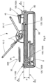
- FIG. 7A shows another scenario when using the present rat trap 1 where any faulty triggering is eliminated by means of the trigger plate 30 being configured for pushing and displacing an firing indicator 110 a certain or sufficient distance D out of contact with the striker bar 10 away from the prior art position in the upper right part view when the rat/mouse is pressed down by the striker bar 10 to avoid the faulty triggering as in the prior art rat trap, whereby the crushing and flattening of a small rat/mouse 200 in the present trap 1 does not incur a faulty triggering indication, i.e.
- the trigger plate 30 is configured such that wherever any flattened rat/mouse 200 presses down on the trigger plate, the striker bar 10 does not come into contact with the firing indicator 110 and no faulty triggering indication occurs.
- the trap 1 comprises at least one spring 2 configured for biasing/moving the striker bar 10 with a killing force when released due to triggering of the trap.
- the rodent trap 1 comprises a housing 3, see figs. 1 and 1A showing two aspects.
- the trap 1 is a modular system made up of separate detachable modules 4 to 7 as shown in figs. 3 to 5C .
- a module is configured to removably or fixedly mate with one or more of the other modules and functionally cooperate after all modules 4 to 7 are assembled together as the whole covering 3 making up the trap 1.
- at least three of the modules i.e. at least one removable upper part and/or outer upper casing/covering 4; at least one detachable outer bottom casing 5 and at least one inner inset 7 of figs. 1A , 4A , and 5A to 5C are configured to removably and/or exchangeably mate with one or more of the other modules, e.g. outer covering 6'.
- the trap housing 3 comprises a first module being a removable upper part and/or outer upper casing/covering 4, see figs. 1, 1A , and 3 .
- the trap housing 3 comprises a second module being at least one detachable outer bottom casing 5, see figs. 1, 1A , 3 , 4A , 5A , 5B and 5C .
- the trap housing 3 comprises a third module being at least one detachable inner insert 6 see the aspect of figs. 1 , 3 and 5 .
- the trap housing 3 comprises a third module being at least one detachable or fixated outer covering 6', see the aspect of figs. 1A and 5C .
- the trap housing 3 comprises a fourth module being at least one detachable inner inset 7 comprising the spring 2 and striker bar 10, see figs. 2A - 2CC , 4 , 5C and 6 .
- This inset 7 is the actual trap or killing unit of the striker trap 1.
- Modules 4, 5, 6 and 7 are each configured for detachable connection in a way similar to a Matryoshka/Babushka doll making the trap 1 possible to easily and quickly disassemble and assemble in the aspect of figs. 1 , 3 and 5 .
- the outer covering module 6' is also detachable in the same way or fixedly attached to the mouse/rat trap 1.
- the detachable inner insert 6 is configured for detachably fitting into the detachable outer bottom casing 5.
- the detachable inner inset 7 is configured for detachably fitting into the detachable inner insert 6 in the aspect of figs. 1 , 3 , 4 , and 5 .
- the detachable inner inset 7 is configured for detachably fitting into the detachable outer bottom casing 5 in the aspect of figs. 1A , 2A - 2CC , 4A , and 5A - 5C .
- the upper part and/or outer upper casing/covering 4 is configured, together with the detachable outer bottom casing 5, for detachably fitting over or enclosing at least the detachable inner insert 6 and the detachable inner inset 7 when assembling the rat trap 1 of figs.
- the detachable inner insert 6 of the aspect in figs. 1 , 3 , 4 , and 5 comprises one or more power sources 50, such as a battery, and one or more transmitters 60 for direct communication with other rat traps 1 having transmitting means and/or directly with a data base 70 and/or directly or via a central unit 80 and/or an internal controller 80' of the electronics and functions of one or mouse/rat traps 1 to one or more other rat traps and/or data bases 70 and/or other means for communication, see figs. 1 , 3 , 4 , 5 and 9 .
- the communication is achieved via wires or wirelessly between these entities 1, 60, 70, 80, 80'.
- the upper part and/or outer upper casing/covering 4 is configured, together with the detachable outer bottom casing 5 and outer covering/end/side wall 6', for detachably fitting over or enclosing at least the detachable inner inset 7 when assembling the rat trap 1 of figs. 1A , 2A - 2CC , 4A , and 5A - 5C making up the whole cover/hosuing 3.
- 1A , 2A - 2CC , 4A , and 5A - 5C comprises one or more power sources 50, such as a battery, and one or more transmitters 60 for direct communication with other rat or mouse traps 1 having transmitting means and/or directly with a data base 70 and/or directly or via a central unit 80 and/or an internal controller 80' of the electronics and functions of one or mouse/rat traps 1 to one or more other mouse/rat traps and/or data bases 70 and/or other means for communication, see figs. 1A , 2A - 2CC , 4A , and 5A - 5C and 9 . This communication is achieved via wires or wirelessly between these entities 1, 60, 70, 80, 80'.
- one or more of the rat traps 1 comprises a sensor 140 operatively connected to a controller 80' of the trap 1.
- This sensor 140 is in some aspects a movement and/or a presence sensor.
- This sensor 140 is e.g. a so-called passive infrared, PIR, sensor.
- the sensor 140 may also be a mechanically influenced contact/switch, a temperature sensor or another type of sensor.
- the sensor may emit an analog or digital signal directly to a controller 80' and/or the central unit 80 and/or to one or more rat traps 1, e.g. their controllers 80', and/or one or more data bases 70 and then indirectly to the central unit.
- the sensor 140 is powered in some aspects without being interrupted by the control unit 80' in order to thereby ensure detection of an event in the rat trap 1 when it occurs which, in some cases, may be a prerequisite for detection.
- the power supply to the sensor 140 is interrupted or reduced, optionally via a particular command to the sensor during those periods when the trap is in its sleep mode, e.g. to save/optimise current consumption for extending the battery powr and/or battery life.
- the sensor 140 sends signals concerning if a rat or mouse 200 is moving/has been moving in the rat trap 1 to enable checking e.g. if bait must be added and/or changed and/or the rat trap must be emptied.
- the senor 140 is a camera or the like or is used together with a camera, whereby image recognition of pictures and/or video is/are used for control of the trap 1 and/or check of presence of pests 200 by detection of them.
- the sensor 140 is a microphone or the like or a microphone is used together with the sensor 140 and/or a camera, whereby sound and/or image/video recognition is/are used for control of the trap 1 and/or check of presence of pests 200 by detection of them.
- the rat trap 1 is a spring-loaded strike trap comprising the at least one spring 2 configured for biasing the striker bar 10 from a first start or armed position A to at least one other and/or intermediary/end/second position B, C.
- the rat trap 1 is a spring-loaded strike trap comprising the at least one other movable bar 20 configured for indicating/securing arming of the rat trap 1 by being configured for releasable attachment to a second start or armed position A'.
- the rat trap 1 is a spring-loaded strike trap comprising the spring 2 configured for biasing the movable arming bar 20 from its start position A' to at least one other and/or intermediary/second/end position B', C'.
- the start/armed positions A, A' for the striker bar 10 and the movable arming bar 20, respectively, are positions where the rat trap 1 is armed, i.e. the rat trap is not yet triggered.
- the other and/or intermediary/end/second positions B, B', C, C' for the striker bar 10 and movable arming bar 20, respectively, are positions where the rat trap 1 has been triggered by means of the trigger plate 30 and a trigger 40 or by other means/reasons and the bars 10, 20 have been released and moved or swiped or rotated or turned quickly from their respective start/armed positions A, A' into a physically other position B, B', C, C', respectively. This is common for all aspects.
- the trigger 40 comprises a first or release end 40A configured for releasably holding the arming bar 20 and a second or anvil or holder end 40B for eleasably holding the trigger plate 30.
- the trigger plate 30 comprises a first end 30A arranged at one end 8D of the bottom plate 8.
- the trigger plate 30 comprises a second end 30B adjacent the second trigger end 40B and configured to be releasably held/engaged by this trigger end 40B such that when the first trigger plate end 30A is pressed down, e.g.
- the first trigger end 40A is shaped similar to a hook that is hooked over the arming bar 20 in the armed position A'.
- the trigger 40 is configured to rotate or turn or pivot around an axis T, see fig. 8A . This is common for all aspects.
- Each start position A, A' is an original/initial position for each bar 10, 20 while each end position B, B' for each bar is the final or stop position for each bar after triggering the rat trap 1, i.e. after the bars are released and then moved a maximum distance or angle as each bar is pivoted or rotated or turned into these final positions before being rearmed again.
- the intermediary positions C, C' for each bar 10, 20 are positions where the striker bar 10 has hit a rodent, e.g. a rat or mouse, and then been stopped in its movement at its intermediary position C before reaching its maximum or final or end position B.
- the arming bar 20 is usable as a handle configured for pushing the arming bar (and the striker bar 10 simultaneosuly) back in the opposite direction of its movement when released into their arming positions A, A' again and releasably locking the arming bar in place by means of the trigger 40 charging the rat trap 1. This is common for all aspects.
- the striker bar 10 and arming bar 20 are configured for synchronised movements when released.
- the striker bar 10 and arming bar 20 is in aspect different ends of the same metal bar.
- the striker bar 10 and arming bar 20 is in another aspect different ends of the same metal bar being shaped as a soccer goal.
- the metal bar is an elongated metal wire formed into a rectangular plane hollow shape and then formed/bent about an axis in parallel with the plane of the rectangular hollow shape.
- the striker bar 10 forms a U-shaped metal wire that transcends or extends into another U-shaped metal wire being the arming bar 20 with an angle ⁇ therebetween ( fig. 7B ).
- the U-shaped striker bar 10 and the U-shaped arming bar 20 then extends from each other with the angle ⁇ between them being between about 80° to 120°.
- the angle ⁇ is in this case an bending angle but could be made by other methods than bending, e.g. making striker bar 10 a separate U-shaped bar and weld it at its ends, at an angle ⁇ , to the ends of the arming bar 20 being another separate U-shaped bar.
- the movable arming bar 20 is in contact with a first stop or end anvil or end/first indicator 100 in the aspect of figs. 1 , 3 , 4 , and 5 or a first stop or end anvil or end/first indicator 101 in the aspect of figs. 1A , 2A - 2CC , 4A , and 5A - 5C with a purpose of indicating that the rat trap 1 is armed, i.e. that the rat trap is not yet triggered but ready for use.
- the only difference between the first indicator 100 of the former aspect above and the first indicator 101 of the latter aspect above is their orientation or position, i.e. they have both the same function.
- the former first indicator 100 is extending in full in parallel with the direction of movement of the striker bar 10 (and in parallel with the longitudinal directions of the other indikators 110 and 120, see below and figs. 2A to 2C ) while the latter first indicator 101 is extending partly in parallel with the direction of movement of the striker bar 10 (and partly in parallel with the longitudinal directions of the other indikators 110 and 120, see below and figs. 2AA to 2CC ) but has a first end or end part 101A that changes direction about or exactly 90°, i.e. this end 101A extends perpendicular into a free end adapted for contact with the arming bar 20 as for the former first indicator 100).
- the other position C for the striker bar 10 is a second position and/or an intermediary end position where the rat trap 1 has been triggered and the striker/killing bar 10 has been released and moved or swiped or rotated or turned quickly from its start position A into a physical other position C hitting a rat/mouse and killing it, thereby ending, i.e. being stopped in its movement against the body of the rat/mouse 200.
- the other and/or end/second position B is an end position where the rat trap 1 has been triggered and the striker bar 10 has been released and moved or swiped or rotated or turned quickly from the start position A into a physical other position B not hitting a rat/mouse and thereby not killing it and ending/being stopped in its movement at this physical other position B by mistake, i.e. unintentionally, e.g. due to an error.
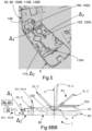
- the striker bar 10 is in contact with a second stop or second end anvil or second end/second indicator 110 closing a circuit between the end indicator 110 of fig. 8C and the third indicator 120 of fig. 8A via killing bar 10 and spring 2 and connection P.
- each of these indicators 100, 101 and 110 are configured for closing an electric circuit with the third indicator 120 of fig. 8A via spring 2 and connection P when the striker bar 10 and arming bar 20 comes into contact with its indicator in positions A' and B above and shown in figs. 2A to 2CC , 4 , 4A , 5C , 6 , 7A , 7B , 8A , 8B , 8BB and 8C .
- the spring 2 of the mouse/rat trap 1 is a spring configured for primarily biasing/loading the strike bar 10, such that it is very swiftly swept/moved and hits the rat/mouse with enough force for a quick kill when the trap 1 is triggered.
- the spring 2 of the rat trap 1 comprises a first end 2A.
- the first spring end 2A is configured for being in conductive/electrical contact with a third indicator 120 shown in figs. 8A , this indicator 120 is the same for both aspects of figs. 1 , 2A - 2C , 3, 4 , and 5 , and 1A , 2A - 2CC , 4A , and 5A - 5C , respectively, the same goes for the second end/second indicator 110.
- the trap 1 is adapted for being placed adjacent or against or in contact with or at a distance from a vertical object, such as a wall or the like.
- the striker trap 1 is adapted for standing on a horisontal layer or surface or floor or the like.
- the trap 1 may be partly attached to the vertical wall/section and/or the horisontal layer/floor if an enhanced stability of the striker trap is desired, but such attachment is not necessary in all applications, i.e. the trap is able to be fully free-standing in a stable way.
- the spring-loaded strike trap 1 comprises the at least one spring 2, the housing 3, the at least one striker bar 10, the at least one arming bar 20, the at least one trigger plate 30, and the at least one trigger 40.
- the arming bar 20 and the trigger plate 30 is releasably held by the trigger 40 (see figs. 2A to 2CC , and 8A to 8C / 8BB ) in the first positions A, A'.
- the arming bar 20 and the trigger plate 30 is releasably held by the trigger 40 in contact with the ready indicator 100, 101 in the first positions A, A' (see figs. 2A to 2CC and 8A to 8C / 8BB ).
- the ready indicator 100, 101 indicates that the spring-loaded strike trap 1 is armed/charged by closing a circuit formed between the ready indicators 100, 101 of figs. 8B and 8BB and the third indicator 120 via arming bar 20 and spring 2 and connection P.
- the spring 2 is configured for biasing the bars 10, 20 to move from their first positions A, A' into the at least one other position B, B', C, C', where the bar movements are stopped, when/after the spring-loaded strike trap 1 is triggered releasing the bars.
- the striker bar 10 when the spring-loaded strike 1 trap is triggered releasing the striker bar, is either (releasably) biased by the spring 2 into contact with the firing indicator 110 in the final/end position B, if a rat or mouse 200 is not hit, or biased into contact with a rat or mouse 200 of a first/certain/predetermined size hitting and killing it in the intermediary position C not in contact with any of the indicators 100, 101, 110, wherein no circuit between arming/striking bars 10, 20 and spring 2 and connection P and the third indicator 120 is closed indicating a "catch" of a rat or mouse 200.
- the trap 1 and/or its components making it up can be made of non-wood related materials such as plastics, metal, e.g. aluminium etc. or a mixture of two or more of those materials as long as the parts for conductive/electrical connections provides reliable closing and opening of the electrical circuits as explained herein.
- the trap 1 and its parts 4 to 7 and 10 to 40 and 100 to 120 are made of recycleable materials.
- the spring 2; pivot axis P; striker bar 10; arming bar 20; ready indicators 100, 101; firing indicator 110 and the other/third indicator or energiser 120 are at least partly conductive and/or made of conductive material to enable closing and cutting electric circuits depending on their positions and to which entities they are in conductive connection.
- the spring 2, the pivot axis P, striker bar 10, the arming bar 20, the ready indicator 100/101, the firing indicator 110 and the other/third indicator or energiser 120 are at least partly made of conductive metal.
- the trigger plate 30 is configured for engaging the firing indicator 110 to displace the firing indicator a distance D (see fig. 7A ), as measured in the direction of trigger plate movement.
- This displacement D of the firing indicator 110 when a rat/mouse 200 having a second size/being smaller than the first/certain/predetermined size is hit by the striker bar 10, away from its location when the striker bar is in its final/end position B shown in upper right part view of fig. 7A with the firing indicator 110 in solid lines in both this part view and the larger lower view of fig. 7A , towards another location where the firing indicator is not in contact with the striker bar 10 as shown with the firing indicator 110 in dotted lines in the larger lower view of fig. 7A similar to an intermediary position C for the striker bar 10.
- This function is common for all aspects.
- the firing indicator 110 and/or the ready indicator 100/101 and/or the energiser 120 is/are made of a flexible material and/or has a shape making it flexible.
- the firing indicator 110 and/or the ready indicator 100/101 and/or the energiser 120 is/are flat elongated metal strips as seen in figs. 2A , 2AA , 2C , 2CC , 3 , 5 , 5A to 5C , 6 , 7A, 7B , 8A, 8B , 8BB , and 8C . This is common for all aspects.
- the bottom plate 8 of the detachable inner inset 7 comprises an upper side 8A and lower side 8B.
- the trigger plate 30 is configured for being movably/pivotally attached to the upper bottom plate side 8A via the rotary/pivot axis P extending substantially in parallel or in parallel with the extension plane of the bottom plate or its bottom plate side.
- the bottom plate 8 of the detachable inner inset 7 has a plate shape defined by its upper side 8A and lower side 8B and two long sides 8C and two short sides 8D.
- the upper side 8A and lower side 8B are configured for forming substantially parallel and opposite planes extending substantially perpendicular to the long and short sides 8C, 8D.
- the long 8C and short 8D sides are configured for forming pairwise substantially parallel and opposite sides relative each other.
- the ready indicator 100/101 comprises a first end 100A/101A configured for being arranged at one of the short 8D or long 8C sides of the bottom plate 8 for conductive connection with the arming bar 20 when in its first position A' when the detachable inner inset 7 is assembled as a removable inner part or module into the trap 1.
- the ready indicator 100/101 comprises a second end 100B/101B configured for being arranged at one of the other short 8D or long 8C sides of the bottom plate 8 in conductive connection with the arming bar 20 when the detachable inner inset 7, i.e.
- the striking/killing unit is assembled as a removable inner part or inner module into the trap 1 as charged. This is common for all aspects.
- the indicators 100, 101, 110 and 120 are in some aspects part of the inner inset 7.
- the indicators 100, 101, 110 and 120 are in some aspects part of the detachable outer bottom casing 5.
- the indicators 100, 101, 110 and 120 are in some aspects parts of the detachable outer bottom casing 5 and the inner inset 7.
- the second indicator ends 100B, 101B, 110B, 120B are introduced into the end with electronics 50, 60, 80' of the detachable outer bottom casing 5 as seen in figs. 4A , 5C , and 8A - 8C / 8BB to be in operational/electrical connection with the electronics when assembling the inset 7 therein.
- the ready indicator 100/101 is configured for being arranged as a part of the detachable inner inset 7 (see figs. 2A-2C , 2AA-2CC , 7A-7B and 8A-8C / 8BB ) or the detachable inner insert 6 (see fig. 5 ) and/or the detachable outer bottom casing 5, the same goes for the firing indicator 110 and the energiser 120.
- the trigger plate 30 comprises a first end 30A adjacent the firing indicator 110 and a second end 30B at or closer to the ready indication 100/101.
- the second trigger plate end 30B has a shape such that its lower part is supported against the upper side 8A of the bottom plate 8 at a lower position than its first end 30A.
- the first trigger plate end 30A is a free end that can tilt downwards toward the firing indicator 110 when a rat/mouse 200 presses it down, but the other trigger plate end 30B hinders the first trigger plate end 30A from tilting upwards not more than into a horisontal position, i.e. the trigger plate 30 can tip its first end 30A below a horisontal level as seen in fig.
- the trigger plate 30 is kept horisontal by the trigger 40 and its second end 30B when no rat or mouse 200 presses it down and the trap 1 is charged, i.e. in its positions A, A' for the ready and firing indicators 100, 101, 110. This is common for all aspects.
- the ready indicator 100/101 and firing indicator 110 are elongated and flat and configured for extending from their first ends 100A, 101A, 110A at a position arranged on/at or above a first level ⁇ 1 defined as extending along the plane of the upper bottom plate side 8A, towards the lower plate side 8B and along this lower plate side at a second level ⁇ 2 defined as extending along the lower plate side towards and ending at their second ends 100B, 101B, 110B.
- the energiser 120 is elongated and flat configured for extending from a first end 120A at a position arranged on/at or above the first level ⁇ 1 of the upper bottom plate side 8A, towards the lower plate side 8B and along this lower plate side at the second level ⁇ 2 of the lower plate side towards and ending at a second end 120B.
- the indicators 100, 101, 110, 120 have different shapes and lengths but have at least one part extending lowest, i.e. extending along the second level ⁇ 2 to enable coming into contact with any water or the like conductive fluid when present to indicate excess water level, e.g. to alert a house owner of water or sewage leakage of the like. Figs.
- this second level ⁇ 2 is the same for the lowest part of all the indicators 100, 101, 110, 120 as seen in figs. 2A , 2AA , 2C , 2CC , 3 , 5 , 6 , 7A-7B , 8A-8C / 8BB , this being in particular clearly seen in figs. 2C and 2CC .
- This alignment of the indicators 100, 101, 110, 120 at the same second level ⁇ 2 ensures a secure and repeatable indication of excess water or the like conductive fluid. This is common for all aspects.
- a system/network 300 of traps 1 is schematically shown in fig. 9 where the traps are arranged at/in houses 90. However, one or more traps 1 could be placed in sewers or the like.
- This system or trap network comprises at least two traps 1. These at least two traps 1 are operatively connected to cooperate for eliminating or at least reducing or at least minimising a population of rats and/or mouses 200 in houses or before they reach the houses 90.
- These at least two traps 1 are configured to form a MESH network in which at least one and/or each and/or all traps continuously monitor presence of water or the like conductive fluid and that one or more of the traps is configured for registering if existing water or the like conductive fluid are at/over a certain/predetermined level, i.e. the second level ⁇ 2 by use of the indicators 100, 101, 110, 120 that are conductively connected forming a closed circuit when the water or the like conductive fluid has reached the certain/predetermined level ⁇ 2 .
- This is common for
- One or more or each or all traps 1 comprises a communication device 60, such as a transmitter 60 for sending associated signals by wire and/or wirelessly depending on the number of traps 1 in the network 300 and/or their distance to each other and/or directly to one or more databases 70 and/or a central/external/internal unit or control unit or controller 80, 80' that is operatively connected to the one or more data bases of fig. 9 (the sizes of the traps 1 and their equipment are not to scale in this figure and may be located under/below and/or outside and/or inside the houses 90 or sewers or the like).
- This communication between at least one trap 1 and at least one other trap 1 or directly between any of the traps 1 and the controller/-s 80/80' is achieveable in many ways nowadays with the widespread technology. This is common for all aspects.
- the principal functionality of the system/network 300 of traps 1 is enabled by one or more of the traps 1 being configured for registering if existing water or the like conductive fluid are at/over the certain/predetermined level ⁇ 2 also being operatively connected to the central unit 80 and/or internal trap controllers 80' which is optionally operatively connected to the at least one data base 70.
- the registering of the closing of the circuit of the indicators 100, 101, 110, 120 when the water or the like conductive fluid has reached the predetermined level ⁇ 2 is configured for triggering an alert signal (illustrated by lightning like arrows in fig.
- One or more of the traps 1 could be a master unit, i.e. a more intelligent trap 1.
- One or more traps 1 could be placed in remote locations in large areas, e.g. industrial and/or production areas where cable connections are disproportionately expensive, then wireless communication as shown in fig. 9 is preferred.
- Cable connections with power supply may, in some contexts, constitute a safety hazard caused by cable defects induced by e.g. pests, wherefore one or more batteries 50 in a trap 1 is preferred as power source.
- traps 1 for pest control it is desired, on the one hand, to achieve the longest possible service intervals between e.g. battery change or battery recharging to reduce costs.
- the wireless communication between the units 70, 80, 80' and traps 1, in the data network takes place in accordance with a network protocol, which may be a MESH network protocol or another open or proprietary protocol.
- the control unit/-s 80, 80' is/are therefore configured to implement the network protocol for executing transmission and repeater functionalities.
- control unit/-s 80 80' is/are provided with an identification code which is unique in the network 300 that the trap/-s 1 is/are part of.
- One or more of the traps could also comprise a controller 80' as part of its own electronics controlling the trap 1, e.g. as a part of the operational components being the battery 50 and/or another controller of the trap 1 and wireless transmitter 60, and cooperating/controlling these entities.
- the internal trap controller 80' and/or external control unit 80 of the network 300 could also be configured with a timer. Exemplary, during the period when the controller 80'/control unit 80 is in its normal mode, it transmits its report during a time interval whose start is determined by the identification code and sets the transmitter or radio transceiver 60 to act as repeater.
- the controller 80'/control unit 80 ensures that dispatch of the report is not interrupted by its repeater function, e.g. by using mutually non-overlapping respective time intervals.
- a wireless transmitter/radio transceiver 60 has a receiver circuit and a transmitter circuit. The circuits can be integrated with each other or can be separate circuits. They will often share the same antenna. When the radio transceiver 60 acts as repeater, it will often use the transmitter and receiver circuits alternatingly. When the radio transceiver 60 dispatches the report, there is a need for the transmitter circuit.
- the receiver circuit is used in a unit for listening in on ongoing transmissions, if any, from other controllers 80' and/or control units 80 and/or traps 1 before the controller 80'/control unit 80 and/or trap autonomously/itself starts its transmission by the transmitter circuit.
- a monitoring unit e.g. in operative connection with the internal trap controller 80' may be built integrally into a trap 1 to the effect that it constitutes, along with the trap, a trap that can be activated to be in wireless communication with other apparatuses and/or traps 1 in a data network.
- a monitoring unit can be made as a building-on or a building-in unit that is configured for being directly compatible with an existing trap 1 or compatible upon modification of the existing trap.
- Such a monitoring unit could also be a function of the internal trap controller 80' that monitors the indication of any excess water or the like by means of the indicators 100, 101, 110, 120.
- the radio transmitter 60 is configured for converting a signal from the control unit 80' of a trap 1, typically a digital signal, to an airborne radio-wave signal via an antenna.
- the radio transmitter transmits and receives on one or more selected radio frequencies, e.g. frequency bands in the range around eg 433 MHz, 868 MHz, 2.4 GHz, 5 GHz, and/or 5.8 GHz.
- the trap 1 optionally comprises a bait box 130 to lure the rodents 200.
Landscapes
- Life Sciences & Earth Sciences (AREA)
- Pest Control & Pesticides (AREA)
- Engineering & Computer Science (AREA)
- Insects & Arthropods (AREA)
- Wood Science & Technology (AREA)
- Zoology (AREA)
- Environmental Sciences (AREA)
- Catching Or Destruction (AREA)
Claims (19)
- Federbelastete Schlag-Nagetierfalle (1), umfassend mindestens eine Feder (2), ein Gehäuse (3), mindestens eine Anschlagschiene (10), mindestens eine Scharfstellschiene (20), mindestens eine Auslöserplatte (30) und mindestens einen Auslöser (40), wobei die Feder dazu konfiguriert ist, die Schienen (10, 20) vorzuspannen, damit sich diese aus einer ersten Position (A, A'), in der die Scharfstellschiene und die Auslöserplatte freigebbar durch den Auslöser gehalten werden und mit einer Bereitschaftsanzeige (100, 101) in Kontakt stehen, um anzugeben, dass die federbelastet Schlag-Nagetierfalle (1) geladen ist, in mindestens eine andere Position (B, B', C, C') bewegen, in der die Bewegung der Schienen angehalten wird, nachdem die federbelastete Schlag-Nagetierfalle ausgelöst wurde und die Schienen freigegeben hat, wobei die Anschlagschiene (10), wenn die federbelastete Schlag-Nagetierfall (1) ausgelöst wurde und die Schienen freigegeben hat, entweder durch die Feder (2) in Kontakt mit einer Abfeuerungsanzeige (110) in einer Abschluss-/Endposition (B) vorgespannt ist, wenn eine Ratte oder Maus (200) nicht getroffen wurde, oder in Kontakt mit einer Ratte oder Maus einer ersten/gewissen/vorbestimmten Größe vorgespannt ist, wodurch diese in einer Zwischenposition (C) getroffen und getötet wird, die nicht in Kontakt mit einer beliebigen der Anzeigen (100, 101, 110) steht,
dadurch gekennzeichnet, dass die Nagetierfalle (1) ferner einen Bewegungs- und/oder Anwesenheitssensor (140) umfasst, der zum Detektieren eines Nagetiers (200) angepasst ist, und dadurch, dass die Anzeigen (100, 101, 110, 120) leitend verbunden sind, um es der Nagetierfalle zu ermöglichen, eine Anwesenheit von Wasser oder einer/eines ähnlichen leitenden Flüssigkeit/Fluids durch Verwendung der Anzeigen kontinuierlich zu überwachen und zu detektieren, wodurch ein oder mehrere geschlossene Schaltkreise gebildet werden, wenn bestehendes Wasser oder die/das ähnliche leitende Flüssigkeit/Fluid auf/über einem gewissen/vorbestimmten Pegel (Δ2) liegt, wobei der Anwesenheitssensor (140) dazu konfiguriert ist, über eine Detektion einer Anwesenheit von einem oder mehreren Nagetieren (200) zu benachrichtigen, und die Anzeigen (100, 101, 110, 120) dazu konfiguriert sind - wenn ein geschlossener Schaltkreis gebildet ist - durch Emittieren eines oder mehrerer Signale von der Nagetierfalle (1) als Reaktion auf die Detektion(en) über eine Detektion einer Anwesenheit von überschüssigem Wasser oder der/des ähnlichen leitenden Flüssigkeit/Fluids zu benachrichtigen, zur direkten Kommunikation mit einer anderen Nagetierfalle (1) und/oder direkt mit einer Datenbank (70) und/oder direkt mit einer zentralen Einheit (80) und/oder einer internen Einheit (80') oder über diese an eine oder mehrere andere Nagetierfallen und/oder Datenbanken. - Nagetierfalle (1) nach einem der vorangehenden Ansprüche, wobei die Abfeuerungsanzeige (110) ein Leiter/aus einem leitenden Material gefertigt ist.
- Nagetierfalle (1) nach einem der vorangehenden Ansprüche, wobei die Bereitschaftsanzeige (100, 101) ein Leiter /aus einem leitenden Material gefertigt ist.
- Nagetierfalle (1) nach einem der vorangehenden Ansprüche, wobei sowohl die Anschlagschiene (10) als auch die Scharfstellschiene (20) aus einem leitenden Material gefertigt und dazu konfiguriert sind, in einer leitenden Verbindung mit derselben Dreh-/Schwenkachse (P) zu stehen.
- Nagetierfalle (1) nach Anspruch 4, ferner umfassend einen Energiespender (120), der dazu konfiguriert ist, in einer leitenden Verbindung mit derselben Dreh-/Schwenkachse (P) wie die Anschlagschiene (10) und die Scharfstellschiene (20) zu stehen.
- Nagetierfalle (1) nach einem der vorangehenden Ansprüche, wobei die Feder (2), die Anschlagschiene (10), die Scharfstellschiene (20), die Auslöserplatte (30) und der Auslöser (40) dazu konfiguriert sind, auf einer oberen Seite (8A) einer unteren Platte (8) angeordnet zu sein, um einen lösbaren inneren Einsatz (7) zu bilden, der dazu konfiguriert ist, ein getrenntes und/oder autonomes inneres Teil oder Modul des Fallengehäuses (3) darzustellen, wenn er darin eingebaut ist.
- Nagetierfalle (1) nach Anspruch 6, wobei die untere Platte (8) des lösbaren inneren Einsatzes (7) die obere Seite (8A) und eine untere Seite (8B) aufweist und die Auslöserplatte (30) dazu konfiguriert ist, über eine Dreh-/Schwenkachse (P), die sich im Wesentlichen parallel oder parallel zu der Verlängerungsebene der unteren Platte oder ihrer unteren Plattenseite erstreckt, bewegbar/schwenkbar an der oberen Seite (8A) der unteren Platte angebracht zu werden.
- Nagetierfalle (1) nach Anspruch 6 oder 7, wobei die untere Platte (8) des lösbaren inneren Einsatzes (7) eine Plattenform aufweist, die durch ihre obere Seite (8A) und untere Seite (8B) und zwei lange Seiten (8C) und zwei kurze Seiten (8D) definiert ist, die obere Seite und die untere Seite dazu konfiguriert sind, im Wesentlichen parallele und gegenüberliegende Ebenen zu bilden, die sich im Wesentlichen senkrecht zu der langen und kurzen Seite erstrecken, wobei die lange und kurze Seite dazu konfiguriert sind, im Wesentlichen parallele und gegenüberliegende Seiten bezogen aufeinander paarweise zu bilden, und die Bereitschaftsanzeige (100, 101) ein erstes Ende (100A, 101A) umfasst, das dazu konfiguriert ist, zur leitenden Verbindung mit der Scharfstellschiene (20), wenn diese sich in ihrer ersten Position (A') befindet, an einem von der kurzen (8D) oder langen (8C) Seite der unteren Platte angeordnet zu werden, wenn der lösbare innere Einsatz (7) als ein entfernbares inneres Teil oder Modul in die Nagetierfalle (1) eingebaut ist, wenn diese geladen ist.
- Nagetierfalle (1) nach Anspruch 8, wobei die Bereitschaftsanzeige (100, 101) ein zweites Ende (100B) umfasst, das dazu konfiguriert ist, in leitender Verbindung mit der Scharfstellschiene (20) an einer der anderen kurzen (8D) oder langen (8C) Seite der unteren Platte (8) angeordnet zu werden, wenn der lösbare innere Einsatz (7) als ein entfernbares inneres Teil oder inneres Modul in die Nagetierfalle (1) eingebaut ist, wenn diese geladen ist.
- Nagetierfalle (1) nach Anspruch 6 oder einem der Ansprüche 7 bis 9, wobei die Bereitschaftsanzeige (100, 101) und die Abfeuerungsanzeige (110) langgestreckt und dazu konfiguriert sind, sich von ihren ersten Enden (100A, 101A, 110A) in einer Position, die an/auf oder über einem ersten Pegel (Δ1) angeordnet ist, der so definiert ist, dass er sich entlang der Ebene der oberen Seite (8A) der unteren Platte erstreckt, in Richtung der unteren Plattenseite (8B) und entlang dieser unteren Plattenseite auf einem zweiten Pegel (Δ2) zu erstrecken, was als sich entlang der unteren Plattenseite in Richtung ihrer zweiten Enden (100B, 101B, 110B) erstreckend und an diesen endend definiert ist.
- Nagetierfalle (1) nach Anspruch 5 und einem der Ansprüche 6 bis 10 in Abhängigkeit von Anspruch 5, wobei der Energiespender (120) langgestreckt und dazu konfiguriert ist, sich von einem ersten Ende (120A) in einer Position, die an/auf oder über dem ersten Pegel (Δ1) der oberen Seite (8A) der unteren Platte angeordnet ist, in Richtung der unteren Plattenseite (8B) und entlang dieser unteren Plattenseite an dem zweiten Pegel (Δ2) der unteren Plattenseite in Richtung eines zweiten Endes (120B) zu erstrecken und an diesem zu enden.
- Nagetierfalle (1) nach Anspruch 11, wobei der Energiespender (120) dazu konfiguriert ist, in leitender Verbindung mit der Scharfstellschiene (20) an der Schwenkachse (P) angeordnet zu werden, wenn die Nagetierfalle (1) geladen ist, und in leitender Verbindung mit einer Leistungsquelle und/oder einer Steuereinheit (50, 80'), wenn der lösbare innere Einsatz (7) als ein entfernbares Teil oder inneres Modul in die Nagetierfalle (1) eingebaut ist, und dazu konfiguriert ist, in leitender Verbindung mit der Anschlagschiene (10) zu stehen, wenn die Nagetierfalle ausgelöst ist und die Anschlagschiene freigegeben wurde und in leitenden Kontakt mit der Abfeuerungsanzeige (110) gekommen ist, und dazu konfiguriert ist, in leitender Verbindung mit der Bereitschaftsanzeige (100, 101) und der Abfeuerungsanzeige (110) zu stehen, wenn Wasser oder das ähnliche leitende Fluid den zweiten Pegel (Δ2) erreicht hat.
- Nagetierfalle (1) nach einem der vorhergehenden Ansprüche, wobei es sich bei dem Bewegungs- und/oder Anwesenheitssensor (140) um einen sogenannten passiven Infrarotsensor (PIR-Sensor) und/oder einen mechanisch beeinflussten Kontakt/Schalter und/oder einen Temperatursensor und/oder eine Kamera und/oder ein Mikrofon handelt.
- Nagetierfalle (1) nach einem der Ansprüche 6 bis 13, ferner umfassend eine äußere Abdeckung (6') im zusammengebauten Zustand, die dazu konfiguriert ist, den lösbaren inneren Einsatz (7) mindestens entfernbar oder fest abzudecken, wenn die Nagetierfalle (1) zusammengebaut ist, und/oder eine Leistungsquelle (50) und/oder eine interne Fallensteuerung (80').
- System/Netzwerk (300) mit Nagetierfallen (1), umfassend mindestens zwei Nagetierfallen (1) nach einem der vorangehenden Ansprüche, wobei diese mindestens zwei Nagetierfallen (1) wirkverbunden sind, um zum Eliminieren oder mindestens Reduzieren oder mindestens Minimieren einer Population von Raten und/oder Mäusen (200) zusammenzuwirken, dadurch geke nnzeichnet, dass diese mindestens zwei Nagetierfallen (1) dazu konfiguriert sind, ein MESH-Netzwerk zu bilden.
- System (300) mit Nagetierfallen (1) nach Anspruch 15, wobei die eine oder mehreren der Nagetierfallen (1), die dazu konfiguriert sind, zu erkennen, wenn bestehendes Wasser oder das ähnliche leitende Fluid auf/über einem gewissen/vorbestimmten Pegel (Δ2) liegen, mit einer zentralen Einheit (80) wirkverbunden sind und mit dieser in kommunikativer Verbindung stehen, wobei das Erkennen des Schließen des Schaltkreises/der Schaltkreise der Anzeigen (100, 101, 110, 120), wenn das Wasser oder das ähnliche leitende Fluid den vorbestimmten Pegel (Δ2) erreicht hat, dazu konfiguriert ist, ein Warnsignal auszulösen, das überschüssiges Wasser/leitendes Fluid angibt, das - drahtgebunden und/oder drahtlos - zu einer oder mehreren der anderen Nagetierfallen (1) und/oder eine Datenbank (70) und/oder die zentrale Einheit (80) gesendet wird, die alle der Nagetierfallen und ihre Funktionalität überwacht, wobei die zentrale Einheit dazu konfiguriert ist, zugeordnetes Personal über ein Wasser/Abwasserleck oder dergleichen zu benachrichtigen.
- System (300), umfassend eine Nagetierfalle (1) nach einem der Ansprüche 1 bis 14 und eine zweite Nagetierfalle (1) nach einem der Ansprüche 1 bis 14, wobei jede von der ersten und der zweiten Nagetierfalle (1) eine interne Steuerung (80') umfasst und die erste oder die zweite Nagetierfalle eine Mastereinheit ist, wobei die erste und die zweite Falle angeordnet sind, um drahtgebunden und/oder drahtlos miteinander zu kommunizieren.
- Verfahren zum Verwenden einer oder mehrerer federbelasteter Schlagfallen (1) nach einem der Ansprüche 1 bis 14 zum Überwachen und Detektieren einer Anwesenheit eines Nagetiers (200) oder Benachrichtigen über eine Anwesenheit davon und/oder Detektieren/Erkennen eines Fangs eines Nagetiers und/oder der Anwesenheit von überschüssigem Wasser und/oder Abwasser oder der/des ähnlichen leitenden Flüssigkeit/Fluids im Gebrauch und Übertragen/Senden eines Signals als Reaktion auf die Detektion(en) zur direkten - drahtgebundenen und/oder drahtlosen - Kommunikation mit einer oder mehreren anderen Nagetierfallen (1) und/oder direkt mit einer Datenbank (70) und/oder direkt mit einer zentralen Einheit (80)/internen Steuerung (80') und/oder über eine zentrale Einheit (80)/interne Steuerung (80') an eine oder mehrere andere Nagetierfallen (1) und/oder Datenbanken (70).
- Verfahren zum -drahtgebundenen und/oder drahtlosen - Erlangen eines oder mehrerer Signale von einer Nagetierfalle (1) nach einem der Ansprüche 1 bis 14, die eine Anwesenheit eines Nagetiers (200) und/oder einen Fang eines Nagetiers angibt, und/oder zum -drahtgebundenen und/oder drahtlosen - Erlangen eines oder mehrerer Signale von einer Nagetierfalle (1) nach einem der Ansprüche 1 bis 14, die angeben, wenn Wasser oder ein ähnliches leitendes Fluid einen vorbestimmten Pegel (Δ2) erreicht hat, und Benachrichtigen eines zugeordneten Personals über die Anwesenheit eines Nagetiers und/oder den Fang eines Nagetiers und/oder ein Leck von Wasser oder dem ähnlichen leitenden Fluid.
Applications Claiming Priority (3)
| Application Number | Priority Date | Filing Date | Title |
|---|---|---|---|
| DKPA201970443A DK180462B1 (en) | 2019-07-05 | 2019-07-05 | Rodent trap |
| PCT/EP2020/067184 WO2021004761A1 (en) | 2019-07-05 | 2020-06-19 | Rodent trap |
| EP20735285.7A EP3993624B1 (de) | 2019-07-05 | 2020-06-19 | Nagerfalle |
Related Parent Applications (1)
| Application Number | Title | Priority Date | Filing Date |
|---|---|---|---|
| EP20735285.7A Division EP3993624B1 (de) | 2019-07-05 | 2020-06-19 | Nagerfalle |
Publications (3)
| Publication Number | Publication Date |
|---|---|
| EP4364564A2 EP4364564A2 (de) | 2024-05-08 |
| EP4364564A3 EP4364564A3 (de) | 2024-06-05 |
| EP4364564B1 true EP4364564B1 (de) | 2025-06-11 |
Family
ID=71401716
Family Applications (2)
| Application Number | Title | Priority Date | Filing Date |
|---|---|---|---|
| EP20735285.7A Active EP3993624B1 (de) | 2019-07-05 | 2020-06-19 | Nagerfalle |
| EP24166016.6A Active EP4364564B1 (de) | 2019-07-05 | 2020-06-19 | Nagetierfalle |
Family Applications Before (1)
| Application Number | Title | Priority Date | Filing Date |
|---|---|---|---|
| EP20735285.7A Active EP3993624B1 (de) | 2019-07-05 | 2020-06-19 | Nagerfalle |
Country Status (10)
| Country | Link |
|---|---|
| US (2) | US12575555B2 (de) |
| EP (2) | EP3993624B1 (de) |
| AU (2) | AU2020311551B2 (de) |
| CO (1) | CO2022001064A2 (de) |
| DK (3) | DK180462B1 (de) |
| ES (2) | ES2982134T3 (de) |
| FI (2) | FI4364564T3 (de) |
| MY (1) | MY209577A (de) |
| PT (2) | PT3993624T (de) |
| WO (1) | WO2021004761A1 (de) |
Families Citing this family (6)
| Publication number | Priority date | Publication date | Assignee | Title |
|---|---|---|---|---|
| US20210169065A1 (en) * | 2017-01-06 | 2021-06-10 | Bayer Cropscience Lp | Sensor for a wireless animal trap detection system |
| SE543735C2 (en) * | 2019-10-11 | 2021-07-06 | Alert House Aps | A rodent trap configured to detect at least three distances |
| WO2021171319A1 (en) * | 2020-02-28 | 2021-09-02 | Aiot Elements Private Limited | Intelligent rodent management system |
| WO2023170219A1 (en) * | 2022-03-10 | 2023-09-14 | Anticimex Innovation Center A/S | A system for monitoring rodents in a sewage system, a monitoring device and methods related there to |
| USD1093539S1 (en) * | 2023-12-31 | 2025-09-16 | Julian Chambers | Rodent trap enclosure |
| NL2037555B1 (en) * | 2024-04-26 | 2025-11-11 | Attack B V | Detection system for an animal trap for mice and rats |
Family Cites Families (78)
| Publication number | Priority date | Publication date | Assignee | Title |
|---|---|---|---|---|
| US1588083A (en) * | 1924-10-29 | 1926-06-08 | Willard J Worsley | Animal trap |
| US1891737A (en) * | 1928-03-02 | 1932-12-20 | Herbert A Stilson | Animal trap |
| US2616211A (en) * | 1947-05-22 | 1952-11-04 | Triple E Mfg Company | Mousetrap |
| US2517928A (en) * | 1947-08-04 | 1950-08-08 | Lewis I Richards | Animal trap |
| US4665644A (en) * | 1986-03-11 | 1987-05-19 | Lubomir Vajs | Mouse and rat trap |
| US4711049A (en) * | 1986-09-25 | 1987-12-08 | Kness Manufacturing Co., Inc. | Animal trap |
| US4719718A (en) * | 1987-05-21 | 1988-01-19 | Kon Robert T | Electrically operated animal trap |
| US5001857A (en) * | 1989-08-14 | 1991-03-26 | Mcdaniel Howard J | Animal trap |
| US5148624A (en) * | 1991-04-10 | 1992-09-22 | Schmidt George A | Mousetrap |
| US5172512A (en) * | 1991-08-19 | 1992-12-22 | Sterling Drug, Inc. | Trap for catching mice and rats |
| US5154017A (en) * | 1991-12-16 | 1992-10-13 | Disalvo Herbert R | Rodent trap with signal |
| US6137415A (en) * | 1998-03-12 | 2000-10-24 | Rastar Corporation | Audio signal for spring-loaded rodent traps |
| US6415544B1 (en) * | 2000-04-28 | 2002-07-09 | Bell Laboratories, Inc. | Rodent trap with entrapping teeth |
| US6508031B1 (en) * | 2001-10-26 | 2003-01-21 | Bell Laboratories, Inc. | Rodent trap with removable bait container |
| US20030110679A1 (en) * | 2001-12-19 | 2003-06-19 | Steve Collins | Apparatus and method for the asthetic and unobtrusive trapping and disposing of rodents |
| US6655077B1 (en) * | 2002-07-17 | 2003-12-02 | Jose Trevino | Trap for a mouse |
| US20040020100A1 (en) * | 2002-08-05 | 2004-02-05 | O'brien Denis Michael | Apparatus for a wireless animal trap detection system |
| US6807767B1 (en) | 2003-10-22 | 2004-10-26 | James Frederick Schade | Small animal trap with infrared trigger |
| DE202005009127U1 (de) * | 2005-06-06 | 2005-12-01 | Urbanguard Gmbh | Schlagfalle für kleine Nagetiere, insbesondere für Mäuse und Ratten |
| GB0517917D0 (en) | 2005-09-03 | 2005-10-12 | Riwa Ltd | A bait box |
| US20090151221A1 (en) * | 2007-12-14 | 2009-06-18 | Daley James D | Signaling rodent trap system |
| US8026822B2 (en) * | 2008-09-09 | 2011-09-27 | Dow Agrosciences Llc | Networked pest control system |
| AU2014203633C1 (en) | 2008-09-09 | 2018-03-08 | Corteva Agriscience Llc | Networked pest control system |
| US8156683B2 (en) | 2009-07-09 | 2012-04-17 | David Slotnick | Wireless rat trap movement detection system |
| US8291637B2 (en) * | 2009-09-25 | 2012-10-23 | B&G Equipment Company | Rodent trap including presence indicator mechanism |
| US8490322B2 (en) * | 2010-07-16 | 2013-07-23 | Oms Investments, Inc. | Animal trap with collapsible arm |
| AU2011250776B2 (en) * | 2010-11-18 | 2014-03-20 | Round Point Peg Company Pty Ltd | Animal trap |
| US8793929B1 (en) * | 2011-03-21 | 2014-08-05 | Bell Laboratories, Inc. | Internal ballasted rodent bait station |
| US9210924B1 (en) * | 2012-03-27 | 2015-12-15 | Ty Terrell | Ecofriendly maritime pest management kit |
| US9258990B1 (en) * | 2012-08-21 | 2016-02-16 | Ralph Harvey | Rodent trap system with alarm |
| US20140085100A1 (en) * | 2012-09-25 | 2014-03-27 | Woodstream Corporation | Wireless notification system and method for electronic rodent traps |
| US20140300477A1 (en) * | 2012-09-25 | 2014-10-09 | Woodstream Corporation | Wireless notification systems and methods for electronic rodent traps |
| DK3151661T3 (da) * | 2014-06-03 | 2023-05-15 | Anticimex Innovation Center As | Indretning til skadedyrskontrol med kommunikationsmidler |
| US20180235205A1 (en) * | 2014-11-04 | 2018-08-23 | Dow Agrosciences Llc | Pest control system and method of operating same |
| CA2978584C (en) * | 2014-11-21 | 2023-03-21 | Larry Covington | Pest-management apparatuses with separator to improve function of rodent sensor |
| US9737069B1 (en) * | 2015-07-03 | 2017-08-22 | Eddie L. Giles, Jr. | Rodent trap with glue |
| CA2992645C (en) | 2015-07-21 | 2023-06-20 | Smart Wave Technologies Corp. | A pest control monitoring system |
| WO2017036480A1 (en) | 2015-08-31 | 2017-03-09 | Cb Svendsen A/S | Method for monitoring one or more pet traps, such as rat traps |
| CN106922646A (zh) * | 2015-12-30 | 2017-07-07 | 章玺 | 一种捕鼠夹和识别其状态的设备及方法 |
| US10531653B2 (en) * | 2016-02-03 | 2020-01-14 | Iot Sense, Llc | Pest trap monitor |
| US9861091B2 (en) * | 2016-02-22 | 2018-01-09 | Jay S. Derman | Snap trap actuator |
| WO2017149163A1 (en) | 2016-03-04 | 2017-09-08 | Arctic Systems Aps | A monitoring device for a snap trap |
| DK3298891T3 (da) * | 2016-09-22 | 2019-10-21 | Camro As | Klapfældeindelukke tilpasset til at reducere utilsigtet fangst |
| IT201600097486A1 (it) * | 2016-09-28 | 2018-03-28 | Italsia Millennium S N C | Trappola per topi di tipo etico |
| US9980477B2 (en) * | 2016-10-25 | 2018-05-29 | Michael McGrade | Vertical trap |
| US20180125056A1 (en) * | 2016-11-08 | 2018-05-10 | Michael G. Hetman | Rodent trap |
| US20180132474A1 (en) * | 2016-11-17 | 2018-05-17 | William Thomas Webster | Mousetrap apparatus |
| US20210169065A1 (en) * | 2017-01-06 | 2021-06-10 | Bayer Cropscience Lp | Sensor for a wireless animal trap detection system |
| MX2019008309A (es) * | 2017-01-10 | 2020-01-30 | Oms Investments Inc | Trampa de roedor con plataforma giratoria. |
| EP3351099A1 (de) * | 2017-01-18 | 2018-07-25 | Soren Fisker ApS | Schlagfallengehäuse mit fallenfreigabeindikator |
| GB201702274D0 (en) * | 2017-02-10 | 2017-03-29 | Bougie Normand | Device for getting rid of undesirable animals |
| CN108522492A (zh) * | 2017-03-03 | 2018-09-14 | 杨光献 | 一种无专用触发机关且可调节灵敏度捕鼠夹 |
| NL2018579B1 (nl) * | 2017-03-24 | 2018-10-03 | Maarten Crezee Hendrik | Val voor het vangen van dieren, in het bijzonder muizen |
| US11178864B2 (en) * | 2017-04-28 | 2021-11-23 | Ron Petrous | Pre-loaded bait rodent trap |
| US10743531B2 (en) * | 2017-05-03 | 2020-08-18 | Keven Walter Jones | Wireless rodent trap sensor |
| US11800863B2 (en) * | 2017-05-10 | 2023-10-31 | Vm Products, Inc. | Rodent trap with presence indicator mechanism |
| GB201708087D0 (en) * | 2017-05-19 | 2017-07-05 | Pelsis Ltd | Rodent Station |
| GB201708092D0 (en) * | 2017-05-19 | 2017-07-05 | Pelsis Ltd | Rodent station |
| WO2019040648A1 (en) * | 2017-08-22 | 2019-02-28 | Vm Products, Inc. | METHODS AND SYSTEMS FOR CONTROLLING HARMFUL ORGANISMS |
| US10440944B2 (en) * | 2017-11-20 | 2019-10-15 | Dennis LaRoque | Smart micro-mouse trap |
| US20190223430A1 (en) * | 2018-01-19 | 2019-07-25 | Dennis Theriault | Device for trapping and killing rodents |
| US20190343108A1 (en) * | 2018-01-19 | 2019-11-14 | Dennis Theriault | Device for trapping and killing rodents |
| US10888083B2 (en) * | 2018-02-09 | 2021-01-12 | Agmar Tools 2000 Limited | Animal trap |
| US20200329691A1 (en) * | 2018-02-26 | 2020-10-22 | Charlene F. Chessum | Heated and/or Cooled Rodent Trap |
| US11317619B2 (en) * | 2018-05-15 | 2022-05-03 | Ecolab Usa Inc. | Pest control device mounting system |
| US12171213B2 (en) * | 2018-07-03 | 2024-12-24 | Swissinno Solutions Ag | Rodent trap, system for refilling a rodent trap and method of refilling a rodent trap |
| US11528900B2 (en) * | 2018-07-06 | 2022-12-20 | Woodstream Corporation | Wash down sensor for electronic rodent traps and method of preventing false triggering using a wash down sensor |
| US11470836B2 (en) * | 2018-07-25 | 2022-10-18 | Woodstream Corporation | Rodent snap trap interfaced with electronics monitoring system and method of interfacing a snap trap with electronics monitoring system |
| US10477854B1 (en) * | 2018-10-19 | 2019-11-19 | Qianming Yang | Mousetrap with alarming and reminding functions |
| US11337416B1 (en) * | 2018-10-22 | 2022-05-24 | Bell Laboratories, Inc. | Remote sensing mechanical rodent trap |
| WO2020086716A1 (en) * | 2018-10-23 | 2020-04-30 | Ap&G Co., Inc. | Multi-catch rodent and insect trap |
| GB2578734A (en) * | 2018-11-05 | 2020-05-27 | Rentokil Initial 1927 Plc | Rodent traps |
| US10524464B1 (en) * | 2019-03-06 | 2020-01-07 | Paul F. Cook | Mouse trap |
| US10667508B1 (en) * | 2019-03-06 | 2020-06-02 | Paul F. Cook | Mouse trap |
| US20200315156A1 (en) * | 2019-04-02 | 2020-10-08 | Nicholas Giacia | Sanitary Mousetrap Housing Apparatus |
| US20200329692A1 (en) * | 2019-04-19 | 2020-10-22 | AP&G Co. Inc. | Rodent trap with enhanced attractants |
| US11477979B2 (en) * | 2019-10-01 | 2022-10-25 | Woodstream Corporation | Snap trap with set-prevent interference member and rodent orienting side walls |
| SE543735C2 (en) * | 2019-10-11 | 2021-07-06 | Alert House Aps | A rodent trap configured to detect at least three distances |
-
2019
- 2019-07-05 DK DKPA201970443A patent/DK180462B1/en active IP Right Grant
-
2020
- 2020-06-19 PT PT207352857T patent/PT3993624T/pt unknown
- 2020-06-19 DK DK20735285.7T patent/DK3993624T3/da active
- 2020-06-19 US US17/624,407 patent/US12575555B2/en active Active
- 2020-06-19 ES ES20735285T patent/ES2982134T3/es active Active
- 2020-06-19 AU AU2020311551A patent/AU2020311551B2/en active Active
- 2020-06-19 ES ES24166016T patent/ES3036443T3/es active Active
- 2020-06-19 MY MYPI2021007885A patent/MY209577A/en unknown
- 2020-06-19 EP EP20735285.7A patent/EP3993624B1/de active Active
- 2020-06-19 FI FIEP24166016.6T patent/FI4364564T3/fi active
- 2020-06-19 DK DK24166016.6T patent/DK4364564T3/da active
- 2020-06-19 PT PT241660166T patent/PT4364564T/pt unknown
- 2020-06-19 EP EP24166016.6A patent/EP4364564B1/de active Active
- 2020-06-19 FI FIEP20735285.7T patent/FI3993624T3/fi active
- 2020-06-19 WO PCT/EP2020/067184 patent/WO2021004761A1/en not_active Ceased
-
2022
- 2022-02-01 CO CONC2022/0001064A patent/CO2022001064A2/es unknown
-
2025
- 2025-09-17 US US19/331,511 patent/US20260013493A1/en active Pending
- 2025-11-05 AU AU2025263782A patent/AU2025263782A1/en active Pending
Also Published As
| Publication number | Publication date |
|---|---|
| DK180462B1 (en) | 2021-05-06 |
| US12575555B2 (en) | 2026-03-17 |
| FI4364564T3 (fi) | 2025-07-31 |
| ES2982134T3 (es) | 2024-10-14 |
| EP3993624B1 (de) | 2024-03-27 |
| PT3993624T (pt) | 2024-07-02 |
| CO2022001064A2 (es) | 2022-03-08 |
| DK3993624T3 (da) | 2024-06-17 |
| EP4364564A2 (de) | 2024-05-08 |
| PT4364564T (pt) | 2025-07-22 |
| DK201970443A1 (en) | 2021-02-10 |
| US20220346366A1 (en) | 2022-11-03 |
| WO2021004761A1 (en) | 2021-01-14 |
| AU2020311551A1 (en) | 2022-02-24 |
| FI3993624T3 (fi) | 2024-07-01 |
| MY209577A (en) | 2025-07-23 |
| EP3993624A1 (de) | 2022-05-11 |
| ES3036443T3 (en) | 2025-09-18 |
| US20260013493A1 (en) | 2026-01-15 |
| AU2020311551B2 (en) | 2025-12-18 |
| NZ784502A (en) | 2025-10-31 |
| DK4364564T3 (da) | 2025-07-14 |
| AU2025263782A1 (en) | 2025-11-27 |
| EP4364564A3 (de) | 2024-06-05 |
Similar Documents
| Publication | Publication Date | Title |
|---|---|---|
| EP4364564B1 (de) | Nagetierfalle | |
| JP6710203B2 (ja) | 害虫/害獣防除システム及びその動作方法 | |
| JP7053629B2 (ja) | 無線式動物捕獲器検出システム用センサ | |
| US20250351813A1 (en) | Pest control system and method of operating same | |
| US20220159941A1 (en) | Electronic Rodent Trap With Remote Monitoring Capability | |
| EP3076786B1 (de) | Falle | |
| EP4570067A2 (de) | Nagerfalle | |
| WO2018087247A1 (en) | A trap | |
| CA3147305C (en) | Electronic rodent trap with remote monitoring capability | |
| WO2025237487A1 (en) | A device for size discriminating eradication of rodents | |
| KR20080109306A (ko) | 해충 감지 장치 |
Legal Events
| Date | Code | Title | Description |
|---|---|---|---|
| PUAI | Public reference made under article 153(3) epc to a published international application that has entered the european phase |
Free format text: ORIGINAL CODE: 0009012 |
|
| STAA | Information on the status of an ep patent application or granted ep patent |
Free format text: STATUS: THE APPLICATION HAS BEEN PUBLISHED |
|
| PUAL | Search report despatched |
Free format text: ORIGINAL CODE: 0009013 |
|
| AC | Divisional application: reference to earlier application |
Ref document number: 3993624 Country of ref document: EP Kind code of ref document: P |
|
| AK | Designated contracting states |
Kind code of ref document: A2 Designated state(s): AL AT BE BG CH CY CZ DE DK EE ES FI FR GB GR HR HU IE IS IT LI LT LU LV MC MK MT NL NO PL PT RO RS SE SI SK SM TR |
|
| AK | Designated contracting states |
Kind code of ref document: A3 Designated state(s): AL AT BE BG CH CY CZ DE DK EE ES FI FR GB GR HR HU IE IS IT LI LT LU LV MC MK MT NL NO PL PT RO RS SE SI SK SM TR |
|
| RIC1 | Information provided on ipc code assigned before grant |
Ipc: A01M 23/30 20060101AFI20240427BHEP |
|
| STAA | Information on the status of an ep patent application or granted ep patent |
Free format text: STATUS: REQUEST FOR EXAMINATION WAS MADE |
|
| 17P | Request for examination filed |
Effective date: 20241125 |
|
| RBV | Designated contracting states (corrected) |
Designated state(s): AL AT BE BG CH CY CZ DE DK EE ES FI FR GB GR HR HU IE IS IT LI LT LU LV MC MK MT NL NO PL PT RO RS SE SI SK SM TR |
|
| GRAP | Despatch of communication of intention to grant a patent |
Free format text: ORIGINAL CODE: EPIDOSNIGR1 |
|
| STAA | Information on the status of an ep patent application or granted ep patent |
Free format text: STATUS: GRANT OF PATENT IS INTENDED |
|
| RIC1 | Information provided on ipc code assigned before grant |
Ipc: A01M 31/00 20060101ALI20241210BHEP Ipc: A01M 23/30 20060101AFI20241210BHEP |
|
| INTG | Intention to grant announced |
Effective date: 20250114 |
|
| GRAS | Grant fee paid |
Free format text: ORIGINAL CODE: EPIDOSNIGR3 |
|
| GRAA | (expected) grant |
Free format text: ORIGINAL CODE: 0009210 |
|
| STAA | Information on the status of an ep patent application or granted ep patent |
Free format text: STATUS: THE PATENT HAS BEEN GRANTED |
|
| AC | Divisional application: reference to earlier application |
Ref document number: 3993624 Country of ref document: EP Kind code of ref document: P |
|
| AK | Designated contracting states |
Kind code of ref document: B1 Designated state(s): AL AT BE BG CH CY CZ DE DK EE ES FI FR GB GR HR HU IE IS IT LI LT LU LV MC MK MT NL NO PL PT RO RS SE SI SK SM TR |
|
| REG | Reference to a national code |
Ref country code: GB Ref legal event code: FG4D |
|
| REG | Reference to a national code |
Ref country code: CH Ref legal event code: EP |
|
| REG | Reference to a national code |
Ref country code: IE Ref legal event code: FG4D |
|
| REG | Reference to a national code |
Ref country code: DE Ref legal event code: R096 Ref document number: 602020052805 Country of ref document: DE |
|
| P01 | Opt-out of the competence of the unified patent court (upc) registered |
Free format text: CASE NUMBER: APP_26600/2025 Effective date: 20250604 |
|
| REG | Reference to a national code |
Ref country code: DK Ref legal event code: T3 Effective date: 20250703 |
|
| REG | Reference to a national code |
Ref country code: PT Ref legal event code: SC4A Ref document number: 4364564 Country of ref document: PT Date of ref document: 20250722 Kind code of ref document: T Free format text: AVAILABILITY OF NATIONAL TRANSLATION Effective date: 20250715 |
|
| PGFP | Annual fee paid to national office [announced via postgrant information from national office to epo] |
Ref country code: AT Payment date: 20250708 Year of fee payment: 6 |
|
| REG | Reference to a national code |
Ref country code: SE Ref legal event code: TRGR |
|
| REG | Reference to a national code |
Ref country code: FI Ref legal event code: FGE |
|
| REG | Reference to a national code |
Ref country code: NL Ref legal event code: FP |
|
| PGFP | Annual fee paid to national office [announced via postgrant information from national office to epo] |
Ref country code: NL Payment date: 20250708 Year of fee payment: 6 |
|
| REG | Reference to a national code |
Ref country code: ES Ref legal event code: FG2A Ref document number: 3036443 Country of ref document: ES Kind code of ref document: T3 Effective date: 20250918 |
|
| PGFP | Annual fee paid to national office [announced via postgrant information from national office to epo] |
Ref country code: ES Payment date: 20250829 Year of fee payment: 6 Ref country code: PT Payment date: 20250723 Year of fee payment: 6 Ref country code: FI Payment date: 20250722 Year of fee payment: 6 |
|
| PGFP | Annual fee paid to national office [announced via postgrant information from national office to epo] |
Ref country code: DK Payment date: 20250717 Year of fee payment: 6 Ref country code: DE Payment date: 20250709 Year of fee payment: 6 |
|
| REG | Reference to a national code |
Ref country code: LT Ref legal event code: MG9D |
|
| PG25 | Lapsed in a contracting state [announced via postgrant information from national office to epo] |
Ref country code: GR Free format text: LAPSE BECAUSE OF FAILURE TO SUBMIT A TRANSLATION OF THE DESCRIPTION OR TO PAY THE FEE WITHIN THE PRESCRIBED TIME-LIMIT Effective date: 20250912 |
|
| PGFP | Annual fee paid to national office [announced via postgrant information from national office to epo] |
Ref country code: NO Payment date: 20250730 Year of fee payment: 6 |
|
| PG25 | Lapsed in a contracting state [announced via postgrant information from national office to epo] |
Ref country code: BG Free format text: LAPSE BECAUSE OF FAILURE TO SUBMIT A TRANSLATION OF THE DESCRIPTION OR TO PAY THE FEE WITHIN THE PRESCRIBED TIME-LIMIT Effective date: 20250611 |
|
| PGFP | Annual fee paid to national office [announced via postgrant information from national office to epo] |
Ref country code: BE Payment date: 20250708 Year of fee payment: 6 Ref country code: GB Payment date: 20250718 Year of fee payment: 6 |
|
| PG25 | Lapsed in a contracting state [announced via postgrant information from national office to epo] |
Ref country code: HR Free format text: LAPSE BECAUSE OF FAILURE TO SUBMIT A TRANSLATION OF THE DESCRIPTION OR TO PAY THE FEE WITHIN THE PRESCRIBED TIME-LIMIT Effective date: 20250611 |
|
| PGFP | Annual fee paid to national office [announced via postgrant information from national office to epo] |
Ref country code: FR Payment date: 20250709 Year of fee payment: 6 |
|
| PGFP | Annual fee paid to national office [announced via postgrant information from national office to epo] |
Ref country code: SE Payment date: 20250707 Year of fee payment: 6 Ref country code: CH Payment date: 20250709 Year of fee payment: 6 |
|
| PG25 | Lapsed in a contracting state [announced via postgrant information from national office to epo] |
Ref country code: RS Free format text: LAPSE BECAUSE OF FAILURE TO SUBMIT A TRANSLATION OF THE DESCRIPTION OR TO PAY THE FEE WITHIN THE PRESCRIBED TIME-LIMIT Effective date: 20250911 |
|
| PGFP | Annual fee paid to national office [announced via postgrant information from national office to epo] |
Ref country code: IE Payment date: 20250709 Year of fee payment: 6 |
|
| PG25 | Lapsed in a contracting state [announced via postgrant information from national office to epo] |
Ref country code: LV Free format text: LAPSE BECAUSE OF FAILURE TO SUBMIT A TRANSLATION OF THE DESCRIPTION OR TO PAY THE FEE WITHIN THE PRESCRIBED TIME-LIMIT Effective date: 20250611 |
|
| PG25 | Lapsed in a contracting state [announced via postgrant information from national office to epo] |
Ref country code: IS Free format text: LAPSE BECAUSE OF FAILURE TO SUBMIT A TRANSLATION OF THE DESCRIPTION OR TO PAY THE FEE WITHIN THE PRESCRIBED TIME-LIMIT Effective date: 20251011 |
|
| PG25 | Lapsed in a contracting state [announced via postgrant information from national office to epo] |
Ref country code: SM Free format text: LAPSE BECAUSE OF FAILURE TO SUBMIT A TRANSLATION OF THE DESCRIPTION OR TO PAY THE FEE WITHIN THE PRESCRIBED TIME-LIMIT Effective date: 20250611 |
|
| PGFP | Annual fee paid to national office [announced via postgrant information from national office to epo] |
Ref country code: IT Payment date: 20250708 Year of fee payment: 6 |
|
| PG25 | Lapsed in a contracting state [announced via postgrant information from national office to epo] |
Ref country code: CZ Free format text: LAPSE BECAUSE OF FAILURE TO SUBMIT A TRANSLATION OF THE DESCRIPTION OR TO PAY THE FEE WITHIN THE PRESCRIBED TIME-LIMIT Effective date: 20250611 |
|
| PG25 | Lapsed in a contracting state [announced via postgrant information from national office to epo] |
Ref country code: PL Free format text: LAPSE BECAUSE OF FAILURE TO SUBMIT A TRANSLATION OF THE DESCRIPTION OR TO PAY THE FEE WITHIN THE PRESCRIBED TIME-LIMIT Effective date: 20250611 |
|
| PG25 | Lapsed in a contracting state [announced via postgrant information from national office to epo] |
Ref country code: EE Free format text: LAPSE BECAUSE OF FAILURE TO SUBMIT A TRANSLATION OF THE DESCRIPTION OR TO PAY THE FEE WITHIN THE PRESCRIBED TIME-LIMIT Effective date: 20250611 |
|
| PG25 | Lapsed in a contracting state [announced via postgrant information from national office to epo] |
Ref country code: SK Free format text: LAPSE BECAUSE OF FAILURE TO SUBMIT A TRANSLATION OF THE DESCRIPTION OR TO PAY THE FEE WITHIN THE PRESCRIBED TIME-LIMIT Effective date: 20250611 |
|
| PG25 | Lapsed in a contracting state [announced via postgrant information from national office to epo] |
Ref country code: LU Free format text: LAPSE BECAUSE OF NON-PAYMENT OF DUE FEES Effective date: 20250619 |
|
| PG25 | Lapsed in a contracting state [announced via postgrant information from national office to epo] |
Ref country code: RO Free format text: LAPSE BECAUSE OF FAILURE TO SUBMIT A TRANSLATION OF THE DESCRIPTION OR TO PAY THE FEE WITHIN THE PRESCRIBED TIME-LIMIT Effective date: 20250611 |
|
| REG | Reference to a national code |
Ref country code: DE Ref legal event code: R097 Ref document number: 602020052805 Country of ref document: DE |
|
| PG25 | Lapsed in a contracting state [announced via postgrant information from national office to epo] |
Ref country code: MC Free format text: LAPSE BECAUSE OF FAILURE TO SUBMIT A TRANSLATION OF THE DESCRIPTION OR TO PAY THE FEE WITHIN THE PRESCRIBED TIME-LIMIT Effective date: 20250611 |
|
| PLBE | No opposition filed within time limit |
Free format text: ORIGINAL CODE: 0009261 |
|
| STAA | Information on the status of an ep patent application or granted ep patent |
Free format text: STATUS: NO OPPOSITION FILED WITHIN TIME LIMIT |
|
| REG | Reference to a national code |
Ref country code: CH Ref legal event code: L10 Free format text: ST27 STATUS EVENT CODE: U-0-0-L10-L00 (AS PROVIDED BY THE NATIONAL OFFICE) Effective date: 20260423 |