EP4362449A1 - Imaging device having eyepiece section, method for controlling imaging device, and recording medium - Google Patents
Imaging device having eyepiece section, method for controlling imaging device, and recording medium Download PDFInfo
- Publication number
- EP4362449A1 EP4362449A1 EP22828337.0A EP22828337A EP4362449A1 EP 4362449 A1 EP4362449 A1 EP 4362449A1 EP 22828337 A EP22828337 A EP 22828337A EP 4362449 A1 EP4362449 A1 EP 4362449A1
- Authority
- EP
- European Patent Office
- Prior art keywords
- electronic viewfinder
- unit
- user
- imaging unit
- attempting
- Prior art date
- Legal status (The legal status is an assumption and is not a legal conclusion. Google has not performed a legal analysis and makes no representation as to the accuracy of the status listed.)
- Pending
Links
Images



Classifications
-
- G—PHYSICS
- G03—PHOTOGRAPHY; CINEMATOGRAPHY; ANALOGOUS TECHNIQUES USING WAVES OTHER THAN OPTICAL WAVES; ELECTROGRAPHY; HOLOGRAPHY
- G03B—APPARATUS OR ARRANGEMENTS FOR TAKING PHOTOGRAPHS OR FOR PROJECTING OR VIEWING THEM; APPARATUS OR ARRANGEMENTS EMPLOYING ANALOGOUS TECHNIQUES USING WAVES OTHER THAN OPTICAL WAVES; ACCESSORIES THEREFOR
- G03B13/00—Viewfinders; Focusing aids for cameras; Means for focusing for cameras; Autofocus systems for cameras
- G03B13/02—Viewfinders
-
- G—PHYSICS
- G03—PHOTOGRAPHY; CINEMATOGRAPHY; ANALOGOUS TECHNIQUES USING WAVES OTHER THAN OPTICAL WAVES; ELECTROGRAPHY; HOLOGRAPHY
- G03B—APPARATUS OR ARRANGEMENTS FOR TAKING PHOTOGRAPHS OR FOR PROJECTING OR VIEWING THEM; APPARATUS OR ARRANGEMENTS EMPLOYING ANALOGOUS TECHNIQUES USING WAVES OTHER THAN OPTICAL WAVES; ACCESSORIES THEREFOR
- G03B17/00—Details of cameras or camera bodies; Accessories therefor
- G03B17/02—Bodies
-
- G—PHYSICS
- G06—COMPUTING OR CALCULATING; COUNTING
- G06N—COMPUTING ARRANGEMENTS BASED ON SPECIFIC COMPUTATIONAL MODELS
- G06N20/00—Machine learning
-
- G—PHYSICS
- G06—COMPUTING OR CALCULATING; COUNTING
- G06N—COMPUTING ARRANGEMENTS BASED ON SPECIFIC COMPUTATIONAL MODELS
- G06N3/00—Computing arrangements based on biological models
- G06N3/02—Neural networks
- G06N3/08—Learning methods
-
- H—ELECTRICITY
- H04—ELECTRIC COMMUNICATION TECHNIQUE
- H04N—PICTORIAL COMMUNICATION, e.g. TELEVISION
- H04N23/00—Cameras or camera modules comprising electronic image sensors; Control thereof
- H04N23/45—Cameras or camera modules comprising electronic image sensors; Control thereof for generating image signals from two or more image sensors being of different type or operating in different modes, e.g. with a CMOS sensor for moving images in combination with a charge-coupled device [CCD] for still images
-
- H—ELECTRICITY
- H04—ELECTRIC COMMUNICATION TECHNIQUE
- H04N—PICTORIAL COMMUNICATION, e.g. TELEVISION
- H04N23/00—Cameras or camera modules comprising electronic image sensors; Control thereof
- H04N23/50—Constructional details
- H04N23/53—Constructional details of electronic viewfinders, e.g. rotatable or detachable
-
- H—ELECTRICITY
- H04—ELECTRIC COMMUNICATION TECHNIQUE
- H04N—PICTORIAL COMMUNICATION, e.g. TELEVISION
- H04N23/00—Cameras or camera modules comprising electronic image sensors; Control thereof
- H04N23/60—Control of cameras or camera modules
- H04N23/61—Control of cameras or camera modules based on recognised objects
- H04N23/611—Control of cameras or camera modules based on recognised objects where the recognised objects include parts of the human body
-
- H—ELECTRICITY
- H04—ELECTRIC COMMUNICATION TECHNIQUE
- H04N—PICTORIAL COMMUNICATION, e.g. TELEVISION
- H04N23/00—Cameras or camera modules comprising electronic image sensors; Control thereof
- H04N23/60—Control of cameras or camera modules
- H04N23/63—Control of cameras or camera modules by using electronic viewfinders
-
- H—ELECTRICITY
- H04—ELECTRIC COMMUNICATION TECHNIQUE
- H04N—PICTORIAL COMMUNICATION, e.g. TELEVISION
- H04N23/00—Cameras or camera modules comprising electronic image sensors; Control thereof
- H04N23/60—Control of cameras or camera modules
- H04N23/63—Control of cameras or camera modules by using electronic viewfinders
- H04N23/631—Graphical user interfaces [GUI] specially adapted for controlling image capture or setting capture parameters
- H04N23/632—Graphical user interfaces [GUI] specially adapted for controlling image capture or setting capture parameters for displaying or modifying preview images prior to image capturing, e.g. variety of image resolutions or capturing parameters
-
- H—ELECTRICITY
- H04—ELECTRIC COMMUNICATION TECHNIQUE
- H04N—PICTORIAL COMMUNICATION, e.g. TELEVISION
- H04N23/00—Cameras or camera modules comprising electronic image sensors; Control thereof
- H04N23/60—Control of cameras or camera modules
- H04N23/65—Control of camera operation in relation to power supply
- H04N23/651—Control of camera operation in relation to power supply for reducing power consumption by affecting camera operations, e.g. sleep mode, hibernation mode or power off of selective parts of the camera
-
- H—ELECTRICITY
- H04—ELECTRIC COMMUNICATION TECHNIQUE
- H04N—PICTORIAL COMMUNICATION, e.g. TELEVISION
- H04N23/00—Cameras or camera modules comprising electronic image sensors; Control thereof
- H04N23/60—Control of cameras or camera modules
- H04N23/667—Camera operation mode switching, e.g. between still and video, sport and normal or high- and low-resolution modes
-
- H—ELECTRICITY
- H04—ELECTRIC COMMUNICATION TECHNIQUE
- H04N—PICTORIAL COMMUNICATION, e.g. TELEVISION
- H04N23/00—Cameras or camera modules comprising electronic image sensors; Control thereof
- H04N23/90—Arrangement of cameras or camera modules, e.g. multiple cameras in TV studios or sports stadiums
Definitions
- the present invention relates to an imaging apparatus including an eyepiece portion.
- Imaging apparatuses that include an electronic viewfinder (EVF) have been known conventionally.
- a proximity sensor is provided to determine whether a user is viewing through the EVF to detect an act of viewing through the EVF (eye proximity detection).
- the proximity sensor is a sensor for detecting the proximity of an object and does not guarantee that the user is actually viewing through the EVF.
- the sensor may erroneously detect eye proximity in a case where the user is hanging a strap of the camera around the neck or a camera is in contact with the body. Consequently, the EVF display continues, and power is consumed wastefully.
- Japanese Patent Application Laid-Open No. 2013-225785 discusses a configuration that uses a pressure sensor and performs control by switching a power-saving mode and a normal mode based on an output result of the pressure sensor.
- an imaging apparatus includes a first imaging unit configured to image a subject, a second imaging unit arranged in a direction opposite to the first imaging unit, and an electronic viewfinder arranged in the same direction as the second imaging unit and configured to display an image captured by the first imaging unit, wherein the display on the electronic viewfinder is controlled based on image data captured by the second imaging unit.
- the present invention reduces wasteful power consumption by an electronic viewfinder (EVF).
- EVF electronic viewfinder
- each exemplary embodiment described below is merely an example of implementation of the present invention and can be modified or changed as needed based on a configuration of an apparatus to which the present invention is applied or various conditions. Further, the exemplary embodiments can be combined as needed.
- Fig. 1 is a block diagram illustrating a configuration of a camera with an interchangeable lens unit as an exemplary embodiment of the present invention.
- an imaging apparatus includes a digital camera body 100 and an imaging lens 200.
- the imaging lens 200 guides incident light to an image sensor 105.
- a shutter control unit 104 controls a shutter 103 based on exposure information from an image processing unit 106 in coordination with a lens control unit 204 configured to control a stop 203.
- An optical image of a subject (not illustrated) is formed on the image sensor 105 through a lens 205, the stop 203, lens mounts 202 and 102, and the shutter 103, and the image sensor 105 converts the optical image into an electric signal.
- the image processing unit 106 performs predetermined calculation processing on video signals input from the image sensor 105, performs image processing such as pixel interpolation processing, color conversion processing, and white balance processing on the video signals based on the calculation result, and outputs the resulting video signals to a display unit 111. Further, the resulting video signals are output to a digital viewfinder portion 112 in a case where eye proximity is detected based on images acquired by an in-camera 130. Further, the image processing unit 106 has a function of compressing images such as Joint Photographic Experts Group (JPEG) images.
- the display unit 111 is a display having a display area larger than the digital viewfinder portion 112.
- a recording medium 107 is a removable memory such as a semiconductor memory for recording or reading image data.
- a communication unit 121 is connected wirelessly or via a wired cable and transmits and receives video signals and audio signals.
- the communication unit 121 can be connected to a wireless local area network (wireless LAN) and the Internet.
- the communication unit 121 can transmit captured images (including through images) and images recorded in a recording circuit 107 and can receive image data and various types of other information from external devices.
- An operation unit 124 is an operation unit that inputs various predetermined operation instructions to a system control unit 150.
- the operation unit is composed of one of a switch, a dial, a touch panel, pointing using line-of-sight detection, and a voice recognition apparatus or a combination thereof.
- a system timer 122 measures a time for use in various controls and the time of a built-in clock.
- a system memory 123 uses a random access memory (RAM). Constant numbers and variable numbers for operations of the system control unit 150 and programs read from a memory 140 are loaded into the system memory 123. Further, the system memory 123 also has a function of accumulating image data acquired by the in-camera 130.
- RAM random access memory
- a power switch 125 is used to switch and set a power-on mode and a power-off mode of an imaging apparatus 100.
- a shutter button 126 is an operation unit for issuing imaging instructions.
- a first shutter switch 127 is turned on in a case where the shutter button 126 of the imaging apparatus 100 is partially operated, i.e., half-pressed (imaging preparation instruction), and a first shutter switch signal SW1 is generated.
- the first shutter switch signal SW1 causes operations such as auto-focus processing, automatic exposure processing, auto white balance processing, and preliminary flash emission processing to be started.
- a second shutter switch 128 is turned on in a case where the shutter button 126 is completely operated, i.e., fully-pressed (imaging instruction), and a second shutter switch signal SW2 is generated.
- the system control unit 150 starts performing operations of an imaging process from the reading of a signal from the image sensor 105 to the writing of image data to the recording circuit 107 based on the second shutter switch signal SW2.
- the in-camera 130 is a camera arranged to image a direction opposite to the image sensor 105.
- the memory 140 is an electrically erasable and recordable non-volatile memory.
- a read-only memory ROM
- Constant numbers and programs for operations of the system control unit 150 are stored.
- the programs here refer to programs for performing various flowcharts described below according to the present exemplary embodiment.
- the system control unit 150 is a control unit including at least one processor and controls operations of the entire imaging apparatus 100.
- a power control unit 160 includes a battery detection circuit, a protection circuit, a direct-current (DC) to DC converter, and a Low Drop-Out (LDO) regulator.
- the power control unit 160 has a function of protecting a load circuit connected to a power circuit by deactivating a power source in a case where installation or uninstallation of a battery, a battery type, a battery level, or an overcurrent is detected.
- the power control unit 160 controls a power unit 170 based on instructions from the system control unit and supplies a specific power voltage to each component of the imaging apparatus 100 for a specific period.
- the power unit 170 includes a primary battery such as an alkaline battery or a lithium battery, a secondary battery such as a nickel cadmium (NiCd) battery, a nickel-metal hydride (NiMH) battery, or a lithium ion (Li) battery, and an alternating current (AC) adapter.
- a primary battery such as an alkaline battery or a lithium battery
- a secondary battery such as a nickel cadmium (NiCd) battery, a nickel-metal hydride (NiMH) battery, or a lithium ion (Li) battery
- AC alternating current
- the lens mounts 102 and 202 are interfaces for connecting the imaging apparatus 100 to a lens unit 200.
- Connectors 101 and 201 are connectors that electrically connect the imaging apparatus 100 to the lens unit 200 and are controlled by the system control unit 150.
- the lens unit 200 is an interchangeable-lens type lens unit and guides an optical image of a subject (not illustrated) from the lens 205 through the stop 203, the lens mount 202 and 102, and the shutter 103 and forms the optical image on the image sensor 105.
- the lens control unit 204 controls the entire lens unit 200.
- the lens control unit 204 has a function of a memory for storing constant numbers, variable numbers, and programs for operations and a function of a non-volatile memory for storing identification information such as a number specific to the lens unit 200, management information, function information such as an aperture stop value, a minimum stop value, and a focal length, and current and previous setting values.
- the lens control unit 204 is capable of performing auto-focus (AF) operations by controlling focusing of the lens 205 based on a focused state of an image measured by the image processing unit 106 and changing a position where the subject image having entered the image sensor 105 is formed. Further, the lens control unit 204 also has a function of controlling the stop 203 and a function of controlling zooming of the lens 205.
- AF auto-focus
- An accumulation area 141 of the system memory 123 is composed of a finite buffer.
- a storage area 142 of the memory 140 stores image data and a rule base associated with the image data.
- a determination unit 153 refers to the image data and the rule base in performing pattern matching on signals.
- a calculation unit 151 of the system control unit 150 outputs image data output from the in-camera 130 to a control unit 152 of the system control unit 150.
- the control unit 152 of the system control unit 150 performs control to accumulate image data output from the in-camera 130 in the accumulation area 141 of the system memory 123 from the calculation unit 151.
- the digital viewfinder portion 112 is controlled, and outputting to the digital viewfinder portion 112 is performed.
- the determination unit 153 of the system control unit 150 performs pattern matching on a signal accumulated in the accumulation area 141 and image data stored in the storage area 142. Further, the determination unit 153 classifies image data accumulated in the accumulation area 141 as data representing that a user is viewing through the EVF or data representing that a user is not viewing through the EVF based on the rule base.
- a signal for making a transition to an EVF display mode is output to the power control unit 160 and the control unit 152.
- the power control unit 160 and the control unit 152 make a transition to the EVF display mode based on the determination result from the determination unit 153.
- a training unit 154 performs learning using image data stored in the storage area 142 as input and a flag indicating whether the corresponding user is viewing through the EVF or is not viewing through the EVF as training data.
- a trained model having finished the learning becomes an inference model that uses image data from the in-camera as input and outputs an inference that the user is viewing through the EVF or is not viewing through the EVF.
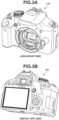
- Fig. 3 illustrates an example of a lens mount side and a display unit side of the imaging apparatus 100.
- the in-camera 130 is placed on the display unit side at a location where image data of the user can be acquired.
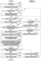
- a flowchart illustrating operations of the digital camera 100 will be described below with reference to Fig. 4 .
- the flowchart starts in a case where the power switch 125 is turned on.
- the system control unit 150 implements the flowchart by controlling the components of the digital camera 100. Unless otherwise specified, the system control unit 150 controls execution of each step of the flowchart described below.
- step S100 power is supplied to the components of the imaging apparatus 100, and the imaging apparatus 100 changes to a power-on state.
- step S101 the in-camera 130 is activated, and image data is acquired.
- step S102 the control unit 152 of the system control unit 150 performs person detection by setting a threshold for feature points of a person from the image data acquired in step S101 and determining whether matching feature points are greater than or equal to the preset threshold. In a case where a person is detected, the processing proceeds to step S103. On the other hand, in a case where no person is detected, step S102 is repeated.
- step S103 the control unit 152 of the system control unit 150 starts accumulating image data of the in-camera 130 in the accumulation area 141 of the system memory 123.
- step S104 the control unit 152 of the system control unit 150 performs detection by setting a threshold for feature points of a face of the person from the image data and determining whether matching feature points are greater than or equal to the preset threshold. In a case where the face of the person is detected, the processing proceeds to step S105. On the other hand, in a case where the face of the person is not detected, the processing proceeds to step S106.
- step S105 the control unit 152 of the system control unit 150 continues accumulating the image data of the in-camera 130 in the accumulation area 141 of the system memory 123.
- step S106 the control unit 152 of the system control unit 150 determines whether a predetermined time has passed since the detection of the person in step S102, using the system timer 122. In a case where the control unit 152 determines that the predetermined time has passed, the processing proceeds to step S107. On the other hand, in a case where the control unit 152 determines that the predetermined time has not passed, step S104 is repeated.
- step S107 signals accumulated in the accumulation area 141 of the system memory 123 are deleted.
- step S108 the control unit 152 of the system control unit 150 sets a threshold range and determines whether matching feature points of the face are greater than or equal to the preset threshold. In a case where the threshold is met or exceeded, the processing proceeds to step S109.
- step S110 the control unit 152 of the system control unit 150 determines whether a predetermined time has passed since the detection of the feature points of the face in step S108, using the system timer 122.
- step S 111 In a case where the control unit 152 determines that the predetermined time has passed, the processing proceeds to step S 111. On the other hand, in a case where the control unit 152 determines that the predetermined time has not passed, step S108 is repeated.
- step S109 the control unit 152 of the system control unit 150 finishes accumulating the image data of the in-camera 130 in the accumulation area 141 of the system memory 123.
- step S112 the determination unit 153 of the system control unit 150 acquires, as input data, signals accumulated in the accumulation area 141 of the system memory 123.
- step S113 the determination unit 153 of the system control unit 150 acquires, as model data, signals stored in the storage area 142 of the memory 140.
- step S114 the determination unit 153 of the system control unit 150 performs pattern matching on the input data and the model data and classifies the input data as data representing that the person is viewing through the EVF or data representing that the person is not viewing through the EVF, based on the rule base.
- step S115 the determination unit 153 of the system control unit 150 determines whether the input data is classified as data representing that the person is viewing through the EVF or data representing that the person is not viewing through the EVF, based on the result in step S114. In a case where the determination unit 153 determines that the input data is classified as data representing that the person is viewing through the EVF, the processing proceeds to step S116. On the other hand, in a case where the determination unit 153 determines that the input data is not classified as data representing an operation end, the processing proceeds to step S118.
- step S116 signals accumulated in the accumulation area 141 of the system memory 123 are deleted.
- step S117 the power control unit 160 controls the power unit 170 and the digital viewfinder portion 112 based on an EVF display mode instruction.
- step S118 signals accumulated in the accumulation area 141 of the system memory 123 are deleted.
- step S119 the display on the display unit 111 is maintained, and the processing returns to step S102.
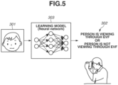
- FIG. 5 is a conceptual diagram illustrating an input/output configuration using a learning model according to the present exemplary embodiment.
- Input data 301 is input data.
- the input data 301 is collected by accumulating image data of the in-camera 130 in the accumulation area 141 of the system memory 123 in steps S103 to S109 in Fig. 4 .
- Output data 302 has two types, data representing that the person is viewing through the EVF and data representing that the person is not viewing through the EVF.
- a learning model is constructed using differences of combinations of changes in the image data of the in-camera 130 as feature points, and input data is classified.
- a learning model 303 is a learning model. Specific algorithms of machine learning are nearest neighbors methods, Naive Bayes methods, Decision Tree, and Support Vector Machine. Another specific algorithm is Deep Learning, which generates feature amounts and coupling weight coefficients for learning on its own using neural networks. Any of the above-described algorithms that can be used can be applied to the present exemplary embodiment as needed.
- Fig. 6 illustrates operations of a system to which the present invention using the configuration illustrated in Fig. 5 is applicable.
- Use of the learning model makes it possible to classify data as data representing that the person is viewing through the EVF or data representing that the person is not viewing through the EVF, making it possible to make a transition to the EVF display mode only in a case where data is data representing that the person is viewing through the EVF.
- Acquired image data of the in-camera 130 is transmitted to the calculation unit 151.
- a calculation result by the calculation unit 151 is transmitted to the control unit 152.
- the image data is transmitted to the accumulation area 141.
- the accumulated image data is transmitted as input data to the determination unit 153.
- a learning model is requested from the storage area 142.
- the learning model is transmitted from the storage area 142 to the determination unit 153.
- the determination unit 153 classifies, based on the learning model, the input data as data representing a face of a person or something else. In a case where the classification result by the determination unit 153 is a face of a person, an instruction to change to the EVF display mode is issued to the power control unit 160 and the control unit 152.
- the power control unit 160 controls the power unit 170
- the control unit 152 controls the digital viewfinder display unit 112, whereby a transition to the EVF display mode is made.
- the training unit 154 can include an error detection unit and an update unit.
- the error detection unit obtains an error between model data and output data output from an output layer of a neural network based on input data input to an input layer.
- the error detection unit can calculate an error between the output data from the neural network and the model data using a loss function.
- the update unit updates coupling weight coefficients between nodes of neural networks based on errors obtained by the error detection unit to reduce the errors.
- the update unit updates the coupling weight coefficients using, for example, a backpropagation method.
- the backpropagation method is a method for adjusting coupling weight coefficients between nodes of each neural network to reduce the above-described errors.
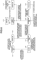
- step S400 the determination unit 153 of the system control unit 150 acquires signals accumulated in the accumulation area 141 of the system memory 123 as the input data 301.
- step S401 the determination unit 153 of the system control unit 150 acquires the learning model 303 stored in the storage area 142 of the memory 140.
- step S402 the determination unit 153 of the system control unit 150 inputs the input data 301 to the learning model 303 and classifies the input data 301 as data representing that the person is viewing through the EVF or data representing that the person is not viewing through the EVF.
- step S403 the determination unit 153 of the system control unit 150 determines whether the output data in step S402 is data representing that the person is viewing through the EVF. In a case where the determination unit 153 determines that the output data is classified as data representing that the person is viewing through the EVF, the processing proceeds to step S404. On the other hand, in a case where the determination unit 153 determines that the output data is not classified as data representing that the person is viewing through the EVF, the processing proceeds to step S406. In step S406, signals accumulated in the accumulation area 141 of the system memory 123 are deleted.
- step S404 the determination unit 153 of the system control unit 150 determines whether an operation is performed by the user based on signals from the operation unit 124. In a case where the determination unit 153 determines that an operation is performed, the processing proceeds to step S405. On the other hand, in a case where the determination unit 153 determines that no operation is performed, the processing proceeds to step S407.
- step S405 the training unit 154 of the system control unit 150 relearns the input data 301 as data representing that the person is viewing through the EVF and updates the learning model 303.
- step S406 signals accumulated in the accumulation area 141 of the system memory 123 are deleted.
- step S407 the determination unit 153 of the system control unit 150 determines whether a predetermined time has passed since the determination that the data is classified as data representing that the person is viewing through the EVF in step S403, using the system timer 122. In a case where the determination unit 153 determines that the predetermined time has passed, the processing proceeds to step S406. On the other hand, in a case where the determination unit 153 determines that the predetermined time has not passed, step S404 is repeated.
- step S406 signals accumulated in the accumulation area 141 of the system memory 123 are deleted.
- image data of the in-camera 130 at a time at which the user views through the EVF is classified as data representing that the person is viewing through the EVF or data representing that the person is not viewing through the EVF by performing pattern matching on the image data and the model data, and a transition to the EVF display mode is made only in a case where the image data is classified as data representing that the person is viewing through the EVF.
- the inclusion of the training unit 154 makes it possible to consider unique habits and behaviors of each user that are not applied to the pattern matching, and as the number of times of use increases, the classification accuracy improves, making it possible to make a transition to the EVF display mode without erroneous detection.
- the present invention is not limited to those described above.
- the present invention is applicable to any imaging apparatus capable of determining whether a person is viewing through the EVF, regardless of its form.
Landscapes
- Engineering & Computer Science (AREA)
- Signal Processing (AREA)
- Multimedia (AREA)
- Physics & Mathematics (AREA)
- Theoretical Computer Science (AREA)
- General Physics & Mathematics (AREA)
- Software Systems (AREA)
- Computing Systems (AREA)
- Artificial Intelligence (AREA)
- Evolutionary Computation (AREA)
- Data Mining & Analysis (AREA)
- General Engineering & Computer Science (AREA)
- Human Computer Interaction (AREA)
- Mathematical Physics (AREA)
- Medical Informatics (AREA)
- Computer Vision & Pattern Recognition (AREA)
- Computational Linguistics (AREA)
- Biomedical Technology (AREA)
- Life Sciences & Earth Sciences (AREA)
- Health & Medical Sciences (AREA)
- Biophysics (AREA)
- Molecular Biology (AREA)
- General Health & Medical Sciences (AREA)
- Studio Devices (AREA)
- Viewfinders (AREA)
- Cameras In General (AREA)
- Camera Bodies And Camera Details Or Accessories (AREA)
Abstract
Description
- The present invention relates to an imaging apparatus including an eyepiece portion.
- Imaging apparatuses that include an electronic viewfinder (EVF) have been known conventionally. In an imaging apparatus that includes an EVF, a proximity sensor is provided to determine whether a user is viewing through the EVF to detect an act of viewing through the EVF (eye proximity detection). The proximity sensor is a sensor for detecting the proximity of an object and does not guarantee that the user is actually viewing through the EVF. Thus, the sensor may erroneously detect eye proximity in a case where the user is hanging a strap of the camera around the neck or a camera is in contact with the body. Consequently, the EVF display continues, and power is consumed wastefully. Thus,
Japanese Patent Application Laid-Open No. 2013-225785 - PTL 1:
Japanese Patent Application Laid-Open No. 2013-225785 - With the conventional technology discussed in
Japanese Patent Application Laid-Open No. 2013-225785 - To achieve the above-described object, according to the present invention, an imaging apparatus includes a first imaging unit configured to image a subject, a second imaging unit arranged in a direction opposite to the first imaging unit, and an electronic viewfinder arranged in the same direction as the second imaging unit and configured to display an image captured by the first imaging unit, wherein the display on the electronic viewfinder is controlled based on image data captured by the second imaging unit. Advantageous Effects of Invention
- The present invention reduces wasteful power consumption by an electronic viewfinder (EVF).
-
- [
Fig. 1] Fig. 1 is a block diagram illustrating a configuration of an imaging apparatus according to a first exemplary embodiment of the present invention. - [
Fig. 2] Fig. 2 is a diagram illustrating functions of the imaging apparatus according to the first exemplary embodiment of the present invention. - [
Fig. 3] Fig. 3 is a diagram illustrating external views of a lens mount side and a display unit side of the imaging apparatus according to the first exemplary embodiment of the present invention. - [
Fig. 4] Fig. 4 is a flowchart illustrating operations of the imaging apparatus according to the first exemplary embodiment of the present invention. - [
Fig. 5] Fig. 5 is a conceptual diagram illustrating a configuration using a learning model of the imaging apparatus according to the first exemplary embodiment of the present invention. - [
Fig. 6] Fig. 6 is a diagram illustrating system operations according to the first exemplary embodiment of the present invention. - [
Fig. 7] Fig. 7 is a flowchart illustrating a learning phase of the imaging apparatus according to the first exemplary embodiment of the present invention. - Exemplary embodiments of the present invention will be described in detail below with reference to the attached drawings.
- It is to be noted that each exemplary embodiment described below is merely an example of implementation of the present invention and can be modified or changed as needed based on a configuration of an apparatus to which the present invention is applied or various conditions. Further, the exemplary embodiments can be combined as needed.
-
Fig. 1 is a block diagram illustrating a configuration of a camera with an interchangeable lens unit as an exemplary embodiment of the present invention. InFig. 1 , an imaging apparatus includes adigital camera body 100 and animaging lens 200. Theimaging lens 200 guides incident light to animage sensor 105. - First, a configuration of the
camera body 100 will be described below. - A
shutter control unit 104 controls ashutter 103 based on exposure information from animage processing unit 106 in coordination with alens control unit 204 configured to control astop 203. - An optical image of a subject (not illustrated) is formed on the
image sensor 105 through alens 205, thestop 203,lens mounts shutter 103, and theimage sensor 105 converts the optical image into an electric signal. - The
image processing unit 106 performs predetermined calculation processing on video signals input from theimage sensor 105, performs image processing such as pixel interpolation processing, color conversion processing, and white balance processing on the video signals based on the calculation result, and outputs the resulting video signals to adisplay unit 111. Further, the resulting video signals are output to adigital viewfinder portion 112 in a case where eye proximity is detected based on images acquired by an in-camera 130. Further, theimage processing unit 106 has a function of compressing images such as Joint Photographic Experts Group (JPEG) images. Thedisplay unit 111 is a display having a display area larger than thedigital viewfinder portion 112. - A
recording medium 107 is a removable memory such as a semiconductor memory for recording or reading image data. - A
communication unit 121 is connected wirelessly or via a wired cable and transmits and receives video signals and audio signals. Thecommunication unit 121 can be connected to a wireless local area network (wireless LAN) and the Internet. Thecommunication unit 121 can transmit captured images (including through images) and images recorded in arecording circuit 107 and can receive image data and various types of other information from external devices. - An
operation unit 124 is an operation unit that inputs various predetermined operation instructions to asystem control unit 150. The operation unit is composed of one of a switch, a dial, a touch panel, pointing using line-of-sight detection, and a voice recognition apparatus or a combination thereof. - A
system timer 122 measures a time for use in various controls and the time of a built-in clock. - A
system memory 123 uses a random access memory (RAM). Constant numbers and variable numbers for operations of thesystem control unit 150 and programs read from amemory 140 are loaded into thesystem memory 123. Further, thesystem memory 123 also has a function of accumulating image data acquired by the in-camera 130. - A
power switch 125 is used to switch and set a power-on mode and a power-off mode of animaging apparatus 100. - A
shutter button 126 is an operation unit for issuing imaging instructions. - A
first shutter switch 127 is turned on in a case where theshutter button 126 of theimaging apparatus 100 is partially operated, i.e., half-pressed (imaging preparation instruction), and a first shutter switch signal SW1 is generated. The first shutter switch signal SW1 causes operations such as auto-focus processing, automatic exposure processing, auto white balance processing, and preliminary flash emission processing to be started. - A
second shutter switch 128 is turned on in a case where theshutter button 126 is completely operated, i.e., fully-pressed (imaging instruction), and a second shutter switch signal SW2 is generated. - The
system control unit 150 starts performing operations of an imaging process from the reading of a signal from theimage sensor 105 to the writing of image data to therecording circuit 107 based on the second shutter switch signal SW2. - The in-
camera 130 is a camera arranged to image a direction opposite to theimage sensor 105. - The
memory 140 is an electrically erasable and recordable non-volatile memory. For example, a read-only memory (ROM) is used. Constant numbers and programs for operations of thesystem control unit 150 are stored. The programs here refer to programs for performing various flowcharts described below according to the present exemplary embodiment. - The
system control unit 150 is a control unit including at least one processor and controls operations of theentire imaging apparatus 100. - A
power control unit 160 includes a battery detection circuit, a protection circuit, a direct-current (DC) to DC converter, and a Low Drop-Out (LDO) regulator. Thepower control unit 160 has a function of protecting a load circuit connected to a power circuit by deactivating a power source in a case where installation or uninstallation of a battery, a battery type, a battery level, or an overcurrent is detected. Thepower control unit 160 controls apower unit 170 based on instructions from the system control unit and supplies a specific power voltage to each component of theimaging apparatus 100 for a specific period. - The
power unit 170 includes a primary battery such as an alkaline battery or a lithium battery, a secondary battery such as a nickel cadmium (NiCd) battery, a nickel-metal hydride (NiMH) battery, or a lithium ion (Li) battery, and an alternating current (AC) adapter. - The lens mounts 102 and 202 are interfaces for connecting the
imaging apparatus 100 to alens unit 200.Connectors imaging apparatus 100 to thelens unit 200 and are controlled by thesystem control unit 150. - The
lens unit 200 is an interchangeable-lens type lens unit and guides an optical image of a subject (not illustrated) from thelens 205 through thestop 203, thelens mount shutter 103 and forms the optical image on theimage sensor 105. - Next, a configuration of the
lens unit 200 will be described below. - The
lens control unit 204 controls theentire lens unit 200. Thelens control unit 204 has a function of a memory for storing constant numbers, variable numbers, and programs for operations and a function of a non-volatile memory for storing identification information such as a number specific to thelens unit 200, management information, function information such as an aperture stop value, a minimum stop value, and a focal length, and current and previous setting values. Thelens control unit 204 is capable of performing auto-focus (AF) operations by controlling focusing of thelens 205 based on a focused state of an image measured by theimage processing unit 106 and changing a position where the subject image having entered theimage sensor 105 is formed. Further, thelens control unit 204 also has a function of controlling thestop 203 and a function of controlling zooming of thelens 205. - Next, functions of a
digital camera 100 will be described below with reference toFig. 2 . - An
accumulation area 141 of thesystem memory 123 is composed of a finite buffer. Astorage area 142 of thememory 140 stores image data and a rule base associated with the image data. Adetermination unit 153 refers to the image data and the rule base in performing pattern matching on signals. Acalculation unit 151 of thesystem control unit 150 outputs image data output from the in-camera 130 to acontrol unit 152 of thesystem control unit 150. - The
control unit 152 of thesystem control unit 150 performs control to accumulate image data output from the in-camera 130 in theaccumulation area 141 of thesystem memory 123 from thecalculation unit 151. - Further, in a case where the
determination unit 153 determines that eye proximity is detected, thedigital viewfinder portion 112 is controlled, and outputting to thedigital viewfinder portion 112 is performed. Thedetermination unit 153 of thesystem control unit 150 performs pattern matching on a signal accumulated in theaccumulation area 141 and image data stored in thestorage area 142. Further, thedetermination unit 153 classifies image data accumulated in theaccumulation area 141 as data representing that a user is viewing through the EVF or data representing that a user is not viewing through the EVF based on the rule base. - In a case where data is classified as data representing that a user is viewing through the EVF, a signal for making a transition to an EVF display mode is output to the
power control unit 160 and thecontrol unit 152. - The
power control unit 160 and thecontrol unit 152 make a transition to the EVF display mode based on the determination result from thedetermination unit 153. - A
training unit 154 performs learning using image data stored in thestorage area 142 as input and a flag indicating whether the corresponding user is viewing through the EVF or is not viewing through the EVF as training data. A trained model having finished the learning becomes an inference model that uses image data from the in-camera as input and outputs an inference that the user is viewing through the EVF or is not viewing through the EVF. - Next, a location where the in-
camera 130 is placed will be described below with reference toFig. 3. Fig. 3 illustrates an example of a lens mount side and a display unit side of theimaging apparatus 100. The in-camera 130 is placed on the display unit side at a location where image data of the user can be acquired. - A flowchart illustrating operations of the
digital camera 100 will be described below with reference toFig. 4 . The flowchart starts in a case where thepower switch 125 is turned on. Further, thesystem control unit 150 implements the flowchart by controlling the components of thedigital camera 100. Unless otherwise specified, thesystem control unit 150 controls execution of each step of the flowchart described below. - In step S100, power is supplied to the components of the
imaging apparatus 100, and theimaging apparatus 100 changes to a power-on state. - In step S101, the in-
camera 130 is activated, and image data is acquired. - In step S102, the
control unit 152 of thesystem control unit 150 performs person detection by setting a threshold for feature points of a person from the image data acquired in step S101 and determining whether matching feature points are greater than or equal to the preset threshold. In a case where a person is detected, the processing proceeds to step S103. On the other hand, in a case where no person is detected, step S102 is repeated. - In step S103, the
control unit 152 of thesystem control unit 150 starts accumulating image data of the in-camera 130 in theaccumulation area 141 of thesystem memory 123. - In step S104, the
control unit 152 of thesystem control unit 150 performs detection by setting a threshold for feature points of a face of the person from the image data and determining whether matching feature points are greater than or equal to the preset threshold. In a case where the face of the person is detected, the processing proceeds to step S105. On the other hand, in a case where the face of the person is not detected, the processing proceeds to step S106. - In step S105, the
control unit 152 of thesystem control unit 150 continues accumulating the image data of the in-camera 130 in theaccumulation area 141 of thesystem memory 123. - In step S106, the
control unit 152 of thesystem control unit 150 determines whether a predetermined time has passed since the detection of the person in step S102, using thesystem timer 122. In a case where thecontrol unit 152 determines that the predetermined time has passed, the processing proceeds to step S107. On the other hand, in a case where thecontrol unit 152 determines that the predetermined time has not passed, step S104 is repeated. - In step S107, signals accumulated in the
accumulation area 141 of thesystem memory 123 are deleted. - In step S108, the
control unit 152 of thesystem control unit 150 sets a threshold range and determines whether matching feature points of the face are greater than or equal to the preset threshold. In a case where the threshold is met or exceeded, the processing proceeds to step S109. - In step S110, the
control unit 152 of thesystem control unit 150 determines whether a predetermined time has passed since the detection of the feature points of the face in step S108, using thesystem timer 122. - In a case where the
control unit 152 determines that the predetermined time has passed, the processing proceeds to stepS 111. On the other hand, in a case where thecontrol unit 152 determines that the predetermined time has not passed, step S108 is repeated. - In step S109, the
control unit 152 of thesystem control unit 150 finishes accumulating the image data of the in-camera 130 in theaccumulation area 141 of thesystem memory 123. - In step S112, the
determination unit 153 of thesystem control unit 150 acquires, as input data, signals accumulated in theaccumulation area 141 of thesystem memory 123. - In step S113, the
determination unit 153 of thesystem control unit 150 acquires, as model data, signals stored in thestorage area 142 of thememory 140. - In step S114, the
determination unit 153 of thesystem control unit 150 performs pattern matching on the input data and the model data and classifies the input data as data representing that the person is viewing through the EVF or data representing that the person is not viewing through the EVF, based on the rule base. - In step S115, the
determination unit 153 of thesystem control unit 150 determines whether the input data is classified as data representing that the person is viewing through the EVF or data representing that the person is not viewing through the EVF, based on the result in step S114. In a case where thedetermination unit 153 determines that the input data is classified as data representing that the person is viewing through the EVF, the processing proceeds to step S116. On the other hand, in a case where thedetermination unit 153 determines that the input data is not classified as data representing an operation end, the processing proceeds to step S118. - In step S116, signals accumulated in the
accumulation area 141 of thesystem memory 123 are deleted. - In step S117, the
power control unit 160 controls thepower unit 170 and thedigital viewfinder portion 112 based on an EVF display mode instruction. - In step S118, signals accumulated in the
accumulation area 141 of thesystem memory 123 are deleted. - In step S119, the display on the
display unit 111 is maintained, and the processing returns to step S102. - Next, a technique for appropriate EVF display by determining whether the user is viewing through the EVF using a learning model in a case where the person is detected will be described below.
Fig. 5 is a conceptual diagram illustrating an input/output configuration using a learning model according to the present exemplary embodiment.Input data 301 is input data. Theinput data 301 is collected by accumulating image data of the in-camera 130 in theaccumulation area 141 of thesystem memory 123 in steps S103 to S109 inFig. 4 . -
Output data 302 has two types, data representing that the person is viewing through the EVF and data representing that the person is not viewing through the EVF. A learning model is constructed using differences of combinations of changes in the image data of the in-camera 130 as feature points, and input data is classified. - A
learning model 303 is a learning model. Specific algorithms of machine learning are nearest neighbors methods, Naive Bayes methods, Decision Tree, and Support Vector Machine. Another specific algorithm is Deep Learning, which generates feature amounts and coupling weight coefficients for learning on its own using neural networks. Any of the above-described algorithms that can be used can be applied to the present exemplary embodiment as needed. -
Fig. 6 illustrates operations of a system to which the present invention using the configuration illustrated inFig. 5 is applicable. Use of the learning model makes it possible to classify data as data representing that the person is viewing through the EVF or data representing that the person is not viewing through the EVF, making it possible to make a transition to the EVF display mode only in a case where data is data representing that the person is viewing through the EVF. - Acquired image data of the in-
camera 130 is transmitted to thecalculation unit 151. A calculation result by thecalculation unit 151 is transmitted to thecontrol unit 152. In a case where thecontrol unit 152 starts accumulation, the image data is transmitted to theaccumulation area 141. The accumulated image data is transmitted as input data to thedetermination unit 153. A learning model is requested from thestorage area 142. - The learning model is transmitted from the
storage area 142 to thedetermination unit 153. Thedetermination unit 153 classifies, based on the learning model, the input data as data representing a face of a person or something else. In a case where the classification result by thedetermination unit 153 is a face of a person, an instruction to change to the EVF display mode is issued to thepower control unit 160 and thecontrol unit 152. Thepower control unit 160 controls thepower unit 170, and thecontrol unit 152 controls the digitalviewfinder display unit 112, whereby a transition to the EVF display mode is made. - Further, the
training unit 154 can include an error detection unit and an update unit. The error detection unit obtains an error between model data and output data output from an output layer of a neural network based on input data input to an input layer. The error detection unit can calculate an error between the output data from the neural network and the model data using a loss function. - The update unit updates coupling weight coefficients between nodes of neural networks based on errors obtained by the error detection unit to reduce the errors. The update unit updates the coupling weight coefficients using, for example, a backpropagation method. The backpropagation method is a method for adjusting coupling weight coefficients between nodes of each neural network to reduce the above-described errors.
- A flowchart will be described below with reference to
Fig. 7 in which after data is classified as data representing that the person is viewing through the EVF or data representing that the person is not viewing through the EVF, error detection is performed based on whether a predetermined imaging operation is performed by the user within a predetermined time, and the learning model is updated by relearning in a case where an error occurs. - In step S400, the
determination unit 153 of thesystem control unit 150 acquires signals accumulated in theaccumulation area 141 of thesystem memory 123 as theinput data 301. - In step S401, the
determination unit 153 of thesystem control unit 150 acquires thelearning model 303 stored in thestorage area 142 of thememory 140. - In step S402, the
determination unit 153 of thesystem control unit 150 inputs theinput data 301 to thelearning model 303 and classifies theinput data 301 as data representing that the person is viewing through the EVF or data representing that the person is not viewing through the EVF. - In step S403, the
determination unit 153 of thesystem control unit 150 determines whether the output data in step S402 is data representing that the person is viewing through the EVF. In a case where thedetermination unit 153 determines that the output data is classified as data representing that the person is viewing through the EVF, the processing proceeds to step S404. On the other hand, in a case where thedetermination unit 153 determines that the output data is not classified as data representing that the person is viewing through the EVF, the processing proceeds to step S406. In step S406, signals accumulated in theaccumulation area 141 of thesystem memory 123 are deleted. - In step S404, the
determination unit 153 of thesystem control unit 150 determines whether an operation is performed by the user based on signals from theoperation unit 124. In a case where thedetermination unit 153 determines that an operation is performed, the processing proceeds to step S405. On the other hand, in a case where thedetermination unit 153 determines that no operation is performed, the processing proceeds to step S407. - In step S405, the
training unit 154 of thesystem control unit 150 relearns theinput data 301 as data representing that the person is viewing through the EVF and updates thelearning model 303. - In step S406, signals accumulated in the
accumulation area 141 of thesystem memory 123 are deleted. - In step S407, the
determination unit 153 of thesystem control unit 150 determines whether a predetermined time has passed since the determination that the data is classified as data representing that the person is viewing through the EVF in step S403, using thesystem timer 122. In a case where thedetermination unit 153 determines that the predetermined time has passed, the processing proceeds to step S406. On the other hand, in a case where thedetermination unit 153 determines that the predetermined time has not passed, step S404 is repeated. - In step S406, signals accumulated in the
accumulation area 141 of thesystem memory 123 are deleted. - As described above, image data of the in-
camera 130 at a time at which the user views through the EVF is classified as data representing that the person is viewing through the EVF or data representing that the person is not viewing through the EVF by performing pattern matching on the image data and the model data, and a transition to the EVF display mode is made only in a case where the image data is classified as data representing that the person is viewing through the EVF. - Furthermore, the inclusion of the
training unit 154 makes it possible to consider unique habits and behaviors of each user that are not applied to the pattern matching, and as the number of times of use increases, the classification accuracy improves, making it possible to make a transition to the EVF display mode without erroneous detection. - While the imaging apparatuses are described as an example according to the present exemplary embodiment, the present invention is not limited to those described above. The present invention is applicable to any imaging apparatus capable of determining whether a person is viewing through the EVF, regardless of its form.
- While exemplary embodiments of the present invention have been described above, the present invention is not limited to the exemplary embodiments, and various modifications and changes can be made within the spirit of the present invention.
- The present invention is not limited to the above embodiments and various changes and modifications can be made within the spirit and scope of the present invention. Therefore, to apprise the public of the scope of the present invention, the following claims are made.
- This application claims priority from
Japanese Patent Application No. 2021-104983 filed June 24, 2021
Claims (10)
- An imaging apparatus comprising:a first imaging unit configured to image a subject;a second imaging unit arranged in a direction opposite to the first imaging unit; andan electronic viewfinder arranged in the same direction as the second imaging unit and configured to display an image captured by the first imaging unit,wherein the display on the electronic viewfinder is controlled based on image data captured by the second imaging unit.
- The imaging apparatus according to Claim 1, further comprising a determination unit configured to determine, based on the image data captured by the second imaging unit, whether a user is attempting to view through the electronic viewfinder,wherein in a case where the determination unit does not determine that the user is attempting to view through the electronic viewfinder, the electronic viewfinder does not display the image captured by the first imaging unit, andwherein in a case where the determination unit determines that the user is attempting to view through the electronic viewfinder, the electronic viewfinder displays the image captured by the first imaging unit.
- The imaging apparatus according to Claim 2, further comprising a display unit having a display area larger than the electronic viewfinder,wherein in a case where the determination unit does not determine that the user is attempting to view through the electronic viewfinder, the display unit displays the image captured by the first imaging unit, andwherein in a case where the determination unit determines that the user is attempting to view through the electronic viewfinder, the display unit does not display the image captured by the first imaging unit.
- The imaging apparatus according to Claim 2, wherein the determination unit uses a trained model in determining whether the user is attempting to view through the electronic viewfinder.
- The imaging apparatus according to Claim 4, wherein in a case where processing for imaging using the first imaging unit and recording image data is performed before a predetermined time passes after the determination unit determines that the user is attempting to view through the electronic viewfinder, the trained model is relearned using, as input data, image data used by the determination unit in determining that the user is attempting to view through the electronic viewfinder and, as training data, information indicating that the user is attempting to view through the electronic viewfinder.
- A method for controlling an imaging apparatus including a first imaging unit configured to image a subject, a second imaging unit arranged in a direction opposite to the first imaging unit, and an electronic viewfinder arranged in the same direction as the second imaging unit and configured to display an image captured by the first imaging unit,
wherein the display on the electronic viewfinder is controlled based on image data captured by the second imaging unit. - The method for controlling the imaging apparatus according to Claim 6, further comprising determining, based on the image data captured by the second imaging unit, whether a user is attempting to view through the electronic viewfinder,wherein in a case where the determining does not determine that the user is attempting to view through the electronic viewfinder, the image captured by the first imaging unit is not displayed on the electronic viewfinder, andwherein in a case where the determining determines that the user is attempting to view through the electronic viewfinder, control is performed to display the image captured by the first imaging unit on the electronic viewfinder.
- The method for controlling the imaging apparatus according to Claim 7,wherein the imaging apparatus further includes a display unit having a display area larger than the electronic viewfinder,wherein in a case where the determining does not determine that the user is attempting to view through the electronic viewfinder, the image captured by the first imaging unit is displayed on the display unit, andwherein in a case where the determining determines that the user is attempting to view through the electronic viewfinder, the image captured by the first imaging unit is not displayed on the display unit.
- The method for controlling the imaging apparatus according to Claim 7, wherein the determining uses a trained model in determining whether the user is attempting to view through the electronic viewfinder.
- The method for controlling the imaging apparatus according to Claim 9, wherein in a case where processing for imaging using the first imaging unit and recording image data is performed before a predetermined time passes after the determining determines that the user is attempting to view through the electronic viewfinder, the trained model is relearned using, as input data, image data used in determining that the user is attempting to view through the electronic viewfinder and, as training data, information indicating that the user is attempting to view through the electronic viewfinder.
Applications Claiming Priority (2)
| Application Number | Priority Date | Filing Date | Title |
|---|---|---|---|
| JP2021104983A JP7790879B2 (en) | 2021-06-24 | 2021-06-24 | Image capture device, image capture device control method, and program |
| PCT/JP2022/024250 WO2022270420A1 (en) | 2021-06-24 | 2022-06-17 | Imaging device having eyepiece section, method for controlling imaging device, and recording medium |
Publications (2)
| Publication Number | Publication Date |
|---|---|
| EP4362449A1 true EP4362449A1 (en) | 2024-05-01 |
| EP4362449A4 EP4362449A4 (en) | 2025-06-11 |
Family
ID=84544888
Family Applications (1)
| Application Number | Title | Priority Date | Filing Date |
|---|---|---|---|
| EP22828337.0A Pending EP4362449A4 (en) | 2021-06-24 | 2022-06-17 | EYE SECTION IMAGING DEVICE, DRIVING METHOD THEREOF, AND RECORDING MEDIUM |
Country Status (6)
| Country | Link |
|---|---|
| US (1) | US20240129618A1 (en) |
| EP (1) | EP4362449A4 (en) |
| JP (1) | JP7790879B2 (en) |
| KR (1) | KR20240001190A (en) |
| CN (1) | CN117561718A (en) |
| WO (1) | WO2022270420A1 (en) |
Family Cites Families (10)
| Publication number | Priority date | Publication date | Assignee | Title |
|---|---|---|---|---|
| JPH09325260A (en) * | 1996-06-06 | 1997-12-16 | Canon Inc | Imaging device with eyepiece detection function |
| JP3530679B2 (en) * | 1996-06-14 | 2004-05-24 | キヤノン株式会社 | Imaging device with eyepiece detection function |
| JP2013225785A (en) | 2012-04-23 | 2013-10-31 | Seiko Epson Corp | Electronic apparatus and electronic apparatus body |
| JP2018189859A (en) * | 2017-05-10 | 2018-11-29 | キヤノン株式会社 | Imaging device |
| JP6889625B2 (en) * | 2017-06-29 | 2021-06-18 | キヤノン株式会社 | Electronic devices equipped with display devices and their control methods, programs and storage media |
| JP7433788B2 (en) * | 2019-07-03 | 2024-02-20 | キヤノン株式会社 | Control device, imaging device, control method, program |
| JP7253988B2 (en) * | 2019-07-03 | 2023-04-07 | キヤノン株式会社 | DISPLAY CONTROL DEVICE AND CONTROL METHOD THEREOF, DISPLAY CONTROL SYSTEM AND PROGRAM |
| US11343412B2 (en) * | 2019-10-22 | 2022-05-24 | Intel Corporation | User detection and user attention detection using multi-zone depth sensing |
| JP7377078B2 (en) * | 2019-11-21 | 2023-11-09 | キヤノン株式会社 | Image processing device, image processing method, and imaging device |
| JP7419057B2 (en) | 2019-12-27 | 2024-01-22 | ライオン株式会社 | Tablets and coated tablets |
-
2021
- 2021-06-24 JP JP2021104983A patent/JP7790879B2/en active Active
-
2022
- 2022-06-17 EP EP22828337.0A patent/EP4362449A4/en active Pending
- 2022-06-17 KR KR1020237040368A patent/KR20240001190A/en active Pending
- 2022-06-17 WO PCT/JP2022/024250 patent/WO2022270420A1/en not_active Ceased
- 2022-06-17 CN CN202280044042.8A patent/CN117561718A/en active Pending
-
2023
- 2023-12-21 US US18/393,342 patent/US20240129618A1/en active Pending
Also Published As
| Publication number | Publication date |
|---|---|
| US20240129618A1 (en) | 2024-04-18 |
| CN117561718A (en) | 2024-02-13 |
| KR20240001190A (en) | 2024-01-03 |
| WO2022270420A1 (en) | 2022-12-29 |
| JP7790879B2 (en) | 2025-12-23 |
| JP2023003729A (en) | 2023-01-17 |
| EP4362449A4 (en) | 2025-06-11 |
Similar Documents
| Publication | Publication Date | Title |
|---|---|---|
| EP2146242B1 (en) | Image pickup device and image pickup method | |
| EP2924976B1 (en) | Image pickup apparatus, electronic device, and control method | |
| EP1878219B1 (en) | Image capturing apparatus and its control method | |
| JP2005184508A (en) | Imaging apparatus and control method thereof | |
| CN113286075A (en) | Image processing apparatus, image capturing apparatus, image processing method, and storage medium | |
| EP3761628B1 (en) | Display control apparatus for an electronic viewfinder in a camera and control method thereof | |
| EP4362449A1 (en) | Imaging device having eyepiece section, method for controlling imaging device, and recording medium | |
| JP5917040B2 (en) | Image processing apparatus and image processing method | |
| JP2008299430A (en) | Image processing apparatus, image processing method, and image processing program | |
| JP5841394B2 (en) | Imaging apparatus and control method thereof | |
| US20220319148A1 (en) | Image processing apparatus and method for controlling the same | |
| JP2008300986A (en) | Image processing apparatus, image processing method, and image processing program | |
| JP2005292740A (en) | Electronic camera | |
| US11317023B2 (en) | Terminal apparatus that saves power by detecting user operation, power supply control method therefor, and storage medium | |
| US20240397017A1 (en) | Image pickup apparatus that reduces loss of opportunities for photographing, control method for image pickup apparatus, and storage medium | |
| JP5697718B2 (en) | Electronics | |
| JP4750616B2 (en) | Imaging apparatus and control method thereof | |
| JP5004739B2 (en) | Imaging apparatus and control method | |
| JP6324004B2 (en) | Imaging apparatus and control method thereof | |
| KR100894485B1 (en) | Imaging Device and Control Method | |
| CN110022432B (en) | Lens control apparatus and control method for tracking moving object | |
| JP2005197885A (en) | Imaging apparatus and control method thereof | |
| JP2012213173A (en) | Imaging apparatus and control method | |
| JP2018085666A (en) | Imaging device | |
| JP2016032250A (en) | OPTICAL DEVICE, OPTICAL DEVICE SYSTEM, AND OPTICAL DEVICE CONTROL METHOD |
Legal Events
| Date | Code | Title | Description |
|---|---|---|---|
| STAA | Information on the status of an ep patent application or granted ep patent |
Free format text: STATUS: THE INTERNATIONAL PUBLICATION HAS BEEN MADE |
|
| PUAI | Public reference made under article 153(3) epc to a published international application that has entered the european phase |
Free format text: ORIGINAL CODE: 0009012 |
|
| STAA | Information on the status of an ep patent application or granted ep patent |
Free format text: STATUS: REQUEST FOR EXAMINATION WAS MADE |
|
| 17P | Request for examination filed |
Effective date: 20240124 |
|
| AK | Designated contracting states |
Kind code of ref document: A1 Designated state(s): AL AT BE BG CH CY CZ DE DK EE ES FI FR GB GR HR HU IE IS IT LI LT LU LV MC MK MT NL NO PL PT RO RS SE SI SK SM TR |
|
| DAV | Request for validation of the european patent (deleted) | ||
| DAX | Request for extension of the european patent (deleted) | ||
| REG | Reference to a national code |
Ref country code: DE Ref legal event code: R079 Free format text: PREVIOUS MAIN CLASS: H04N0005232000 Ipc: H04N0023600000 |
|
| A4 | Supplementary search report drawn up and despatched |
Effective date: 20250509 |
|
| RIC1 | Information provided on ipc code assigned before grant |
Ipc: H04N 23/65 20230101ALI20250502BHEP Ipc: G03B 17/02 20210101ALI20250502BHEP Ipc: G03B 13/02 20210101ALI20250502BHEP Ipc: H04N 23/60 20230101AFI20250502BHEP |