EP4362145A1 - Redox flow battery system - Google Patents
Redox flow battery system Download PDFInfo
- Publication number
- EP4362145A1 EP4362145A1 EP22828026.9A EP22828026A EP4362145A1 EP 4362145 A1 EP4362145 A1 EP 4362145A1 EP 22828026 A EP22828026 A EP 22828026A EP 4362145 A1 EP4362145 A1 EP 4362145A1
- Authority
- EP
- European Patent Office
- Prior art keywords
- banks
- soc
- bank
- state
- charge
- Prior art date
- Legal status (The legal status is an assumption and is not a legal conclusion. Google has not performed a legal analysis and makes no representation as to the accuracy of the status listed.)
- Pending
Links
Images
Classifications
-
- H—ELECTRICITY
- H01—ELECTRIC ELEMENTS
- H01M—PROCESSES OR MEANS, e.g. BATTERIES, FOR THE DIRECT CONVERSION OF CHEMICAL ENERGY INTO ELECTRICAL ENERGY
- H01M8/00—Fuel cells; Manufacture thereof
- H01M8/18—Regenerative fuel cells, e.g. redox flow batteries or secondary fuel cells
-
- H—ELECTRICITY
- H01—ELECTRIC ELEMENTS
- H01M—PROCESSES OR MEANS, e.g. BATTERIES, FOR THE DIRECT CONVERSION OF CHEMICAL ENERGY INTO ELECTRICAL ENERGY
- H01M8/00—Fuel cells; Manufacture thereof
- H01M8/04—Auxiliary arrangements, e.g. for control of pressure or for circulation of fluids
- H01M8/04298—Processes for controlling fuel cells or fuel cell systems
- H01M8/04694—Processes for controlling fuel cells or fuel cell systems characterised by variables to be controlled
- H01M8/04858—Electric variables
- H01M8/04925—Power, energy, capacity or load
- H01M8/04932—Power, energy, capacity or load of the individual fuel cell
-
- H—ELECTRICITY
- H01—ELECTRIC ELEMENTS
- H01M—PROCESSES OR MEANS, e.g. BATTERIES, FOR THE DIRECT CONVERSION OF CHEMICAL ENERGY INTO ELECTRICAL ENERGY
- H01M8/00—Fuel cells; Manufacture thereof
- H01M8/04—Auxiliary arrangements, e.g. for control of pressure or for circulation of fluids
- H01M8/04082—Arrangements for control of reactant parameters, e.g. pressure or concentration
- H01M8/04186—Arrangements for control of reactant parameters, e.g. pressure or concentration of liquid-charged or electrolyte-charged reactants
-
- H—ELECTRICITY
- H01—ELECTRIC ELEMENTS
- H01M—PROCESSES OR MEANS, e.g. BATTERIES, FOR THE DIRECT CONVERSION OF CHEMICAL ENERGY INTO ELECTRICAL ENERGY
- H01M8/00—Fuel cells; Manufacture thereof
- H01M8/04—Auxiliary arrangements, e.g. for control of pressure or for circulation of fluids
- H01M8/04298—Processes for controlling fuel cells or fuel cell systems
- H01M8/04694—Processes for controlling fuel cells or fuel cell systems characterised by variables to be controlled
- H01M8/04858—Electric variables
-
- H—ELECTRICITY
- H01—ELECTRIC ELEMENTS
- H01M—PROCESSES OR MEANS, e.g. BATTERIES, FOR THE DIRECT CONVERSION OF CHEMICAL ENERGY INTO ELECTRICAL ENERGY
- H01M8/00—Fuel cells; Manufacture thereof
- H01M8/18—Regenerative fuel cells, e.g. redox flow batteries or secondary fuel cells
- H01M8/184—Regeneration by electrochemical means
- H01M8/188—Regeneration by electrochemical means by recharging of redox couples containing fluids; Redox flow type batteries
-
- H—ELECTRICITY
- H01—ELECTRIC ELEMENTS
- H01M—PROCESSES OR MEANS, e.g. BATTERIES, FOR THE DIRECT CONVERSION OF CHEMICAL ENERGY INTO ELECTRICAL ENERGY
- H01M8/00—Fuel cells; Manufacture thereof
- H01M8/24—Grouping of fuel cells, e.g. stacking of fuel cells
- H01M8/249—Grouping of fuel cells, e.g. stacking of fuel cells comprising two or more groupings of fuel cells, e.g. modular assemblies
-
- Y—GENERAL TAGGING OF NEW TECHNOLOGICAL DEVELOPMENTS; GENERAL TAGGING OF CROSS-SECTIONAL TECHNOLOGIES SPANNING OVER SEVERAL SECTIONS OF THE IPC; TECHNICAL SUBJECTS COVERED BY FORMER USPC CROSS-REFERENCE ART COLLECTIONS [XRACs] AND DIGESTS
- Y02—TECHNOLOGIES OR APPLICATIONS FOR MITIGATION OR ADAPTATION AGAINST CLIMATE CHANGE
- Y02E—REDUCTION OF GREENHOUSE GAS [GHG] EMISSIONS, RELATED TO ENERGY GENERATION, TRANSMISSION OR DISTRIBUTION
- Y02E60/00—Enabling technologies; Technologies with a potential or indirect contribution to GHG emissions mitigation
- Y02E60/30—Hydrogen technology
- Y02E60/50—Fuel cells
Definitions
- the present disclosure relates to a redox flow battery system.
- PTL 1 discloses an operation method of a redox flow battery system that performs charging and discharging by supplying a positive electrolyte and a negative electrolyte to a battery cell.
- PTL 1 it is described that a variation in voltage between a plurality of banks is controlled in the redox flow battery system including the banks.
- a redox flow battery system of the present disclosure includes: a plurality of banks; a power conversion device provided in each of the plurality of banks; and a controller that controls a state of charge of each of the plurality of banks by controlling the power conversion device.
- each of the plurality of banks includes a battery cell that performs charging and discharging by the supply of an electrolytic solution
- the plurality of banks include: a plurality of first banks controlled to be in a first state of charge; and one or more second banks excluding the first banks, and the controller controls a state of charge of the second bank to be a second state of charge different from the first state of charge.
- the usage range of the state of charge (SOC) is limited to suppress the decrease in the battery performance due to a side reaction.
- the technique described in PTL 1 causes the SOCs of the banks to be as equal as possible by performing voltage control that reduces the difference in voltage between the banks.
- operation is performed so as to cause the SOCs of all of the banks to be equal within an SOC range in which a side reaction does not occur. Therefore, the usage range of the SOC cannot be expanded.
- An object of the present disclosure is to provide a redox flow battery system capable of improving the decrease in battery performance due to a side reaction while being able to realize high energy density.
- the redox flow battery system of the present disclosure is capable of improving the decrease in the battery performance due to the side reaction while being able to realize high energy density.
- the inventors of the present invention have gained the following insight as a result of intensive research regarding acquisition of high energy density in a redox flow battery and the influence of the acquisition of the high energy density on the battery performance.
- One measure to enhance the energy density of the redox flow battery is to expand the usage range of the SOC.
- a side reaction may occur, and the battery performance may be adversely affected.
- the SOC is managed to be maintained within a certain range in order to suppress the decrease in the battery performance due to a side reaction.
- an active material ion included in the electrolytic solution may be deposited by the side reaction.
- the active material ion may not function as an active material.
- the deposition of the active material ion causes the deterioration of the electrolytic solution and the decrease in the battery capacity.
- a deposit of the active material ion causes the deterioration of a battery cell by adhering to an electrode constituting the battery cell, for example.
- the inventors of the present invention have found that it may be possible to dissolute a product generated by a side reaction into the electrolytic solution as an ion again by a reversible reaction.
- a deposit of an active material ion is generated by a side reaction in the region in which the SOC is high, it may be possible to cause the deposit to return into an ion again in the region in which the SOC is low.
- a deposit of an active material ion is generated by a side reaction in the region in which the SOC is low, it may be possible to cause the deposit to return into an ion again in the region in which the SOC is high.
- the control of the SOC described above needs to be performed when the battery cell is not performing charging and discharging.
- the control of the SOC described above is executed, the operation of the redox flow battery is stopped, and hence a restriction occurs in the operation. There is less freedom of operation for a user.
- the inventors of the present invention propose shifting the SOCs between the plurality of banks in the redox flow battery system including the banks in order to realize high energy density.
- control is not performed so as to cause the SOCs of all of the banks to be equal, and control is performed such that the SOCs of some banks are different.
- the redox flow battery system of the present disclosure is capable of improving the decrease in the battery characteristics due to the side reaction while being able to realize high energy density.
- the state of charge of the bank means the state of charge of a battery cell constituting the bank. When there are a plurality of battery cells, the state of charge of the battery cell is an average value of the states of charge of the plurality of battery cells. The state of charge is simply referred to as an "SOC" below.
- the first bank is a bank that performs charging from a power source such as a power generation facility and performs discharging to a load.
- the SOC of the first bank fluctuates in accordance with charging and discharging.
- the SOC of the first bank is controlled to be the first SOC.
- the first SOC is a particular value within a range obtained by expanding the usage range of a normal SOC.
- the usage range of the normal SOC is an SOC range in which a side reaction hardly occurs and a side reaction product is hardly generated even when charging and discharging are repeated.
- the second bank is a bank that performs recovery work of the electrolytic solution such as the redissolution of the side reaction product.
- the SOC of the second bank is controlled to be the second SOC.
- the second SOC is a particular value within an SOC range in which a product generated by a side reaction can be redissolved by a reversible reaction.
- the redox flow battery system of the present disclosure it becomes possible to enhance the energy density by expanding the usage range of the SOC in the first bank.
- the battery capacity can be secured as the entire system.
- It becomes possible to recover the electrolytic solution of the second bank by controlling the SOC of the second bank to be the SOC in which the side reaction product is redissolved. Therefore, it becomes possible to improve the decrease in the battery performance due to the side reaction.
- the side reaction product is redissolved is defined as causing the state of the electrolytic solution that has changed by charging or discharging in a particular SOC range to return to the original state in a broad sense. This is not limited to causing a solid deposit to return to an ion in the electrolytic solution and may or may not be associated with changes in phase of gas, solid, and liquid.
- an electrolytic solution including a solid active material such as zinc controlling the amount of electrodeposition thereof is also included.
- An active material may be deposited on a surface of the electrode by a side reaction. When a deposit due to a side reaction adheres to the electrode, the reactivity of the electrode deteriorates. In other words, the battery performance decreases.
- a catalyst and the like may be caused to adhere to a surface of the electrode for the purpose of improving the reactivity of the electrode.
- the decrease in the battery performance is also caused when the deposit due to the side reaction is deposited so as to cover the catalyst and the like. It becomes possible to maintain the state of the surface of the electrode by redissolving the deposit that has adhered to the surface of the electrode. As a result, it becomes possible to suppress the decrease in the battery performance.
- the second state of charge may be different from the first state of charge by ⁇ 2% or more.
- the redox flow battery system described above controls the SOC of the second bank to be shifted from the SOC of the first bank by ⁇ 2% or more.
- the state in which the difference between the SOC of the first bank and the SOC of the second bank is ⁇ 2% or more can be realized by intentionally shifting the SOC of the second bank from the SOC of the first bank.
- the first state of charge may have a range of the first state of charge defined by an upper limit and a lower limit
- the second state of charge may have a range of the second state of charge defined by an upper limit and a lower limit
- the range of the second state of charge may be 30% or less of the range of the first state of charge
- the redox flow battery system described above easily performs the recovery work of the electrolytic solution of the second bank.
- a rate of a number of the second banks to a total number of the plurality of banks may be 30% or less.
- the second banks are smaller in number than the first banks.
- the first banks are greater in number.
- the number of the first banks that perform charging and discharging is greater than the number of the second banks that perform the recovery work of the electrolytic solution, and hence the battery capacity is easily secured as the entire system.
- the controller may control each of the plurality of banks to include a time period set to the first state of charge and a time period set to the second state of charge.
- the redox flow battery system described above is capable of performing the recovery work of the electrolytic solution for all of the banks.
- the bank functions as the first bank in the time period set to the first state of charge.
- the bank functions as the second bank in the time period set to the second state of charge.
- the recovery work of the electrolytic solution can be performed by each predetermined amount of time for each of the banks.
- a rate of an amount of time set to the second state of charge to a total amount of time of an amount of time set to the first state of charge and the amount of time set to the second state of charge may be 30% or less.
- the amount of time the recovery work of the electrolytic solution is performed for each of the banks is set to be relatively short.
- the controller may perform charging or discharging from the particular bank to the second bank.
- a rate of a number of the second banks to a total number of the plurality of banks may be represented by x, and the controller may discharge or charge a particular bank out of the plurality of first banks by a value that is 1/(1-x) times or more of an average value obtained by dividing a value of a discharging amount or a charging amount to the plurality of first banks by the total number of the plurality of banks when the particular bank is caused to transition from the first state of charge to the second state of charge.
- the redox flow battery system described above causes a particular bank to transition to the second bank by preferentially discharging or charging the particular bank as compared to other banks when the plurality of first banks are discharged or charged. Therefore, a shorter amount of transition time is required as compared to a case where all of the banks are charged or discharged by an average value.
- a rate of an amount of time set to the second state of charge to a total amount of time of an amount of time set to the first state of charge and the amount of time set to the second state of charge may be represented by y, and the controller may discharge or charge a particular bank out of the plurality of first banks by a value that is 1/(1-y) times or more of an average value obtained by dividing a value of a discharging amount or a charging amount to the plurality of first banks by the total number of the plurality of banks when the particular bank is caused to transition from the first state of charge to the second state of charge.
- the redox flow battery system described above causes a particular bank to transition to the second bank by preferentially discharging or charging the particular bank as compared to other banks when the plurality of first banks are discharged or charged. Therefore, a shorter amount of transition time is required as compared to a case where all of the banks are charged or discharged by an average value.
- each of the plurality of banks may have a counter that quantifies a generation amount of a side reaction product in the electrolytic solution.
- the redox flow battery system described above is capable of suitably determining a timing for performing the recovery work of the electrolytic solution.
- the counter may quantify the generation amount of the side reaction product in the electrolytic solution as a function of each of a value of a state of charge, a temperature of the electrolytic solution, and an amount of time in each of the plurality of banks.
- the redox flow battery system described above is capable of suitably obtaining the generation amount of the side reaction product.
- RF battery RF battery
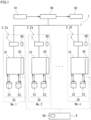
- RF battery system 1 includes a plurality of banks 2, power conversion devices (PCS: Power Conditioning System) 7 respectively provided in plurality of banks 2, and a battery control device (BMS: Battery Management System) 6.
- PCS Power Conditioning System
- BMS Battery Management System
- Each bank 2 includes a battery cell 10.
- RF battery system 1 is representatively connected to an external power source 91 and an external load 92 via a transformer facility 90.
- RF battery system 1 can be charged with electric power supplied from power source 91 and discharge the charged electric power to load 92.
- Power source 91 is a power generation facility using natural energy such as solar power and wind power or other general power plants.
- Load 92 is a power system, a consumer, or the like.
- RF battery system 1 is used for the purpose of load leveling, the purpose of instantaneous voltage drop compensation, an emergency power source, and the like, and the purpose of output smoothing of natural energy power generation, for example.
- One feature of RF battery system 1 of the embodiment is as follows.
- plurality of banks 2 not all of the SOCs of the banks are aligned with each other, and the SOCs of some banks are shifted from each other.
- plurality of banks 2 include a first bank 2a and a second bank 2b.
- a controller 60 that controls the SOC of each bank 2 is included. Controller 60 performs control such that the SOC of second bank 2b is different from the SOC of first bank 2a.
- a basic configuration of banks 2 constituting RF battery system 1 is described first below. Then, the features of RF battery system 1 are described in detail.
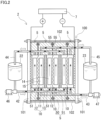
- Bank 2 includes battery cell 10, an electrolytic solution tank 20, and a power conversion device 7. An electrolytic solution is supplied to battery cell 10 from electrolytic solution tank 20. Electrolytic solution tank 20 stores therein the electrolytic solution. Electrolytic solution tank 20 has a positive electrolyte tank 22 and a negative electrolyte tank 23. Positive electrolyte tank 22 stores therein a positive electrolyte. Negative electrolyte tank 23 stores therein a negative electrolyte. Bank 2 performs charging and discharging by supplying the electrolytic solution to battery cell 10 from electrolytic solution tank 20. Bank 2 can function as a secondary battery by itself.
- Battery cell 10 is a cell of a secondary battery. In other words, battery cell 10 performs charging and discharging by the supply of the electrolytic solution. As shown in Fig. 2 , battery cell 10 has a positive electrode 14, a negative electrode 15, and a membrane 11 disposed between positive electrode 14 and negative electrode 15. Battery cell 10 is separated into a positive cell 12 and a negative cell 13 by membrane 11. Positive electrode 14 is built in positive cell 12. Negative electrode 15 is built in negative cell 13.
- the positive electrolyte is supplied to positive cell 12.
- the negative electrolyte is supplied to negative cell 13.
- Bank 2 of this example includes a supply pipe 42 and a return pipe 44 that connect battery cell 10 and positive electrolyte tank 22 to each other.
- Bank 2 includes a supply pipe 43 and a return pipe 45 that connect battery cell 10 and negative electrolyte tank 23 to each other.
- Pumps 46, 47 are provided in each of supply pipes 42, 43.
- the positive electrolyte is supplied to positive cell 12 from positive electrolyte tank 22 through supply pipe 42 by pump 46.
- the positive electrolyte that has passed through positive cell 12 and been discharged from positive cell 12 is returned to positive electrolyte tank 22 through return pipe 44.
- the negative electrolyte is supplied to negative cell 13 from negative electrolyte tank 23 through supply pipe 43 by pump 47.
- the negative electrolyte that has passed through negative cell 13 and been discharged from negative cell 13 is returned to negative electrolyte tank 23 through return pipe 45.
- the electrolytic solution circulates between electrolytic solution tank 20 and battery cell 10.
- Bank 2 may include a cell stack 100 in which plurality of battery cells 10 are stacked.
- Cell stack 100 includes a stacked body in which a cell frame 5, positive electrode 14, membrane 11, and negative electrode 15 are repeatedly stacked in the stated order, and two end plates 101 that sandwich the stacked body from both sides.
- Cell stack 100 is configured by sandwiching the stacked body by two end plates 101 and fastening the place between end plates 101 by fastening members 102.
- cell stack 100 has a structure in which a predetermined number of battery cells 10 constitute a sub stack (not shown) and a plurality of sub stacks are stacked.
- Cell frame 5 has a bipolar plate 51 disposed between positive electrode 14 and negative electrode 15, and a frame body 50 provided around bipolar plate 51. On the inner side of frame body 50, positive electrode 14 and negative electrode 15 are housed across bipolar plate 51.
- One battery cell 10 is configured by disposing positive electrode 14 and negative electrode 15 across membrane 11 between bipolar plates 51 of adjacent cell frames 5.
- a seal member 55 is disposed between frame bodies 50 in order to suppress the leakage of the electrolytic solution from battery cells 10.
- Bank 2 may include plurality of cell stacks 100. Plurality of cell stacks 100 may be connected in series or parallelly connected. When bank 2 includes plurality of cell stacks 100, one electrolytic solution tank 20 or plurality of electrolytic solution tanks 20 may be included for plurality of cell stacks 100. When one electrolytic solution tank 20 is included, one positive electrolyte tank 22 and one negative electrolyte tank 23 are included. When plurality of electrolytic solution tanks 20 are included, plurality of positive electrolyte tanks 22 and plurality of negative electrolyte tanks 23 are included. When bank 2 includes plurality of battery cells 10, electrolytic solution with uniform SOC is supplied to each battery cell 10.
- the electrolytic solution is representatively a solution including an active material ion.
- the active material ion is an ion that functions as an active material.
- a metal ion of which valence changes by oxidoreduction can be used as the active material ion.
- the active material ion is an ion of an element selected from a group consisting of manganese, vanadium, iron, chromium, titanium, and zinc, for example.
- the electrolytic solution of at least one of the positive electrolyte and the negative electrolyte has the following characteristics.
- the electrolytic solution is an electrolytic solution in which a side reaction product can be generated by a side reaction in a high SOC region in which the SOC is high and the side reaction product can be redissolved by a reversible reaction in a region in which the SOC is relatively low, for example.
- the electrolytic solution is an electrolytic solution in which a side reaction product can be generated by a side reaction in a low SOC region in which the SOC is low and the side reaction product can be redissolved by a reversible reaction in a region in which the SOC is relatively high. Even when a side reaction occurs, the electrolytic solution as above can be recovered to the original state by redissolving the side reaction product by the control of the SOC.
- the side reaction product generated by the side reaction is a deposit of the active material ion, for example.
- the electrolytic solution is an electrolytic solution containing a manganese ion, for example.
- the manganese oxide may be deposited in the positive electrolyte in the high SOC region at the time of charging.
- the manganese oxide may be decomposed into a manganese ion and redissolved into the positive electrolyte in the low SOC region.
- the positive electrolyte is an electrolytic solution containing a manganese ion
- the negative electrolyte is an electrolytic solution containing a titanium ion, for example.
- Power conversion device 7 controls the charging and discharging of battery cell 10.
- Battery cell 10 performs charging and discharging via power conversion device 7.
- Each bank 2 can independently control the charging and discharging of battery cell 10 by power conversion device 7.
- Power conversion device 7 is controlled by a battery control device 6.
- An AC/DC conversion device can be used for power conversion device 7, for example.
- each bank 2 includes a monitor cell 30 for measuring the SOC.
- An electrolytic solution in common with the electrolytic solution supplied to battery cell 10 is supplied to monitor cell 30.
- the electrolytic solution supplied to battery cell 10 and the electrolytic solution supplied to monitor cell 30 are supplied from same electrolytic solution tank 20.
- a single cell having basically the same configuration as battery cell 10 described above can be used as monitor cell 30.
- Monitor cell 30 does not perform charging and discharging.
- the SOC of bank 2 can be obtained from open circuit voltage (OCV) of monitor cell 30.
- Monitor cell 30 may be provided separately from battery cell 10 or some cells of cell stack 100 described above may be configured as the monitor cell. When monitor cell 30 is separately provided, monitor cell 30 may be provided on the upstream side of battery cell 10. The electrolytic solution before being charged or discharged by battery cell 10 is supplied to monitor cell 30 provided upstream from battery cell 10. This is because the SOC detected by monitor cell 30 differs from the SOC of the electrolytic solution in electrolytic solution tank 20 when monitor cell 30 is provided downstream from battery cell 10. When bank 2 includes plurality of battery cells 10, monitor cell 30 measures an average value of the SOCs of plurality of battery cells 10.
- RF battery system 1 includes plurality of banks 2 and battery control device 6.
- the number of banks 2 is four or more, for example.
- the battery capacity of the entire system can be increased as the number of banks 2 becomes larger.
- the number of banks 2 may be further 11 or more or 16 or more.
- the upper limit of the number of banks 2 is 100 or less or further 50 or less, for example.
- the number of banks 2 may be 11 or more and 100 or less, or 16 or more and 50 or less, for example.
- each bank 2 is indicated as No. 1, No. 2 ⁇ No. n.
- n is a natural number.
- Plurality of banks 2 include plurality of first banks 2a and one or more second banks 2b.
- First banks 2a are banks controlled to be in the first SOC out of plurality of banks 2.
- Second bank 2b is a bank other than first banks 2a out of plurality of banks 2.
- Second bank 2b is a bank controlled to be in the second SOC different from the first SOC.
- first banks 2a and second bank 2b are not physically fixed.
- Individual banks 2 may function as first banks 2a or second banks 2b. Therefore, there may be a state in which all banks 2 are operating as first banks 2a, in other words, a state in which only plurality of first banks 2a exist during the operation of RF battery system 1 or at a certain time point.
- RF battery system 1 of this embodiment is not only placed in a state in which second bank 2b is constantly included but also includes being in a state in which one or more second banks 2b are included only at a certain time point during the operation.
- First bank 2a is a bank that performs charging and discharging with respect to external power source 91 or load 92.
- the SOC of first bank 2a fluctuates in accordance with charging and discharging.
- the SOC of first bank 2a is controlled to be in the first SOC at the time of charging and discharging.
- the first SOC has a first SOC range.
- the first SOC is a particular value within the first SOC range.
- the first SOC range is a numerical value width defined by an upper limit and a lower limit of the first SOC. In other words, the first SOC range is a difference between the upper limit and the lower limit of a range possible for the first SOC.
- the first SOC range is a range obtained by expanding a usage range of a normal SOC.
- the usage range of the normal SOC is an SOC range in which a side reaction hardly occurs and a side reaction product is hardly generated.
- the usage range of the normal SOC is an SOC range in which the deterioration of the electrolytic solution due to a side reaction hardly progresses and the battery performance can be maintained.
- the SOC range in which the side reaction product is hardly generated described above is a range in which the rate of the active material consumed by the generation of the side reaction product is 10 mol% or less where the total amount of elements serving as the active material included in the electrolytic solution is 100 mol% when charging and discharging are performed for one week within a certain SOC range, for example.
- the period of time for charging and discharging within the SOC range be two weeks or further one month. It is preferred that the rate of the active material consumed by the generation of the side reaction product be 5 mol% or less, or further 1 mol% or less.
- the range obtained by expanding the usage range of the normal SOC includes an SOC range in which a side reaction occurs and a side reaction product is generated by charging or discharging in addition to the usage range of the normal SOC.
- the first SOC includes at least one of a high SOC region and a low SOC region.
- the high SOC region is a region in which the SOC is higher than an upper limit value of the usage range of the normal SOC.
- the low SOC region is a region in which the SOC is lower than a lower limit value of the usage range of the normal SOC.
- a side reaction product may be generated in the high SOC region and the low SOC region.
- the first SOC is a range obtained by combining the usage range of the normal SOC and at least one of the high SOC region and the low SOC region.
- the usage range of the normal SOC described above differs depending on the electrolytic solution to be used.
- the usage range of the normal SOC is obtained in advance by a test using the electrolytic solution to be used.
- the range expanded from the usage range of the normal SOC in other words, the range of each of the high SOC region and the low SOC region only needs to be set as appropriate.
- the battery capacity of first bank 2a increases by expanding the usage range of the SOC in first bank 2a. As a result, the energy density of the entire system can be enhanced.
- the range of the high SOC region or the range of the low SOC region is 5% or more, further 10% or more, or 15% or more of the usage range of the normal SOC, for example.
- the usage range described above is a difference between the upper limit and the lower limit of the usage range.
- the usage range of the normal SOC is from 20% to 80%
- the range of the high SOC region is 10% of the usage range
- the usage range of the SOC obtained by combining the usage range of the normal SOC and the high SOC region is from 20% to 86%.
- the usage range of the SOC is expanded by 10% as compared to the usage range of the normal SOC, and hence the battery capacity of first bank 2a is increased by 10%.
- the usage range of the SOC is from 14% to 80%.
- the battery capacity of first bank 2a increases by 10% in this case as well. The reason the energy density of the entire system improves is described in detail in the section of ⁇ Trial Calculation Example of Energy Density> described below.
- the number of first banks 2a is 10 or more, or further 15 or more, for example.
- the battery capacity is secured more easily as the entire system as the number of first banks 2a becomes greater.
- the plurality of first banks 2a are controlled such that the SOCs of first banks 2a are not shifted from each other at the time of charging and discharging. In other words, all of the SOCs of first banks 2a are controlled to be aligned with each other. Specifically, the difference in the SOC between first banks 2a is less than ⁇ 2%, or further ⁇ 1% or less. The difference in the SOC between first banks 2a is a difference between an average value of the SOCs of all first banks 2a and the value of the SOC of each first bank 2a.
- Second bank 2b is a bank that performs recovery work of the electrolytic solution.
- the SOC of second bank 2b is controlled to be the second SOC.
- the second SOC has a second SOC range.
- the second SOC is a particular value within the second SOC range.
- the second SOC range is a numerical value width defined by an upper limit and a lower limit of the second SOC. In other words, the second SOC range is a difference between the upper limit and the lower limit of a range possible for the second SOC.
- the second SOC range is an SOC range in which the side reaction product described above can be redissolved by a reversible reaction.
- the SOC range in which the side reaction product described above is redissolved differs depending on the electrolytic solution to be used.
- the SOC range in which the side reaction product is redissolved is obtained in advance by a test using the electrolytic solution to be used. For example, when the side reaction product is redissolved in a region in which the SOC is 30% or less, the second SOC only needs to be 30% or less and may be 20% or less. In this case, as the SOC becomes lower, the speed of the reversible reaction becomes higher, and hence the side reaction product tends to be easily redissolved. When the side reaction product is redissolved in a region in which the SOC is 70% or more, the second SOC only needs to be 70% or more and may be 80% or more.
- the second SOC only needs to be a particular value within the SOC range in which the side reaction product described above is redissolved and may partially overlap with the first SOC range described above.
- the first SOC range is from 20% to 86%
- the second SOC range may be from 20% to 30% or may be from 0 to 30%.
- second bank 2b may perform charging and discharging in the overlapping range.
- battery cell 10 can also perform charging and discharging during the recovery work of the electrolytic solution. Needless to say, battery cell 10 does not necessarily need to perform charging and discharging in second bank 2b.
- the second SOC range is smaller than the first SOC range, for example.
- the second SOC range may be 30% or less of the first SOC range, for example.
- 30% of the first SOC range is about 20%.
- the second SOC range is from 20% to 30% and the difference between the upper limit and the lower limit thereof is 10%, the second SOC range is about 15% of the first SOC range. In other words, the second SOC range is 30% or less of the first SOC range.
- the number of second banks 2b is smaller than the number of first banks 2a.
- a rate x of the number of second banks 2b to the total number of plurality of banks 2 is 30% or less, for example.
- second banks 2b are smaller in number.
- first banks 2a are greater in number.
- Rate x may be 20% or less, or further 10% or less, for example.
- An example of specific ranges of the first SOC and the second SOC is shown.
- an example of a case where a titanium/manganese-based electrolytic solution is used as the electrolytic solution is shown.
- a positive electrolyte contains a manganese ion
- a negative electrolyte contains a titanium ion.
- the usage range of the normal SOC is roughly from 20% to 80%.
- manganese oxide may be deposited in the positive electrolyte as a side reaction product.
- the range of the high SOC region is 3% or more, further 6% or more, or 12% or more, for example. As the range of the high SOC region becomes greater, a usable battery capacity increases because the usage range of the SOC becomes expanded than the usage range of the normal SOC.
- the usage range of the SOC at the time of charging and discharging in other words, the first SOC range is from 20% to 83%, further from 20% to 86%, or from 20% to 92%, for example.
- the upper limit of the first SOC range is 100%, or further 95%, for example. When the upper limit of the first SOC range is 95%, the decrease in battery efficiency due to the increase of internal resistance is easily suppressed.
- the SOC range in which manganese oxide in the positive electrolyte can be redissolved by a reversible reaction is roughly 30% or less.
- the SOC range in which the side reaction product can be redissolved by the reversible reaction that is, the second SOC range is from 0% to 30% or further from 0% to 20%, for example.
- the second SOC may be lower than the usage range of the normal SOC described above.
- the second SOC may be less than 20%.
- the second SOC may partially overlap with the usage range of the normal SOC described above.
- the second SOC may be from 20% to 30%, for example.
- Another electrolytic solution is a vanadium-based electrolytic solution, for example.
- a vanadium-based electrolytic solution both of a positive electrolyte and a negative electrolyte contain a vanadium ion.
- the valences of the vanadium ion of the positive electrolyte and the vanadium ion of the negative electrolyte are different from each other.
- the usage range of the normal SOC is roughly from 5% to 95%.
- Battery control device 6 not only controls the operation of RF battery system 1 but also includes controlling actions necessary for monitoring and improving the state of each bank 2. Battery control device 6 independently manages the charging and discharging of each bank 2. Therefore, it becomes possible to perform the recovery work of the electrolytic solution of second bank 2b while performing charging or discharging in first banks 2a. Battery control device 6 issues an action command to power conversion device 7 of each bank 2. Power conversion device 7 of each bank 2 controls the charging and discharging of battery cell 10 based on the action command from battery control device 6. Battery control device 6 issues a charging/discharging command to power conversion device 7 of each first bank 2a when charging and discharging are performed with respect to power source 91 or load 92, for example.
- first bank 2a battery cell 10 performs charging or discharging in accordance with the requested charging amount or discharging amount.
- Battery control device 6 issues a recovery work command to power conversion device 7 of second bank 2b.
- second bank 2b the recovery work of the electrolytic solution is executed.
- Battery control device 6 is representatively configured by a computer.
- the computer includes a processor, a memory, a timer, and the like.
- the memory has a control program to be executed by the processor and various data stored therein.
- the processor reads out and executes the control program stored in the memory.
- the program includes an instruction group relating to processing by controller 60.
- Battery control device 6 has controller 60. Controller 60 controls power conversion device 7 and controls the SOC of each bank 2. Controller 60 performs SOC control that controls the SOC of second bank 2b to be the second SOC different from the first SOC. It is preferred that the second SOC be different from the first SOC by ⁇ 2% or more. Therefore, in the SOC control, the SOC of second bank 2b is controlled to be shifted from the SOC of first bank 2a by ⁇ 2% or more. A state in which the difference between the SOC of first bank 2a and the SOC of second bank 2b is ⁇ 2% or more can be realized by intentionally shifting the SOC of second bank 2b. The second SOC may be different from the first SOC by ⁇ 3% or more or may be further different from the first SOC by ⁇ 4% or more.
- the SOC of second bank 2b is controlled to be the second SOC different from the first SOC by the SOC control described above.
- the SOC of second bank 2b is controlled to be the second SOC for a certain amount of time.
- the side reaction product in the electrolytic solution of second bank 2b is redissolved.
- the electrolytic solution of second bank 2b can be recovered.
- the decrease in the battery performance in second bank 2b can be improved.
- Second bank 2b may perform charging and discharging within the second SOC range described above or may stand by or stop without performing charging and discharging.
- the amount of time by which the SOC of second bank 2b is maintained at the second SOC after reaching the second SOC is an amount of time it takes for the side reaction product in the electrolytic solution of second bank 2b to be redissolved and for the electrolytic solution to recover to the original state or more.
- the amount of time maintained in the second SOC may be one minute or more and 24 hours or less, further two hours or more and 16 hours or less, or four hours or more and 12 hours or less, for example.
- the pump that circulates the electrolytic solution may be stopped or may not be stopped in second bank 2b that does not perform charging and discharging after the SOC of second bank 2b reaches the second SOC. By stopping the pump, the electric power consumption by the pump can be reduced.
- Controller 60 may perform rotation control so as to include the time period set to the first SOC and the time period set to the second SOC for each of plurality of banks 2.
- bank 2 is the bank that performs charging and discharging.
- bank 2 is the bank that performs the recovery work of the electrolytic solution.
- each bank 2 there are a time period in which each bank 2 is first bank 2a that performs charging and discharging and a time period in which each bank 2 is second bank 2b that performs the recovery work of the electrolytic solution.
- certain bank 2 functions as first bank 2a
- another bank 2 functions as second bank 2b
- certain bank 2 transitions from a state of first bank 2a to a state of second bank 2b
- another bank 2 transitions from a state of second bank 2b to a state of first bank 2a. It becomes possible to perform the recovery work of the electrolytic solution in rotation for all of plurality of banks 2 by switching each bank 2 to second bank 2b in turn by every predetermined amount of time by the rotation control described above.
- the time period set to the first SOC is set to a time period within the amount of time it takes for the generation amount of the side reaction product in the electrolytic solution in first bank 2a to reach a predetermined amount, for example.
- a predetermined amount for example.
- the time period set to the second SOC is set to an amount of time it takes for the side reaction product in the electrolytic solution of second bank 2b to be redissolved and for the electrolytic solution of second bank 2b to recover to the original state or more.
- the electrolytic solution recovers to the original state means a state in which the generation amount of the side reaction product in the electrolytic solution is a certain amount or less.
- the amount of time it takes for the electrolytic solution to recover to the original state is obtained in advance by a test with use of the electrolytic solution to be used.
- a rate y of the amount of time set to the second SOC to the total amount of time of the amount of time set to the first SOC and the amount of time set to the second SOC is 30% or less, for example.
- rate y of the amount of time set to the second SOC is 30% or less, the amount of time functioning as second bank 2b is short. In other words, the amount of the recovery work time of the electrolytic solution in each bank 2 is relatively short.
- Rate y may be 20% or less, or further 10% or less, for example.
- the total number of plurality of banks 2 is 11.
- the number of first banks 2a is 10.
- the number of second banks 2b is 1.
- rate x of the number of second banks 2b is 1/11 ⁇ 9.1%.
- Each of banks 2 is set to No. 1, No. 2 ⁇ No. 11.
- out of plurality of banks 2, No. 1 to No. 10 are first banks 2a controlled to be in the first SOC, and remaining No. 11 is second bank 2b controlled to be in the second SOC.
- Each of banks 2 is periodically switched to second bank 2b in turn.
- the time period set to the second SOC is one day.
- No. 11 is switched from second bank 2b to first bank 2a after one day passes from a certain time. Any of No. 1, No. 2 ⁇ No. 10 is switched from first bank 2a to second bank 2b in place of No. 11. Here, No. 10 is switched to second bank 2b. At this time, No. 1 to No. 9 and No. 11 excluding No. 10 are first banks 2a. The number of first banks 2a and the number of second banks 2b do not change. When another day passes, No. 10 is switched to first bank 2a, and No. 9 is switched to second bank 2b. The recovery work of the electrolytic solution can be performed for all banks 2 by performing switching from first bank 2a to second bank 2b in turn in the order of No. 11, No. 10, No. 9, ⁇ No. 1, No.
- a time period in which particular bank 2 is continuously set to be the first SOC is ten days.
- the amount of time charging and discharging is possible by first bank 2a is ten days.
- a cycle from when individual banks 2 changes from the state of second bank 2b to the state of second bank 2b again is 11 days.
- Rate y of the amount of time set to the second SOC to the total amount of time of the amount of time set to the first SOC and the amount of time set to the first SOC is 1(day)/11(day) ⁇ 0.091.
- Controller 60 may perform transition control that causes particular first bank 2a out of plurality of first banks 2a to transition from the first SOC to the second SOC.
- the expression of "causing transition from the first SOC to the second SOC" means to switch particular first bank 2a to second bank 2b.
- the SOC of particular first bank 2a is higher than the second SOC, particular first bank 2a is discharged, and the SOC of particular first bank 2a is lowered to the second SOC.
- the SOC of particular first bank 2a is lower than the second SOC, particular first bank 2a is charged, and the SOC of particular first bank 2a is raised to the second SOC.
- the transition control performs one of first transition control, second transition control, and third transition control shown below, for example.
- the first transition control performs charging or discharging from particular first bank 2a to second bank 2b.
- the second transition control preferentially discharges or charges particular first bank 2a as compared to other banks 2 when discharging or charging is performed with respect to external power source 91 or load 92.
- particular first bank 2a is discharged or charged by a value that is 1/(1-x) times or more of an average value obtained by dividing the discharging amount or the charging amount to the plurality of first banks 2a by the total number of plurality of banks 2.
- x represents a rate of the number of second banks 2b to the total number of plurality of banks 2.
- the total number of plurality of banks 2 is 11.
- the number of first banks 2a after the transition is 10.
- the number of second banks 2b after the transition is 1.
- Rate x of the number of second banks 2b is 1/11 ⁇ 0.091.
- 1/(1-x) is 1.1.
- the rated output of one bank 2 is 100 kW.
- No. 11 is switched from first bank 2a to second bank 2b and transitions from the first SOC to the second SOC from a state in which No. 1 to No. 11 are first banks 2a described in the example of the rotation control.
- the allocation of the discharging amount to No. 11 is increased so as to preferentially discharge No. 11.
- No. 11 is discharged by a value exceeding an average value obtained by dividing the value of the discharging amount to plurality of first banks 2a by the number of all banks 2. For example, when a discharging command for 1000 kW is received, No. 11 is discharged by a rated output of 100 kW. No. 1 to No.
- a case where one day has passed from a certain time is conceived as described in the example of the rotation control described above.
- a case where transition from the first SOC to the second SOC is performed and switching from first bank 2a to second bank 2b is performed for No. 10 is conceived.
- the allocation of the discharging amount to No. 10 is increased so as to preferentially discharge No. 10.
- No. 10 is discharged by a value equal to or more than an average value obtained by dividing the value of the discharging amount to plurality of first banks 2a by the number of first banks 2a. For example, when a discharging command for 550 kW is received, No.
- No. 10 is discharged by a rated output of 100 kW. At this time, it is considered that No. 11 has not finished transitioning from the second SOC to the first SOC, and No. 11 is not discharged.
- Out of first banks 2a, No. 1 to No. 9 excluding No. 10 are discharged by a value obtained by averaging the remaining discharging amount of 450 kW, in other words, 50 kW.
- No. 10 is preferentially discharged by a value that is 1.1 times or more of the average value described above, and hence the amount of transition time can be caused to be shorter.
- No. 11 is caused to transition from the second SOC to the first SOC and switched from second bank 2b to first bank 2a.
- the allocation of the charging amount to No. 11 is increased so as to preferentially charge No. 11.
- No. 11 is charged by a value equal to or more than an average value obtained by dividing the value of the charging amount to plurality of first banks 2a by the number of first banks 2a. For example, when a charging command for 550 kW is received, No. 11 is charged by a rated output of 100 kW. At this time, No. 10 is not charged.
- the third transition control preferentially discharges or charges particular first bank 2a as compared to other banks 2 when discharging or charging is performed with respect to external power source 91 or load 92.
- particular first bank 2a is discharged or charged by a value that is 1/(1-y) times or more of an average value obtained by dividing the discharging amount or the charging amount to the plurality of first banks 2a by the total number of plurality of banks 2.
- y represents the rate of the amount of time set to the second SOC to the total amount of time of the amount of time set to the first SOC and the amount of time set to the second SOC.
- the total number of plurality of banks 2 is 11.
- the number of first banks 2a after the transition is 10.
- the number of second banks 2b after the transition is 1.
- rate y of the amount of time set to the second SOC to the total amount of time of the amount of time set to the first SOC and the amount of time set to the second SOC is 1 (day)/11 (day) ⁇ 0.091.
- 1/(1-y) is 1.1.
- the rated output of one bank 2 is 100 kW.
- the third transition control a case where transition from the first SOC to the second SOC is performed and switching from first bank 2a to second bank 2b is performed for No. 11 is conceived.
- the basic concept in which No. 11 is discharged by a value exceeding an average value obtained by dividing the value of the discharging amount to plurality of first banks 2a by the number of all banks 2 is similar to that of the second transition control. For example, when a discharging command for 1000 kW is received, No. 11 is discharged by a rated output of 100 kW. No. 1 to No. 10 that are first banks 2a are discharged by a value obtained by averaging the remaining discharging amount of 900 kW, in other words, 90 kW.
- an average value obtained by dividing the discharging command value by the total number of banks 2 is 1000/11-90.9 kW.
- No. 11 is preferentially discharged by a value that is 1.1 times or more of the average value described above, and hence the amount of transition time can be caused to be shorter.
- each bank 2 includes a counter 80 that quantifies the generation amount of the side reaction product in the electrolytic solution.
- counter 80 a timing for causing transition from first bank 2a to second bank 2b by controller 60 can be suitably determined based on the generation amount of the side reaction product.
- the generation amount of the side reaction product can be obtained by optical characteristics, physical properties, and the like of the electrolytic solution or obtained as functions of a value of the SOC, the temperature of the electrolytic solution, and the amount of time, for example.
- the optical characteristics of the electrolytic solution include color, transparency, and the like of the electrolytic solution, for example.
- the color and the transparency may change when a side reaction product is generated. As the generation amount of the side reaction product becomes greater, the change in the color and the transparency tends to become greater. Therefore, the generation amount of the side reaction product can be quantitatively obtained by measuring the optical characteristics of the electrolytic solution.
- the optical characteristics of the electrolytic solution can be measured by performing image processing of an image photographed by a camera, or by using a spectrophotometer, for example.
- the physical properties of the electrolytic solution include viscosity, conductivity, density, and the like, for example.
- the viscosity, the conductivity, and the density may change when a side reaction product is generated. As the generation amount of the side reaction product becomes greater, the change in the viscosity, the conductivity, and the density tends to become greater. Therefore, the generation amount of the side reaction product can also be quantitatively obtained by measuring the physical properties of the electrolytic solution.
- the generation amount of a side reaction depends on each of parameters of the value of the SOC, the temperature of the electrolytic solution, and the amount of time. As the SOC becomes higher or the SOC becomes lower, a side reaction occurs more easily, and the generation amount of a side reaction product increases. As the temperature of the electrolytic solution becomes higher, the speed of the side reaction becomes greater, and the generation amount of the side reaction product increases. As the amount of time maintained in the SOC in which the side reaction occurs becomes longer, the generation amount of the side reaction product increases. Therefore, the generation amount of the side reaction product can be quantitatively obtained as the function of each parameter described above.
- the SOC is managed by electrical information such as the quantity of electricity and the amount of charging/discharging time at the time of charging or discharging in each bank 2.
- a trial calculation of the energy density in RF battery system 1 of the embodiment has been performed.
- the trial calculation of the energy density of each of an embodiment model using the embodiment and a comparative model of a related-art design is performed and compared, and the energy densities are compared with each other.
- the energy density is obtained as the battery capacity per unit of the electrolytic solution amount.
- the comparative model is an RF battery system including a plurality of banks. In the RF battery system, all the banks perform charging and discharging. In other words, the comparative model is different from the embodiment in that all the banks are the first banks and the second bank is not included.
- the comparative model sets the usage range of the SOC to 20% to 80%.
- the effective number of banks is the number of banks used in charging and discharging. In the comparative model, the effective number of banks is the same as the total number of banks.
- the embodiment model includes the same number of banks as the comparative model.
- the number of the first banks is 15.
- the number of the second banks is 1.
- the embodiment model sets the usage range of the SOC to 20% to 86%.
- the usage range of the SOC of the embodiment model is expanded from the comparative model by 10%. Therefore, the time capacity of the embodiment model increases by 10% as compared to the comparative model.
- the effective number of banks is the same as the number of the first banks. In other words, the effective number of banks is a value obtained by subtracting the number of the second banks from the total number of banks.
- ⁇ represents an expanded width of the time capacity obtained by expanding the usage range of the SOC.
- the effective number of banks is smaller than that of the comparative model, but the energy density improves as compared to the comparative model.
- the reason thereof is because the time capacity is increased in the embodiment model because the usage range of the SOC is expanded as compared to the comparative model. From a calculation expression of the energy density, it can be said that an effect of improving the energy density is easily obtained when the number of the first banks is greater.
- the condition in which the effect is obtained more is when a total number of banks n is great or when expanded width ⁇ of the time capacity is great, for example. Specifically, it is more effective when number of banks n is 30 or more, for example, or when the expanded width ⁇ is 20% or more, for example.
- RF battery system 1 of the embodiment described above is capable of improving the decrease in battery characteristics due to the side reaction while being able to realize the high energy density from the following reasons.
Landscapes
- Life Sciences & Earth Sciences (AREA)
- Engineering & Computer Science (AREA)
- Manufacturing & Machinery (AREA)
- Sustainable Development (AREA)
- Sustainable Energy (AREA)
- Chemical & Material Sciences (AREA)
- Chemical Kinetics & Catalysis (AREA)
- Electrochemistry (AREA)
- General Chemical & Material Sciences (AREA)
- Fuel Cell (AREA)
Abstract
Description
- The present disclosure relates to a redox flow battery system.
- This application claims priority from
Japanese Patent Application No. 2021-102299 filed on June 21, 2021 -
PTL 1 discloses an operation method of a redox flow battery system that performs charging and discharging by supplying a positive electrolyte and a negative electrolyte to a battery cell. InPTL 1, it is described that a variation in voltage between a plurality of banks is controlled in the redox flow battery system including the banks. - PTL 1:
Japanese Patent Laying-Open No. 2006-40648 - A redox flow battery system of the present disclosure includes: a plurality of banks; a power conversion device provided in each of the plurality of banks; and a controller that controls a state of charge of each of the plurality of banks by controlling the power conversion device. In the redox flow battery system, each of the plurality of banks includes a battery cell that performs charging and discharging by the supply of an electrolytic solution, the plurality of banks include: a plurality of first banks controlled to be in a first state of charge; and one or more second banks excluding the first banks, and the controller controls a state of charge of the second bank to be a second state of charge different from the first state of charge.
-
-
Fig. 1 is a schematic configuration diagram showing a configuration of a redox flow battery system according to an embodiment. -
Fig. 2 is a schematic configuration diagram showing a basic configuration of a bank. - It is required to enhance the energy density in a redox flow battery system. When the energy density can be increased, the battery capacity can be enhanced. However, when the energy density is to be increased, a side reaction easily occurs at the time of charging or discharging. There is a possibility that a decrease in the battery performance such as the deterioration of an electrolytic solution is caused by the side reaction.
- In general, in a redox flow battery, the usage range of the state of charge (SOC) is limited to suppress the decrease in the battery performance due to a side reaction. The technique described in
PTL 1 causes the SOCs of the banks to be as equal as possible by performing voltage control that reduces the difference in voltage between the banks. In the technique described inPTL 1, operation is performed so as to cause the SOCs of all of the banks to be equal within an SOC range in which a side reaction does not occur. Therefore, the usage range of the SOC cannot be expanded. - An object of the present disclosure is to provide a redox flow battery system capable of improving the decrease in battery performance due to a side reaction while being able to realize high energy density.
- The redox flow battery system of the present disclosure is capable of improving the decrease in the battery performance due to the side reaction while being able to realize high energy density.
- The inventors of the present invention have gained the following insight as a result of intensive research regarding acquisition of high energy density in a redox flow battery and the influence of the acquisition of the high energy density on the battery performance.
- One measure to enhance the energy density of the redox flow battery is to expand the usage range of the SOC. However, when the usage range of the SOC is expanded, a side reaction may occur, and the battery performance may be adversely affected.
- In general, in the redox flow battery, the SOC is managed to be maintained within a certain range in order to suppress the decrease in the battery performance due to a side reaction. In a region in which the SOC is high or a region in which the SOC is low, an active material ion included in the electrolytic solution may be deposited by the side reaction. When the active material ion is deposited, there is a possibility that the active material ion may not function as an active material. The deposition of the active material ion causes the deterioration of the electrolytic solution and the decrease in the battery capacity. A deposit of the active material ion causes the deterioration of a battery cell by adhering to an electrode constituting the battery cell, for example. As above, when charging or discharging is performed in the region in which the SOC is high or the region in which the SOC is low, a side reaction such as the deposition of an active material ion is facilitated. When the generation amount of a side reaction product such as the deposit of the active material ion increases, the battery performance decreases. Thus, in the related-art redox flow battery, control is commonly performed so as to perform charging and discharging within an SOC range in which a side reaction hardly occurs. In other words, the usage range of the SOC is limited.
- The inventors of the present invention have found that it may be possible to dissolute a product generated by a side reaction into the electrolytic solution as an ion again by a reversible reaction. For example, when a deposit of an active material ion is generated by a side reaction in the region in which the SOC is high, it may be possible to cause the deposit to return into an ion again in the region in which the SOC is low. Alternatively, when a deposit of an active material ion is generated by a side reaction in the region in which the SOC is low, it may be possible to cause the deposit to return into an ion again in the region in which the SOC is high. In such case, it becomes possible to redissolve the deposit of the active material ion as an ion by controlling the SOC to be periodically maintained in the region in which the SOC is low or the region in which the SOC is high for a certain amount of time. Therefore, even when a side reaction occurs, it becomes possible to recover the electrolytic solution by redissolving the side reaction product such as the deposit of the active material ion by controlling the SOC. It can be possible to improve the decrease in the battery performance due to a side reaction. However, the control of the SOC for redissolving the side reaction product forcibly controls the SOC into a particular range, and hence cannot perform charging or discharging at the same time. Therefore, the control of the SOC described above needs to be performed when the battery cell is not performing charging and discharging. When the control of the SOC described above is executed, the operation of the redox flow battery is stopped, and hence a restriction occurs in the operation. There is less freedom of operation for a user.
- The inventors of the present invention propose shifting the SOCs between the plurality of banks in the redox flow battery system including the banks in order to realize high energy density. In detail, control is not performed so as to cause the SOCs of all of the banks to be equal, and control is performed such that the SOCs of some banks are different.
- An embodiment of the present disclosure is listed and described first.
- (1) A redox flow battery system according to an embodiment of the present disclosure includes: a plurality of banks; a power conversion device provided in each of the plurality of banks; and a controller that controls a state of charge of each of the plurality of banks by controlling the power conversion device. In the redox flow battery system, each of the plurality of banks includes a battery cell that performs charging and discharging by a supply of an electrolytic solution, the plurality of banks include: a plurality of first banks controlled to be in a first state of charge; and one or more second banks excluding the first banks, and the controller controls a state of charge of the second bank to be a second state of charge different from the first state of charge.
- The redox flow battery system of the present disclosure is capable of improving the decrease in the battery characteristics due to the side reaction while being able to realize high energy density. The state of charge of the bank means the state of charge of a battery cell constituting the bank. When there are a plurality of battery cells, the state of charge of the battery cell is an average value of the states of charge of the plurality of battery cells. The state of charge is simply referred to as an "SOC" below.
- In the redox flow battery system of the present disclosure, the first bank is a bank that performs charging from a power source such as a power generation facility and performs discharging to a load. The SOC of the first bank fluctuates in accordance with charging and discharging. The SOC of the first bank is controlled to be the first SOC. The first SOC is a particular value within a range obtained by expanding the usage range of a normal SOC. The usage range of the normal SOC is an SOC range in which a side reaction hardly occurs and a side reaction product is hardly generated even when charging and discharging are repeated. The second bank is a bank that performs recovery work of the electrolytic solution such as the redissolution of the side reaction product. The SOC of the second bank is controlled to be the second SOC. The second SOC is a particular value within an SOC range in which a product generated by a side reaction can be redissolved by a reversible reaction.
- In the redox flow battery system of the present disclosure, it becomes possible to enhance the energy density by expanding the usage range of the SOC in the first bank. The battery capacity can be secured as the entire system. It becomes possible to recover the electrolytic solution of the second bank by controlling the SOC of the second bank to be the SOC in which the side reaction product is redissolved. Therefore, it becomes possible to improve the decrease in the battery performance due to the side reaction. In the redox flow battery system of the present disclosure, it becomes possible to perform the recovery work of the electrolytic solution of the second bank while performing charging or discharging in the first bank. It becomes possible to perform the recovery work of the electrolytic solution without stopping the system, and hence there are less operation restrictions.
- The expression of "the side reaction product is redissolved" described above is defined as causing the state of the electrolytic solution that has changed by charging or discharging in a particular SOC range to return to the original state in a broad sense. This is not limited to causing a solid deposit to return to an ion in the electrolytic solution and may or may not be associated with changes in phase of gas, solid, and liquid. In the case of an electrolytic solution including a solid active material such as zinc, controlling the amount of electrodeposition thereof is also included. An active material may be deposited on a surface of the electrode by a side reaction. When a deposit due to a side reaction adheres to the electrode, the reactivity of the electrode deteriorates. In other words, the battery performance decreases. A catalyst and the like may be caused to adhere to a surface of the electrode for the purpose of improving the reactivity of the electrode. The decrease in the battery performance is also caused when the deposit due to the side reaction is deposited so as to cover the catalyst and the like. It becomes possible to maintain the state of the surface of the electrode by redissolving the deposit that has adhered to the surface of the electrode. As a result, it becomes possible to suppress the decrease in the battery performance.
- (2) In the redox flow battery system of the present disclosure, the second state of charge may be different from the first state of charge by ±2% or more.
- The redox flow battery system described above controls the SOC of the second bank to be shifted from the SOC of the first bank by ±2% or more. The state in which the difference between the SOC of the first bank and the SOC of the second bank is ±2% or more can be realized by intentionally shifting the SOC of the second bank from the SOC of the first bank.
- (3) In the redox flow battery system of the present disclosure, the first state of charge may have a range of the first state of charge defined by an upper limit and a lower limit, the second state of charge may have a range of the second state of charge defined by an upper limit and a lower limit, and the range of the second state of charge may be 30% or less of the range of the first state of charge.
- The redox flow battery system described above easily performs the recovery work of the electrolytic solution of the second bank.
- (4) In the redox flow battery system of the present disclosure, a rate of a number of the second banks to a total number of the plurality of banks may be 30% or less.
- In the redox flow battery system described above, out of the plurality of banks, the second banks are smaller in number than the first banks. In other words, the first banks are greater in number. The number of the first banks that perform charging and discharging is greater than the number of the second banks that perform the recovery work of the electrolytic solution, and hence the battery capacity is easily secured as the entire system.
- (5) In the redox flow battery system of the present disclosure, the controller may control each of the plurality of banks to include a time period set to the first state of charge and a time period set to the second state of charge.
- The redox flow battery system described above is capable of performing the recovery work of the electrolytic solution for all of the banks. The bank functions as the first bank in the time period set to the first state of charge. The bank functions as the second bank in the time period set to the second state of charge. In other words, there are a time period in which each bank is the first bank that performs charging and discharging and a time period in which each bank is the second bank that performs the recovery work of the electrolytic solution. The recovery work of the electrolytic solution can be performed by each predetermined amount of time for each of the banks.
- (6) In the redox flow battery system according to (5) described above, a rate of an amount of time set to the second state of charge to a total amount of time of an amount of time set to the first state of charge and the amount of time set to the second state of charge may be 30% or less.
- In the redox flow battery system described above, the amount of time the recovery work of the electrolytic solution is performed for each of the banks is set to be relatively short.
- (7) In the redox flow battery system of the present disclosure, when a particular bank out of the plurality of first banks is caused to transition from the first state of charge to the second state of charge, the controller may perform charging or discharging from the particular bank to the second bank.
- In the redox flow battery system described above, it becomes possible to cause a particular bank to transition from the first state of charge to the second state of charge by performing charging or discharging between the banks even when charging or discharging is not performed with respect to an external power source or a load. In the example described above, it becomes possible to perform the transition of the second bank from the second state of charge to the first state of charge at the same time.
- (8) In the redox flow battery system of the present disclosure, a rate of a number of the second banks to a total number of the plurality of banks may be represented by x, and the controller may discharge or charge a particular bank out of the plurality of first banks by a value that is 1/(1-x) times or more of an average value obtained by dividing a value of a discharging amount or a charging amount to the plurality of first banks by the total number of the plurality of banks when the particular bank is caused to transition from the first state of charge to the second state of charge.
- The redox flow battery system described above causes a particular bank to transition to the second bank by preferentially discharging or charging the particular bank as compared to other banks when the plurality of first banks are discharged or charged. Therefore, a shorter amount of transition time is required as compared to a case where all of the banks are charged or discharged by an average value.
- (9) In the redox flow battery system of the present disclosure, a rate of an amount of time set to the second state of charge to a total amount of time of an amount of time set to the first state of charge and the amount of time set to the second state of charge may be represented by y, and the controller may discharge or charge a particular bank out of the plurality of first banks by a value that is 1/(1-y) times or more of an average value obtained by dividing a value of a discharging amount or a charging amount to the plurality of first banks by the total number of the plurality of banks when the particular bank is caused to transition from the first state of charge to the second state of charge.
- The redox flow battery system described above causes a particular bank to transition to the second bank by preferentially discharging or charging the particular bank as compared to other banks when the plurality of first banks are discharged or charged. Therefore, a shorter amount of transition time is required as compared to a case where all of the banks are charged or discharged by an average value.
- (10) In the redox flow battery system of the present disclosure, each of the plurality of banks may have a counter that quantifies a generation amount of a side reaction product in the electrolytic solution.
- The redox flow battery system described above is capable of suitably determining a timing for performing the recovery work of the electrolytic solution.
- (11) In the redox flow battery system according (10) described above, the counter may quantify the generation amount of the side reaction product in the electrolytic solution as a function of each of a value of a state of charge, a temperature of the electrolytic solution, and an amount of time in each of the plurality of banks.
- The redox flow battery system described above is capable of suitably obtaining the generation amount of the side reaction product.
- A specific example of the redox flow battery system of the present disclosure is described with reference to the drawings. The redox flow battery may be referred to as an "RF battery" below. The same reference characters in the drawings indicate the same or equivalent parts.
- The invention is not limited to the exemplifications above and is defined by the scope of claims. All modifications made within the scope and spirit equivalent to those of the claims are intended to be included in the invention.
- With reference to
Fig. 1 andFig. 2 , anRF battery system 1 according to the embodiment is described. As shown inFig. 1 ,RF battery system 1 includes a plurality ofbanks 2, power conversion devices (PCS: Power Conditioning System) 7 respectively provided in plurality ofbanks 2, and a battery control device (BMS: Battery Management System) 6. Eachbank 2 includes abattery cell 10. -
RF battery system 1 is representatively connected to anexternal power source 91 and anexternal load 92 via atransformer facility 90.RF battery system 1 can be charged with electric power supplied frompower source 91 and discharge the charged electric power to load 92.Power source 91 is a power generation facility using natural energy such as solar power and wind power or other general power plants.Load 92 is a power system, a consumer, or the like.RF battery system 1 is used for the purpose of load leveling, the purpose of instantaneous voltage drop compensation, an emergency power source, and the like, and the purpose of output smoothing of natural energy power generation, for example. - One feature of
RF battery system 1 of the embodiment is as follows. In plurality ofbanks 2, not all of the SOCs of the banks are aligned with each other, and the SOCs of some banks are shifted from each other. Specifically, plurality ofbanks 2 include afirst bank 2a and asecond bank 2b. Acontroller 60 that controls the SOC of eachbank 2 is included.Controller 60 performs control such that the SOC ofsecond bank 2b is different from the SOC offirst bank 2a. - A basic configuration of
banks 2 constitutingRF battery system 1 is described first below. Then, the features ofRF battery system 1 are described in detail. -
Individual banks 2 can independently control the charging and discharging ofbattery cells 10.Bank 2 includesbattery cell 10, anelectrolytic solution tank 20, and apower conversion device 7. An electrolytic solution is supplied tobattery cell 10 fromelectrolytic solution tank 20.Electrolytic solution tank 20 stores therein the electrolytic solution.Electrolytic solution tank 20 has apositive electrolyte tank 22 and anegative electrolyte tank 23.Positive electrolyte tank 22 stores therein a positive electrolyte.Negative electrolyte tank 23 stores therein a negative electrolyte.Bank 2 performs charging and discharging by supplying the electrolytic solution tobattery cell 10 fromelectrolytic solution tank 20.Bank 2 can function as a secondary battery by itself. -
Battery cell 10 is a cell of a secondary battery. In other words,battery cell 10 performs charging and discharging by the supply of the electrolytic solution. As shown inFig. 2 ,battery cell 10 has apositive electrode 14, anegative electrode 15, and a membrane 11 disposed betweenpositive electrode 14 andnegative electrode 15.Battery cell 10 is separated into apositive cell 12 and anegative cell 13 by membrane 11.Positive electrode 14 is built inpositive cell 12.Negative electrode 15 is built innegative cell 13. - The positive electrolyte is supplied to
positive cell 12. The negative electrolyte is supplied tonegative cell 13.Bank 2 of this example includes asupply pipe 42 and areturn pipe 44 that connectbattery cell 10 andpositive electrolyte tank 22 to each other.Bank 2 includes asupply pipe 43 and areturn pipe 45 that connectbattery cell 10 andnegative electrolyte tank 23 to each other.Pumps supply pipes positive cell 12 frompositive electrolyte tank 22 throughsupply pipe 42 bypump 46. The positive electrolyte that has passed throughpositive cell 12 and been discharged frompositive cell 12 is returned topositive electrolyte tank 22 throughreturn pipe 44. The negative electrolyte is supplied tonegative cell 13 fromnegative electrolyte tank 23 throughsupply pipe 43 bypump 47. The negative electrolyte that has passed throughnegative cell 13 and been discharged fromnegative cell 13 is returned tonegative electrolyte tank 23 throughreturn pipe 45. In other words, the electrolytic solution circulates betweenelectrolytic solution tank 20 andbattery cell 10. -
Bank 2 may include acell stack 100 in which plurality ofbattery cells 10 are stacked.Cell stack 100 includes a stacked body in which acell frame 5,positive electrode 14, membrane 11, andnegative electrode 15 are repeatedly stacked in the stated order, and twoend plates 101 that sandwich the stacked body from both sides.Cell stack 100 is configured by sandwiching the stacked body by twoend plates 101 and fastening the place betweenend plates 101 by fasteningmembers 102. In general,cell stack 100 has a structure in which a predetermined number ofbattery cells 10 constitute a sub stack (not shown) and a plurality of sub stacks are stacked. -
Cell frame 5 has abipolar plate 51 disposed betweenpositive electrode 14 andnegative electrode 15, and a frame body 50 provided aroundbipolar plate 51. On the inner side of frame body 50,positive electrode 14 andnegative electrode 15 are housed acrossbipolar plate 51. Onebattery cell 10 is configured by disposingpositive electrode 14 andnegative electrode 15 across membrane 11 betweenbipolar plates 51 of adjacent cell frames 5. Aseal member 55 is disposed between frame bodies 50 in order to suppress the leakage of the electrolytic solution frombattery cells 10. -
Bank 2 may include plurality of cell stacks 100. Plurality ofcell stacks 100 may be connected in series or parallelly connected. Whenbank 2 includes plurality ofcell stacks 100, oneelectrolytic solution tank 20 or plurality ofelectrolytic solution tanks 20 may be included for plurality of cell stacks 100. When oneelectrolytic solution tank 20 is included, onepositive electrolyte tank 22 and onenegative electrolyte tank 23 are included. When plurality ofelectrolytic solution tanks 20 are included, plurality ofpositive electrolyte tanks 22 and plurality ofnegative electrolyte tanks 23 are included. Whenbank 2 includes plurality ofbattery cells 10, electrolytic solution with uniform SOC is supplied to eachbattery cell 10. - The electrolytic solution is representatively a solution including an active material ion. The active material ion is an ion that functions as an active material. A metal ion of which valence changes by oxidoreduction can be used as the active material ion. The active material ion is an ion of an element selected from a group consisting of manganese, vanadium, iron, chromium, titanium, and zinc, for example.
- The electrolytic solution of at least one of the positive electrolyte and the negative electrolyte has the following characteristics.
- (1) A side reaction occurs and a side reaction product is generated in accordance with the SOC range at the time of charging or discharging.
- (2) The side reaction product can be redissolved by a reversible reaction.
- The electrolytic solution is an electrolytic solution in which a side reaction product can be generated by a side reaction in a high SOC region in which the SOC is high and the side reaction product can be redissolved by a reversible reaction in a region in which the SOC is relatively low, for example. Alternatively, the electrolytic solution is an electrolytic solution in which a side reaction product can be generated by a side reaction in a low SOC region in which the SOC is low and the side reaction product can be redissolved by a reversible reaction in a region in which the SOC is relatively high. Even when a side reaction occurs, the electrolytic solution as above can be recovered to the original state by redissolving the side reaction product by the control of the SOC. The side reaction product generated by the side reaction is a deposit of the active material ion, for example.
- The electrolytic solution is an electrolytic solution containing a manganese ion, for example. When a positive electrolyte containing manganese ion is used, the manganese oxide may be deposited in the positive electrolyte in the high SOC region at the time of charging. The manganese oxide may be decomposed into a manganese ion and redissolved into the positive electrolyte in the low SOC region. When the positive electrolyte is an electrolytic solution containing a manganese ion, the negative electrolyte is an electrolytic solution containing a titanium ion, for example.
-
Power conversion device 7 controls the charging and discharging ofbattery cell 10.Battery cell 10 performs charging and discharging viapower conversion device 7. Eachbank 2 can independently control the charging and discharging ofbattery cell 10 bypower conversion device 7.Power conversion device 7 is controlled by a battery control device 6. An AC/DC conversion device can be used forpower conversion device 7, for example. - As shown in
Fig. 1 , eachbank 2 includes amonitor cell 30 for measuring the SOC. An electrolytic solution in common with the electrolytic solution supplied tobattery cell 10 is supplied to monitorcell 30. In other words, the electrolytic solution supplied tobattery cell 10 and the electrolytic solution supplied to monitorcell 30 are supplied from sameelectrolytic solution tank 20. A single cell having basically the same configuration asbattery cell 10 described above can be used asmonitor cell 30.Monitor cell 30 does not perform charging and discharging. The SOC ofbank 2 can be obtained from open circuit voltage (OCV) ofmonitor cell 30. -
Monitor cell 30 may be provided separately frombattery cell 10 or some cells ofcell stack 100 described above may be configured as the monitor cell. Whenmonitor cell 30 is separately provided, monitorcell 30 may be provided on the upstream side ofbattery cell 10. The electrolytic solution before being charged or discharged bybattery cell 10 is supplied to monitorcell 30 provided upstream frombattery cell 10. This is because the SOC detected bymonitor cell 30 differs from the SOC of the electrolytic solution inelectrolytic solution tank 20 whenmonitor cell 30 is provided downstream frombattery cell 10. Whenbank 2 includes plurality ofbattery cells 10, monitorcell 30 measures an average value of the SOCs of plurality ofbattery cells 10. - As shown in
Fig. 1 ,RF battery system 1 includes plurality ofbanks 2 and battery control device 6. The number ofbanks 2 is four or more, for example. The battery capacity of the entire system can be increased as the number ofbanks 2 becomes larger. The number ofbanks 2 may be further 11 or more or 16 or more. When the number ofbanks 2 becomes greater, the entire system becomes enormous and the management ofbank 2 becomes complicated. The upper limit of the number ofbanks 2 is 100 or less or further 50 or less, for example. The number ofbanks 2 may be 11 or more and 100 or less, or 16 or more and 50 or less, for example. InFig. 1 , eachbank 2 is indicated as No. 1, No. 2 ··· No. n. Here, n is a natural number. - Plurality of
banks 2 include plurality offirst banks 2a and one or moresecond banks 2b.First banks 2a are banks controlled to be in the first SOC out of plurality ofbanks 2.Second bank 2b is a bank other thanfirst banks 2a out of plurality ofbanks 2.Second bank 2b is a bank controlled to be in the second SOC different from the first SOC. Here,first banks 2a andsecond bank 2b are not physically fixed.Individual banks 2 may function asfirst banks 2a orsecond banks 2b. Therefore, there may be a state in which allbanks 2 are operating asfirst banks 2a, in other words, a state in which only plurality offirst banks 2a exist during the operation ofRF battery system 1 or at a certain time point. In other words, there may be a state in which there are nobanks 2 that function assecond bank 2b and the number ofsecond banks 2b becomes zero.RF battery system 1 of this embodiment is not only placed in a state in whichsecond bank 2b is constantly included but also includes being in a state in which one or moresecond banks 2b are included only at a certain time point during the operation. -
First bank 2a is a bank that performs charging and discharging with respect toexternal power source 91 orload 92. The SOC offirst bank 2a fluctuates in accordance with charging and discharging. The SOC offirst bank 2a is controlled to be in the first SOC at the time of charging and discharging. The first SOC has a first SOC range. The first SOC is a particular value within the first SOC range. The first SOC range is a numerical value width defined by an upper limit and a lower limit of the first SOC. In other words, the first SOC range is a difference between the upper limit and the lower limit of a range possible for the first SOC. The first SOC range is a range obtained by expanding a usage range of a normal SOC. The usage range of the normal SOC is an SOC range in which a side reaction hardly occurs and a side reaction product is hardly generated. In other words, the usage range of the normal SOC is an SOC range in which the deterioration of the electrolytic solution due to a side reaction hardly progresses and the battery performance can be maintained. The SOC range in which the side reaction product is hardly generated described above is a range in which the rate of the active material consumed by the generation of the side reaction product is 10 mol% or less where the total amount of elements serving as the active material included in the electrolytic solution is 100 mol% when charging and discharging are performed for one week within a certain SOC range, for example. It is preferred that the period of time for charging and discharging within the SOC range be two weeks or further one month. It is preferred that the rate of the active material consumed by the generation of the side reaction product be 5 mol% or less, or further 1 mol% or less. For example, when manganese oxide is generated as a side reaction product in a positive electrolyte containing a manganese ion as the active material, manganese is consumed in the generation of the side reaction product. The range obtained by expanding the usage range of the normal SOC includes an SOC range in which a side reaction occurs and a side reaction product is generated by charging or discharging in addition to the usage range of the normal SOC. The first SOC includes at least one of a high SOC region and a low SOC region. The high SOC region is a region in which the SOC is higher than an upper limit value of the usage range of the normal SOC. The low SOC region is a region in which the SOC is lower than a lower limit value of the usage range of the normal SOC. In the high SOC region and the low SOC region, a side reaction product may be generated. The first SOC is a range obtained by combining the usage range of the normal SOC and at least one of the high SOC region and the low SOC region. - The usage range of the normal SOC described above differs depending on the electrolytic solution to be used. The usage range of the normal SOC is obtained in advance by a test using the electrolytic solution to be used. The range expanded from the usage range of the normal SOC, in other words, the range of each of the high SOC region and the low SOC region only needs to be set as appropriate. The battery capacity of
first bank 2a increases by expanding the usage range of the SOC infirst bank 2a. As a result, the energy density of the entire system can be enhanced. The range of the high SOC region or the range of the low SOC region is 5% or more, further 10% or more, or 15% or more of the usage range of the normal SOC, for example. The usage range described above is a difference between the upper limit and the lower limit of the usage range. For example, when the usage range of the normal SOC is from 20% to 80%, the difference between the upper limit and the lower limit is 80%-20%=60%. When the range of the high SOC region is 10% of the usage range, the range of the high SOC region is 60%×10%=6%. The usage range of the SOC obtained by combining the usage range of the normal SOC and the high SOC region is from 20% to 86%. The first SOC range in this case is 86%-20%=66%. In this case, the usage range of the SOC is expanded by 10% as compared to the usage range of the normal SOC, and hence the battery capacity offirst bank 2a is increased by 10%. When the range of the low SOC region is 10% of the usage range, the usage range of the SOC is from 14% to 80%. The first SOC range in this case is 80%-14%=66%. The battery capacity offirst bank 2a increases by 10% in this case as well. The reason the energy density of the entire system improves is described in detail in the section of <Trial Calculation Example of Energy Density> described below. - The number of
first banks 2a is 10 or more, or further 15 or more, for example. The battery capacity is secured more easily as the entire system as the number offirst banks 2a becomes greater. - The plurality of
first banks 2a are controlled such that the SOCs offirst banks 2a are not shifted from each other at the time of charging and discharging. In other words, all of the SOCs offirst banks 2a are controlled to be aligned with each other. Specifically, the difference in the SOC betweenfirst banks 2a is less than ±2%, or further ±1% or less. The difference in the SOC betweenfirst banks 2a is a difference between an average value of the SOCs of allfirst banks 2a and the value of the SOC of eachfirst bank 2a. -
Second bank 2b is a bank that performs recovery work of the electrolytic solution. The SOC ofsecond bank 2b is controlled to be the second SOC. The second SOC has a second SOC range. The second SOC is a particular value within the second SOC range. The second SOC range is a numerical value width defined by an upper limit and a lower limit of the second SOC. In other words, the second SOC range is a difference between the upper limit and the lower limit of a range possible for the second SOC. The second SOC range is an SOC range in which the side reaction product described above can be redissolved by a reversible reaction. - The SOC range in which the side reaction product described above is redissolved differs depending on the electrolytic solution to be used. The SOC range in which the side reaction product is redissolved is obtained in advance by a test using the electrolytic solution to be used. For example, when the side reaction product is redissolved in a region in which the SOC is 30% or less, the second SOC only needs to be 30% or less and may be 20% or less. In this case, as the SOC becomes lower, the speed of the reversible reaction becomes higher, and hence the side reaction product tends to be easily redissolved. When the side reaction product is redissolved in a region in which the SOC is 70% or more, the second SOC only needs to be 70% or more and may be 80% or more. In this case, as the SOC becomes higher, the speed of the reversible reaction becomes higher, and hence the side reaction product tends to be easily redissolved. The second SOC only needs to be a particular value within the SOC range in which the side reaction product described above is redissolved and may partially overlap with the first SOC range described above. For example, when the first SOC range is from 20% to 86%, the second SOC range may be from 20% to 30% or may be from 0 to 30%. When the second SOC range at least partially overlaps with the first SOC range,
second bank 2b may perform charging and discharging in the overlapping range. In other words, insecond bank 2b,battery cell 10 can also perform charging and discharging during the recovery work of the electrolytic solution. Needless to say,battery cell 10 does not necessarily need to perform charging and discharging insecond bank 2b. - The second SOC range is smaller than the first SOC range, for example. The second SOC range may be 30% or less of the first SOC range, for example. For example, when the first SOC range is 66% as described above, 30% of the first SOC range is about 20%. For example, when the second SOC range is from 20% to 30% and the difference between the upper limit and the lower limit thereof is 10%, the second SOC range is about 15% of the first SOC range. In other words, the second SOC range is 30% or less of the first SOC range.
- The number of
second banks 2b is smaller than the number offirst banks 2a. A rate x of the number ofsecond banks 2b to the total number of plurality ofbanks 2 is 30% or less, for example. Out of plurality ofbanks 2,second banks 2b are smaller in number. In other words,first banks 2a are greater in number. The number offirst banks 2a is great, and hence the battery capacity is easily secured as the entire system. Rate x may be 20% or less, or further 10% or less, for example. - An example of specific ranges of the first SOC and the second SOC is shown. Here, an example of a case where a titanium/manganese-based electrolytic solution is used as the electrolytic solution is shown. In the titanium/manganese-based electrolytic solution, a positive electrolyte contains a manganese ion, and a negative electrolyte contains a titanium ion. In the case of the titanium/manganese-based electrolytic solution, the usage range of the normal SOC is roughly from 20% to 80%. In a high SOC region in which the SOC exceeds 80%, manganese oxide may be deposited in the positive electrolyte as a side reaction product. The range of the high SOC region is 3% or more, further 6% or more, or 12% or more, for example. As the range of the high SOC region becomes greater, a usable battery capacity increases because the usage range of the SOC becomes expanded than the usage range of the normal SOC. The usage range of the SOC at the time of charging and discharging, in other words, the first SOC range is from 20% to 83%, further from 20% to 86%, or from 20% to 92%, for example. As the SOC becomes higher, the speed of the side reaction becomes higher, and hence the deposition amount of manganese oxide increases. The upper limit of the first SOC range is 100%, or further 95%, for example. When the upper limit of the first SOC range is 95%, the decrease in battery efficiency due to the increase of internal resistance is easily suppressed.
- The SOC range in which manganese oxide in the positive electrolyte can be redissolved by a reversible reaction is roughly 30% or less. In other words, the SOC range in which the side reaction product can be redissolved by the reversible reaction, that is, the second SOC range is from 0% to 30% or further from 0% to 20%, for example. As the SOC becomes lower, the speed of the reversible reaction becomes higher, and hence the manganese oxide is redissolved more easily. The second SOC may be lower than the usage range of the normal SOC described above. The second SOC may be less than 20%. When the upper limit of the second SOC range is less than 20%, the manganese oxide is redissolved more easily. The second SOC may partially overlap with the usage range of the normal SOC described above. The second SOC may be from 20% to 30%, for example.
- Another electrolytic solution is a vanadium-based electrolytic solution, for example. In the vanadium-based electrolytic solution, both of a positive electrolyte and a negative electrolyte contain a vanadium ion. The valences of the vanadium ion of the positive electrolyte and the vanadium ion of the negative electrolyte are different from each other. In the case of the vanadium-based electrolytic solution, the usage range of the normal SOC is roughly from 5% to 95%.
- Battery control device 6 not only controls the operation of
RF battery system 1 but also includes controlling actions necessary for monitoring and improving the state of eachbank 2. Battery control device 6 independently manages the charging and discharging of eachbank 2. Therefore, it becomes possible to perform the recovery work of the electrolytic solution ofsecond bank 2b while performing charging or discharging infirst banks 2a. Battery control device 6 issues an action command topower conversion device 7 of eachbank 2.Power conversion device 7 of eachbank 2 controls the charging and discharging ofbattery cell 10 based on the action command from battery control device 6. Battery control device 6 issues a charging/discharging command topower conversion device 7 of eachfirst bank 2a when charging and discharging are performed with respect topower source 91 orload 92, for example. Infirst bank 2a,battery cell 10 performs charging or discharging in accordance with the requested charging amount or discharging amount. Battery control device 6 issues a recovery work command topower conversion device 7 ofsecond bank 2b. Insecond bank 2b, the recovery work of the electrolytic solution is executed. - Battery control device 6 is representatively configured by a computer. The computer includes a processor, a memory, a timer, and the like. The memory has a control program to be executed by the processor and various data stored therein. The processor reads out and executes the control program stored in the memory. The program includes an instruction group relating to processing by
controller 60. - Battery control device 6 has
controller 60.Controller 60 controlspower conversion device 7 and controls the SOC of eachbank 2.Controller 60 performs SOC control that controls the SOC ofsecond bank 2b to be the second SOC different from the first SOC. It is preferred that the second SOC be different from the first SOC by ±2% or more. Therefore, in the SOC control, the SOC ofsecond bank 2b is controlled to be shifted from the SOC offirst bank 2a by ±2% or more. A state in which the difference between the SOC offirst bank 2a and the SOC ofsecond bank 2b is ±2% or more can be realized by intentionally shifting the SOC ofsecond bank 2b. The second SOC may be different from the first SOC by ±3% or more or may be further different from the first SOC by ±4% or more. - The SOC of
second bank 2b is controlled to be the second SOC different from the first SOC by the SOC control described above. By maintaining the SOC ofsecond bank 2b to be the second SOC for a certain amount of time, the side reaction product in the electrolytic solution ofsecond bank 2b is redissolved. As a result, the electrolytic solution ofsecond bank 2b can be recovered. The decrease in the battery performance insecond bank 2b can be improved.Second bank 2b may perform charging and discharging within the second SOC range described above or may stand by or stop without performing charging and discharging. The amount of time by which the SOC ofsecond bank 2b is maintained at the second SOC after reaching the second SOC is an amount of time it takes for the side reaction product in the electrolytic solution ofsecond bank 2b to be redissolved and for the electrolytic solution to recover to the original state or more. As the amount of time maintained in the second SOC becomes longer, the side reaction product in the electrolytic solution decreases more by redissolving. After the electrolytic solution recovers to the original state, the second SOC may be maintained, but the side reaction product cannot be dissolved any further. The amount of time maintained in the second SOC may be one minute or more and 24 hours or less, further two hours or more and 16 hours or less, or four hours or more and 12 hours or less, for example. The pump that circulates the electrolytic solution may be stopped or may not be stopped insecond bank 2b that does not perform charging and discharging after the SOC ofsecond bank 2b reaches the second SOC. By stopping the pump, the electric power consumption by the pump can be reduced. -
Controller 60 may perform rotation control so as to include the time period set to the first SOC and the time period set to the second SOC for each of plurality ofbanks 2. In the time period in whichcontroller 60 sets the SOC ofbank 2 to be the first SOC,bank 2 is the bank that performs charging and discharging. In the time period in whichcontroller 60 sets the SOC ofbank 2 to be the second SOC,bank 2 is the bank that performs the recovery work of the electrolytic solution. In other words, in eachbank 2, there are a time period in which eachbank 2 isfirst bank 2a that performs charging and discharging and a time period in which eachbank 2 issecond bank 2b that performs the recovery work of the electrolytic solution. For example, in a certain time period,certain bank 2 functions asfirst bank 2a, and anotherbank 2 functions assecond bank 2b. In another time period,certain bank 2 transitions from a state offirst bank 2a to a state ofsecond bank 2b, and anotherbank 2 transitions from a state ofsecond bank 2b to a state offirst bank 2a. It becomes possible to perform the recovery work of the electrolytic solution in rotation for all of plurality ofbanks 2 by switching eachbank 2 tosecond bank 2b in turn by every predetermined amount of time by the rotation control described above. - The time period set to the first SOC is set to a time period within the amount of time it takes for the generation amount of the side reaction product in the electrolytic solution in
first bank 2a to reach a predetermined amount, for example. When the generation amount of the side reaction product in the electrolytic solution is less than the predetermined amount, the battery performance offirst bank 2a can be maintained even when the side reaction product is generated by a certain amount. The time period set to the second SOC is set to an amount of time it takes for the side reaction product in the electrolytic solution ofsecond bank 2b to be redissolved and for the electrolytic solution ofsecond bank 2b to recover to the original state or more. The expression of "the electrolytic solution recovers to the original state" means a state in which the generation amount of the side reaction product in the electrolytic solution is a certain amount or less. The amount of time it takes for the electrolytic solution to recover to the original state is obtained in advance by a test with use of the electrolytic solution to be used. - A rate y of the amount of time set to the second SOC to the total amount of time of the amount of time set to the first SOC and the amount of time set to the second SOC is 30% or less, for example. When rate y of the amount of time set to the second SOC is 30% or less, the amount of time functioning as
second bank 2b is short. In other words, the amount of the recovery work time of the electrolytic solution in eachbank 2 is relatively short. Rate y may be 20% or less, or further 10% or less, for example. - For example, the total number of plurality of
banks 2 is 11. The number offirst banks 2a is 10. The number ofsecond banks 2b is 1. In this case, rate x of the number ofsecond banks 2b is 1/11≈9.1%. Each ofbanks 2 is set to No. 1, No. 2 ··· No. 11. At a certain time, out of plurality ofbanks 2, No. 1 to No. 10 arefirst banks 2a controlled to be in the first SOC, and remaining No. 11 issecond bank 2b controlled to be in the second SOC. Each ofbanks 2 is periodically switched tosecond bank 2b in turn. Here, the time period set to the second SOC is one day. - No. 11 is switched from
second bank 2b tofirst bank 2a after one day passes from a certain time. Any of No. 1, No. 2 ··· No. 10 is switched fromfirst bank 2a tosecond bank 2b in place of No. 11. Here, No. 10 is switched tosecond bank 2b. At this time, No. 1 to No. 9 and No. 11 excluding No. 10 arefirst banks 2a. The number offirst banks 2a and the number ofsecond banks 2b do not change. When another day passes, No. 10 is switched tofirst bank 2a, and No. 9 is switched tosecond bank 2b. The recovery work of the electrolytic solution can be performed for allbanks 2 by performing switching fromfirst bank 2a tosecond bank 2b in turn in the order of No. 11, No. 10, No. 9, ··· No. 1, No. 11 ···, for example, as time elapses as above. In the condition described above, a time period in whichparticular bank 2 is continuously set to be the first SOC is ten days. In other words, the amount of time charging and discharging is possible byfirst bank 2a is ten days. A cycle from whenindividual banks 2 changes from the state ofsecond bank 2b to the state ofsecond bank 2b again is 11 days. Rate y of the amount of time set to the second SOC to the total amount of time of the amount of time set to the first SOC and the amount of time set to the first SOC is 1(day)/11(day)≈0.091. -
Controller 60 may perform transition control that causes particularfirst bank 2a out of plurality offirst banks 2a to transition from the first SOC to the second SOC. The expression of "causing transition from the first SOC to the second SOC" means to switch particularfirst bank 2a tosecond bank 2b. When the SOC of particularfirst bank 2a is higher than the second SOC, particularfirst bank 2a is discharged, and the SOC of particularfirst bank 2a is lowered to the second SOC. When the SOC of particularfirst bank 2a is lower than the second SOC, particularfirst bank 2a is charged, and the SOC of particularfirst bank 2a is raised to the second SOC. The transition control performs one of first transition control, second transition control, and third transition control shown below, for example. - The first transition control performs charging or discharging from particular
first bank 2a tosecond bank 2b. - An example of the first transition control when the SOC of particular
first bank 2a is higher than the second SOC is described. Here, as described in the example of the rotation control, a case where one day has passed from a certain time is conceived. In other words, a case where transition from the first SOC to the second SOC is performed and switching fromfirst bank 2a tosecond bank 2b is performed for No. 10 is conceived. At this time, when No. 11 is switched fromsecond bank 2b tofirst bank 2a, a command is issued to eachpower conversion device 7 so as to discharge No. 10 and charge No. 11. By discharging No. 10, No. 10 is changed fromfirst bank 2a tosecond bank 2b. By charging No. 11, No. 11 is changed fromsecond bank 2b tofirst bank 2a. The transition control can be performed even when charging or discharging is not performed with respect toexternal power source 91 orload 92 because charging or discharging is performed between particularfirst bank 2a andsecond bank 2b. - The second transition control preferentially discharges or charges particular
first bank 2a as compared toother banks 2 when discharging or charging is performed with respect toexternal power source 91 orload 92. Specifically, particularfirst bank 2a is discharged or charged by a value that is 1/(1-x) times or more of an average value obtained by dividing the discharging amount or the charging amount to the plurality offirst banks 2a by the total number of plurality ofbanks 2. Here, x represents a rate of the number ofsecond banks 2b to the total number of plurality ofbanks 2. - An example in which only
particular bank 2 transitions tosecond bank 2b from a state in which allbanks 2 are operating asfirst banks 2a is described. The total number of plurality ofbanks 2 is 11. The number offirst banks 2a after the transition is 10. The number ofsecond banks 2b after the transition is 1. Rate x of the number ofsecond banks 2b is 1/11≈0.091. Here, 1/(1-x) is 1.1. The rated output of onebank 2 is 100 kW. The rated output of the entire system obtained by subtractingsecond bank 2b is 100 (kW)×10=1000 kW. - Here, a case where No. 11 is switched from
first bank 2a tosecond bank 2b and transitions from the first SOC to the second SOC from a state in which No. 1 to No. 11 arefirst banks 2a described in the example of the rotation control is conceived. In this case, when discharging toexternal load 92 is performed, the allocation of the discharging amount to No. 11 is increased so as to preferentially discharge No. 11. Specifically, No. 11 is discharged by a value exceeding an average value obtained by dividing the value of the discharging amount to plurality offirst banks 2a by the number of allbanks 2. For example, when a discharging command for 1000 kW is received, No. 11 is discharged by a rated output of 100 kW. No. 1 to No. 10 that arefirst banks 2a are discharged by a value obtained by averaging the remaining discharging amount of 900 kW, in other words, 90 kW. When the discharging amount to eachbank 2 is evenly allocated, an average value obtained by dividing the discharging command value by the total number ofbanks 2 is 1000/11-90.9 kW. A value obtained by dividing the discharging amount of 100 kW of No. 11 described above by this average value is 100/(1000/11)=1.1. The discharging amount of 100 kW of No. 11 is 1/(1-x)=1.1 times or more of the average value described above. No. 11 is preferentially discharged by a value that is 1.1 times or more of the average value described above, and hence the amount of transition time can be caused to be shorter. - As an example of another second transition control, a case where one day has passed from a certain time is conceived as described in the example of the rotation control described above. In other words, a case where transition from the first SOC to the second SOC is performed and switching from
first bank 2a tosecond bank 2b is performed for No. 10 is conceived. In this case, when discharging toexternal load 92 is performed, the allocation of the discharging amount to No. 10 is increased so as to preferentially discharge No. 10. Specifically, No. 10 is discharged by a value equal to or more than an average value obtained by dividing the value of the discharging amount to plurality offirst banks 2a by the number offirst banks 2a. For example, when a discharging command for 550 kW is received, No. 10 is discharged by a rated output of 100 kW. At this time, it is considered that No. 11 has not finished transitioning from the second SOC to the first SOC, and No. 11 is not discharged. Out offirst banks 2a, No. 1 to No. 9 excluding No. 10 are discharged by a value obtained by averaging the remaining discharging amount of 450 kW, in other words, 50 kW. When the discharging amount to eachbank 2 is evenly allocated, an average value obtained by dividing the discharging command value by the total number ofbanks 2 is 550/11=50 kW. A value obtained by dividing the discharging amount of 100 kW of No. 10 described above by this average value is 100/(550/11)=2. The discharging amount of 100 kW of No. 10 is 1/(1-x)=1.1 times or more of the average value described above. No. 10 is preferentially discharged by a value that is 1.1 times or more of the average value described above, and hence the amount of transition time can be caused to be shorter. - No. 11 is caused to transition from the second SOC to the first SOC and switched from
second bank 2b tofirst bank 2a. In this case, when charging toexternal power source 91 is performed, the allocation of the charging amount to No. 11 is increased so as to preferentially charge No. 11. Specifically, No. 11 is charged by a value equal to or more than an average value obtained by dividing the value of the charging amount to plurality offirst banks 2a by the number offirst banks 2a. For example, when a charging command for 550 kW is received, No. 11 is charged by a rated output of 100 kW. At this time, No. 10 is not charged. No. 1 to No. 9 are charged by a value obtained by averaging the remaining charging amount of 450 kW, in other words, 50 kW. When the charging amount to eachbank 2 is evenly allocated, an average value obtained by dividing the charging command value by the total number ofbanks 2 is 550/1 1=50 kW. As with the transition control of No. 10 described above, No. 11 is preferentially charged by a value that is 1.1 times or more of the average value described above, and hence the amount of transition time can be caused to be shorter. - As with the second transition control described above, the third transition control preferentially discharges or charges particular
first bank 2a as compared toother banks 2 when discharging or charging is performed with respect toexternal power source 91 orload 92. Unlike the second transition control, in the third transition control, particularfirst bank 2a is discharged or charged by a value that is 1/(1-y) times or more of an average value obtained by dividing the discharging amount or the charging amount to the plurality offirst banks 2a by the total number of plurality ofbanks 2. Here, y represents the rate of the amount of time set to the second SOC to the total amount of time of the amount of time set to the first SOC and the amount of time set to the second SOC. - As with the example of the second transition control, an example in which only
particular bank 2 transitions tosecond bank 2b from a state in which allbanks 2 are operating asfirst banks 2a is described. The total number of plurality ofbanks 2 is 11. The number offirst banks 2a after the transition is 10. The number ofsecond banks 2b after the transition is 1. As described in the example of the rotation control described above, rate y of the amount of time set to the second SOC to the total amount of time of the amount of time set to the first SOC and the amount of time set to the second SOC is 1 (day)/11 (day)≈0.091. Here, 1/(1-y) is 1.1. The rated output of onebank 2 is 100 kW. The rated output of the entire system obtained by subtractingsecond bank 2b is 100 (kW)×10=1000 kW. - As with the example of the second transition control, a case where transition from the first SOC to the second SOC is performed and switching from
first bank 2a tosecond bank 2b is performed for No. 11 is conceived. In the third transition control, the basic concept in which No. 11 is discharged by a value exceeding an average value obtained by dividing the value of the discharging amount to plurality offirst banks 2a by the number of allbanks 2 is similar to that of the second transition control. For example, when a discharging command for 1000 kW is received, No. 11 is discharged by a rated output of 100 kW. No. 1 to No. 10 that arefirst banks 2a are discharged by a value obtained by averaging the remaining discharging amount of 900 kW, in other words, 90 kW. When the discharging amount to eachbank 2 is evenly allocated, an average value obtained by dividing the discharging command value by the total number ofbanks 2 is 1000/11-90.9 kW. A value obtained by dividing the discharging amount of 100 kW of No. 11 described above by this average value is 100/(1000/11)=1.1. The discharging amount of 100 kW of No. 11 is 1/(1-y)=1.1 times or more of the average value described above. No. 11 is preferentially discharged by a value that is 1.1 times or more of the average value described above, and hence the amount of transition time can be caused to be shorter. - In the present embodiment, as shown in
Fig. 1 , eachbank 2 includes acounter 80 that quantifies the generation amount of the side reaction product in the electrolytic solution. By includingcounter 80, a timing for causing transition fromfirst bank 2a tosecond bank 2b bycontroller 60 can be suitably determined based on the generation amount of the side reaction product. - The generation amount of the side reaction product can be obtained by optical characteristics, physical properties, and the like of the electrolytic solution or obtained as functions of a value of the SOC, the temperature of the electrolytic solution, and the amount of time, for example. The optical characteristics of the electrolytic solution include color, transparency, and the like of the electrolytic solution, for example. In some electrolytic solutions, the color and the transparency may change when a side reaction product is generated. As the generation amount of the side reaction product becomes greater, the change in the color and the transparency tends to become greater. Therefore, the generation amount of the side reaction product can be quantitatively obtained by measuring the optical characteristics of the electrolytic solution. The optical characteristics of the electrolytic solution can be measured by performing image processing of an image photographed by a camera, or by using a spectrophotometer, for example. The physical properties of the electrolytic solution include viscosity, conductivity, density, and the like, for example. In some electrolytic solutions, the viscosity, the conductivity, and the density may change when a side reaction product is generated. As the generation amount of the side reaction product becomes greater, the change in the viscosity, the conductivity, and the density tends to become greater. Therefore, the generation amount of the side reaction product can also be quantitatively obtained by measuring the physical properties of the electrolytic solution.
- The generation amount of a side reaction depends on each of parameters of the value of the SOC, the temperature of the electrolytic solution, and the amount of time. As the SOC becomes higher or the SOC becomes lower, a side reaction occurs more easily, and the generation amount of a side reaction product increases. As the temperature of the electrolytic solution becomes higher, the speed of the side reaction becomes greater, and the generation amount of the side reaction product increases. As the amount of time maintained in the SOC in which the side reaction occurs becomes longer, the generation amount of the side reaction product increases. Therefore, the generation amount of the side reaction product can be quantitatively obtained as the function of each parameter described above. In the present embodiment, the SOC is managed by electrical information such as the quantity of electricity and the amount of charging/discharging time at the time of charging or discharging in each
bank 2. - A trial calculation of the energy density in
RF battery system 1 of the embodiment has been performed. Here, the trial calculation of the energy density of each of an embodiment model using the embodiment and a comparative model of a related-art design is performed and compared, and the energy densities are compared with each other. The energy density is obtained as the battery capacity per unit of the electrolytic solution amount. - The comparative model is an RF battery system including a plurality of banks. In the RF battery system, all the banks perform charging and discharging. In other words, the comparative model is different from the embodiment in that all the banks are the first banks and the second bank is not included.
- The comparative model sets the usage range of the SOC to 20% to 80%.
- A basic specification of the comparative model is shown in Table 1. The effective number of banks is the number of banks used in charging and discharging. In the comparative model, the effective number of banks is the same as the total number of banks.
- The embodiment model includes the same number of banks as the comparative model. The number of the first banks is 15. The number of the second banks is 1.
- The embodiment model sets the usage range of the SOC to 20% to 86%. The usage range of the SOC of the embodiment model is expanded from the comparative model by 10%. Therefore, the time capacity of the embodiment model increases by 10% as compared to the comparative model.
- A basic specification of the embodiment model is shown in Table 2. In the embodiment model, the effective number of banks is the same as the number of the first banks. In other words, the effective number of banks is a value obtained by subtracting the number of the second banks from the total number of banks. In Table 2, out of "t+δ" expressing the time capacity, "δ" represents an expanded width of the time capacity obtained by expanding the usage range of the SOC.
[Table 1] Total number of banks n 16 Effective number of banks n 16 Rated output per bank P 100 kW/bank Rated output of entire system P×n 1600 kW Time capacity t 3 h Battery capacity of entire system P×n×t 4800 kWh Solution amount per bank A 20 m3/bank Total solution amount of entire system A×n 320 m3 Energy density P×n×t/(A×n)=P×t/ A 15 kWh/m3 [Table 2] Total number of banks n 16 Effective number of banks n-1 15 Rated output per bank P 100 kW/bank Rated output of entire system P×(n-1) 1500 kW Time capacity t+δ 3.3 h Battery capacity of entire system P×(n-1)×(t+δ) 4950 kWh Solution amount per bank A 20 m3/bank Total solution amount of entire system A×n 320 m3 Energy density P×(n-1)×(t+δ)/(A×n) =P(t+δ)/A]×[(n-1)/n] 15.5 kWh/m3 - From Table 1 and Table 2, the following is understood. In the embodiment model, the effective number of banks is smaller than that of the comparative model, but the energy density improves as compared to the comparative model. The reason thereof is because the time capacity is increased in the embodiment model because the usage range of the SOC is expanded as compared to the comparative model. From a calculation expression of the energy density, it can be said that an effect of improving the energy density is easily obtained when the number of the first banks is greater. In the embodiment model, the condition in which the effect is obtained more is when a total number of banks n is great or when expanded width δ of the time capacity is great, for example. Specifically, it is more effective when number of banks n is 30 or more, for example, or when the expanded width δ is 20% or more, for example.
-
RF battery system 1 of the embodiment described above is capable of improving the decrease in battery characteristics due to the side reaction while being able to realize the high energy density from the following reasons. - It becomes possible to enhance the energy density by expanding the usage range of the SOC in
first bank 2a. It becomes possible to recover the electrolytic solution ofsecond bank 2b by controlling the SOC ofsecond bank 2b to be the SOC in which a side reaction product is redissolved. Therefore, it becomes possible to improve the decrease in the battery performance due to a side reaction. It becomes possible to perform the recovery work of the electrolytic solution ofsecond bank 2b while performing charging or discharging infirst banks 2a. It becomes possible to perform the recovery work of the electrolytic solution without stopping the system, and hence there are less operation restrictions. It becomes possible to perform the recovery work of the electrolytic solution in rotation for all of plurality ofbanks 2 by switching eachbank 2 tosecond bank 2b in turn by every predetermined amount of time by the rotation control bycontroller 60. -
- 1 RF battery system
- 2 bank
- 2a first bank, 2b second bank
- 10 battery cell
- 11 membrane
- 12 positive cell, 13 negative cell
- 14 positive electrode, 15 negative electrode
- 20 electrolytic solution tank
- 22 positive electrolyte tank, 23 negative electrolyte tank
- 30 monitor cell
- 42, 43 supply pipe, 44, 45 return pipe
- 46, 47 pump
- 5 cell frame, 50 frame body, 51 bipolar plate, 55 seal member
- 100 cell stack, 101 end plate, 102 fastening member
- 6 battery control device
- 60 controller
- 7 power conversion device
- 80 counter
- 90 transformer facility, 91 power source, 92 load
Claims (11)
- A redox flow battery system, comprising:a plurality of banks;a power conversion device provided in each of the plurality of banks; anda controller that controls a state of charge of each of the plurality of banks by controlling the power conversion device, wherein:each of the plurality of banks includes a battery cell that performs charging and discharging by a supply of an electrolytic solution;the plurality of banks include:a plurality of first banks controlled to be in a first state of charge; andone or more second banks excluding the first banks; andthe controller controls a state of charge of the second bank to be a second state of charge different from the first state of charge.
- The redox flow battery system according to claim 1, wherein the second state of charge is different from the first state of charge by ±2% or more.
- The redox flow battery system according to claim 1 or 2, wherein:the first state of charge has a range of the first state of charge defined by an upper limit and a lower limit;the second state of charge has a range of the second state of charge defined by an upper limit and a lower limit; andthe range of the second state of charge is 30% or less of the range of the first state of charge.
- The redox flow battery system according to any one of claims 1 to 3, wherein a rate of a number of the second banks to a total number of the plurality of banks is 30% or less.
- The redox flow battery system according to any one of claims 1 to 4, wherein the controller controls each of the plurality of banks to include a time period set to the first state of charge and a time period set to the second state of charge.
- The redox flow battery system according to claim 5, wherein a rate of an amount of time set to the second state of charge to a total amount of time of an amount of time set to the first state of charge and the amount of time set to the second state of charge is 30% or less.
- The redox flow battery system according to any one of claims 1 to 6, wherein, when a particular bank out of the plurality of first banks is caused to transition from the first state of charge to the second state of charge, the controller performs charging or discharging from the particular bank to the second bank.
- The redox flow battery system according to any one of claims 1 to 6, wherein:a rate of a number of the second banks to a total number of the plurality of banks is represented by x; andthe controller discharges or charges a particular bank out of the plurality of first banks by a value that is 1/(1-x) times or more of an average value obtained by dividing a value of a discharging amount or a charging amount to the plurality of first banks by the total number of the plurality of banks when the particular bank is caused to transition from the first state of charge to the second state of charge.
- The redox flow battery system according to any one of claims 1 to 6, wherein:a rate of an amount of time set to the second state of charge to a total amount of time of an amount of time set to the first state of charge and the amount of time set to the second state of charge is represented by y; andthe controller discharges or charges a particular bank out of the plurality of first banks by a value that is 1/(1-y) times or more of an average value obtained by dividing a value of a discharging amount or a charging amount to the plurality of first banks by the total number of the plurality of banks when the particular bank is caused to transition from the first state of charge to the second state of charge.
- The redox flow battery system according to any one of claims 1 to 9, wherein each of the plurality of banks has a counter that quantifies a generation amount of a side reaction product in the electrolytic solution.
- The redox flow battery system according to claim 10, wherein the counter quantifies the generation amount of the side reaction product in the electrolytic solution as a function of each of a value of a state of charge, a temperature of the electrolytic solution, and an amount of time in each of the plurality of banks.
Applications Claiming Priority (2)
| Application Number | Priority Date | Filing Date | Title |
|---|---|---|---|
| JP2021102299 | 2021-06-21 | ||
| PCT/JP2022/015671 WO2022270107A1 (en) | 2021-06-21 | 2022-03-29 | Redox flow battery system |
Publications (2)
| Publication Number | Publication Date |
|---|---|
| EP4362145A1 true EP4362145A1 (en) | 2024-05-01 |
| EP4362145A4 EP4362145A4 (en) | 2025-07-16 |
Family
ID=84545424
Family Applications (1)
| Application Number | Title | Priority Date | Filing Date |
|---|---|---|---|
| EP22828026.9A Pending EP4362145A4 (en) | 2021-06-21 | 2022-03-29 | REDOX FLOW BATTERY SYSTEM |
Country Status (6)
| Country | Link |
|---|---|
| US (1) | US20240291006A1 (en) |
| EP (1) | EP4362145A4 (en) |
| JP (1) | JP7776804B2 (en) |
| AU (1) | AU2022296096A1 (en) |
| TW (1) | TW202304045A (en) |
| WO (1) | WO2022270107A1 (en) |
Families Citing this family (1)
| Publication number | Priority date | Publication date | Assignee | Title |
|---|---|---|---|---|
| WO2025192118A1 (en) * | 2024-03-15 | 2025-09-18 | 住友電気工業株式会社 | Redox flow battery system and method for operating redox flow battery |
Family Cites Families (6)
| Publication number | Priority date | Publication date | Assignee | Title |
|---|---|---|---|---|
| JP2006040648A (en) * | 2004-07-23 | 2006-02-09 | Kansai Electric Power Co Inc:The | Operation method of redox flow battery system |
| JP5027384B2 (en) * | 2004-11-19 | 2012-09-19 | 関西電力株式会社 | Redox flow battery and operation method thereof |
| EP2436080A2 (en) * | 2009-05-28 | 2012-04-04 | Deeya Energy, Inc. | Electrolyte compositions |
| JP2015156266A (en) * | 2014-02-19 | 2015-08-27 | 住友電気工業株式会社 | Redox flow battery system and method of operating redox flow battery |
| JP6414463B2 (en) * | 2014-12-22 | 2018-10-31 | 住友電気工業株式会社 | Redox flow battery operating method and redox flow battery system |
| JP2021102299A (en) | 2019-12-25 | 2021-07-15 | コニカミノルタ株式会社 | Image forming apparatus |
-
2022
- 2022-03-29 WO PCT/JP2022/015671 patent/WO2022270107A1/en not_active Ceased
- 2022-03-29 EP EP22828026.9A patent/EP4362145A4/en active Pending
- 2022-03-29 US US18/572,433 patent/US20240291006A1/en active Pending
- 2022-03-29 AU AU2022296096A patent/AU2022296096A1/en active Pending
- 2022-03-29 JP JP2023529611A patent/JP7776804B2/en active Active
- 2022-05-23 TW TW111119080A patent/TW202304045A/en unknown
Also Published As
| Publication number | Publication date |
|---|---|
| TW202304045A (en) | 2023-01-16 |
| WO2022270107A1 (en) | 2022-12-29 |
| EP4362145A4 (en) | 2025-07-16 |
| US20240291006A1 (en) | 2024-08-29 |
| AU2022296096A1 (en) | 2024-01-04 |
| JPWO2022270107A1 (en) | 2022-12-29 |
| JP7776804B2 (en) | 2025-11-27 |
Similar Documents
| Publication | Publication Date | Title |
|---|---|---|
| Li et al. | Studies on optimal charging conditions for vanadium redox flow batteries | |
| EP3258526B1 (en) | Redox flow battery system, pump control unit, and redox flow battery operation method | |
| EP3109931B1 (en) | Redox flow battery system and method for operating redox flow battery | |
| Schreiber et al. | Practical and commercial issues in the design and manufacture of vanadium flow batteries | |
| CN103928697B (en) | A flow battery system with emergency backup power supply function | |
| CA2486364A1 (en) | Operating method of redox flow battery and cell stack of redox flow battery | |
| Zhao et al. | Coordinated control method of multiple hybrid energy storage systems based on distributed event-triggered mechanism | |
| Ismail et al. | Smart battery controller using ANFIS for three phase grid connected PV array system | |
| Yang et al. | A dual mode distributed economic control for a fuel cell–photovoltaic-battery hybrid power generation system based on marginal cost | |
| EP4362145A1 (en) | Redox flow battery system | |
| CN112103979B (en) | Coordination control method of integrated energy storage system | |
| CN110611109A (en) | Regulating and controlling method and system of electrolyte and flow battery energy storage system | |
| CN111354966B (en) | Energy storage unit of all-vanadium redox flow battery system and method for increasing DC side voltage of energy storage unit | |
| Rose et al. | Performance testing of zinc-bromine flow batteries for remote telecom sites | |
| Shi et al. | Capacity configuration and optimization of an off-grid wind-solar-hydrogen integrated system considering hybrid hydrogen production with alkaline electrolyzers and proton exchange membrane electrolyzers | |
| CN118316155A (en) | A black start system and method with dynamic energy storage system | |
| WO2022270108A1 (en) | Redox flow battery system | |
| JP7726645B2 (en) | Redox flow battery system and method for operating the redox flow battery system | |
| CN109193724A (en) | A kind of intelligent base station standby energy storage power and control method | |
| US20240405243A1 (en) | Redox flow battery system and method for operating redox flow battery system | |
| CN109510242A (en) | A kind of micro-grid energy storage system method for optimizing configuration and storage medium | |
| CN108258709A (en) | A kind of optimum management method of energy-storage battery | |
| CN116826802A (en) | A chemical power energy storage power station system and its power management method | |
| CN224177334U (en) | Flow battery container | |
| CN108736497B (en) | Battery droop control method and device |
Legal Events
| Date | Code | Title | Description |
|---|---|---|---|
| STAA | Information on the status of an ep patent application or granted ep patent |
Free format text: STATUS: THE INTERNATIONAL PUBLICATION HAS BEEN MADE |
|
| PUAI | Public reference made under article 153(3) epc to a published international application that has entered the european phase |
Free format text: ORIGINAL CODE: 0009012 |
|
| STAA | Information on the status of an ep patent application or granted ep patent |
Free format text: STATUS: REQUEST FOR EXAMINATION WAS MADE |
|
| 17P | Request for examination filed |
Effective date: 20231219 |
|
| AK | Designated contracting states |
Kind code of ref document: A1 Designated state(s): AL AT BE BG CH CY CZ DE DK EE ES FI FR GB GR HR HU IE IS IT LI LT LU LV MC MK MT NL NO PL PT RO RS SE SI SK SM TR |
|
| DAV | Request for validation of the european patent (deleted) | ||
| DAX | Request for extension of the european patent (deleted) | ||
| REG | Reference to a national code |
Ref country code: DE Ref legal event code: R079 Free format text: PREVIOUS MAIN CLASS: H01M0008048580 Ipc: H01M0008180000 |
|
| A4 | Supplementary search report drawn up and despatched |
Effective date: 20250618 |
|
| RIC1 | Information provided on ipc code assigned before grant |
Ipc: H01M 8/18 20060101AFI20250612BHEP Ipc: H01M 8/04858 20160101ALI20250612BHEP Ipc: H01M 8/249 20160101ALI20250612BHEP |