EP4362054A1 - Method for determining a control signal of an electromagnetic drive of an interrupter unit, and interrupter unit for a gas-insulated high or medium voltage device - Google Patents
Method for determining a control signal of an electromagnetic drive of an interrupter unit, and interrupter unit for a gas-insulated high or medium voltage device Download PDFInfo
- Publication number
- EP4362054A1 EP4362054A1 EP22203642.8A EP22203642A EP4362054A1 EP 4362054 A1 EP4362054 A1 EP 4362054A1 EP 22203642 A EP22203642 A EP 22203642A EP 4362054 A1 EP4362054 A1 EP 4362054A1
- Authority
- EP
- European Patent Office
- Prior art keywords
- arcing contact
- arcing
- interrupter unit
- motion
- control signal
- Prior art date
- Legal status (The legal status is an assumption and is not a legal conclusion. Google has not performed a legal analysis and makes no representation as to the accuracy of the status listed.)
- Pending
Links
Images



Classifications
-
- H—ELECTRICITY
- H01—ELECTRIC ELEMENTS
- H01H—ELECTRIC SWITCHES; RELAYS; SELECTORS; EMERGENCY PROTECTIVE DEVICES
- H01H33/00—High-tension or heavy-current switches with arc-extinguishing or arc-preventing means
- H01H33/70—Switches with separate means for directing, obtaining, or increasing flow of arc-extinguishing fluid
- H01H33/7015—Switches with separate means for directing, obtaining, or increasing flow of arc-extinguishing fluid characterised by flow directing elements associated with contacts
- H01H33/7038—Switches with separate means for directing, obtaining, or increasing flow of arc-extinguishing fluid characterised by flow directing elements associated with contacts characterised by a conducting tubular gas flow enhancing nozzle
Definitions
- the invention relates to a computer implemented method for determining a control signal of an electromagnetic drive of an interrupter unit for a high or medium voltage device.
- the present invention also relates to a control unit for determining a control signal of an electromagnetic drive for an interrupter unit of a high or medium voltage device, wherein the control unit is configured to perform the above method.
- the present invention further relates to an interrupter unit for a gas-insulated high or medium voltage device comprising the above control unit.
- the present invention relates to a gas-insulated high or medium voltage device comprising the above interrupter unit.
- High or medium voltage devices such as circuit breakers and switchgears are essential for the protection of technical equipment, especially in the high voltage range.
- circuit breakers are predominantly used for interrupting a current, when an electrical fault occurs.
- circuit breakers have the task of opening arcing contacts, quench an arc, and keeping the arcing contacts apart from one another in order to avoid a current flow even in case of high electrical potential originating from the electrical fault itself.
- Circuit breakers may break medium to high short circuit currents of typically 1 kA to 80 kA at medium to high voltages of 12 kV to 72 kV and up to 1200 kV.
- high or medium voltage devices accommodate high-voltage conductors such as conductors to which a high voltage is applied.
- Some high or medium voltage devices namely gas-insulated high or medium voltage devices comprise an insulation gas, for example SF 6 , in order to shield and insulate the high-voltage conductor from other component and/or to improve quenching of an arc, when operating arcing contacts.
- the insulation gas is used for extinguishing the arc generated in an arcing region between the arcing contacts when a current is interrupted and is thus also called arc extinguishing gas.
- An electric arc is made up by a flux of electrons and a flux of ions which circulate in opposite directions between the arcing contacts.
- ions and electrons recombine and the arc extinguishing gas resumes its isolating properties.
- a gaseous mantle surrounds a core of the arc. The temperature of the gaseous mantle decreases as the distance from the arc axis is increased.
- the current flow is interrupted when an efficient blast of arc extinguishing gas is applied to cool the arc and extinguish it.
- thermal interruption performance The capability of how efficient the arc is extinguished at the zero crossing of the alternating fault current by a high or medium voltage device is called thermal interruption performance.
- the post-arc phase has a critical role in the current interruption process, since during this phase the dielectric strength of the arc extinguishing gas has to be recovered.
- the hot gas generated from the arc discharge in the interruption process depletes the dielectric recovery strength between the arcing contacts and can potentially lead to re-ignition of the arc after current-zero when the transient recovery voltage rises between the arcing contacts.
- a dielectric breakdown might occur leading to re-ignition and causing the fault-current to flow to the load again.
- the capability of how efficient re-ignition is prevented by a high or medium voltage device is called dielectric recovery performance.
- a performance problem of gas-insulated high or medium voltage devices is that the thermal interruption performance and the dielectric recovery performance of the gas-insulated high or medium voltage device varies for different interruption duties of the high or medium voltage device.
- the object is solved by a computer implemented method for determining a control signal of an electromagnetic drive of an interrupter unit for a high or medium voltage device, wherein the interrupter unit comprises a first arcing contact and a second arcing contact, wherein for an opening operation of the interrupter unit at least one of the arcing contacts is axially movable along a switching axis thereby bringing the first arcing contact and second arcing contact from a closed position with direct contact between the first and second arcing contacts into an open position with a final distance between the first and second arcing contacts, wherein the interrupter unit comprises at least one electromagnetic drive for driving the axial motion of the first and/or second arcing contact from the closed position to the open position based on the control signal, comprising the step of
- control unit for determining a control signal of an electromagnetic drive of an interrupter unit for a high or medium voltage device, wherein the control unit is configured to perform the above method.
- an interrupter unit for a gas-insulated high or medium voltage device comprising a first arcing contact and a second arcing contact, wherein for an opening operation of the interrupter unit at least one of the arcing contacts is axially movable along a switching axis thereby bringing the first arcing contact and second arcing contact from a closed position with direct contact between the first and second arcing contact into an open position with a final distance between the first and second arcing contact, wherein the interrupter unit comprises at least one electromagnetic drive for driving the axial motion of the first and/or second arcing contact from the closed position to the open position based on a control signal, and wherein the interrupter unit comprises the above control unit.
- the object is also solved by a gas-insulated high or medium voltage device comprising the above interrupter unit, and wherein the high or medium voltage device comprises an arc extinguishing gas.
- One aspect of the invention is, that the motion of the first and/or second arcing contact from the closed position to the open position is in a certain timeframe - which is called second timeframe and occurs during the opening operation - such that the distance between the arcing contacts is essentially constant. It has been observed that the dielectric recovery performance and the thermal interruption performance of high or medium voltage devices are dependent on a duration of a timeframe during which the arc is burning - also called arcing time. It was found that a motion of the arcing contacts by which the distance between the arcing contact is essentially kept constant in the second timeframe improves dielectric recovery performance and thermal interruption performance of the high or medium voltage device.
- the interrupter unit comprises at least one electromagnetic drive for driving the axial motion of the first and/or second arcing contact from the closed position to the open position based on the control signal, and further comprises the control unit that is configured to perform the method for determining the control signal.
- the electromagnetic drive is preferably configured such that a stroke of the electromagnetic drive is controlled by the control signal.
- the electromagnetic drive is a programmable electromagnetic drive providing a stroke characteristic based on the control signal.
- the control signal is a digital signal that can be processed by the control unit.
- the axial motion of the first and/or second arcing contact from the closed to the open position preferably comprises a second timeframe in which the distance between the first and the second arcing contact is essentially kept constant.
- Being essentially kept constant means that the distance between the first arcing contact and the second arcing contact does only vary for ⁇ 20 % of a predefined distance in the second timeframe.
- the interruption performance of the high or medium voltage device depends on the relative position of the first or second arcing contact with respect to an insulating nozzle.
- the zero crossing of the alternating short circuit current also called current-zero - which is the timepoint when the arc is extinguished - one of the arcing contacts is typically located somewhere in a diverging region of the insulating nozzle.
- the arc extinguishing gas conditions in the region in front of this arcing contact generally gets worse for current interruption when the position of the arcing contact moves farther into the diverging region of the insulating nozzle.
- the arcing contact is hindered to move farther into the diverging region.
- good interruption conditions are provided.
- control signal of the electromagnetic drive is determined such that the distance between the first and second arcing contacts in the second timeframe does not correspond to the final distance.
- the distance between the first and second arcing contact in the second timeframe is not the final distance, but a distance shorter than the final distance.
- the second timeframe is not at the end of the opening operation.
- the final distance between the arcing contacts corresponds to a distance between the first and second arcing contacts that is required by the open gap withstand insulation requirement of the interrupter unit.
- the step of determining the control signal of the electromagnetic drive comprises determining the control signal such that in a first timeframe of the opening operation, wherein the first timeframe immediately precedes the second timeframe, the distance between the first and second arcing contacts increases, and in a third timeframe of the opening operation, wherein the third timeframe immediately follows the second timeframe, the distance between the first arcing contact and the second arcing contact increases until the final distance between the first arcing contact and the second arcing contact is achieved.
- the opening operation comprises three consecutive timeframes, wherein in the first timeframe the distance between the first and second arcing contact increases, and preferably continuously increases, in the second timeframe the distance is essentially kept constant, and in the third timeframe the distance again increases, and preferably continuously increases, until the final distance is achieved.
- the step of determining the control signal of the electromagnetic drive comprises determining the control signal of the electromagnetic drive, such that in the second timeframe of the opening operation the first arcing contact and the second arcing contact have no motion, or such that in the second timeframe of the opening operation the motion of the first arcing contact is essentially matched to the motion of the second arcing contact. Having no motion means in the context of this application that the first and the second arcing contact have no absolute motion.
- the essentially constant distance between the first and second arcing contacts in the second timeframe can be achieved by two variants: In the first variant neither the first nor the second arcing contact have an absolute motion during the second timeframe. This is particular preferred for interrupter units where only one arcing contact is axially movable and the other arcing contact is stationary. Circuit breakers having such interrupter units are called single-motion circuit breakers. Furthermore, the first variant is also preferred for interrupter units, where the electromagnetic drive drives the axial motion of the first or second arcing contact and the motion is transferred to the other arcing contact by a gear linkage mechanism.
- the motion of one of the arcing contacts is essentially matched to the motion of the other arcing contact in the second timeframe, such that the distance between the arcing contacts is kept constant ⁇ 20 %.
- this also preferably means for interrupter units where both arcing contacts perform a motion during opening operation, that in this variant the motion of the first or the second arcing contact preferably comprises an inversion of the motion direction.
- the interrupter unit comprises an insulating nozzle, wherein the insulating nozzle comprises a throat region and adjacent to the throat region a diverging region, wherein the throat region forms a cylindrically shaped throat channel and the diverging region forms a diverging channel, wherein during opening operation a tip of one arcing contact first moves through the cylindrically shaped throat channel and afterwards through the diverging channel, and wherein the step of determining the control signal of the electromagnetic drive comprises determining the control signal such that the second timeframe starts when the distance between the first and second arcing contacts is such that an insulating nozzle outflow limiting area defined by the minimum cross-section area between the diverging channel and the tip of the one arcing contact lying within the diverging channel is
- the outflow limiting area in the insulating nozzle divergent is equal to or exceeds the minimum cross-section area of the cylindrically shaped throat channel, and preferably exceeds the minimum cross-section area of the throat channel by maximally 30 %.
- the one arcing contact that moves through the cylindrically shaped throat channel and the diverging channel during opening operation is the plug contact.
- the position of the first and second arcing contacts with respect to each other, at which the second timeframe starts is preferably a position where the arc extinguishing gas has beneficial flow conditions, and more preferably where the annular shaped cross-section area defined by the contours of the tip of the plug contact and the contours of the diverging channel of the insulating nozzle equals or exceeds, and preferably exceeds by maximally 30 %, the circular shaped cross-section area defined by the contours of the cylindrically shaped throat channel of the throat region.
- These conditions typically define the minimum arcing time of the interrupter unit.
- the step of determining the control signal of the electromagnetic drive comprises determining the control signal such that the second timeframe starts at the minimum arcing time of the interrupter unit.
- the step of determining the control signal of the electromagnetic drive comprises determining the control signal such that the second timeframe lasts until arc extinction of a longest arcing time of the interrupter unit.
- the arc extinction of the longest arcing time of the interrupter unit is defined by the minimum arcing time of the interrupter unit and the frequency of the alternating fault current.
- the distance between the first and second arcing contacts in the third timeframe increased rapidly to attain the final distance required by open gap insulation tests, such as lightning impulse, and/or dielectric integrity.
- the method comprises the step of receiving a fault current signal, and wherein the step of determining the control signal of the electromagnetic drive comprises determining the control signal of the electromagnetic drive taking the received fault current signal and the type of interrupter unit into account, such that
- the fault current signal is a digital signal that can be processed by the control unit. It was found that keeping the distance between the first and second arcing contact in the second timeframe essentially constant increases the performance of puffer-type interrupter unit for, for example, capacitive current switching and for short-line fault duties. Furthermore, also the dielectric recovery performance of self-blast interrupter units for low current duties can be significantly increased by keeping the distance between the first and second arcing contact essentially constant in the second timeframe.
- the interrupter unit is a self-blast interrupter unit and the fault current signal is a high current duty
- the distance between the first and second arcing contact in the second timeframe essentially constant does not negatively affect the interruption performance with respect to a movement of the arcing contacts, where the distance in the second timeframe increases.
- the invention is also directed to the control unit configured to perform the above described method and also to the interrupter unit for a gas-insulated high or medium voltage device comprising the first arcing contact and the second arcing contact, wherein for the opening operation of the interrupter unit at least one of the arcing contacts is axially movable along a switching axis thereby bringing the first arcing contact and second arcing contact from the closed position with direct contact between the first and second arcing contacts into the open position with a final distance between the first and second arcing contacts, wherein the interrupter unit comprises the at least one electromagnetic drive for driving the axial motion of the first and/or second arcing contact from the closed position to the open position based on the control signal, and wherein the interrupter unit comprises the control unit.
- the motion of the arcing contact of the interrupter unit are such that in the second timeframe that occurs during opening operation and before the final distance between the first and second arcing contact is reached, the distance between the first and the second arcing contact is essentially kept constant, beneficial arc extinguishing gas conditions can be achieved during the opening operation and thus the performance of the interrupter unit is enhanced.
- the interrupter unit comprises a sensing device communicationally connected to the control unit, and wherein the sensing device is configured to generate a fault current signal based on analysis of a fault current and to send the fault current signal to the control unit.
- the control unit is preferably coupled to the sensing devices in order to produce a control signal for a motion of the first and/or second arcing contact that is adapted to different duties of the interrupter unit.
- the electromagnetic drive provides the specific stroke characteristics, allowing an optimal interruption performance for diverse interruption duties.
- the sensing device preferably performs an analysis of the fault current and, based on it, will send the fault current signal to the control unit, which than proposes the motion law for the interruption duties for which it is beneficial.
- the interrupter unit is configured such that for the opening operation only the first or second arcing contact is axially movable along the switching axis, wherein the electromagnetic drive drives the axial motion of the axially movable arcing contact based on the control signal, and wherein the control unit is configured to determine the control signal, such that in the second timeframe of the opening operation the first arcing contact and the second arcing contact have no motion.
- the interrupter unit is configured as a single motion interruption unit, where one arcing contact is stationary during the opening operation. In this case in the second timeframe of the opening operation the first arcing contact and the second arcing contact have no absolute motion.
- the interrupter unit is configured such that for the opening operation of the interrupter unit the first and second arcing contacts are axially movable along the switching axis, wherein the electromagnetic drive is connected to the first or second arcing contact and drives the axial motion of said driving arcing contact based on the control signal, wherein the interrupter unit comprises a gear linkage mechanism connecting the motion of said driving arcing contact to the motion of the other indirectly driven arcing contact, and wherein the control unit is configured to determine the control signal, such that in the second timeframe of the opening operation the first arcing contact and the second arcing contact have no motion.
- one of the arcing contacts i.e. the driving arcing contact
- the other arcing contact i.e. the driven arcing contact
- the interrupter unit is free of a gear linkage mechanism connecting the motion of one of the arcing contacts to the motion of the other arcing contact, wherein the electromagnetic drive drives the axial motion of the first and/or second arcing contact based on the control signal, and wherein the control unit is configured to determine the control signal, such that in the second timeframe of the opening operation the motion of the first arcing contact is essentially matched to the motion of the second arcing contact.
- the interrupter unit is free of a gear linkage mechanism, which makes the structure of the interrupter unit less complex.
- the control signal can be a control signal dedicated for the motion of only one of the arcing contacts or it can be a control signal dedicated for the motion of both arcing contacts.
- the interrupter unit is configured such that for the opening operation of the interrupter unit the first and second arcing contacts are axially movable along the switching axis, wherein the electromagnetic drive is connected to the first or second arcing contact and drives the axial motion of said arcing contact based on the control signal, wherein the interrupter unit is free of a gear linkage mechanism connecting the motion of said arcing contact to the motion of the other arcing contact, and wherein the control unit is configured to determine the control signal, such that in the second timeframe of the opening operation the motion of said arcing contact is essentially matched to the motion of the other arcing contact.
- the motion of the arcing contact not driven by the electromagnetic drive is preferably driven by a conventional drive such as a spring drive or a hydraulic drive.
- the conventional drive preferably provides a physically predetermined stroke characteristic and is not programmable.
- the interrupter unit is configured such that for the opening operation of the interrupter unit the first and second arcing contacts are axially movable along the switching axis, wherein the interrupter unit is free of a gear linkage mechanism connecting the motion of one of the arcing contacts to the motion of the other arcing contact, wherein the electromagnetic drive drives the axial motion of the first arcing contact based on the control signal, wherein the interrupter unit comprises a drive for driving the motion of the second arcing contact, wherein the motion of the second arcing contact effects a pressurization of a pressurization chamber, and wherein the control unit is configured to determine the control signal, such that in the second timeframe of the opening operation the motion of the first arcing contact is essentially matched to the motion of the second arcing contact.
- the drive that effects the motion of the second arcing contact and the pressurization of the pressurization chamber is preferably not a programmable drive, but a driven that provides a physically
- the interrupter unit is configured such that for the opening operation of the interrupter unit the first and second arcing contacts are axially movable along the switching axis, wherein the interrupter unit comprises two electromagnetic drives, each connected to one of the arcing contacts for driving the axial motion of the arcing contacts based on the control signal, wherein the interrupter unit is free of a gear linkage mechanism connecting the motion of one of the arcing contacts to the motion of the other arcing contact, and wherein the control unit is configured to determine the control signal, such that in the second timeframe of the opening operation the first arcing contact and the second arcing contact have no motion, or such that in the second timeframe of the opening operation the motion of one arcing contact is essentially matched to the motion of the other arcing contact.
- the control signal is a signal dedicated for two electromagnetic drives.
- the invention also relates to a gas-insulated high or medium voltage device comprising the above-described interrupter unit, and wherein the high or medium voltage device comprises the arc extinguishing gas.
- the arc extinguishing gas is selected from CO 2 , SF 6 , mixtures of CO 2 or SF 6 with a carrier gas and/or mixtures of fluoroketons and/or fluoronitriles with a carrier gas.
- the carrier gas for use with fluoroketons and/or fluoronitriles and/or SF 6 may comprise air, N 2 , CO 2 , and mixtures thereof.
- the arc extinguishing gas may have a reduced fluorine content compared to SF 6 , or may even be essentially fluorine free.
- the gas-insulated high or medium voltage device is preferably a circuit breaker and more preferably the gas-insulated high or medium voltage device is configured as a puffer-type circuit breaker or a self-blast circuit breaker.
- medium to high voltages means voltages of 12 kV to 72 kV (medium voltage) and up to 1200 kV (high voltage).
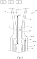
- Fig. 1 schematically shows an interrupter unit 10 for a gas-insulated high or medium voltage device, according to a preferred embodiment.
- the interrupter unit 10 comprises a first arcing contact 12 and a second arcing contact 14.
- the first arcing contact 12 has the form of a plug contact 12 and the second arcing contact 14 is configured as tulip contact 14.
- the plug contact 12 is axially movable along a switching axis 16.
- the tulip contact 14 is also axially movable along the switching axis 16 and is further configured to engage around a proximal portion of the plug contact 12, in the closed position of the contacts 12, 14 (not shown in figure 1 ).
- a distance 18 between the plug contact 12 and tulip contact 14 increases until a final distance 18 is reached.
- Figure 1 shows the interrupter unit 10 during the opening operation
- figure 2 shows the interrupter unit 10 when the final distance 18 between the first and second arcing contacts 12,14 is reached.
- the interrupter unit 10 further comprises an electromagnetic drive 20 (only schematically shown) for driving the axial motion of the first arcing contact 12, i.e. the plug contact, along the switching axis 16 based on a control signal and further comprises a control unit 22 for determining the control signal.
- the control unit 22 is communicationally connected to the electromagnetic drive 20 and configured to send the control signal to the electromagnetic drive 20.
- the interrupter unit 10 further comprises a sensing device 24 communicationally connected to the control unit 22, wherein the sensing device 24 is configured to generate a fault current signal based on analysis of a fault current and to send the fault current signal to the control unit 22.
- the interrupter unit 10 is free of a gear linkage mechanism connecting the motion of the first arcing contact 12 to the motion of the second arcing contact 14.
- the motion of the second arcing contact 14 is affected by another drive (not shown in figure 1 ), in this embodiment a spring drive.
- the interrupter unit 10 comprises a nozzle system 26 wherein the nozzle system 26 at least partially encloses the second contact 14.
- the nozzle system 26 comprises a heating channel 28 for guiding an arc extinguishing gas in a flow-guiding direction 30 from a pressurization chamber to an arcing region 32 for extinguishing an arc formed in the arcing region 32 between the first arcing contact 12 and the second arcing contact 14 during the opening operation of the arcing contacts 12,14.
- the nozzle system 26 comprises an auxiliary nozzle 34 and an insulating nozzle 36 arranged around the auxiliary nozzle 34 and the heating channel 28 is formed in between the insulating nozzle 36 and the auxiliary nozzle 34.
- the insulating nozzle 36 comprises a throat region 38 and adjacent to the throat region 38 a diverging region 40, wherein the throat region 38 forms a cylindrically shaped throat channel and the diverging region 40 forms a diverging channel.
- a tip 42 of the plug contact 12 first moves through the cylindrically shaped throat channel and afterwards through the diverging channel until the final distance 18 between the two arcing contacts 12, 14 is reached.
- the interrupter unit 10 comprises the control unit 22 for determining the control signal.
- the control unit 22 is configured to perform a method for determining the control signal.
- the method for determining the control signal of the electromagnetic drive 20 of the interrupter unit 10 is described.
- figure 3 three diagrams show each the relative position 44 of the first arcing contact 12 and the relative position 46 of the second arcing contact 14 during the opening operation, in relation to their original closed position.
- the diagrams further show the corresponding distance 18 between the first 12 and second arcing contact 14 during the opening operation and also the fault current 48 - i.e. an alternating short circuit current 48.
- the x-axis 50 of figure 3 is a time axis.
- the control unit 22 receives the fault current signal from the sensing device 24.
- the sensing device 24 has generated the fault current signal by analyzing the alternating short circuit current 48 and has sent the fault current signal to the control unit 22.
- the control unit 22 determines the control signal of the electromagnetic drive 20 such that in a second timeframe 52 that occurs during opening operation and before the final distance 18 between the first and second arcing contact 12,14 is reached, the distance 18 between the first and the second arcing contact 12,14 is kept constant ⁇ 20 %.
- the alternating short circuit current 48 has a different value at the beginning of each diagram.
- a duration 54 of the time during which the arc is burning is different for each of the diagrams 3a), 3b) and 3c).
- Figure 3c shows the situation where the arc is extinguished at the minimum arcing time 56 the interrupter unit 10 can reach.
- Figure 3a shows the situation where the arc is extinguished at the maximum arcing time 57, while figure 3b ) shows an intermediate situation.
- the control signal is determined such that the second timeframe 52 starts at the minimum arcing time 56 of the interrupter unit 10.
- the minimum arcing time 56 the interrupter unit 10 can reach, is influenced by the geometry of the interrupter unit 10.
- the control signal is determined such that the second timeframe 52 starts when the distance 18 between the first and second arcing contacts 12,14 is such that an insulating nozzle outflow limiting area 60 defined by the cross-section area of the contours of the diverging channel and the contour of the tip 42 of the plug contact 12 within the diverging channel is equal to or exceeds - and preferably exceeds by maximally 30% - a cross-section area 58 of the cylindrically shaped throat channel in the throat region 38.
- figure 1 shows the interrupter unit 10 in a situation when the second timeframe 52 starts.
- control unit 22 is configured to determine the control signal, such that in the second timeframe 52 of the opening operation the motion of the first arcing contact 12 is essentially matched to the motion of the second arcing contact 14.
- figure 1 also shows the interrupter unit 10 in a situation when the second timeframe 52 stops.
- the control signal is determined such that the distance 18 between the first and second arcing contacts 12,14 in the second timeframe 52 does not correspond to the final distance 18 between the arcing contacts 12,14. Instead, the control signal is determined such that in a first timeframe 62 of the opening operation, wherein the first timeframe 62 immediately precedes the second timeframe 52 the distance 18 between the first and second arcing contacts 12,14 increases, and in a third timeframe 64 of the opening operation, wherein the third timeframe 64 immediately follows the second timeframe 52 the distance between the first arcing contact 12 and the second arcing contact 14 increases until the final distance 18 between the first arcing contact 12 and the second arcing contact 14 is achieved.
- control signal is determined such that the second timeframe 52 lasts until arc extinction of the longest arcing time 57 of the interrupter unit 10.
- Fig. 4 schematically shows a diagram describing the relative positions 44, 46 of the first and second arcing contacts 12,14, and the corresponding distance 18 between the first and second arcing contacts 12,14 during the opening operation according to a further embodiment of the invention.
- control unit 22 is configured to determine the control signal of the electromagnetic drive 20 such that in the second timeframe 52 of the opening operation the first arcing contact 12 and the second arcing contact 14 have no absolute motion.
- the electromagnetic drive 20 is not connected to the plug contact 12 as shown in figure 1 and 2 but to the tulip contact 14.
- Figure 5 schematically shows in the upper half the flow streamlines 66 for a low current duty at current zero for the opening operation shown in figure 3 for the interrupter unit 10 of figures 1 and 2 .
- the interrupter unit 10 is configured as self-blast circuit breaker.
- the shaded area 68,68' in figure 5 indicates the regions of recirculating flow that are established in front of the plug contacts 12,12'.
- the arc extinguishing gas trapped in these fluid pockets is hotter than the arc extinguishing gas flowing outside of the regions 68,68'.
- the region of recirculating flow 68 68' is smaller for the interrupter unit 10 according to the preferred embodiment of the invention compared to the interrupter unit 10' according to prior art. This is because the arc extinguishing gas is accelerated by the smaller cross-sectional area 60 delimited by the plug tip 42 and the divergent contour of the diverging region 40 of the insulating nozzle 36. Reducing the size of the hot gas pocked 68 in front of the plug contact 12 results in a higher dielectric withstand capability of the interrupter unit 10, thus leading to an increase in the interruption performance of the interrupter unit 10.
Landscapes
- Arc-Extinguishing Devices That Are Switches (AREA)
Abstract
determining the control signal of the electromagnetic drive (20) such that in a second timeframe (52) that occurs during opening operation and before the final distance between the first and second arcing contact (12,14) is reached, a distance (18) between the first and the second arcing contact (12,14) is kept constant ± 20 %.
Description
- The invention relates to a computer implemented method for determining a control signal of an electromagnetic drive of an interrupter unit for a high or medium voltage device.
- The present invention also relates to a control unit for determining a control signal of an electromagnetic drive for an interrupter unit of a high or medium voltage device, wherein the control unit is configured to perform the above method.
- The present invention further relates to an interrupter unit for a gas-insulated high or medium voltage device comprising the above control unit.
- Furthermore, the present invention relates to a gas-insulated high or medium voltage device comprising the above interrupter unit.
- High or medium voltage devices, such as circuit breakers and switchgears are essential for the protection of technical equipment, especially in the high voltage range. For example, circuit breakers are predominantly used for interrupting a current, when an electrical fault occurs. As an example, circuit breakers have the task of opening arcing contacts, quench an arc, and keeping the arcing contacts apart from one another in order to avoid a current flow even in case of high electrical potential originating from the electrical fault itself. Circuit breakers may break medium to high short circuit currents of typically 1 kA to 80 kA at medium to high voltages of 12 kV to 72 kV and up to 1200 kV. Thus, high or medium voltage devices accommodate high-voltage conductors such as conductors to which a high voltage is applied.
- Some high or medium voltage devices, namely gas-insulated high or medium voltage devices comprise an insulation gas, for example SF6, in order to shield and insulate the high-voltage conductor from other component and/or to improve quenching of an arc, when operating arcing contacts. In particular the insulation gas is used for extinguishing the arc generated in an arcing region between the arcing contacts when a current is interrupted and is thus also called arc extinguishing gas.
- An electric arc is made up by a flux of electrons and a flux of ions which circulate in opposite directions between the arcing contacts. When the temperature of the arc decreases, ions and electrons recombine and the arc extinguishing gas resumes its isolating properties. In a gas insulated circuit breaker, a gaseous mantle surrounds a core of the arc. The temperature of the gaseous mantle decreases as the distance from the arc axis is increased. The current flow is interrupted when an efficient blast of arc extinguishing gas is applied to cool the arc and extinguish it. The capability of how efficient the arc is extinguished at the zero crossing of the alternating fault current by a high or medium voltage device is called thermal interruption performance.
- The post-arc phase has a critical role in the current interruption process, since during this phase the dielectric strength of the arc extinguishing gas has to be recovered. The hot gas generated from the arc discharge in the interruption process depletes the dielectric recovery strength between the arcing contacts and can potentially lead to re-ignition of the arc after current-zero when the transient recovery voltage rises between the arcing contacts. In other words, even though the thermal interruption has been successfully accomplished, a dielectric breakdown might occur leading to re-ignition and causing the fault-current to flow to the load again. The capability of how efficient re-ignition is prevented by a high or medium voltage device is called dielectric recovery performance.
- A performance problem of gas-insulated high or medium voltage devices is that the thermal interruption performance and the dielectric recovery performance of the gas-insulated high or medium voltage device varies for different interruption duties of the high or medium voltage device.
- It is an object of the invention to provide means to improve the interruption performance of a gas-insulated high or medium voltage device and in particular to improve the thermal interruption performance and/or the dielectric recovery performance of the gas-insulated high or medium voltage device.
- The object of the invention is solved by the features of the independent claims. Modified embodiments are detailed in the dependent claims.
- Thus, the object is solved by a computer implemented method for determining a control signal of an electromagnetic drive of an interrupter unit for a high or medium voltage device, wherein the interrupter unit comprises a first arcing contact and a second arcing contact, wherein for an opening operation of the interrupter unit at least one of the arcing contacts is axially movable along a switching axis thereby bringing the first arcing contact and second arcing contact from a closed position with direct contact between the first and second arcing contacts into an open position with a final distance between the first and second arcing contacts, wherein the interrupter unit comprises at least one electromagnetic drive for driving the axial motion of the first and/or second arcing contact from the closed position to the open position based on the control signal, comprising the step of
- determining the control signal of the electromagnetic drive such that in a second timeframe that occurs during opening operation and before the final distance between the first and second arcing contact is reached, a distance between the first and the second arcing contact is kept constant ± 20 %.
- Furthermore, the object is solved by a control unit for determining a control signal of an electromagnetic drive of an interrupter unit for a high or medium voltage device, wherein the control unit is configured to perform the above method.
- The object is also solved by an interrupter unit for a gas-insulated high or medium voltage device comprising a first arcing contact and a second arcing contact, wherein for an opening operation of the interrupter unit at least one of the arcing contacts is axially movable along a switching axis thereby bringing the first arcing contact and second arcing contact from a closed position with direct contact between the first and second arcing contact into an open position with a final distance between the first and second arcing contact, wherein the interrupter unit comprises at least one electromagnetic drive for driving the axial motion of the first and/or second arcing contact from the closed position to the open position based on a control signal, and wherein the interrupter unit comprises the above control unit.
- Furthermore, the object is also solved by a gas-insulated high or medium voltage device comprising the above interrupter unit, and wherein the high or medium voltage device comprises an arc extinguishing gas.
- One aspect of the invention is, that the motion of the first and/or second arcing contact from the closed position to the open position is in a certain timeframe - which is called second timeframe and occurs during the opening operation - such that the distance between the arcing contacts is essentially constant. It has been observed that the dielectric recovery performance and the thermal interruption performance of high or medium voltage devices are dependent on a duration of a timeframe during which the arc is burning - also called arcing time. It was found that a motion of the arcing contacts by which the distance between the arcing contact is essentially kept constant in the second timeframe improves dielectric recovery performance and thermal interruption performance of the high or medium voltage device.
- In order to provide the axial motion, the interrupter unit comprises at least one electromagnetic drive for driving the axial motion of the first and/or second arcing contact from the closed position to the open position based on the control signal, and further comprises the control unit that is configured to perform the method for determining the control signal. The electromagnetic drive is preferably configured such that a stroke of the electromagnetic drive is controlled by the control signal. In other words, the electromagnetic drive is a programmable electromagnetic drive providing a stroke characteristic based on the control signal. Further preferably the control signal is a digital signal that can be processed by the control unit.
- In other words, the axial motion of the first and/or second arcing contact from the closed to the open position preferably comprises a second timeframe in which the distance between the first and the second arcing contact is essentially kept constant. Being essentially kept constant means that the distance between the first arcing contact and the second arcing contact does only vary for ± 20 % of a predefined distance in the second timeframe.
- It was observed that the interruption performance of the high or medium voltage device depends on the relative position of the first or second arcing contact with respect to an insulating nozzle. At the zero crossing of the alternating short circuit current, also called current-zero - which is the timepoint when the arc is extinguished - one of the arcing contacts is typically located somewhere in a diverging region of the insulating nozzle. It was found that the arc extinguishing gas conditions in the region in front of this arcing contact generally gets worse for current interruption when the position of the arcing contact moves farther into the diverging region of the insulating nozzle. Hence, by keeping the distance between the first and second arcing contacts essentially constant in the second timeframe, the arcing contact is hindered to move farther into the diverging region. Thus, also for long arcing times good interruption conditions are provided.
- Furthermore, the control signal of the electromagnetic drive is determined such that the distance between the first and second arcing contacts in the second timeframe does not correspond to the final distance. In other words, the distance between the first and second arcing contact in the second timeframe is not the final distance, but a distance shorter than the final distance. This preferably also means that the second timeframe is not at the end of the opening operation. Further preferably the final distance between the arcing contacts corresponds to a distance between the first and second arcing contacts that is required by the open gap withstand insulation requirement of the interrupter unit.
- According to a preferred embodiment of the invention the step of determining the control signal of the electromagnetic drive comprises determining the control signal such that in a first timeframe of the opening operation, wherein the first timeframe immediately precedes the second timeframe, the distance between the first and second arcing contacts increases, and in a third timeframe of the opening operation, wherein the third timeframe immediately follows the second timeframe, the distance between the first arcing contact and the second arcing contact increases until the final distance between the first arcing contact and the second arcing contact is achieved. In other words, it is preferred if the opening operation comprises three consecutive timeframes, wherein in the first timeframe the distance between the first and second arcing contact increases, and preferably continuously increases, in the second timeframe the distance is essentially kept constant, and in the third timeframe the distance again increases, and preferably continuously increases, until the final distance is achieved.
- According to another preferred embodiment of the invention the step of determining the control signal of the electromagnetic drive comprises determining the control signal of the electromagnetic drive, such that in the second timeframe of the opening operation the first arcing contact and the second arcing contact have no motion, or such that in the second timeframe of the opening operation the motion of the first arcing contact is essentially matched to the motion of the second arcing contact. Having no motion means in the context of this application that the first and the second arcing contact have no absolute motion.
- In other words, the essentially constant distance between the first and second arcing contacts in the second timeframe can be achieved by two variants:
In the first variant neither the first nor the second arcing contact have an absolute motion during the second timeframe. This is particular preferred for interrupter units where only one arcing contact is axially movable and the other arcing contact is stationary. Circuit breakers having such interrupter units are called single-motion circuit breakers. Furthermore, the first variant is also preferred for interrupter units, where the electromagnetic drive drives the axial motion of the first or second arcing contact and the motion is transferred to the other arcing contact by a gear linkage mechanism. - In the second variant, the motion of one of the arcing contacts is essentially matched to the motion of the other arcing contact in the second timeframe, such that the distance between the arcing contacts is kept constant ± 20 %. As in the first timeframe and in the third timeframe - i.e. the timeframes that precede and follow the second timeframe - the distance between the arcing contact preferably increases, this also preferably means for interrupter units where both arcing contacts perform a motion during opening operation, that in this variant the motion of the first or the second arcing contact preferably comprises an inversion of the motion direction.
- In order to improve the interruption capabilities of the interrupter unit it is beneficial to get cooler and denser arc extinguishing gas in the region around the arcing contact that is located somewhere in a diverging region of the insulating nozzle at current-zero. In relation to this and according to another preferred embodiment of the invention, the interrupter unit comprises an insulating nozzle, wherein the insulating nozzle comprises a throat region and adjacent to the throat region a diverging region, wherein the throat region forms a cylindrically shaped throat channel and the diverging region forms a diverging channel, wherein during opening operation a tip of one arcing contact first moves through the cylindrically shaped throat channel and afterwards through the diverging channel, and wherein the step of determining the control signal of the electromagnetic drive comprises determining the control signal such that the second timeframe starts when the distance between the first and second arcing contacts is such that an insulating nozzle outflow limiting area defined by the minimum cross-section area between the diverging channel and the tip of the one arcing contact lying within the diverging channel is essentially equal to a minimum cross-section area of the cylindrically shaped throat channel. Being essentially equal preferably means that the outflow limiting area in the insulating nozzle divergent is equal to or exceeds the minimum cross-section area of the cylindrically shaped throat channel, and preferably exceeds the minimum cross-section area of the throat channel by maximally 30 %.
- Preferably, the one arcing contact that moves through the cylindrically shaped throat channel and the diverging channel during opening operation is the plug contact. In other words, the position of the first and second arcing contacts with respect to each other, at which the second timeframe starts, is preferably a position where the arc extinguishing gas has beneficial flow conditions, and more preferably where the annular shaped cross-section area defined by the contours of the tip of the plug contact and the contours of the diverging channel of the insulating nozzle equals or exceeds, and preferably exceeds by maximally 30 %, the circular shaped cross-section area defined by the contours of the cylindrically shaped throat channel of the throat region. These conditions typically define the minimum arcing time of the interrupter unit. Hence, and according to another preferred embodiment of the invention, the step of determining the control signal of the electromagnetic drive comprises determining the control signal such that the second timeframe starts at the minimum arcing time of the interrupter unit.
- According to another preferred embodiment of the invention, the step of determining the control signal of the electromagnetic drive comprises determining the control signal such that the second timeframe lasts until arc extinction of a longest arcing time of the interrupter unit. Preferably as arc extinction happens at current-zero, the arc extinction of the longest arcing time of the interrupter unit is defined by the minimum arcing time of the interrupter unit and the frequency of the alternating fault current. Further preferably the distance between the first and second arcing contacts in the third timeframe increased rapidly to attain the final distance required by open gap insulation tests, such as lightning impulse, and/or dielectric integrity.
- Further preferably, the method comprises the step of receiving a fault current signal, and wherein the step of determining the control signal of the electromagnetic drive comprises determining the control signal of the electromagnetic drive taking the received fault current signal and the type of interrupter unit into account, such that
- in cases where the interrupter unit is a puffer-type interrupter unit and the fault current signal is a capacitive current switching or a short-line fault duty, the distance between the first and the second arcing contacts in the second timeframe is essentially kept constant, and/or
- in cases where the interrupter unit is a self-blast interrupter unit and the fault current signal is a low current duty, the distance between the first and the second arcing contacts in the second timeframe is essentially kept constant, and/or
- in cases where the interrupter unit is a self-blast interrupter unit and the fault current signal is a high current duty, the distance between the first and the second arcing contacts in the second timeframe is essentially kept constant or increases.
- Further preferably the fault current signal is a digital signal that can be processed by the control unit. It was found that keeping the distance between the first and second arcing contact in the second timeframe essentially constant increases the performance of puffer-type interrupter unit for, for example, capacitive current switching and for short-line fault duties. Furthermore, also the dielectric recovery performance of self-blast interrupter units for low current duties can be significantly increased by keeping the distance between the first and second arcing contact essentially constant in the second timeframe. Furthermore, in cases where the interrupter unit is a self-blast interrupter unit and the fault current signal is a high current duty, it was found that keeping the distance between the first and second arcing contact in the second timeframe essentially constant does not negatively affect the interruption performance with respect to a movement of the arcing contacts, where the distance in the second timeframe increases.
- Other aspects and advantages of the method for determining the control signal of the electromagnetic drive of the interrupter unit for a high or medium voltage device are directly and unambiguously derived by the person skilled in the art from the description of the interrupter unit, the description of the gas-insulated high or medium voltage device and the figure description.
- As already mentioned, the invention is also directed to the control unit configured to perform the above described method and also to the interrupter unit for a gas-insulated high or medium voltage device comprising the first arcing contact and the second arcing contact, wherein for the opening operation of the interrupter unit at least one of the arcing contacts is axially movable along a switching axis thereby bringing the first arcing contact and second arcing contact from the closed position with direct contact between the first and second arcing contacts into the open position with a final distance between the first and second arcing contacts, wherein the interrupter unit comprises the at least one electromagnetic drive for driving the axial motion of the first and/or second arcing contact from the closed position to the open position based on the control signal, and wherein the interrupter unit comprises the control unit.
- As the motion of the arcing contact of the interrupter unit are such that in the second timeframe that occurs during opening operation and before the final distance between the first and second arcing contact is reached, the distance between the first and the second arcing contact is essentially kept constant, beneficial arc extinguishing gas conditions can be achieved during the opening operation and thus the performance of the interrupter unit is enhanced.
- According to a preferred embodiment of the invention the interrupter unit comprises a sensing device communicationally connected to the control unit, and wherein the sensing device is configured to generate a fault current signal based on analysis of a fault current and to send the fault current signal to the control unit. This is an easy way to ensure that the motion of the first and/or second arcing contact is adapted to the fault current signal. In other words, the control unit is preferably coupled to the sensing devices in order to produce a control signal for a motion of the first and/or second arcing contact that is adapted to different duties of the interrupter unit. By customizing the travel curves of the first and/or second arcing contact, the electromagnetic drive provides the specific stroke characteristics, allowing an optimal interruption performance for diverse interruption duties. Furthermore, the sensing device preferably performs an analysis of the fault current and, based on it, will send the fault current signal to the control unit, which than proposes the motion law for the interruption duties for which it is beneficial.
- According to another preferred embodiment of the invention, the interrupter unit is configured such that for the opening operation only the first or second arcing contact is axially movable along the switching axis, wherein the electromagnetic drive drives the axial motion of the axially movable arcing contact based on the control signal, and wherein the control unit is configured to determine the control signal, such that in the second timeframe of the opening operation the first arcing contact and the second arcing contact have no motion. In other words, in this embodiment the interrupter unit is configured as a single motion interruption unit, where one arcing contact is stationary during the opening operation. In this case in the second timeframe of the opening operation the first arcing contact and the second arcing contact have no absolute motion.
- According to an alternative embodiment of the invention, the interrupter unit is configured such that for the opening operation of the interrupter unit the first and second arcing contacts are axially movable along the switching axis, wherein the electromagnetic drive is connected to the first or second arcing contact and drives the axial motion of said driving arcing contact based on the control signal, wherein the interrupter unit comprises a gear linkage mechanism connecting the motion of said driving arcing contact to the motion of the other indirectly driven arcing contact, and wherein the control unit is configured to determine the control signal, such that in the second timeframe of the opening operation the first arcing contact and the second arcing contact have no motion. In other words, in this embodiment one of the arcing contacts, i.e. the driving arcing contact, is directly connected to the electromagnetic drive, while the other arcing contact, i.e. the driven arcing contact, is indirectly driven via a gear linkage mechanism by the driving arcing contact.
- According to a further alternative embodiment of the invention the interrupter unit is free of a gear linkage mechanism connecting the motion of one of the arcing contacts to the motion of the other arcing contact, wherein the electromagnetic drive drives the axial motion of the first and/or second arcing contact based on the control signal, and wherein the control unit is configured to determine the control signal, such that in the second timeframe of the opening operation the motion of the first arcing contact is essentially matched to the motion of the second arcing contact. In this preferred embodiment the interrupter unit is free of a gear linkage mechanism, which makes the structure of the interrupter unit less complex. Furthermore, the control signal can be a control signal dedicated for the motion of only one of the arcing contacts or it can be a control signal dedicated for the motion of both arcing contacts.
- According to another alternative and particular preferred embodiment of the invention the interrupter unit is configured such that for the opening operation of the interrupter unit the first and second arcing contacts are axially movable along the switching axis, wherein the electromagnetic drive is connected to the first or second arcing contact and drives the axial motion of said arcing contact based on the control signal, wherein the interrupter unit is free of a gear linkage mechanism connecting the motion of said arcing contact to the motion of the other arcing contact, and wherein the control unit is configured to determine the control signal, such that in the second timeframe of the opening operation the motion of said arcing contact is essentially matched to the motion of the other arcing contact. In this embodiment the motion of the arcing contact not driven by the electromagnetic drive is preferably driven by a conventional drive such as a spring drive or a hydraulic drive. In particular the conventional drive preferably provides a physically predetermined stroke characteristic and is not programmable.
- In connection to the above and according to another preferred embodiment of the invention the interrupter unit is configured such that for the opening operation of the interrupter unit the first and second arcing contacts are axially movable along the switching axis, wherein the interrupter unit is free of a gear linkage mechanism connecting the motion of one of the arcing contacts to the motion of the other arcing contact, wherein the electromagnetic drive drives the axial motion of the first arcing contact based on the control signal, wherein the interrupter unit comprises a drive for driving the motion of the second arcing contact, wherein the motion of the second arcing contact effects a pressurization of a pressurization chamber, and wherein the control unit is configured to determine the control signal, such that in the second timeframe of the opening operation the motion of the first arcing contact is essentially matched to the motion of the second arcing contact. The drive that effects the motion of the second arcing contact and the pressurization of the pressurization chamber is preferably not a programmable drive, but a driven that provides a physically predetermined stroke characteristic such as a spring drive or a hydraulic drive.
- According to another preferred embodiment of the invention the interrupter unit is configured such that for the opening operation of the interrupter unit the first and second arcing contacts are axially movable along the switching axis, wherein the interrupter unit comprises two electromagnetic drives, each connected to one of the arcing contacts for driving the axial motion of the arcing contacts based on the control signal, wherein the interrupter unit is free of a gear linkage mechanism connecting the motion of one of the arcing contacts to the motion of the other arcing contact, and wherein the control unit is configured to determine the control signal, such that in the second timeframe of the opening operation the first arcing contact and the second arcing contact have no motion, or such that in the second timeframe of the opening operation the motion of one arcing contact is essentially matched to the motion of the other arcing contact. In this particular embodiment the control signal is a signal dedicated for two electromagnetic drives.
- As already mentioned, the invention also relates to a gas-insulated high or medium voltage device comprising the above-described interrupter unit, and wherein the high or medium voltage device comprises the arc extinguishing gas.
- Preferably the arc extinguishing gas is selected from CO2, SF6, mixtures of CO2 or SF6 with a carrier gas and/or mixtures of fluoroketons and/or fluoronitriles with a carrier gas. The carrier gas for use with fluoroketons and/or fluoronitriles and/or SF6 may comprise air, N2, CO2, and mixtures thereof. Further preferably the arc extinguishing gas may have a reduced fluorine content compared to SF6, or may even be essentially fluorine free.
- According to another preferred embodiment of the invention the gas-insulated high or medium voltage device is preferably a circuit breaker and more preferably the gas-insulated high or medium voltage device is configured as a puffer-type circuit breaker or a self-blast circuit breaker. Furthermore, in the context of this invention medium to high voltages means voltages of 12 kV to 72 kV (medium voltage) and up to 1200 kV (high voltage).
- These and other aspects of the invention will be apparent from and elucidated with reference to the embodiments described hereinafter.
- In the drawings:
- Fig. 1
- schematically shows an interrupter unit of a high or medium voltage device according to a preferred embodiment of the invention,
- Fig. 2
- schematically shows the interrupter unit of
figure 1 , when a final distance between a first and second arcing contact is reached, - Fig. 3
- schematically shows in a) b) and c) each a diagram describing the relative position of a first and second arcing contact, and the corresponding distance between the first and second arcing contact during an opening operation of the interrupter unit of
figure 1 , - Fig. 4
- schematically shows a diagram describing the relative position of a first and second arcing contact, and the corresponding distance between the first and second arcing contact during an opening operation according to a further embodiment of the invention,
- Fig. 5
- schematically shows in the upper half flow streamlines for a low current duty at current zero for the opening operation shown in
figure 3 for the interrupter unit offigures 1 and2 , and in the lower half flow streamlines for a low current duty at current zero for an opening operation of an interrupter unit according to prior art. -
Fig. 1 schematically shows aninterrupter unit 10 for a gas-insulated high or medium voltage device, according to a preferred embodiment. Theinterrupter unit 10 comprises afirst arcing contact 12 and asecond arcing contact 14. In this embodiment thefirst arcing contact 12 has the form of aplug contact 12 and thesecond arcing contact 14 is configured astulip contact 14. Theplug contact 12 is axially movable along a switchingaxis 16. Thetulip contact 14 is also axially movable along the switchingaxis 16 and is further configured to engage around a proximal portion of theplug contact 12, in the closed position of thecontacts 12, 14 (not shown infigure 1 ). During opening operation of theinterrupter unit 10, adistance 18 between theplug contact 12 andtulip contact 14 increases until afinal distance 18 is reached. -
Figure 1 shows theinterrupter unit 10 during the opening operation, whilefigure 2 shows theinterrupter unit 10 when thefinal distance 18 between the first andsecond arcing contacts - The
interrupter unit 10 further comprises an electromagnetic drive 20 (only schematically shown) for driving the axial motion of thefirst arcing contact 12, i.e. the plug contact, along the switchingaxis 16 based on a control signal and further comprises acontrol unit 22 for determining the control signal. Thecontrol unit 22 is communicationally connected to theelectromagnetic drive 20 and configured to send the control signal to theelectromagnetic drive 20. In this embodiment theinterrupter unit 10 further comprises asensing device 24 communicationally connected to thecontrol unit 22, wherein thesensing device 24 is configured to generate a fault current signal based on analysis of a fault current and to send the fault current signal to thecontrol unit 22. - Furthermore, in this embodiment the
interrupter unit 10 is free of a gear linkage mechanism connecting the motion of thefirst arcing contact 12 to the motion of thesecond arcing contact 14. Instead, the motion of thesecond arcing contact 14 is affected by another drive (not shown infigure 1 ), in this embodiment a spring drive. - As can also be seen in
figure 1 , theinterrupter unit 10 comprises a nozzle system 26 wherein the nozzle system 26 at least partially encloses thesecond contact 14. The nozzle system 26 comprises aheating channel 28 for guiding an arc extinguishing gas in a flow-guidingdirection 30 from a pressurization chamber to an arcingregion 32 for extinguishing an arc formed in the arcingregion 32 between thefirst arcing contact 12 and thesecond arcing contact 14 during the opening operation of the arcingcontacts - In this embodiment the nozzle system 26 comprises an auxiliary nozzle 34 and an insulating nozzle 36 arranged around the auxiliary nozzle 34 and the
heating channel 28 is formed in between the insulating nozzle 36 and the auxiliary nozzle 34. - The insulating nozzle 36 comprises a
throat region 38 and adjacent to the throat region 38 a divergingregion 40, wherein thethroat region 38 forms a cylindrically shaped throat channel and the divergingregion 40 forms a diverging channel. During opening operation, atip 42 of theplug contact 12 first moves through the cylindrically shaped throat channel and afterwards through the diverging channel until thefinal distance 18 between the two arcingcontacts - As already mentioned, the
interrupter unit 10 comprises thecontrol unit 22 for determining the control signal. For this thecontrol unit 22 is configured to perform a method for determining the control signal. In the following, and also with reference tofigures 1 to 3 , the method for determining the control signal of theelectromagnetic drive 20 of theinterrupter unit 10 is described. - In
figure 3 three diagrams show each therelative position 44 of thefirst arcing contact 12 and therelative position 46 of thesecond arcing contact 14 during the opening operation, in relation to their original closed position. The diagrams further show thecorresponding distance 18 between the first 12 andsecond arcing contact 14 during the opening operation and also the fault current 48 - i.e. an alternating short circuit current 48. Thex-axis 50 offigure 3 is a time axis. - In a first step of the method the
control unit 22 receives the fault current signal from thesensing device 24. Thesensing device 24 has generated the fault current signal by analyzing the alternating short circuit current 48 and has sent the fault current signal to thecontrol unit 22. In a subsequent step, thecontrol unit 22 determines the control signal of theelectromagnetic drive 20 such that in asecond timeframe 52 that occurs during opening operation and before thefinal distance 18 between the first andsecond arcing contact distance 18 between the first and thesecond arcing contact - As can be seen by comparing
figures 3a) 3b) and 3c ), the alternating short circuit current 48 has a different value at the beginning of each diagram. Hence, also aduration 54 of the time during which the arc is burning, is different for each of the diagrams 3a), 3b) and 3c). -
Figure 3c ) shows the situation where the arc is extinguished at theminimum arcing time 56 theinterrupter unit 10 can reach.Figure 3a ) shows the situation where the arc is extinguished at themaximum arcing time 57, whilefigure 3b ) shows an intermediate situation. - As can be seen in
figures 3a) to 3c ) the control signal is determined such that thesecond timeframe 52 starts at theminimum arcing time 56 of theinterrupter unit 10. Theminimum arcing time 56 theinterrupter unit 10 can reach, is influenced by the geometry of theinterrupter unit 10. With reference tofigure 1 the control signal is determined such that thesecond timeframe 52 starts when thedistance 18 between the first andsecond arcing contacts outflow limiting area 60 defined by the cross-section area of the contours of the diverging channel and the contour of thetip 42 of theplug contact 12 within the diverging channel is equal to or exceeds - and preferably exceeds by maximally 30% - across-section area 58 of the cylindrically shaped throat channel in thethroat region 38. In other words,figure 1 shows theinterrupter unit 10 in a situation when thesecond timeframe 52 starts. - As can be seen from
figure 3 , thecontrol unit 22 is configured to determine the control signal, such that in thesecond timeframe 52 of the opening operation the motion of thefirst arcing contact 12 is essentially matched to the motion of thesecond arcing contact 14. Hencefigure 1 also shows theinterrupter unit 10 in a situation when thesecond timeframe 52 stops. - Furthermore, as can also be seen in
figure 3 , the control signal is determined such that thedistance 18 between the first andsecond arcing contacts second timeframe 52 does not correspond to thefinal distance 18 between the arcingcontacts first timeframe 62 of the opening operation, wherein thefirst timeframe 62 immediately precedes thesecond timeframe 52 thedistance 18 between the first andsecond arcing contacts third timeframe 64 of the opening operation, wherein thethird timeframe 64 immediately follows thesecond timeframe 52 the distance between thefirst arcing contact 12 and thesecond arcing contact 14 increases until thefinal distance 18 between thefirst arcing contact 12 and thesecond arcing contact 14 is achieved. - Furthermore, as can also be seen from
figure 3 , the control signal is determined such that thesecond timeframe 52 lasts until arc extinction of thelongest arcing time 57 of theinterrupter unit 10. -
Fig. 4 schematically shows a diagram describing therelative positions second arcing contacts corresponding distance 18 between the first andsecond arcing contacts - In this embodiment, the
control unit 22 is configured to determine the control signal of theelectromagnetic drive 20 such that in thesecond timeframe 52 of the opening operation thefirst arcing contact 12 and thesecond arcing contact 14 have no absolute motion. In this embodiment theelectromagnetic drive 20 is not connected to theplug contact 12 as shown infigure 1 and2 but to thetulip contact 14. -
Figure 5 schematically shows in the upper half the flow streamlines 66 for a low current duty at current zero for the opening operation shown infigure 3 for theinterrupter unit 10 offigures 1 and2 . Theinterrupter unit 10 is configured as self-blast circuit breaker. - In the lower half of
figure 5 the flow streamlines 66' for a low current duty at current zero for a prior art self-blast circuit breaker interrupter unit 10' is shown. The prior art interrupter unit 10' performs a motion of the arcingcontacts 12' 14' during opening operation where the distance between the first andsecond arcing contacts 12',14' is not constant within the second timeframe, but is continuously increasing. - As both halves of
figure 5 refer to the longest arcing time, the position of theplug contact 12' of the prior art interrupter unit 10' is farther downstream in the diverging region 40' compared to the position of theplug contact 12 for theinterrupter unit 10 according to a preferred embodiment of the invention. - The shaded
area 68,68' infigure 5 indicates the regions of recirculating flow that are established in front of theplug contacts regions 68,68'. - As can be seen in
figure 5 , the region of recirculatingflow 68 68' is smaller for theinterrupter unit 10 according to the preferred embodiment of the invention compared to the interrupter unit 10' according to prior art. This is because the arc extinguishing gas is accelerated by the smallercross-sectional area 60 delimited by theplug tip 42 and the divergent contour of the divergingregion 40 of the insulating nozzle 36. Reducing the size of the hot gas pocked 68 in front of theplug contact 12 results in a higher dielectric withstand capability of theinterrupter unit 10, thus leading to an increase in the interruption performance of theinterrupter unit 10. - While the invention has been illustrated and described in detail in the drawings and foregoing description, such illustration and description are to be considered illustrative or exemplary and not restrictive; the invention is not limited to the disclosed embodiments. Other variations to be disclosed embodiments can be understood and effected by those skilled in the art in practicing the claimed invention, from a study of the drawings, the disclosed, and the appended claims. In the claims, the word "comprising" does not exclude other elements or steps, and the indefinite article "a" or "an" does not exclude a plurality. The mere fact that certain measures are recited in mutually different dependent claims does not indicate that a combination of these measures cannot be used to advantage. Any reference signs in the claims should not be construed as limiting scope.
-
- 10
- interrupter unit
- 12
- first arcing contact, plug contact
- 14
- second arcing contact, tulip contact
- 16
- switching axis
- 18
- distance
- 20
- electromagnetic drive
- 22
- control unit
- 24
- sensing device
- 26
- nozzle system
- 28
- heating channel
- 30
- flow guiding direction
- 32
- arcing region
- 34
- auxiliary nozzle
- 36
- insulating nozzle
- 38
- throat region
- 40
- diverging region
- 42
- plug tip
- 44
- relative position of first arcing contact
- 46
- relative position of second arcing contact
- 48
- fault current
- 50
- x-axis
- 52
- second timeframe
- 54
- duration of arc burning
- 56
- minimum arcing time
- 57
- maximum arcing time, arc extinction of the longest arcing time
- 58
- cross section area of channel in throat region
- 60
- nozzle outflow limiting area
- 62
- first timeframe
- 64
- second timeframe
- 66
- flow streamlines of arc extinguishing gas
- 68
- regions of recirculating flow, hot gas pocket
Claims (15)
- Computer implemented method for determining a control signal of an electromagnetic drive (20) of an interrupter unit (10) for a high or medium voltage device, wherein the interrupter unit (10) comprises a first arcing contact (12) and a second arcing contact (14),wherein for an opening operation of the interrupter unit (10) at least one of the arcing contacts (12,14) is axially movable along a switching axis (16) thereby bringing the first arcing contact (12) and second arcing contact (14) from a closed position with direct contact between the first and second arcing contacts (12,14) into an open position with a final distance between the first and second arcing contacts (12,14),wherein the interrupter unit (10) comprises at least one electromagnetic drive (20) for driving the axial motion of the first and/or second arcing contact (12,14) from the closed position to the open position based on the control signal,comprising the step of- determining the control signal of the electromagnetic drive (20) such that in a second timeframe (52) that occurs during opening operation and before the final distance between the first and second arcing contact (12,14) is reached, a distance (18) between the first and the second arcing contact (12,14) is kept constant ± 20 %.
- The computer implemented method according to any of the previous claims, wherein the step of determining the control signal of the electromagnetic drive (20) comprises determining the control signal such that in a first timeframe (62) of the opening operation, wherein the first timeframe (62) immediately precedes the second timeframe (52), the distance (18) between the first and second arcing contacts (12,14) increases, and in a third timeframe (64) of the opening operation, wherein the third timeframe (64) immediately follows the second timeframe (52), the distance (18) between the first arcing contact (12) and the second arcing contact (14) increases until the final distance between the first arcing contact (12) and the second arcing contact (14) is achieved.
- The computer implemented method according to the previous claim, wherein the step of determining the control signal of the electromagnetic drive (20) comprises determining the control signal of the electromagnetic drive (20) such that in the second timeframe (52) of the opening operation the first arcing contact (12) and the second arcing contact (14) have no motion, or such that in the second timeframe (52) of the opening operation the motion of the first arcing contact (12) is essentially matched to the motion of the second arcing contact (14).
- The computer implemented method according to any of the previous claims, the interrupter unit (10) comprises an insulating nozzle (36), wherein the insulating nozzle (36) comprises a throat region (38) and adjacent to the throat region (38) a diverging region (40), wherein the throat region (38) forms a cylindrically shaped throat channel and the diverging region (40) forms a diverging channel, wherein during opening operation a tip (42) of one arcing contact (12) first moves through the cylindrically shaped throat channel and afterwards through the diverging channel, and wherein the step of determining the control signal of the electromagnetic drive (20) comprises determining the control signal such that the second timeframe (52) starts when the distance (18) between the first and second arcing contacts (12,14) is such that an insulating nozzle outflow limiting area (60) defined by a minimum cross-section area between the diverging channel and the tip (42) of the one arcing contact (12) lying within the diverging channel is equal to or exceeds, and preferably exceeds by maximally 30%, a minimum cross-section area (58) of the cylindrically shaped throat channel, and/or
wherein the step of determining the control signal of the electromagnetic drive (20) comprises determining the control signal such that the second timeframe (52) starts at a minimum arcing time (56) of the interrupter unit (10). - The computer implemented method according to any of the previous claims, wherein the step of determining the control signal of the electromagnetic drive (20) comprises determining the control signal such that the second timeframe (52) lasts until arc extinction of a longest arcing time (57) of the interrupter unit (10).
- Control unit (22) for determining a control signal of an electromagnetic drive (20) of an interrupter unit (10) for a high or medium voltage device, wherein the control unit (22) is configured to perform the method according to any of the previous method claims.
- Interrupter unit (10) for a gas-insulated high or medium voltage device comprisinga first arcing contact (12) and a second arcing contact (14),wherein for an opening operation of the interrupter unit (10) at least one of the arcing contacts (12,14) is axially movable along a switching axis (16) thereby bringing the first arcing contact (12) and second arcing contact (14) from a closed position with direct contact between the first and second arcing contacts (12,14) into an open position with a final distance between the first and second arcing contacts (12,14),wherein the interrupter unit (10) comprises at least one electromagnetic drive (20) for driving the axial motion of the first and/or second arcing contact (12,14) from the closed position to the open position based on a control signal, andwherein the interrupter unit (10) comprises the control unit (22) according to the previous claim.
- The interrupter unit (10) according to the previous interrupter unit claim comprising a sensing device (24) communicationally connected to the control unit (22), and wherein the sensing device (24) is configured to generate a fault current signal based on analysis of a fault current (42) and to send the fault current signal to the control unit (22).
- Interrupter unit (10) according to claim 7 or 8, wherein the interrupter unit (10) is configured such that for the opening operation of the interrupter unit (10) the first and second arcing contacts (12,14) are axially movable along the switching axis (16), wherein the electromagnetic drive (20) is connected to the first or second arcing contact (12,14) and drives the axial motion of said driving arcing contact (12,14) based on the control signal, wherein the interrupter unit (10) comprises a gear linkage mechanism connecting the motion of said driving arcing contact (12,14) to the motion of the other indirectly driven arcing contact (12,14), and wherein the control unit (22) is configured to determine the control signal, such that in the second timeframe (52) of the opening operation the first arcing contact (12) and the second arcing contact (14) have no motion.
- Interrupter unit (10) according to claim 7 or 8, wherein the interrupter unit (10) is free of a gear linkage mechanism connecting the motion of one of the arcing contacts (12,14) to the motion of the other arcing contact (12,14), wherein the electromagnetic drive (20) drives the axial motion of the first and/or second arcing contact (12,14) based on the control signal, and wherein the control unit (22) is configured to determine the control signal, such that in the second timeframe (52) of the opening operation the motion of the first arcing contact (12) is essentially matched to the motion of the second arcing contact (14).
- Interrupter unit (10) according to claim 7 or 8, wherein the interrupter unit (10) is configured such that for the opening operation of the interrupter unit (10) the first and second arcing contacts (12,14) are axially movable along the switching axis (16), wherein the interrupter unit (10) is free of a gear linkage mechanism connecting the motion of one of the arcing contacts (12,14) to the motion of the other arcing contact (12,14), wherein the electromagnetic drive (20) drives the axial motion of the first arcing contact (12) based on the control signal, wherein the interrupter unit (10) comprises a drive for driving the motion of the second arcing contact (14), wherein the motion of the second arcing contact (14) effects a pressurization of a pressurization chamber, and wherein the control unit (22) is configured to determine the control signal, such that in the second timeframe (52) of the opening operation the motion of the first arcing contact (12) is essentially matched to the motion of the second arcing contact (14).
- Interrupter unit (10) according to claim 7 or 8, wherein the interrupter unit (10) is configured such that for the opening operation of the interrupter unit (10) the first and second arcing contacts (12,14) are axially movable along the switching axis (16), wherein the interrupter unit (10) comprises two electromagnetic drives (20), each connected to one of the arcing contacts (12,14) for driving the axial motion of the arcing contacts (12,14) based on the control signal, wherein the interrupter unit (1) is free of a gear linkage mechanism connecting the motion of one of the arcing contacts (12,14) to the motion of the other arcing contact (12,14), and wherein the control unit (22) is configured to determine the control signal, such that in the second timeframe (52) of the opening operation the first arcing contact (12) and the second arcing contact (14) have no motion, or such that in the second timeframe (52) of the opening operation the motion of one arcing contact (12,14) is essentially matched to the motion of the other arcing contact (12,14).
- Gas-insulated high or medium voltage device comprising an interrupter unit (10) according to any of the previous interrupter unit claims, and wherein the high or medium voltage device comprises an arc extinguishing gas.
- Gas-insulated high or medium voltage device according to the previous claim, wherein the gas-insulated high or medium voltage device is configured as a circuit breaker and more preferably as a puffer-type circuit breaker, or a self-blast circuit breaker.
- Gas insulated high or medium voltage device according claim 13 or 14, wherein the arc extinguishing gas is selected from CO2, SF6, mixtures of CO2 or SF6 with a carrier gas and/or mixtures of fluoroketons and/or fluoronitriles with a carrier gas.
Priority Applications (1)
| Application Number | Priority Date | Filing Date | Title |
|---|---|---|---|
| EP22203642.8A EP4362054A1 (en) | 2022-10-25 | 2022-10-25 | Method for determining a control signal of an electromagnetic drive of an interrupter unit, and interrupter unit for a gas-insulated high or medium voltage device |
Applications Claiming Priority (1)
| Application Number | Priority Date | Filing Date | Title |
|---|---|---|---|
| EP22203642.8A EP4362054A1 (en) | 2022-10-25 | 2022-10-25 | Method for determining a control signal of an electromagnetic drive of an interrupter unit, and interrupter unit for a gas-insulated high or medium voltage device |
Publications (1)
| Publication Number | Publication Date |
|---|---|
| EP4362054A1 true EP4362054A1 (en) | 2024-05-01 |
Family
ID=83996124
Family Applications (1)
| Application Number | Title | Priority Date | Filing Date |
|---|---|---|---|
| EP22203642.8A Pending EP4362054A1 (en) | 2022-10-25 | 2022-10-25 | Method for determining a control signal of an electromagnetic drive of an interrupter unit, and interrupter unit for a gas-insulated high or medium voltage device |
Country Status (1)
| Country | Link |
|---|---|
| EP (1) | EP4362054A1 (en) |
Citations (3)
| Publication number | Priority date | Publication date | Assignee | Title |
|---|---|---|---|---|
| WO1995028025A1 (en) * | 1994-04-11 | 1995-10-19 | Abb Power T & D Company Inc. | Intelligent circuit breaker providing synchronous switching and condition monitoring |
| US6023404A (en) * | 1997-06-04 | 2000-02-08 | Gec Alsthom T & D Sa | Method of monitoring and diagnosing the operation of high voltage electrical apparatus |
| WO2015111919A1 (en) * | 2014-01-24 | 2015-07-30 | 일진전기 주식회사 | Switchgear |
-
2022
- 2022-10-25 EP EP22203642.8A patent/EP4362054A1/en active Pending
Patent Citations (3)
| Publication number | Priority date | Publication date | Assignee | Title |
|---|---|---|---|---|
| WO1995028025A1 (en) * | 1994-04-11 | 1995-10-19 | Abb Power T & D Company Inc. | Intelligent circuit breaker providing synchronous switching and condition monitoring |
| US6023404A (en) * | 1997-06-04 | 2000-02-08 | Gec Alsthom T & D Sa | Method of monitoring and diagnosing the operation of high voltage electrical apparatus |
| WO2015111919A1 (en) * | 2014-01-24 | 2015-07-30 | 일진전기 주식회사 | Switchgear |
Similar Documents
| Publication | Publication Date | Title |
|---|---|---|
| US3814883A (en) | Gas-blast circuit interrupter with insulating arc shield | |
| EP3477675B1 (en) | Gas-insulated medium-voltage switch with shield device | |
| US5391930A (en) | Circuit breaker with parallel resistor | |
| US4617435A (en) | Hybrid circuit breaker | |
| US5231256A (en) | Puffer type gas-insulated circuit breaker | |
| CN101589446A (en) | High voltage isolating circuit breaker and method of operation thereof | |
| US8901447B2 (en) | Circuit breaker with parallel rated current paths | |
| EP2369608B1 (en) | High-voltage circuit breaker | |
| CN111630622B (en) | Gas-insulated high-or medium-voltage circuit breaker | |
| EP3561840B1 (en) | Gas-insulation switch device | |
| US11302499B1 (en) | Vacuum circuit breaker | |
| EP4738416A1 (en) | Circuit-breaker | |
| EP4246548A1 (en) | Interrupter unit for gas-insulated high or medium voltage device and gas-insulated high or medium voltage device | |
| EP4383306A1 (en) | Interrupter unit for gas-insulated high or medium voltage device | |
| US20250149276A1 (en) | Switching device with an isolating or earthing function | |
| EP2827353A1 (en) | Electrical switching device | |
| RU2006976C1 (en) | Arc control device of high-voltage gas-filled autocompression switch | |
| EP4117006B1 (en) | Gas-insulated high or medium voltage circuit breaker | |
| EP4227968A1 (en) | Fast earthing switch for interrupting non-short-circuit currents | |
| EP4235723B1 (en) | Three-phase gas-insulated circuit breaker | |
| RU2148281C1 (en) | Arc-control device of self-compression gas-filled high-voltage switch | |
| EP4550379A1 (en) | Circuit-breaker with a nozzle structure | |
| KR101621765B1 (en) | Switch-gear | |
| WO2023152205A1 (en) | High-voltage disconnector switch | |
| JP2523478B2 (en) | Puffer type gas breaker |
Legal Events
| Date | Code | Title | Description |
|---|---|---|---|
| PUAI | Public reference made under article 153(3) epc to a published international application that has entered the european phase |
Free format text: ORIGINAL CODE: 0009012 |
|
| STAA | Information on the status of an ep patent application or granted ep patent |
Free format text: STATUS: THE APPLICATION HAS BEEN PUBLISHED |
|
| AK | Designated contracting states |
Kind code of ref document: A1 Designated state(s): AL AT BE BG CH CY CZ DE DK EE ES FI FR GB GR HR HU IE IS IT LI LT LU LV MC ME MK MT NL NO PL PT RO RS SE SI SK SM TR |
|
| STAA | Information on the status of an ep patent application or granted ep patent |
Free format text: STATUS: REQUEST FOR EXAMINATION WAS MADE |
|
| 17P | Request for examination filed |
Effective date: 20241030 |
|
| RBV | Designated contracting states (corrected) |
Designated state(s): AL AT BE BG CH CY CZ DE DK EE ES FI FR GB GR HR HU IE IS IT LI LT LU LV MC ME MK MT NL NO PL PT RO RS SE SI SK SM TR |
|
| STAA | Information on the status of an ep patent application or granted ep patent |
Free format text: STATUS: EXAMINATION IS IN PROGRESS |
|
| 17Q | First examination report despatched |
Effective date: 20260218 |