EP4361993A1 - Lane guiding device - Google Patents
Lane guiding device Download PDFInfo
- Publication number
- EP4361993A1 EP4361993A1 EP23200339.2A EP23200339A EP4361993A1 EP 4361993 A1 EP4361993 A1 EP 4361993A1 EP 23200339 A EP23200339 A EP 23200339A EP 4361993 A1 EP4361993 A1 EP 4361993A1
- Authority
- EP
- European Patent Office
- Prior art keywords
- lane
- warning
- vehicle
- road
- traveling
- Prior art date
- Legal status (The legal status is an assumption and is not a legal conclusion. Google has not performed a legal analysis and makes no representation as to the accuracy of the status listed.)
- Pending
Links
- 238000011144 upstream manufacturing Methods 0.000 claims description 11
- 238000010586 diagram Methods 0.000 description 12
- 230000000052 comparative effect Effects 0.000 description 7
- 238000000034 method Methods 0.000 description 4
- 238000012986 modification Methods 0.000 description 2
- 230000004048 modification Effects 0.000 description 2
- 230000004397 blinking Effects 0.000 description 1
- 230000009194 climbing Effects 0.000 description 1
- 230000000694 effects Effects 0.000 description 1
Images



Classifications
-
- G—PHYSICS
- G08—SIGNALLING
- G08G—TRAFFIC CONTROL SYSTEMS
- G08G1/00—Traffic control systems for road vehicles
- G08G1/09—Arrangements for giving variable traffic instructions
- G08G1/0962—Arrangements for giving variable traffic instructions having an indicator mounted inside the vehicle, e.g. giving voice messages
- G08G1/09626—Arrangements for giving variable traffic instructions having an indicator mounted inside the vehicle, e.g. giving voice messages where the origin of the information is within the own vehicle, e.g. a local storage device, digital map
-
- G—PHYSICS
- G08—SIGNALLING
- G08G—TRAFFIC CONTROL SYSTEMS
- G08G1/00—Traffic control systems for road vehicles
- G08G1/09—Arrangements for giving variable traffic instructions
- G08G1/0962—Arrangements for giving variable traffic instructions having an indicator mounted inside the vehicle, e.g. giving voice messages
-
- G—PHYSICS
- G01—MEASURING; TESTING
- G01C—MEASURING DISTANCES, LEVELS OR BEARINGS; SURVEYING; NAVIGATION; GYROSCOPIC INSTRUMENTS; PHOTOGRAMMETRY OR VIDEOGRAMMETRY
- G01C21/00—Navigation; Navigational instruments not provided for in groups G01C1/00 - G01C19/00
- G01C21/26—Navigation; Navigational instruments not provided for in groups G01C1/00 - G01C19/00 specially adapted for navigation in a road network
- G01C21/34—Route searching; Route guidance
- G01C21/36—Input/output arrangements for on-board computers
- G01C21/3626—Details of the output of route guidance instructions
- G01C21/3658—Lane guidance
Definitions
- the present invention relates to a lane guiding device.
- Patent Literature 1 discloses a lane guiding device that warns, by using a display device and/or an audio output device, a driver to change a lane to a driving lane when it is determined that a state in which a vehicle is traveling on a passing lane of an expressway continues for a predetermined time.
- Patent Literature 1 JP2006-79356A
- Patent Literature 1 a warning is issued when it is determined that the state in which a vehicle is traveling on a passing lane of an expressway continues for a predetermined time, but the vehicle may intentionally travel on the passing lane if there is a place where the number of lanes changes on a route of the vehicle. If a warning is issued in this case, the driver may feel uncomfortable.
- the present invention has been made in view of such circumstances, and it is an object of the present invention to provide lane guidance that does not cause discomfort to a driver.
- the present invention relates to a lane guiding device that performs lane guidance based on a vehicle position and road information acquired by an information acquisition unit, the lane guiding device including a warning control unit configured to issue a warning when a lane on which a vehicle is traveling is not a left lane, in which the warning control unit sets a warning stop range in which the warning is not issued when there is a place where the number of lanes changes on a route of the vehicle based on the vehicle position and the road information acquired by the information acquisition unit.
- a lane guiding device is a lane guiding device (100) that performs lane guidance based on a vehicle position and road information acquired by an information acquisition unit (110), the lane guiding device including a warning control unit (102) configured to issue a warning when a lane on which a vehicle is traveling is not a left lane, in which the warning control unit (102) sets a warning stop range in which the warning is not issued when there is a place where the number of lanes changes on a route of the vehicle based on the vehicle position and the road information acquired by the information acquisition unit (110).
- a warning control unit (102) configured to issue a warning when a lane on which a vehicle is traveling is not a left lane
- the warning control unit (102) sets a warning stop range in which the warning is not issued when there is a place where the number of lanes changes on a route of the vehicle based on the vehicle position and the road information acquired by the information acquisition unit (110).
- Fig. 1 illustrates a configuration of a lane guiding system according to an embodiment.
- the lane guiding system includes a lane guiding device 100, an information acquisition unit 110, and a warning unit 120.
- the information acquisition unit 110 is a navigation device generally referred to as a car navigation device, and acquires road information relating to a vehicle position which is a current position of a vehicle and a road including a road on which the vehicle is traveling.
- the information acquisition unit 110 detects the vehicle position by using, for example, a global positioning system (GPS) receiver, a gyroscope, a vehicle speed sensor, and a ground magnetic sensor.
- GPS global positioning system
- the information acquisition unit 110 stores map information and can acquire the road information.
- the road information includes information such as a road type of each road such as a national road or an expressway, the number of lanes, a branch point, information of a merging point, and to which lane position each position coordinate corresponds.
- the lane guiding device 100 includes a driving lane determination unit 101 and a warning control unit 102, and performs lane guidance based on the vehicle position and the road information acquired by the information acquisition unit 110.
- the lane guiding device 100 is implemented by a computer device including, for example, a CPU, a ROM, and a RAM, and functions of the respective units 101 and 102 are achieved by the CPU executing a predetermined program stored in, for example, the ROM.
- the driving lane determination unit 101 determines a lane on which the vehicle is traveling. Based on the vehicle position and the road information acquired by the information acquisition unit 110, it is possible to determine on which lane the vehicle is traveling. Alternatively, by recognizing the white line using an in-vehicle camera (not illustrated), the number of left and right white lines, a type of a white line (whether the white line is a solid line or a broken line), and the like may be determined, so as to determine on which lane the vehicle is traveling.
- the warning control unit 102 When the lane determined by the driving lane determination unit 101 (the lane on which the vehicle is traveling) is not the left lane, the warning control unit 102 performs control such that a warning prompting a driver to change the lane is issued using the warning unit 120. This makes it possible to assist the vehicle to travel on the left lane. If there are two or more lanes in one direction, in principle, it is necessary to use the first lane (first traffic zone) counted from the left side.
- the warning control unit 102 sets a warning stop range in which a warning is not issued if there is a place where the number of lanes changes on a route of the vehicle based on the vehicle position and the road information acquired by the information acquisition unit 110.
- the warning control unit 102 does not issue a warning when the lane determined by the driving lane determination unit 101 (the lane on which the vehicle is traveling) is not the left lane.
- the warning stop range will be described later with reference to Figs. 3A to 7B .
- the warning unit 120 issues a warning prompting the driver to change the lane under the control of the lane guiding device 100.
- a type of the warning is not limited, and may be, for example, a warning by audio output, a warning by display of characters and images on a meter panel, a car navigation screen, or the like, and a warning by lighting or blinking of a predetermined lamp.
- Fig. 2 is a flowchart illustrating a process executed by the lane guiding device 100.
- the flowchart of Fig. 2 is repeatedly executed.
- the warning control unit 102 sets the warning stop range if there is a place where the number of lanes changes on the route based on the vehicle position and the road information acquired by the information acquisition unit 110.
- step S1 the warning control unit 102 determines whether a lane determined by the driving lane determination unit 101 (the lane on which the vehicle is traveling) is the left lane. If the lane on which the vehicle is traveling is not the left lane, the process proceeds to step S2. If the lane on which the vehicle is traveling is the left lane, the flowchart ends.
- step S2 the warning control unit 102 determines whether the vehicle is in the warning stop range. If the vehicle is not in the warning stop range, the process proceeds to step S3. If the vehicle is in the warning stop range, the flowchart ends.
- step S3 the warning control unit 102 issues, by using the warning unit 120, a warning prompting the driver to change the lane. It should be noted that, continuation of a predetermined time since it is determined in step S1 that the lane on which the vehicle is traveling is not the left lane may be added to the condition for warning.
- warning control unit 102 Details of the control by the warning control unit 102 will be described below with reference to Figs. 3A to 7B .
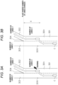
- Figs. 3A to 7B are diagrams illustrating a warning stop range X.
- each of Figs. 3A , 4A , 5A , 6A , and 7A illustrates, as a comparative example, a case where a function of setting the warning stop range X is not provided, that is, a case where a warning is uniformly issued if the lane on which the vehicle is traveling is not the left lane
- each of Figs. 3B , 4B , 5B , 6B , and 7B illustrates a case where the function of setting the warning stop range X is provided as in the present embodiment.
- Figs. 3A and 3B are diagrams illustrating the warning stop range when a road on which the vehicle is traveling branches at a branch point.
- a road 301 including two lanes 301r and 3011 branches into roads 302 and 303 each which is one lane at a branch point 304.
- a vehicle C is traveling on the road 301.
- the vehicle C may intentionally travel on the right lane 301r in advance on the road 301 on which the vehicle C is traveling.
- a warning is issued when the vehicle C travels on the right lane 301r, which may cause discomfort to the driver.
- a predetermined range is set on the road 301 on an upstream side of the branch point 304. That is, after a distance between the vehicle C and the branch point 304 becomes equal to or less than a predetermined distance, the warning is not issued until and branch point 304 is passed. Accordingly, a warning is not issued when the vehicle C travels on the right lane 301r in advance, so that the driver is prevented from feeling discomfort.
- Figs. 4A and 4B are diagrams illustrating the warning stop range when the road on which the vehicle is traveling branches at a branch point after the number of right lanes is increased.
- the vehicle C is traveling on the road 401.
- the vehicle when the vehicle is about to proceed to the lane 402, the vehicle may intentionally travel on the right lane 401r in advance on the road 401 on which the vehicle is traveling.
- a warning is issued when the vehicle C travels on the right lane 40 1r, which may cause discomfort to the driver.
- a warning is issued when the vehicle moves to the lane 402 to travel, the driver may feel uncomfortable, the driver may feel uncomfortable.
- a range is set on the road 401 that includes the upstream side of the branch point 403 and the upstream side of the position 404 where the right lane 402 is added. That is, after a distance between the vehicle C and the position 404 becomes equal to or less than a predetermined distance, the warning is not issued until and branch point 403 is passed. Accordingly, a warning is not issued when the vehicle travels on the right lane 401r in advance and when the vehicle moves to the lane 402, so that the driver is prevented from feeling discomfort.
- Figs. 5A and 5B are diagrams illustrating the warning stop range when the road on which the vehicle is traveling branches at a branch point after the number of left lanes is increased.
- a left lane 501l of a road 501 including two lanes 501r and 501l branches at a branch point 503 after two lanes 502r and 502l that form another road 502 are added.
- the vehicle C is traveling on the road 501.
- a warning is also issued when the vehicle C is traveling on the left lane 501l of the road 501 on which the vehicle C is traveling, which may cause discomfort to the driver.
- a range is set on the road 501 from the branch point 503 to the position 504 where the lanes 502r and 502l are added on the upstream side of the branch point 503. That is, a warning is not issued after passing the position 504 where the lanes 502r and 502l are added until the branch point 503 is passed. As a result, a warning is not issued when the vehicle C is apparently not traveling on the left lane, so that the driver is prevented from feeling discomfort.
- Figs. 6A and 6B are diagrams illustrating the warning stop range when there is a merging lane merging with a road on which the vehicle is traveling from the left side.
- a merging lane 602 is connected to a left lane 601l of a road 601 including two lanes 601r and 6011.
- the vehicle C is traveling on the road 601.
- a warning is also issued when the vehicle C is traveling on the left lane 601l of the road 601 on which the vehicle C is traveling, which may cause discomfort to the driver.
- the vehicle may intentionally travel on the right lane 601r in advance. This is the case of avoiding another vehicle changing the lane from the merging lane 602 to the road 601.
- a warning is issued when the vehicle C travels on the right lane 601r, which may cause discomfort to the driver.
- a range is set on the road 601 that includes the entire area of the merging lane 602 and the upstream side of a starting point 603 of the merging lane 602. That is, after a distance between the vehicle C and the starting point 603 becomes equal to or less than a predetermined distance, the warning is not issued until the merging lane 602 is passed. Accordingly, a warning is not issued when the vehicle is apparently not traveling on the left lane and when the vehicle is traveling on the right lane 601r in advance, so that the driver is prevented from feeling discomfort.
- Figs. 7A and 7B are diagrams illustrating the warning stop range when a road on which the vehicle is traveling is a road including a merging lane that merges with on a left side of another road.
- the merging lane 602 is connected to the left lane 601l of the road 601 including two lanes 601r and 601l.
- the vehicle C is traveling on a road 604 including the merging lane 602.
- a warning is issued when merging to the road 601 from the road 604 on which the vehicle is traveling, which may cause discomfort to the driver.
- the entire area of the merging lane 602 on the road 601 is set as the warning stop range X. That is, after the vehicle C moves to the road 601, the warning is not issued until the merging lane 602 is passed. As a result, a warning is not issued when the vehicle is apparently not traveling on the left lane, so that the driver is prevented from feeling discomfort.
- the warning stop range X described in the embodiments is an example, and may be appropriately set on an upstream side and a downstream side of a road from a place where the number of lanes changes. Further, the presence or absence and a size of the warning stop range X may be changed according to a type (branching, merging, expressway exit, climbing lane, or the like) of the place where the number of lanes changes.
- the warning stop range X may be determined by distance or time.
- the time is, for example, a time until reaching the branch point, and can be calculated based on the vehicle speed.
- the warning stop range X is set by time, it is conceivable that the vehicle suddenly falls within the warning stop range X or exits the warning stop range X due to a change in vehicle state, particularly a change in vehicle speed. In this way, since there is a possibility that a variation in alarm may occur, it is desirable to set the range by distance.
- a travel route to a destination is set by the car navigation device, which is the information acquisition unit 110, as illustrated in Figs. 3A to 4B , if the travel route includes the branch points 304 and 403, it is known in advance that the vehicle will travel in a right lane, so that the warning stop range X may be made wider than when the travel route is not set.
- the present invention may be applied by treating a plurality of lanes other than the rightmost lane as one left lane, and determining whether the lane on which the vehicle is traveling is the left lane.
- a basic determination logic is to issue a warning when a lane on which the vehicle is traveling is not the left lane.
- a basic determination logic is to issue a warning when a lane on which the vehicle is traveling is the rightmost lane, that is, the passing lane.
- the warning control unit 102 also sets a warning stop range in which a warning is not issued if there is a place where the number of lanes changes on a route of the vehicle based on the vehicle position and the road information acquired by the information acquisition unit 110.
- a warning stop range in which a warning is not issued if there is a place where the number of lanes changes on a route of the vehicle based on the vehicle position and the road information acquired by the information acquisition unit 110.
- a warning stop range in which a warning is not issued if there is a place where the number of lanes changes on a route of the vehicle based on the vehicle position and the road information acquired by the information acquisition unit 110.
- the lane guiding device to which the present invention is applied is implemented by a computer device including a CPU, a ROM, a RAM, and the like, and functions of the respective units are implemented by executing, for example, a predetermined program stored in the ROM by the CPU.
- the lane guiding device to which the present invention is applied may be implemented by a plurality of cooperating computer devices.
Landscapes
- Physics & Mathematics (AREA)
- General Physics & Mathematics (AREA)
- Traffic Control Systems (AREA)
- Navigation (AREA)
Abstract
A lane guiding device (100) that performs lane guidance based on a vehicle position and road information acquired by an information acquisition unit (110), the lane guiding device (100) includes a warning control unit (102) configured to control issuing a warning when a lane on which a vehicle is traveling is not a left lane. The warning control unit (102) sets a warning stop range in which the warning is not issued when there is a place where the number of lanes changes on a route of the vehicle based on the vehicle position and the road information acquired by the information acquisition unit (110).
Description
- The present invention relates to a lane guiding device.
-
Patent Literature 1 discloses a lane guiding device that warns, by using a display device and/or an audio output device, a driver to change a lane to a driving lane when it is determined that a state in which a vehicle is traveling on a passing lane of an expressway continues for a predetermined time. - Patent Literature 1:
JP2006-79356A - In
Patent Literature 1, a warning is issued when it is determined that the state in which a vehicle is traveling on a passing lane of an expressway continues for a predetermined time, but the vehicle may intentionally travel on the passing lane if there is a place where the number of lanes changes on a route of the vehicle. If a warning is issued in this case, the driver may feel uncomfortable. - The present invention has been made in view of such circumstances, and it is an object of the present invention to provide lane guidance that does not cause discomfort to a driver.
- The present invention relates to a lane guiding device that performs lane guidance based on a vehicle position and road information acquired by an information acquisition unit, the lane guiding device including a warning control unit configured to issue a warning when a lane on which a vehicle is traveling is not a left lane, in which the warning control unit sets a warning stop range in which the warning is not issued when there is a place where the number of lanes changes on a route of the vehicle based on the vehicle position and the road information acquired by the information acquisition unit.
- According to the present invention, it is possible to perform lane guidance that does not cause discomfort to a driver.
-
-
Fig. 1 is a diagram illustrating a configuration of a lane guiding system according to an embodiment. -
Fig. 2 is a flowchart illustrating a process executed by a lane guiding device according to the embodiment. -
Figs. 3A and 3B are diagrams illustrating a warning stop range. -
Figs. 4A and 4B are diagrams illustrating a warning stop range. -
Figs. 5A and 5B are diagrams illustrating a warning stop range. -
Figs. 6A and 6B are diagrams illustrating a warning stop range. -
Figs. 7A and 7B are diagrams illustrating a warning stop range. - A lane guiding device according to an embodiment of the present invention is a lane guiding device (100) that performs lane guidance based on a vehicle position and road information acquired by an information acquisition unit (110), the lane guiding device including a warning control unit (102) configured to issue a warning when a lane on which a vehicle is traveling is not a left lane, in which the warning control unit (102) sets a warning stop range in which the warning is not issued when there is a place where the number of lanes changes on a route of the vehicle based on the vehicle position and the road information acquired by the information acquisition unit (110).
- As a result, it is possible to perform lane guidance that does not cause discomfort to a driver by not issuing a warning in a situation in which it is appropriate that a lane on which the vehicle is traveling is not a left lane.
- Hereinafter, preferred embodiments of the present invention will be described with reference to the accompanying drawings.
-
Fig. 1 illustrates a configuration of a lane guiding system according to an embodiment. - The lane guiding system includes a lane guiding
device 100, aninformation acquisition unit 110, and awarning unit 120. - The
information acquisition unit 110 is a navigation device generally referred to as a car navigation device, and acquires road information relating to a vehicle position which is a current position of a vehicle and a road including a road on which the vehicle is traveling. Theinformation acquisition unit 110 detects the vehicle position by using, for example, a global positioning system (GPS) receiver, a gyroscope, a vehicle speed sensor, and a ground magnetic sensor. Theinformation acquisition unit 110 stores map information and can acquire the road information. The road information includes information such as a road type of each road such as a national road or an expressway, the number of lanes, a branch point, information of a merging point, and to which lane position each position coordinate corresponds. - The lane guiding
device 100 includes a drivinglane determination unit 101 and awarning control unit 102, and performs lane guidance based on the vehicle position and the road information acquired by theinformation acquisition unit 110. The lane guidingdevice 100 is implemented by a computer device including, for example, a CPU, a ROM, and a RAM, and functions of therespective units - The driving
lane determination unit 101 determines a lane on which the vehicle is traveling. Based on the vehicle position and the road information acquired by theinformation acquisition unit 110, it is possible to determine on which lane the vehicle is traveling. Alternatively, by recognizing the white line using an in-vehicle camera (not illustrated), the number of left and right white lines, a type of a white line (whether the white line is a solid line or a broken line), and the like may be determined, so as to determine on which lane the vehicle is traveling. - When the lane determined by the driving lane determination unit 101 (the lane on which the vehicle is traveling) is not the left lane, the
warning control unit 102 performs control such that a warning prompting a driver to change the lane is issued using thewarning unit 120. This makes it possible to assist the vehicle to travel on the left lane. If there are two or more lanes in one direction, in principle, it is necessary to use the first lane (first traffic zone) counted from the left side. - The
warning control unit 102 sets a warning stop range in which a warning is not issued if there is a place where the number of lanes changes on a route of the vehicle based on the vehicle position and the road information acquired by theinformation acquisition unit 110. When the vehicle is within the warning stop range, thewarning control unit 102 does not issue a warning when the lane determined by the driving lane determination unit 101 (the lane on which the vehicle is traveling) is not the left lane. The warning stop range will be described later with reference toFigs. 3A to 7B . - The
warning unit 120 issues a warning prompting the driver to change the lane under the control of the lane guidingdevice 100. A type of the warning is not limited, and may be, for example, a warning by audio output, a warning by display of characters and images on a meter panel, a car navigation screen, or the like, and a warning by lighting or blinking of a predetermined lamp. -
Fig. 2 is a flowchart illustrating a process executed by the lane guidingdevice 100. The flowchart ofFig. 2 is repeatedly executed. Although not illustrated in the flowchart, in parallel with the execution of the flowchart ofFig. 2 , thewarning control unit 102 sets the warning stop range if there is a place where the number of lanes changes on the route based on the vehicle position and the road information acquired by theinformation acquisition unit 110. - In step S1, the
warning control unit 102 determines whether a lane determined by the driving lane determination unit 101 (the lane on which the vehicle is traveling) is the left lane. If the lane on which the vehicle is traveling is not the left lane, the process proceeds to step S2. If the lane on which the vehicle is traveling is the left lane, the flowchart ends. - In step S2, the
warning control unit 102 determines whether the vehicle is in the warning stop range. If the vehicle is not in the warning stop range, the process proceeds to step S3. If the vehicle is in the warning stop range, the flowchart ends. - In step S3, the
warning control unit 102 issues, by using thewarning unit 120, a warning prompting the driver to change the lane. It should be noted that, continuation of a predetermined time since it is determined in step S1 that the lane on which the vehicle is traveling is not the left lane may be added to the condition for warning. - Details of the control by the
warning control unit 102 will be described below with reference toFigs. 3A to 7B . -
Figs. 3A to 7B are diagrams illustrating a warning stop range X. In each ofFigs. 3A to 7B , each ofFigs. 3A ,4A ,5A ,6A , and7A illustrates, as a comparative example, a case where a function of setting the warning stop range X is not provided, that is, a case where a warning is uniformly issued if the lane on which the vehicle is traveling is not the left lane, and each ofFigs. 3B ,4B ,5B ,6B , and7B illustrates a case where the function of setting the warning stop range X is provided as in the present embodiment. -
Figs. 3A and 3B are diagrams illustrating the warning stop range when a road on which the vehicle is traveling branches at a branch point. In the illustrated example, aroad 301 including twolanes roads branch point 304. A vehicle C is traveling on theroad 301. - In this case, when the vehicle is about to proceed to the
road 302 that branches to the right, the vehicle C may intentionally travel on theright lane 301r in advance on theroad 301 on which the vehicle C is traveling. - However, as shown in
Fig. 3A , in the comparative example, a warning is issued when the vehicle C travels on theright lane 301r, which may cause discomfort to the driver. - Therefore, as shown in
Fig. 3B , in the present embodiment, as the warning stop range X, a predetermined range is set on theroad 301 on an upstream side of thebranch point 304. That is, after a distance between the vehicle C and thebranch point 304 becomes equal to or less than a predetermined distance, the warning is not issued until andbranch point 304 is passed. Accordingly, a warning is not issued when the vehicle C travels on theright lane 301r in advance, so that the driver is prevented from feeling discomfort. -
Figs. 4A and 4B are diagrams illustrating the warning stop range when the road on which the vehicle is traveling branches at a branch point after the number of right lanes is increased. In the illustrated example, aright lane 401r of aroad 401 including twolanes 401r and 401l branches at abranch point 403 after a onelane 402, which is a road leading to an exit of an expressway or another road, is added. The vehicle C is traveling on theroad 401. - In this case, when the vehicle is about to proceed to the
lane 402, the vehicle may intentionally travel on theright lane 401r in advance on theroad 401 on which the vehicle is traveling. - However, as shown in
Fig. 4A , in the comparative example, a warning is issued when the vehicle C travels on the right lane 40 1r, which may cause discomfort to the driver. In addition, since a warning is issued when the vehicle moves to thelane 402 to travel, the driver may feel uncomfortable, the driver may feel uncomfortable. - As shown in
Fig. 4B , in the present embodiment, as the warning stop range X, a range is set on theroad 401 that includes the upstream side of thebranch point 403 and the upstream side of theposition 404 where theright lane 402 is added. That is, after a distance between the vehicle C and theposition 404 becomes equal to or less than a predetermined distance, the warning is not issued until andbranch point 403 is passed. Accordingly, a warning is not issued when the vehicle travels on theright lane 401r in advance and when the vehicle moves to thelane 402, so that the driver is prevented from feeling discomfort. -
Figs. 5A and 5B are diagrams illustrating the warning stop range when the road on which the vehicle is traveling branches at a branch point after the number of left lanes is increased. In the illustrated example, like a junction of an expressway, a left lane 501l of aroad 501 including twolanes 501r and 501l branches at abranch point 503 after twolanes 502r and 502l that form anotherroad 502 are added. The vehicle C is traveling on theroad 501. - In this case, of the
road 501 on which the vehicle C is traveling, if the vehicle C is traveling on the left lane 501l, after the twolanes 502r and 502l are added, the vehicle C apparently does not travel on the left lane. - Therefore, as shown in
Fig. 5A , in the comparative example, a warning is also issued when the vehicle C is traveling on the left lane 501l of theroad 501 on which the vehicle C is traveling, which may cause discomfort to the driver. - As shown in
Fig. 5B , in the present embodiment, as the warning stop range X, a range is set on theroad 501 from thebranch point 503 to theposition 504 where thelanes 502r and 502l are added on the upstream side of thebranch point 503. That is, a warning is not issued after passing theposition 504 where thelanes 502r and 502l are added until thebranch point 503 is passed. As a result, a warning is not issued when the vehicle C is apparently not traveling on the left lane, so that the driver is prevented from feeling discomfort. -
Figs. 6A and 6B are diagrams illustrating the warning stop range when there is a merging lane merging with a road on which the vehicle is traveling from the left side. In the illustrated example, amerging lane 602 is connected to a left lane 601l of aroad 601 including twolanes road 601. - In this case, of the
road 601 on which the vehicle C is traveling, if the vehicle C is traveling on the left lane 601l, after themerging lane 602 is added, the vehicle C apparently does not travel on the left lane. - Therefore, as shown in
Fig. 6A , in the comparative example, a warning is also issued when the vehicle C is traveling on the left lane 601l of theroad 601 on which the vehicle C is traveling, which may cause discomfort to the driver. - When there is the
merging lane 602 merging from the left side, although illustration is omitted, on theroad 601 on which the vehicle is traveling, the vehicle may intentionally travel on theright lane 601r in advance. This is the case of avoiding another vehicle changing the lane from themerging lane 602 to theroad 601. - However, in the comparative example, a warning is issued when the vehicle C travels on the
right lane 601r, which may cause discomfort to the driver. - Therefore, as shown in
Fig. 6B , in the present embodiment, as the warning stop range X, a range is set on theroad 601 that includes the entire area of themerging lane 602 and the upstream side of astarting point 603 of themerging lane 602. That is, after a distance between the vehicle C and thestarting point 603 becomes equal to or less than a predetermined distance, the warning is not issued until themerging lane 602 is passed. Accordingly, a warning is not issued when the vehicle is apparently not traveling on the left lane and when the vehicle is traveling on theright lane 601r in advance, so that the driver is prevented from feeling discomfort. -
Figs. 7A and 7B are diagrams illustrating the warning stop range when a road on which the vehicle is traveling is a road including a merging lane that merges with on a left side of another road. In the illustrated example, as inFigs. 6A and 6B , themerging lane 602 is connected to the left lane 601l of theroad 601 including twolanes 601r and 601l. The vehicle C is traveling on aroad 604 including themerging lane 602. - In this case, when the vehicle C travels to move from the
road 604 to theroad 601, the vehicle C is apparently not traveling on the left lane. - Therefore, as shown in
Fig. 7A , in the comparative example, a warning is issued when merging to theroad 601 from theroad 604 on which the vehicle is traveling, which may cause discomfort to the driver. - Therefore, as shown in
Fig. 7B , in the present embodiment, the entire area of themerging lane 602 on theroad 601 is set as the warning stop range X. That is, after the vehicle C moves to theroad 601, the warning is not issued until themerging lane 602 is passed. As a result, a warning is not issued when the vehicle is apparently not traveling on the left lane, so that the driver is prevented from feeling discomfort. - As described above, it is possible to perform lane guidance that does not cause discomfort to a driver by not issuing a warning in a situation in which there is a place where the number of lanes changes due to branching, merging, an exit of an expressway, or the like, and it is appropriate that a lane on which the vehicle is traveling is not a left lane.
- The warning stop range X described in the embodiments is an example, and may be appropriately set on an upstream side and a downstream side of a road from a place where the number of lanes changes. Further, the presence or absence and a size of the warning stop range X may be changed according to a type (branching, merging, expressway exit, climbing lane, or the like) of the place where the number of lanes changes.
- The warning stop range X may be determined by distance or time. The time is, for example, a time until reaching the branch point, and can be calculated based on the vehicle speed. When the warning stop range X is set by time, it is conceivable that the vehicle suddenly falls within the warning stop range X or exits the warning stop range X due to a change in vehicle state, particularly a change in vehicle speed. In this way, since there is a possibility that a variation in alarm may occur, it is desirable to set the range by distance.
- Further, when a travel route to a destination is set by the car navigation device, which is the
information acquisition unit 110, as illustrated inFigs. 3A to 4B , if the travel route includes the branch points 304 and 403, it is known in advance that the vehicle will travel in a right lane, so that the warning stop range X may be made wider than when the travel route is not set. - In the case of three or more lanes on one direction, it is possible to travel not only the first traffic zone but also a traffic zone other than the rightmost lane (passing lane). In the case of three or more lanes on one direction, for example, the present invention may be applied by treating a plurality of lanes other than the rightmost lane as one left lane, and determining whether the lane on which the vehicle is traveling is the left lane.
- Next, a second embodiment will be described. The configuration and the basic processing operation of the lane guiding system are the same as those of the first embodiment.
- In the first embodiment, a basic determination logic is to issue a warning when a lane on which the vehicle is traveling is not the left lane. On the other hand, in the second embodiment, a basic determination logic is to issue a warning when a lane on which the vehicle is traveling is the rightmost lane, that is, the passing lane.
- In the present embodiment, the
warning control unit 102 also sets a warning stop range in which a warning is not issued if there is a place where the number of lanes changes on a route of the vehicle based on the vehicle position and the road information acquired by theinformation acquisition unit 110. In the present embodiment, as shown inFigs. 3A to 4B , when the vehicle is intentionally traveling on the right lane (passing lane) 301r or 401r in advance, a warning is not issued, so that the driver is prevented from feeling discomfort. - Although the embodiments of the present invention are described in detail with reference to the drawings, the embodiments are merely a specific example for carrying out the present invention. The technical scope of the present invention is not limited to the example. Various modifications are possible without departing from the spirit of the present invention, and the modifications are also included in the technical scope of the present invention.
- In the present invention, it is assumed that the vehicle travels on the left side of a road in left-hand traffic as in Japan, but the present invention can also be applied to the case of right-hand traffic by reading the terms "left" and "right" interchangeably.
- The lane guiding device to which the present invention is applied is implemented by a computer device including a CPU, a ROM, a RAM, and the like, and functions of the respective units are implemented by executing, for example, a predetermined program stored in the ROM by the CPU. The lane guiding device to which the present invention is applied may be implemented by a plurality of cooperating computer devices.
-
- 100: lane guiding device
- 101: driving lane determination unit
- 102: warning control unit
- 110: information acquisition unit
- 120: warning unit
Claims (8)
- A lane guiding device (100) that performs lane guidance based on a vehicle position and road information acquired by an information acquisition unit (110), the lane guiding device (100) comprising:a warning control unit (102) configured to control issuing a warning when a lane on which a vehicle is traveling is not a left lane,wherein the warning control unit (102) sets a warning stop range in which the warning is not issued when there is a place where the number of lanes changes on a route of the vehicle based on the vehicle position and the road information acquired by the information acquisition unit (110).
- The lane guiding device (100) according to claim 1,
wherein when a road on which the vehicle is traveling branches at a branch point, the warning stop range is set to a predetermined range on an upstream side of the branch point on the road. - The lane guiding device (100) according to claim 1,wherein when a road on which the vehicle is traveling branches at a branch point after the number of right lanes is increased,the warning stop range is a range on the road that includes an upstream side of the branch point and an upstream side of a position where the number of the right lane is increased.
- The lane guiding device (100) according to claim 2 or 3,wherein the information acquisition unit (110) is a car navigation device configured to set a travel route to a destination, andwherein when the travel route includes a branch point, the warning stop range is wider than when the travel route is not set.
- The lane guiding device (100) according to claim 1,wherein when a road on which the vehicle is traveling branches at a branch point after the number of left lanes is increased,the warning stop range is a range on the road from the branch point to a position where the number of the left lane is increased on an upstream side of the branch point.
- The lane guiding device (100) according to claim 1,
wherein when there is a merging lane merging with a road on which the vehicle is traveling from a left side, the warning stop range is set to a range on the road that includes an entire area of the merging lane and an upstream side of a starting point of the merging lane. - The lane guiding device (100) according to claim 1,
wherein when a road on which the vehicle is traveling is a road including a merging lane that merges with a left side of another road, the warning stop range is set on the other road to an entire area of the merging lane. - A lane guiding device (100) that performs lane guidance based on a vehicle position and road information acquired by an information acquisition unit (110), the lane guiding device (100) comprising:a warning control unit (102) configured to control issuing a warning when a lane on which a vehicle is traveling is a passing lane,wherein the warning control unit (102) sets a warning stop range in which the warning is not issued when there is a place where the number of lanes changes on a route of the vehicle based on the vehicle position and the road information acquired by the information acquisition unit (110).
Applications Claiming Priority (1)
| Application Number | Priority Date | Filing Date | Title |
|---|---|---|---|
| JP2022170837A JP2024062771A (en) | 2022-10-25 | 2022-10-25 | Lane Guidance Device |
Publications (1)
| Publication Number | Publication Date |
|---|---|
| EP4361993A1 true EP4361993A1 (en) | 2024-05-01 |
Family
ID=88236680
Family Applications (1)
| Application Number | Title | Priority Date | Filing Date |
|---|---|---|---|
| EP23200339.2A Pending EP4361993A1 (en) | 2022-10-25 | 2023-09-28 | Lane guiding device |
Country Status (2)
| Country | Link |
|---|---|
| EP (1) | EP4361993A1 (en) |
| JP (1) | JP2024062771A (en) |
Citations (4)
| Publication number | Priority date | Publication date | Assignee | Title |
|---|---|---|---|---|
| JP2006079356A (en) | 2004-09-09 | 2006-03-23 | Denso Corp | Lane guide device |
| DE102009021283A1 (en) * | 2009-05-14 | 2010-11-18 | GM Global Technology Operations, Inc., Detroit | Device for assisting vehicle driver during observation to operation mode according to driving instruction, has unit to deliver information obtained from environment data to driver and traffic lane change reference information to lane |
| US20170082452A1 (en) * | 2014-06-10 | 2017-03-23 | Clarion Co., Ltd. | Lane selecting device, vehicle control system and lane selecting method |
| US20220163341A1 (en) * | 2019-03-22 | 2022-05-26 | Faurecia Clarion Electronics Co., Ltd. | Navigation system |
Family Cites Families (5)
| Publication number | Priority date | Publication date | Assignee | Title |
|---|---|---|---|---|
| JP2004086836A (en) * | 2002-07-03 | 2004-03-18 | Isuzu Motors Ltd | Travel lane guidance system |
| JP4777805B2 (en) * | 2006-03-23 | 2011-09-21 | アルパイン株式会社 | Vehicle warning guidance device |
| JP4826393B2 (en) * | 2006-08-31 | 2011-11-30 | アイシン・エィ・ダブリュ株式会社 | Route guidance system and route guidance method |
| JP5768666B2 (en) * | 2011-11-04 | 2015-08-26 | トヨタ自動車株式会社 | Vehicle travel support device and boundary line recognition device |
| DE102018220127A1 (en) * | 2018-11-23 | 2020-05-28 | Ford Global Technologies, Llc | Lane change assistance system |
-
2022
- 2022-10-25 JP JP2022170837A patent/JP2024062771A/en active Pending
-
2023
- 2023-09-28 EP EP23200339.2A patent/EP4361993A1/en active Pending
Patent Citations (4)
| Publication number | Priority date | Publication date | Assignee | Title |
|---|---|---|---|---|
| JP2006079356A (en) | 2004-09-09 | 2006-03-23 | Denso Corp | Lane guide device |
| DE102009021283A1 (en) * | 2009-05-14 | 2010-11-18 | GM Global Technology Operations, Inc., Detroit | Device for assisting vehicle driver during observation to operation mode according to driving instruction, has unit to deliver information obtained from environment data to driver and traffic lane change reference information to lane |
| US20170082452A1 (en) * | 2014-06-10 | 2017-03-23 | Clarion Co., Ltd. | Lane selecting device, vehicle control system and lane selecting method |
| US20220163341A1 (en) * | 2019-03-22 | 2022-05-26 | Faurecia Clarion Electronics Co., Ltd. | Navigation system |
Also Published As
| Publication number | Publication date |
|---|---|
| JP2024062771A (en) | 2024-05-10 |
Similar Documents
| Publication | Publication Date | Title |
|---|---|---|
| US10169997B2 (en) | Vehicle alert apparatus | |
| EP3333820B1 (en) | Driving plan device, travel support device, and driving plan method | |
| US10325494B2 (en) | Route guidance device and route guidance method | |
| US10597031B2 (en) | Drive assist apparatus | |
| US9607514B2 (en) | Drive assist device | |
| US20060009904A1 (en) | Vehicular navigation system | |
| EP4202883A1 (en) | Scene evaluation device, travel support device, and scene evaluation method | |
| EP3327695A1 (en) | Driving plan device, travel support device, and driving plan method | |
| CN111754793B (en) | Vehicle driving support device | |
| EP3333819A1 (en) | Scene evaluation device, travel support device, and scene evaluation method | |
| EP3660455A1 (en) | Travel assistance method and travel assistance device | |
| US10240941B2 (en) | Traffic lane guidance system for vehicle and traffic lane guidance method for vehicle | |
| CN111149140A (en) | Driving assistance method and driving assistance device | |
| US20230408285A1 (en) | Lane determination apparatus, lane-change determination program, and data structure | |
| EP3680619A1 (en) | Driving assistance method and driving assistance device | |
| US11332068B2 (en) | Direction indicator control method and direction indicator control device | |
| US11333516B2 (en) | Lane guidance system and lane guidance program | |
| EP2260267B1 (en) | Navigation device and navigation method | |
| RU2687393C1 (en) | Lane display device and lane display method | |
| WO2020058741A1 (en) | Automatic driving control method and automatic driving control system | |
| US11493356B2 (en) | Direction indicator control method and direction indicator control device | |
| CN110023718B (en) | Route guidance method and route guidance device | |
| US20220018680A1 (en) | Route setting apparatus, route setting method, program, and map data | |
| US20190066491A1 (en) | Driver assistance system and driver assistance method | |
| JP2024062771A (en) | Lane Guidance Device |
Legal Events
| Date | Code | Title | Description |
|---|---|---|---|
| PUAI | Public reference made under article 153(3) epc to a published international application that has entered the european phase |
Free format text: ORIGINAL CODE: 0009012 |
|
| STAA | Information on the status of an ep patent application or granted ep patent |
Free format text: STATUS: REQUEST FOR EXAMINATION WAS MADE |
|
| 17P | Request for examination filed |
Effective date: 20231020 |
|
| AK | Designated contracting states |
Kind code of ref document: A1 Designated state(s): AL AT BE BG CH CY CZ DE DK EE ES FI FR GB GR HR HU IE IS IT LI LT LU LV MC ME MK MT NL NO PL PT RO RS SE SI SK SM TR |