EP4361747A1 - Automatic transport control method and automatic transport system using automatically guided vehicle - Google Patents
Automatic transport control method and automatic transport system using automatically guided vehicle Download PDFInfo
- Publication number
- EP4361747A1 EP4361747A1 EP22878791.7A EP22878791A EP4361747A1 EP 4361747 A1 EP4361747 A1 EP 4361747A1 EP 22878791 A EP22878791 A EP 22878791A EP 4361747 A1 EP4361747 A1 EP 4361747A1
- Authority
- EP
- European Patent Office
- Prior art keywords
- node
- automatic
- production facility
- guidance vehicle
- location
- Prior art date
- Legal status (The legal status is an assumption and is not a legal conclusion. Google has not performed a legal analysis and makes no representation as to the accuracy of the status listed.)
- Pending
Links
Images


Classifications
-
- G—PHYSICS
- G05—CONTROLLING; REGULATING
- G05B—CONTROL OR REGULATING SYSTEMS IN GENERAL; FUNCTIONAL ELEMENTS OF SUCH SYSTEMS; MONITORING OR TESTING ARRANGEMENTS FOR SUCH SYSTEMS OR ELEMENTS
- G05B19/00—Program-control systems
- G05B19/02—Program-control systems electric
- G05B19/418—Total factory control, i.e. centrally controlling a plurality of machines, e.g. direct or distributed numerical control [DNC], flexible manufacturing systems [FMS], integrated manufacturing systems [IMS] or computer integrated manufacturing [CIM]
- G05B19/4189—Total factory control, i.e. centrally controlling a plurality of machines, e.g. direct or distributed numerical control [DNC], flexible manufacturing systems [FMS], integrated manufacturing systems [IMS] or computer integrated manufacturing [CIM] characterised by the transport system
- G05B19/41895—Total factory control, i.e. centrally controlling a plurality of machines, e.g. direct or distributed numerical control [DNC], flexible manufacturing systems [FMS], integrated manufacturing systems [IMS] or computer integrated manufacturing [CIM] characterised by the transport system using automatic guided vehicles [AGV]
-
- G—PHYSICS
- G05—CONTROLLING; REGULATING
- G05D—SYSTEMS FOR CONTROLLING OR REGULATING NON-ELECTRIC VARIABLES
- G05D1/00—Control of position, course, altitude or attitude of land, water, air or space vehicles, e.g. using automatic pilots
- G05D1/60—Intended control result
- G05D1/656—Interaction with payloads or external entities
- G05D1/667—Delivering or retrieving payloads
-
- G—PHYSICS
- G05—CONTROLLING; REGULATING
- G05D—SYSTEMS FOR CONTROLLING OR REGULATING NON-ELECTRIC VARIABLES
- G05D1/00—Control of position, course, altitude or attitude of land, water, air or space vehicles, e.g. using automatic pilots
- G05D1/20—Control system inputs
- G05D1/22—Command input arrangements
- G05D1/229—Command input data, e.g. waypoints
-
- G—PHYSICS
- G05—CONTROLLING; REGULATING
- G05D—SYSTEMS FOR CONTROLLING OR REGULATING NON-ELECTRIC VARIABLES
- G05D1/00—Control of position, course, altitude or attitude of land, water, air or space vehicles, e.g. using automatic pilots
- G05D1/20—Control system inputs
- G05D1/24—Arrangements for determining position or orientation
-
- G—PHYSICS
- G05—CONTROLLING; REGULATING
- G05D—SYSTEMS FOR CONTROLLING OR REGULATING NON-ELECTRIC VARIABLES
- G05D1/00—Control of position, course, altitude or attitude of land, water, air or space vehicles, e.g. using automatic pilots
- G05D1/60—Intended control result
- G05D1/656—Interaction with payloads or external entities
- G05D1/661—Docking at a base station
-
- G—PHYSICS
- G05—CONTROLLING; REGULATING
- G05D—SYSTEMS FOR CONTROLLING OR REGULATING NON-ELECTRIC VARIABLES
- G05D1/00—Control of position, course, altitude or attitude of land, water, air or space vehicles, e.g. using automatic pilots
- G05D1/60—Intended control result
- G05D1/69—Coordinated control of the position or course of two or more vehicles
- G05D1/698—Control allocation
-
- G—PHYSICS
- G05—CONTROLLING; REGULATING
- G05D—SYSTEMS FOR CONTROLLING OR REGULATING NON-ELECTRIC VARIABLES
- G05D2105/00—Specific applications of the controlled vehicles
- G05D2105/20—Specific applications of the controlled vehicles for transportation
- G05D2105/28—Specific applications of the controlled vehicles for transportation of freight
-
- G—PHYSICS
- G05—CONTROLLING; REGULATING
- G05D—SYSTEMS FOR CONTROLLING OR REGULATING NON-ELECTRIC VARIABLES
- G05D2105/00—Specific applications of the controlled vehicles
- G05D2105/45—Specific applications of the controlled vehicles for manufacturing, maintenance or repairing
-
- G—PHYSICS
- G05—CONTROLLING; REGULATING
- G05D—SYSTEMS FOR CONTROLLING OR REGULATING NON-ELECTRIC VARIABLES
- G05D2107/00—Specific environments of the controlled vehicles
- G05D2107/70—Industrial sites, e.g. warehouses or factories
-
- G—PHYSICS
- G05—CONTROLLING; REGULATING
- G05D—SYSTEMS FOR CONTROLLING OR REGULATING NON-ELECTRIC VARIABLES
- G05D2109/00—Types of controlled vehicles
- G05D2109/10—Land vehicles
-
- Y—GENERAL TAGGING OF NEW TECHNOLOGICAL DEVELOPMENTS; GENERAL TAGGING OF CROSS-SECTIONAL TECHNOLOGIES SPANNING OVER SEVERAL SECTIONS OF THE IPC; TECHNICAL SUBJECTS COVERED BY FORMER USPC CROSS-REFERENCE ART COLLECTIONS [XRACs] AND DIGESTS
- Y02—TECHNOLOGIES OR APPLICATIONS FOR MITIGATION OR ADAPTATION AGAINST CLIMATE CHANGE
- Y02P—CLIMATE CHANGE MITIGATION TECHNOLOGIES IN THE PRODUCTION OR PROCESSING OF GOODS
- Y02P90/00—Enabling technologies with a potential contribution to greenhouse gas [GHG] emissions mitigation
- Y02P90/02—Total factory control, e.g. smart factories, flexible manufacturing systems [FMS] or integrated manufacturing systems [IMS]
Definitions
- the present disclosure relates to an automatic transportation control method and an automatic transportation system using an automatic guidance vehicle.
- the production facility is the electrode facility
- snaking of the jumbo rolls is corrected upon a winding operation of the electrode with an edge positioning controller (EPC) for securing a processing quality. It is difficult to automatically dock a vehicle that transports the jumbo rolls to the production facility due to the EPC snaking correction.
- EPC edge positioning controller
- the present disclosure has been made in an effort to provide an automatic transportation control method and an automatic transportation system using an automatic guidance vehicle, which are capable of automating transportation, loading, and unloading of raw materials such as jumbo rolls.
- An automatic transportation control method includes: moving, by an automatic guidance vehicle, to node #1 which is an initial reference location according to an instruction from an automatic transportation control apparatus; moving, by the automatic guidance vehicle, to node #2 which is a stand-by location before entering a production facility from the node #1; moving, by the automatic guidance vehicle, to node #3 for docking to the production facility from the node #2; and receiving, by the automatic guidance vehicle, a changed location coordinate value of the node #2 from the automatic transportation control apparatus, and traveling based on the changed location coordinate value of the node #2 when the node #2 is changed according to a work location change of the production facility.
- the automatic transportation control method may further include receiving, by the automatic guidance vehicle, a changed location coordinate value of the node #3 from the automatic transportation control apparatus, and traveling based on the changed location coordinate value of the node #3 when the node #3 is changed according to the work location change of the production facility.
- the automatic transportation control method may further include receiving, by the automatic transportation control apparatus, a work location change degree of the production facility from the production facility, and calculating the changed location coordinate value of the node #3 by reflecting a change amount of the work location in the location coordinate value of the node #3.
- the automatic transportation control method may further include receiving, by the automatic transportation control apparatus, a work location change degree of the production facility from the production facility, and calculating the changed location coordinate value of the node #2 by reflecting a change amount of the work location in the location coordinate value of the node #2.
- the automatic transportation control method may further include transmitting/receiving, by the automatic guidance vehicle and the production facility, information for loading or unloading a raw material through PIO communication while the automatic guidance vehicle moves from the node #2 to the node #3.
- An automatic transportation system of loading a raw material on a production facility or unloading the raw material from the production facility may include: an automatic guidance vehicle moving to node #1 which is an initial reference location, moving to node #2 which is a stand-by location before entering the production facility from the node #1, and moving to node #3 for docking to the production facility from the node #2; and an automatic transportation control apparatus receiving information on a work location change of the production facility from the production facility, and changing a location coordinate value of the node #2 according to the information on the work location change and transmitting the changed location coordinate value of the node #2 to the automatic guidance vehicle.
- the automatic transportation control apparatus may receive information on a work location change of the production facility from the production facility, and change a location coordinate value of the node #3 according to the information on the work location change and transmit the changed location coordinate value of the node #3 to the automatic guidance vehicle.
- the automatic transportation control apparatus may calculate the changed location coordinate value of the node #3 by reflecting a change amount of the work location in the location coordinate value of the node #3.
- the automatic transportation control apparatus may calculate the changed location coordinate value of the node #2 by reflecting a change amount of the work location in a set location coordinate value of the node #2.
- the automatic guidance vehicle may include a PIO sensor transmitting/receiving information for loading or unloading a raw material by performing PIO communication with a PIO sensor of the production facility while the automatic guidance vehicle moves from the node #2 to the node #3.
- the present disclosure provides an automatic transportation control method and an automatic transportation system using an automatic guidance vehicle, which are capable of automating transportation, loading, and unloading of raw materials such as jumbo rolls.
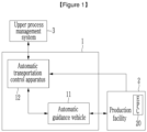
- FIG. 1 is a diagram schematically illustrating a production factory to which an automatic transportation system is applied according to an embodiment.
- the automatic transportation system 1 includes an automatic guidance vehicle 11 and an automatic transportation control apparatus 12.
- the automatic transportation control apparatus 12 may control the automatic guidance vehicle 11 based on information received from an upper process management system 3, a production facility 2, etc., through wired/wireless communication.
- the automatic transportation control apparatus 12 may adjust a location coordinate value indicating a location of a work node (e.g., node #2 N2 and node #3 N3) based on information on locations of turrets 21 and 22 received from the production facility 2, and transmit the location coordinate value to the automatic guidance vehicle 11 through the wireless communication.
- the automatic guidance vehicle 11 may travel according to the received work node.
- FIG. 2 is a layout diagram for describing movement of an automatic guidance vehicle according to an embodiment.
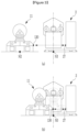
- FIG. 3 is a diagram illustrating before and after docking the automatic guidance vehicle to a production facility.
- the production facility 2 includes EPCs 20 facing each other, two turrets 21 and 22 facing each other, location driving units 23 and 24 facing each other adjusting locations of the turrets, lower fixation units 25 and 26 facing each other, and PIO sensors 27 facing each other.
- EPCs 20 facing each other
- two turrets 21 and 22 facing each other
- location driving units 23 and 24 facing each other adjusting locations of the turrets
- lower fixation units 25 and 26 facing each other
- PIO sensors 27 facing each other.
- the location driving units 23 and 24 are devices that are connected to the turrets 21 and 22 to move the locations of the turrets 21 and 22 horizontally (in an x-axis direction in FIG. 2 ).
- An EPC 20 (see FIG. 1 ) is a device that corrects snaking of an electrode member in order to match edge locations of electrode members upon a winding or unwinding operation of the electrode member.
- the EPC 20 may correct snaking by controlling the operations of the location driving units 23 and 24.
- the locations of the turrets 21 and 22 may horizontally move in the x-axis direction by snaking correction.
- the automatic guidance vehicle 11 includes a driving device 110, a transfer device 120, and a PIO sensor 130.
- the transfer device 120 as a device installed on the driving device 110 and loading and transporting a raw material (e.g., a jumbo roll) is movable in all x-axis, y-axis, and z-axis directions.
- the driving device 110 may move the automatic guidance vehicle 11 in the x-axis and y-axis directions according to control by the automatic transportation control apparatus 12.
- x-axis and y-axis direction movement ranges of the transfer device 120 are limited, so the driving device 110 may move for adjusting the location of the transfer device 120.
- An electrode member having a predetermined width and a predetermined length is wound on the jumbo roll.
- the automatic guidance vehicle 11 moves by the driving device 110, and the automatic guidance vehicle 11 is docked to the production facility 2 and the transfer device 120 may move to load and unload the jumbo roll 13.
- the PIO sensor 27 and the PIO sensor 130 may transmit/receive information for loading and unloading of a jumbo roll 13 between the automatic guidance vehicle 11 and the production facility 2 to/from each other by parallel input output (PIO) communication.
- PIO parallel input output
- Node #1 N1 means an initial reference location (X1, Y1) of the automatic guidance vehicle 11 for the production facility 2.
- a region (hereinafter, referred to as an entire movement region) in which the automatic guidance vehicle 11 may move in a production factory in which a production line is installed may be distinguished as coordinates.
- the entire movement region may be distinguished as a plurality of nodes defined by an x coordinate value of a predetermined unit (e.g., mm) set in the x-axis direction and a y coordinate value of a predetermined unit (e.g., mm) set in the y-axis direction.
- the entire movement region may include a movement region of the automatic guidance vehicle positioned in the x-axis direction and an entry region into the production facility positioned in the y-axis direction in order to dock the automatic guidance vehicle to the production facility in FIG. 2 .
- node #1 N1 which is the initial reference location (X1, Y1) is set as an initial point at which the automatic guidance vehicle is positioned in order to dock to the production facility 2.
- Node #1 N1 may be positioned in the movement region of the automatic guidance vehicle.
- the automatic guidance vehicle 11 may move up to node #1 N1 from an arbitrary start location in the entire movement region.
- node #1 N1 the automatic guidance vehicle 11 moves to node #2 N2 which is a location in which the automatic guidance vehicle 11 stands by before entering the production facility 2.
- PIO communication between the production facility 2 and the automatic guidance vehicle 11 from node #2 N2 may be enabled.
- x-axis and y-axis coordinate values X2, Y2 of node #2 N2 may be initially set.
- the automatic guidance vehicle 11 When the automatic guidance vehicle 11 starts to move from node #1 N1 to node #2 N2, the automatic guidance vehicle 11 may set a movement direction and a movement distance according to a location coordinate value of node #2 N2 set from the automatic transportation control apparatus 12. The automatic guidance vehicle 11 travels as long as the movement distance in the set movement direction.
- the location of node #2 N2 may be varied according to variation of a work location of the production facility 2. For example, while the locations of turrets 21 and 22 move by the control by the EPC 20, the location of node #2 N2 may also be changed. In particular, when the turrets 21 and 22 move in the x-axis direction, node #2 N2 should move jointly as much as the corresponding movement amount ⁇ X2.
- the EPC 20 may transmit movement information of the turrets 21 and 22 to the automatic transportation control apparatus 12, and the automatic transportation control apparatus 12 may calculate the location coordinate value of node #2 N2 changed based on a change amount of node #2 N2 based on the movement information of the turrets 21 and 22.
- the automatic transportation control apparatus 12 may transmit a location coordinate value (X2+ ⁇ X2, Y2) of node #2 N2 changed to the automatic guidance vehicle 11.
- ⁇ X2 may have a positive value
- ⁇ X2 may have a negative value.
- the automatic guidance vehicle 11 When the automatic guidance vehicle 11 starts to move from node #1 N1 to node #2 N2, the automatic guidance vehicle 11 may set the movement direction and the movement distance according to the changed location coordinate value of node #2 N2 received from the automatic transportation control apparatus 12. The automatic guidance vehicle 11 travels as long as the movement distance in the set movement direction.
- the automatic guidance vehicle 11 may receive the location coordinate value of node #2 N2 from the automatic transportation control apparatus 12 in real time while moving from node #1 N1 to node #2 N2, and correct a current movement direction and a current movement distance based on the received location coordinate value of node #2 N2. For example, while the automatic guidance vehicle 11 moves from node #1 N1 to node #2 N2, the automatic guidance vehicle 11 adjusts the movement direction by calculating a distance difference for each of the x-axis direction and the y-axis direction up to the location coordinate value (X2+ ⁇ X2, Y2) of node #2 N2 from a current location (X, Y), and move as long as a movement distance up to node #2 N2 changed from the current location.
- node #3 N3 means a location at which the automatic guidance vehicle 11 is docked to the production facility 2 to load or unload the jumbo roll 13.
- the automatic guidance vehicle 11 that moves from node #2 N2 to node #3 N3 transmits/receives information required for loading or unloading the jumbo roll 13 through PIO communication using the production facility 2 and each PIO sensor.
- the automatic guidance vehicle 11 moves from node #2 N2 to node #3 N3 while holding the jumbo roll 13, and as a result, the jumbo roll 13 held on the automatic guidance vehicle 11 may be chucked (loaded) on the turrets 21 and 22.
- the automatic guidance vehicle 11 moves from node #2 N2 to node #3 N3 to hold the jumbo roll 13 un-chucked (unloaded) from the turrets 21 and 22.
- the automatic guidance vehicle 11 and the production facility 2 may at least transmit/receive the following information for loading through the PIO communication.
- the automatic guidance vehicle 11 announces that the automatic guidance vehicle 11 is positioned in node #2 N2 to the production facility 2.
- the production facility 2 announces that the jumbo roll 13 may be loaded to the automatic guidance vehicle 11.
- the automatic guidance vehicle 11 announces moving from node #2 N2 to node #3 N3.
- the production facility 2 announces that the jumbo roll 13 may be loaded to the automatic guidance vehicle 11.
- the automatic guidance vehicle 11 is docked to node #3 N3 and requests a chucking operation to the production facility 2.
- the production facility 2 announces that chucking is being performed to the automatic guidance vehicle 11 in response to the request, and when chucking is completed, the production facility 2 may announce chucking completion to the automatic guidance vehicle 11.
- the automatic guidance vehicle 11 and the production facility 2 may at least transmit/receive the following information for unloading through the PIO communication.
- the automatic guidance vehicle 11 announces that the automatic guidance vehicle 11 is positioned in node #2 N2 to the production facility 2.
- the production facility 2 requests unloading of the jumbo roll 13 to the automatic guidance vehicle 11.
- the automatic guidance vehicle 11 announces moving from node #2 N2 to node #3 N3.
- the production facility 2 announces that the jumbo roll 13 may be unloaded.
- the automatic guidance vehicle 11 is docked to node #3 N3 and requests a un-chucking operation to the production facility 2.
- the production facility 2 announces that un-chucking is being performed to the automatic guidance vehicle 11 in response to the request, and when un-chucking is completed, the production facility 2 may announce un-chucking completion to the automatic guidance vehicle 11.
- the automatic guidance vehicle 11 reaches node #2 N2 in the y-axis direction. As illustrated in (b) of FIG. 3 , the automatic guidance vehicle 11 enters node #3 N3 from node #2 N2 and a center of the automatic guidance vehicle 11 reaches node #3 N3. Then, the automatic guidance vehicle 11 is docked to the production facility 2. After docking, in order to chuck the jumbo roll 13 on the turrets 21 and 22 or in order un-chuck the jumbo roll 13 from the turrets 21 and 22, the transfer device 120 may move in the z-axis direction.
- the automatic guidance vehicle 11 When the automatic guidance vehicle 11 starts to move from node #2 N2 to node #3 N3, the automatic guidance vehicle 11 may set the movement direction and the movement distance according to the current location coordinate value of node #3 N3. The automatic guidance vehicle 11 travels as long as the movement distance in the set movement direction.
- the location of node #3 N3 may be varied according to the variation of the work location of the production facility 2. For example, while the locations of turrets 21 and 22 move by the control by the EPC 20, the location of node #3 N3 may also be changed. In particular, when the turrets 21 and 22 move in the x-axis direction, node #3 N3 should move jointly as much as the corresponding movement amount ⁇ X3.
- the EPC 20 may transmit movement information of the turrets 21 and 22 to the automatic transportation control apparatus 12, and the automatic transportation control apparatus 12 may change the location coordinate value of node #3 N3 based on the movement information of the turrets 21 and 22, and transmit a changed location coordinate value (X3+AX3, Y3) of node #3 N3 to the automatic guidance vehicle 11.
- ⁇ X3 may have the positive value
- ⁇ X3 may have the negative value.
- the automatic guidance vehicle 11 may correct the current movement direction and the current movement distance based on the changed location coordinate value of node #3 N3. For example, while the automatic guidance vehicle 11 moves from node #2 N2 to node #3 N3, the automatic guidance vehicle 11 adjusts the movement direction by calculating the distance difference for each of the x-axis direction and the y-axis direction up to node #3 N3 from the current location (X, Y), and move as long as the movement distance up to node #3 N3 changed from the current location.
- the automatic guidance vehicle 11 may complete loading and unloading of the jumbo roll 13 by reaching node #3 N3, and then the automatic guidance vehicle 11 may move from node #3 N3 to node #4. After the automatic guidance vehicle 11 reaches node #3 N3, the transfer device 120 may move to a location for loading and unloading of the jumbo roll 13.
- FIG. 4 is a flowchart illustrating an operation of an automatic transportation system according to an embodiment.
- the automatic transportation control apparatus 12 may receive a raw material transport instruction such as the jumbo roll 13 from the upper process management system 3 (S0).
- the transport instruction may include information on a location of a warehouse storing the raw material, a location of the production facility, a work time, etc.
- the automatic guidance vehicle 11 may receive the transport instruction from the automatic transportation control apparatus 12, and move to node #1 N1 (S1). In the case of loading of the raw material, the automatic guidance vehicle 11 may move to the warehouse storing the raw material and hold the raw material, and then move to node #1 N1. In the case of unloading of the raw material, the automatic guidance vehicle 11 may move to node #1 N1 from the current location.
- the automatic guidance vehicle 11 may move from node #1 N1 to node #2 N2 (S2).
- the automatic transportation control apparatus 12 may receive a work location change degree of the production facility 2 from the EPC 20, and calculate the changed location coordinate value of node #2 N2 by reflecting a change amount of the work location in a predetermined location coordinate value of node #2 N2 (S3).
- the automatic guidance vehicle 11 may receive the changed location coordinate value of node #2 N2 from the automatic transportation control apparatus 12, determine the movement direction and the movement distance based on the changed location coordinate value of node #2 N2, and travel according to the determined movement direction and movement distance (S4).
- the automatic guidance vehicle 11 may move from node #2 N2 to node #3 N3 (S5). During step S5, the automatic guidance vehicle 11 may transmit/receive information for loading and unloading to/from the production facility 2 through the PIO communication.
- the automatic transportation control apparatus 12 may receive a work location change degree of the production facility 2 from the EPC 20, and calculate the changed location coordinate value of node #3 N3 by reflecting a change amount of the work location in the current location coordinate value of node #3 N3 (S6).
- the automatic guidance vehicle 11 may receive the changed location coordinate value of node #3 N3 from the automatic transportation control apparatus 12, determine the movement direction and the movement distance based on the changed location coordinate value of node #3 N3, and travel according to the determined movement direction and movement distance (S7).
- the automatic guidance vehicle 11 may be docked to the production facility 2, and then complete loading and unloading.
- the automatic guidance vehicle 11 completes loading and unloading, and then moves to node #4 (S8).
- the automatic transportation control method and the automatic transportation system may be applied. That is, the interface between the production facility and the automatic transportation system may be implemented through an embodiment of the present invention.
- the present invention may provide the interface between the production facility and the automatic guidance vehicle by transmitting the work node to the automatic guidance vehicle according to the movement of the turret.
- the automatic guidance vehicle may be automatically docked to the production facility.
Landscapes
- Engineering & Computer Science (AREA)
- Physics & Mathematics (AREA)
- General Physics & Mathematics (AREA)
- Automation & Control Theory (AREA)
- Aviation & Aerospace Engineering (AREA)
- Radar, Positioning & Navigation (AREA)
- Remote Sensing (AREA)
- General Engineering & Computer Science (AREA)
- Manufacturing & Machinery (AREA)
- Quality & Reliability (AREA)
- Control Of Position, Course, Altitude, Or Attitude Of Moving Bodies (AREA)
- General Factory Administration (AREA)
Abstract
Description
- This application claims priority to and the benefit of
Korean Patent Application No. 10-2021-0133508 filed in the Korean Intellectual Property Office on October 7, 2021 - The present disclosure relates to an automatic transportation control method and an automatic transportation system using an automatic guidance vehicle.
- In the related art, production workers manually carry raw materials such as jumbo rolls to load jumbo rolls on electrode facilities and unload the jumbo rolls from the electrode facilities. However, due to such a manual work, work efficiency of the production worker is added. Further, the jumbo rolls may drop while the jumbo rolls are transported and the jumbo rolls are loaded on and unloaded from the electrode facilities, so a safety accident may occur.
- Further, when the production facility is the electrode facility, snaking of the jumbo rolls is corrected upon a winding operation of the electrode with an edge positioning controller (EPC) for securing a processing quality. It is difficult to automatically dock a vehicle that transports the jumbo rolls to the production facility due to the EPC snaking correction.
- In order to solve the problem in the related art, the present disclosure has been made in an effort to provide an automatic transportation control method and an automatic transportation system using an automatic guidance vehicle, which are capable of automating transportation, loading, and unloading of raw materials such as jumbo rolls.
- An automatic transportation control method according to one feature of the present invention includes: moving, by an automatic guidance vehicle, to
node # 1 which is an initial reference location according to an instruction from an automatic transportation control apparatus; moving, by the automatic guidance vehicle, tonode # 2 which is a stand-by location before entering a production facility from thenode # 1; moving, by the automatic guidance vehicle, tonode # 3 for docking to the production facility from thenode # 2; and receiving, by the automatic guidance vehicle, a changed location coordinate value of thenode # 2 from the automatic transportation control apparatus, and traveling based on the changed location coordinate value of thenode # 2 when thenode # 2 is changed according to a work location change of the production facility. - The automatic transportation control method may further include receiving, by the automatic guidance vehicle, a changed location coordinate value of the
node # 3 from the automatic transportation control apparatus, and traveling based on the changed location coordinate value of thenode # 3 when thenode # 3 is changed according to the work location change of the production facility. - The automatic transportation control method may further include receiving, by the automatic transportation control apparatus, a work location change degree of the production facility from the production facility, and calculating the changed location coordinate value of the
node # 3 by reflecting a change amount of the work location in the location coordinate value of thenode # 3. - The automatic transportation control method may further include receiving, by the automatic transportation control apparatus, a work location change degree of the production facility from the production facility, and calculating the changed location coordinate value of the
node # 2 by reflecting a change amount of the work location in the location coordinate value of thenode # 2. - The automatic transportation control method may further include transmitting/receiving, by the automatic guidance vehicle and the production facility, information for loading or unloading a raw material through PIO communication while the automatic guidance vehicle moves from the
node # 2 to thenode # 3. - An automatic transportation system of loading a raw material on a production facility or unloading the raw material from the production facility may include: an automatic guidance vehicle moving to
node # 1 which is an initial reference location, moving tonode # 2 which is a stand-by location before entering the production facility from thenode # 1, and moving tonode # 3 for docking to the production facility from thenode # 2; and an automatic transportation control apparatus receiving information on a work location change of the production facility from the production facility, and changing a location coordinate value of thenode # 2 according to the information on the work location change and transmitting the changed location coordinate value of thenode # 2 to the automatic guidance vehicle. - The automatic transportation control apparatus may receive information on a work location change of the production facility from the production facility, and change a location coordinate value of the
node # 3 according to the information on the work location change and transmit the changed location coordinate value of thenode # 3 to the automatic guidance vehicle. - The automatic transportation control apparatus may calculate the changed location coordinate value of the
node # 3 by reflecting a change amount of the work location in the location coordinate value of thenode # 3. - The automatic transportation control apparatus may calculate the changed location coordinate value of the
node # 2 by reflecting a change amount of the work location in a set location coordinate value of thenode # 2. - The automatic guidance vehicle may include a PIO sensor transmitting/receiving information for loading or unloading a raw material by performing PIO communication with a PIO sensor of the production facility while the automatic guidance vehicle moves from the
node # 2 to thenode # 3. - The present disclosure provides an automatic transportation control method and an automatic transportation system using an automatic guidance vehicle, which are capable of automating transportation, loading, and unloading of raw materials such as jumbo rolls.
-
-
FIG. 1 is a diagram schematically illustrating a production factory to which an automatic transportation system is applied according to an embodiment. -
FIG. 2 is a layout diagram for describing movement of an automatic guidance vehicle according to an embodiment. -
FIG. 3 is a diagram illustrating before and after docking the automatic guidance vehicle to a production facility. -
FIG. 4 is a flowchart illustrating an operation of an automatic transportation system according to an embodiment. - Hereinafter, embodiments disclosed in this specification will be described in detail with reference to the accompanying drawings and the same or similar components are denoted by the same or similar reference numerals, and duplicated description thereof will be omitted. Suffixes "module" and/or "unit" for components used in the following description are given or mixed in consideration of easy preparation of the present disclosure only and do not have their own distinguished meanings or roles. Further, in describing an embodiment disclosed in the present invention, a detailed description of related known technologies will be omitted if it is determined that the detailed description makes the gist of the embodiment of the present invention unclear. Further, it is to be understood that the accompanying drawings are just used for easily understanding the embodiments disclosed in this specification and a technical spirit disclosed in this specification is not limited by the accompanying drawings and all changes, equivalents, or substitutes included in the spirit and the technical scope of the present invention are included.
- Terms including an ordinary number, such as first and second, are used for describing various elements, but the elements are not limited by the terms. The terms are used only to discriminate one element from another element.
- It should be understood that, when it is described that a component is "connected to" or "accesses" another component, the component may be directly connected to or access the other component or a third component may be present therebetween. In contrast, when it is described that a component is "directly connected to" or "directly accesses" another component, it is understood that no component is present between the component and the another component.
- In the present application, it should be understood that term "include" or "have"indicates that a feature, a number, a step, an operation, a component, a part or the combination thereof described in the specification is present, but does not exclude a possibility of presence or addition of one or more other features, numbers, steps, operations, components, parts or combinations thereof, in advance.
-
FIG. 1 is a diagram schematically illustrating a production factory to which an automatic transportation system is applied according to an embodiment. - As illustrated in
FIG. 1 , theautomatic transportation system 1 includes anautomatic guidance vehicle 11 and an automatictransportation control apparatus 12. The automatictransportation control apparatus 12 may control theautomatic guidance vehicle 11 based on information received from an upperprocess management system 3, aproduction facility 2, etc., through wired/wireless communication. For example, the automatictransportation control apparatus 12 may adjust a location coordinate value indicating a location of a work node (e.g.,node # 2 N2 andnode # 3 N3) based on information on locations ofturrets production facility 2, and transmit the location coordinate value to theautomatic guidance vehicle 11 through the wireless communication. Theautomatic guidance vehicle 11 may travel according to the received work node. -
FIG. 2 is a layout diagram for describing movement of an automatic guidance vehicle according to an embodiment. -
FIG. 3 is a diagram illustrating before and after docking the automatic guidance vehicle to a production facility. - In
FIG. 2 , theproduction facility 2 includesEPCs 20 facing each other, twoturrets location driving units lower fixation units PIO sensors 27 facing each other. This is an example for describing an embodiment, and the production facility to which the present invention is applied is not limited to contents illustrated inFIGS. 2 and3 . In the following description, the location of theautomatic guidance vehicle 11 may be determined based on a center in an entire structure of theautomatic guidance vehicle 11. - The
location driving units turrets turrets FIG. 2 ). An EPC 20 (seeFIG. 1 ) is a device that corrects snaking of an electrode member in order to match edge locations of electrode members upon a winding or unwinding operation of the electrode member. TheEPC 20 may correct snaking by controlling the operations of thelocation driving units turrets - The
automatic guidance vehicle 11 includes adriving device 110, atransfer device 120, and aPIO sensor 130. Thetransfer device 120 as a device installed on thedriving device 110 and loading and transporting a raw material (e.g., a jumbo roll) is movable in all x-axis, y-axis, and z-axis directions. Thedriving device 110 may move theautomatic guidance vehicle 11 in the x-axis and y-axis directions according to control by the automatictransportation control apparatus 12. x-axis and y-axis direction movement ranges of thetransfer device 120 are limited, so thedriving device 110 may move for adjusting the location of thetransfer device 120. An electrode member having a predetermined width and a predetermined length is wound on the jumbo roll. - The
automatic guidance vehicle 11 moves by thedriving device 110, and theautomatic guidance vehicle 11 is docked to theproduction facility 2 and thetransfer device 120 may move to load and unload thejumbo roll 13. Through communication according to a communication rule applied when moving logistics between equipments, thePIO sensor 27 and thePIO sensor 130 may transmit/receive information for loading and unloading of ajumbo roll 13 between theautomatic guidance vehicle 11 and theproduction facility 2 to/from each other by parallel input output (PIO) communication. For example, while theautomatic guidance vehicle 11 moves fromnode # 2 N2 tonode # 3 N3, theproduction facility 2 and theautomatic guidance vehicle 11 transmit/receive information through the PIO communication using thePIO sensors - As illustrated in
FIG. 2 , first, theautomatic guidance vehicle 11 according to an embodiment moves and reachesnode # 1 N1.Node # 1 N1 means an initial reference location (X1, Y1) of theautomatic guidance vehicle 11 for theproduction facility 2. A region (hereinafter, referred to as an entire movement region) in which theautomatic guidance vehicle 11 may move in a production factory in which a production line is installed may be distinguished as coordinates. For example, the entire movement region may be distinguished as a plurality of nodes defined by an x coordinate value of a predetermined unit (e.g., mm) set in the x-axis direction and a y coordinate value of a predetermined unit (e.g., mm) set in the y-axis direction. The entire movement region may include a movement region of the automatic guidance vehicle positioned in the x-axis direction and an entry region into the production facility positioned in the y-axis direction in order to dock the automatic guidance vehicle to the production facility inFIG. 2 . - In the entire movement region,
node # 1 N1 which is the initial reference location (X1, Y1) is set as an initial point at which the automatic guidance vehicle is positioned in order to dock to the production facility 2.Node # 1 N1 may be positioned in the movement region of the automatic guidance vehicle. Theautomatic guidance vehicle 11 may move up tonode # 1 N1 from an arbitrary start location in the entire movement region. - Subsequently to
node # 1 N1, theautomatic guidance vehicle 11 moves tonode # 2 N2 which is a location in which theautomatic guidance vehicle 11 stands by before entering theproduction facility 2. PIO communication between theproduction facility 2 and theautomatic guidance vehicle 11 fromnode # 2 N2 may be enabled. - x-axis and y-axis coordinate values X2, Y2 of
node # 2 N2 may be initially set. When theautomatic guidance vehicle 11 starts to move fromnode # 1 N1 tonode # 2 N2, theautomatic guidance vehicle 11 may set a movement direction and a movement distance according to a location coordinate value ofnode # 2 N2 set from the automatictransportation control apparatus 12. Theautomatic guidance vehicle 11 travels as long as the movement distance in the set movement direction. - The location of
node # 2 N2 may be varied according to variation of a work location of theproduction facility 2. For example, while the locations ofturrets EPC 20, the location ofnode # 2 N2 may also be changed. In particular, when theturrets node # 2 N2 should move jointly as much as the corresponding movement amount ΔX2. TheEPC 20 may transmit movement information of theturrets transportation control apparatus 12, and the automatictransportation control apparatus 12 may calculate the location coordinate value ofnode # 2 N2 changed based on a change amount ofnode # 2 N2 based on the movement information of theturrets transportation control apparatus 12 may transmit a location coordinate value (X2+ΔX2, Y2) ofnode # 2 N2 changed to theautomatic guidance vehicle 11. Whennode # 2 N2 moves to the right, ΔX2 may have a positive value and whennode # 2 N2 moves to the left, ΔX2 may have a negative value. - When the
automatic guidance vehicle 11 starts to move fromnode # 1 N1 tonode # 2 N2, theautomatic guidance vehicle 11 may set the movement direction and the movement distance according to the changed location coordinate value ofnode # 2 N2 received from the automatictransportation control apparatus 12. Theautomatic guidance vehicle 11 travels as long as the movement distance in the set movement direction. - The
automatic guidance vehicle 11 may receive the location coordinate value ofnode # 2 N2 from the automatictransportation control apparatus 12 in real time while moving fromnode # 1 N1 tonode # 2 N2, and correct a current movement direction and a current movement distance based on the received location coordinate value ofnode # 2 N2. For example, while theautomatic guidance vehicle 11 moves fromnode # 1 N1 tonode # 2 N2, theautomatic guidance vehicle 11 adjusts the movement direction by calculating a distance difference for each of the x-axis direction and the y-axis direction up to the location coordinate value (X2+ΔX2, Y2) ofnode # 2 N2 from a current location (X, Y), and move as long as a movement distance up tonode # 2 N2 changed from the current location. - Subsequently to
node # 2 N2, theautomatic guidance vehicle 11 moves tonode # 3 N3 to be docked to theproduction facility 2. That is,node # 3 N3 means a location at which theautomatic guidance vehicle 11 is docked to theproduction facility 2 to load or unload thejumbo roll 13. Theautomatic guidance vehicle 11 that moves fromnode # 2 N2 tonode # 3 N3 transmits/receives information required for loading or unloading thejumbo roll 13 through PIO communication using theproduction facility 2 and each PIO sensor. Theautomatic guidance vehicle 11 moves fromnode # 2 N2 tonode # 3 N3 while holding thejumbo roll 13, and as a result, thejumbo roll 13 held on theautomatic guidance vehicle 11 may be chucked (loaded) on theturrets automatic guidance vehicle 11 moves fromnode # 2 N2 tonode # 3 N3 to hold thejumbo roll 13 un-chucked (unloaded) from theturrets - First, the
automatic guidance vehicle 11 and theproduction facility 2 may at least transmit/receive the following information for loading through the PIO communication. - The
automatic guidance vehicle 11 announces that theautomatic guidance vehicle 11 is positioned innode # 2 N2 to theproduction facility 2. Theproduction facility 2 announces that thejumbo roll 13 may be loaded to theautomatic guidance vehicle 11. Theautomatic guidance vehicle 11 announces moving fromnode # 2 N2 tonode # 3 N3. Theproduction facility 2 announces that thejumbo roll 13 may be loaded to theautomatic guidance vehicle 11. Theautomatic guidance vehicle 11 is docked tonode # 3 N3 and requests a chucking operation to theproduction facility 2. Theproduction facility 2 announces that chucking is being performed to theautomatic guidance vehicle 11 in response to the request, and when chucking is completed, theproduction facility 2 may announce chucking completion to theautomatic guidance vehicle 11. - The
automatic guidance vehicle 11 and theproduction facility 2 may at least transmit/receive the following information for unloading through the PIO communication. - The
automatic guidance vehicle 11 announces that theautomatic guidance vehicle 11 is positioned innode # 2 N2 to theproduction facility 2. Theproduction facility 2 requests unloading of thejumbo roll 13 to theautomatic guidance vehicle 11. Theautomatic guidance vehicle 11 announces moving fromnode # 2 N2 tonode # 3 N3. Theproduction facility 2 announces that thejumbo roll 13 may be unloaded. Theautomatic guidance vehicle 11 is docked tonode # 3 N3 and requests a un-chucking operation to theproduction facility 2. Theproduction facility 2 announces that un-chucking is being performed to theautomatic guidance vehicle 11 in response to the request, and when un-chucking is completed, theproduction facility 2 may announce un-chucking completion to theautomatic guidance vehicle 11. - As illustrated in (a) of
FIG. 3 , theautomatic guidance vehicle 11reaches node # 2 N2 in the y-axis direction. As illustrated in (b) ofFIG. 3 , theautomatic guidance vehicle 11 entersnode # 3 N3 fromnode # 2 N2 and a center of theautomatic guidance vehicle 11reaches node # 3 N3. Then, theautomatic guidance vehicle 11 is docked to theproduction facility 2. After docking, in order to chuck thejumbo roll 13 on theturrets jumbo roll 13 from theturrets transfer device 120 may move in the z-axis direction. - When the
automatic guidance vehicle 11 starts to move fromnode # 2 N2 tonode # 3 N3, theautomatic guidance vehicle 11 may set the movement direction and the movement distance according to the current location coordinate value ofnode # 3 N3.Theautomatic guidance vehicle 11 travels as long as the movement distance in the set movement direction. - During a period in which the
automatic guidance vehicle 11 moves fromnode # 2 N2 tonode # 3 N3, the location ofnode # 3 N3 may be varied according to the variation of the work location of theproduction facility 2. For example, while the locations ofturrets EPC 20, the location ofnode # 3 N3 may also be changed. In particular, when theturrets node # 3 N3 should move jointly as much as the corresponding movement amount ΔX3. TheEPC 20 may transmit movement information of theturrets transportation control apparatus 12, and the automatictransportation control apparatus 12 may change the location coordinate value ofnode # 3 N3 based on the movement information of theturrets node # 3 N3 to theautomatic guidance vehicle 11. Whennode # 3 N3 moves to the right, ΔX3 may have the positive value and whennode # 3 N3 moves to the left, ΔX3 may have the negative value. - The
automatic guidance vehicle 11 may correct the current movement direction and the current movement distance based on the changed location coordinate value ofnode # 3 N3. For example, while theautomatic guidance vehicle 11 moves fromnode # 2 N2 tonode # 3 N3, theautomatic guidance vehicle 11 adjusts the movement direction by calculating the distance difference for each of the x-axis direction and the y-axis direction up tonode # 3 N3 from the current location (X, Y), and move as long as the movement distance up tonode # 3 N3 changed from the current location. - The
automatic guidance vehicle 11 may complete loading and unloading of thejumbo roll 13 by reachingnode # 3 N3, and then theautomatic guidance vehicle 11 may move fromnode # 3 N3 tonode # 4. After theautomatic guidance vehicle 11reaches node # 3 N3, thetransfer device 120 may move to a location for loading and unloading of thejumbo roll 13. -
FIG. 4 is a flowchart illustrating an operation of an automatic transportation system according to an embodiment. - First, the automatic
transportation control apparatus 12 may receive a raw material transport instruction such as thejumbo roll 13 from the upper process management system 3 (S0). The transport instruction may include information on a location of a warehouse storing the raw material, a location of the production facility, a work time, etc. - The
automatic guidance vehicle 11 may receive the transport instruction from the automatictransportation control apparatus 12, and move tonode # 1 N1 (S1). In the case of loading of the raw material, theautomatic guidance vehicle 11 may move to the warehouse storing the raw material and hold the raw material, and then move tonode # 1 N1. In the case of unloading of the raw material, theautomatic guidance vehicle 11 may move tonode # 1 N1 from the current location. - Subsequently, the
automatic guidance vehicle 11 may move fromnode # 1 N1 tonode # 2 N2 (S2). - In this case, when
node # 2 N2 is changed according to a change in work location of theproduction facility 2 such as location changes of theturrets transportation control apparatus 12 may receive a work location change degree of theproduction facility 2 from theEPC 20, and calculate the changed location coordinate value ofnode # 2 N2 by reflecting a change amount of the work location in a predetermined location coordinate value ofnode # 2 N2 (S3). - The
automatic guidance vehicle 11 may receive the changed location coordinate value ofnode # 2 N2 from the automatictransportation control apparatus 12, determine the movement direction and the movement distance based on the changed location coordinate value ofnode # 2 N2, and travel according to the determined movement direction and movement distance (S4). - Next, the
automatic guidance vehicle 11 may move fromnode # 2 N2 tonode # 3 N3 (S5). During step S5, theautomatic guidance vehicle 11 may transmit/receive information for loading and unloading to/from theproduction facility 2 through the PIO communication. - In this case, when
node # 3 N3 is changed according to a change in work location of theproduction facility 2 such as location changes of theturrets transportation control apparatus 12 may receive a work location change degree of theproduction facility 2 from theEPC 20, and calculate the changed location coordinate value ofnode # 3 N3 by reflecting a change amount of the work location in the current location coordinate value ofnode # 3 N3 (S6). - The
automatic guidance vehicle 11 may receive the changed location coordinate value ofnode # 3 N3 from the automatictransportation control apparatus 12, determine the movement direction and the movement distance based on the changed location coordinate value ofnode # 3 N3, and travel according to the determined movement direction and movement distance (S7). - The
automatic guidance vehicle 11 may be docked to theproduction facility 2, and then complete loading and unloading. Theautomatic guidance vehicle 11 completes loading and unloading, and then moves to node #4 (S8). - In the related art, in developing an interface with the production facility consecutively performing the work, there is a difficulty due to a poor quality and a risk of production facility down. In order to the automatic guidance vehicle according to an embodiment of the present invention to be automatically docked to the production facility, the automatic transportation control method and the automatic transportation system according to an embodiment may be applied. That is, the interface between the production facility and the automatic transportation system may be implemented through an embodiment of the present invention.
- For example, even though the turret moves horizontally in real time through snaking correction for securing the quality of the winding product (e.g., jumbo roll), the present invention may provide the interface between the production facility and the automatic guidance vehicle by transmitting the work node to the automatic guidance vehicle according to the movement of the turret. As a result, the automatic guidance vehicle may be automatically docked to the production facility.
- While this invention has been described in connection with what is presently considered to be practical example embodiments, it is to be understood that the invention is not limited to the disclosed embodiments, but, on the contrary, is intended to cover various modifications and equivalent arrangements included within the spirit and scope of the appended claims.
Claims (10)
- An automatic transportation control method comprising:moving, by an automatic guidance vehicle, to node #1 which is an initial reference location according to an instruction from an automatic transportation control apparatus;moving, by the automatic guidance vehicle, to node #2 which is a stand-by location before entering a production facility from the node #1;moving, by the automatic guidance vehicle, to node #3 for docking to the production facility from the node #2; andreceiving, by the automatic guidance vehicle, a changed location coordinate value of the node #2 from the automatic transportation control apparatus, and traveling based on the changed location coordinate value of the node #2 when the node #2 is changed according to a work location change of the production facility.
- The automatic transportation control method of claim 1, further comprising:
receiving, by the automatic guidance vehicle, a changed location coordinate value of the node #3 from the automatic transportation control apparatus, and traveling based on the changed location coordinate value of the node #3 when the node #3 is changed according to the work location change of the production facility. - The automatic transportation control method of claim 2, further comprising:
receiving, by the automatic transportation control apparatus, a work location change degree of the production facility from the production facility, and calculating the changed location coordinate value of the node #3 by reflecting a change amount of the work location in the location coordinate value of the node #3. - The automatic transportation control method of claim 1, further comprising:
receiving, by the automatic transportation control apparatus, a work location change degree of the production facility from the production facility, and calculating the changed location coordinate value of the node #2 by reflecting a change amount of the work location in the location coordinate value of the node #2. - The automatic transportation control method of claim 1, further comprising:
transmitting/receiving, by the automatic guidance vehicle and the production facility, information for loading or unloading a raw material through PIO communication while the automatic guidance vehicle moves from the node #2 to the node #3. - An automatic transportation system of loading a raw material on a production facility or unloading the raw material from the production facility, comprising:an automatic guidance vehicle moving to node #1 which is an initial reference location, moving to node #2 which is a stand-by location before entering the production facility from the node #1, and moving to node #3 for docking to the production facility from the node #2; andan automatic transportation control apparatus receiving information on a work location change of the production facility from the production facility, and changing a location coordinate value of the node #2 according to the information on the work location change and transmitting the changed location coordinate value of the node #2 to the automatic guidance vehicle.
- The automatic transportation system of claim 6, wherein:the automatic transportation control apparatus,receives information on a work location change of the production facility from the production facility, and changes a location coordinate value of the node #3 according to the information on the work location change and transmits the changed location coordinate value of the node #3 to the automatic guidance vehicle.
- The automatic transportation system of claim 7, wherein:the automatic transportation control apparatus,calculates the changed location coordinate value of the node #3 by reflecting a change amount of the work location in the location coordinate value of the node #3.
- The automatic transportation system of claim 6, wherein:the automatic transportation control apparatus,calculates the changed location coordinate value of the node #2 by reflecting a change amount of the work location in a set location coordinate value of the node #2.
- The automatic transportation system of claim 6, wherein:the automatic guidance vehicle,includes a PIO sensor transmitting/receiving information for loading or unloading a raw material by performing PIO communication with a PIO sensor of the production facility while the automatic guidance vehicle moves from the node #2 to the node #3.
Applications Claiming Priority (2)
| Application Number | Priority Date | Filing Date | Title |
|---|---|---|---|
| KR1020210133508A KR102876296B1 (en) | 2021-10-07 | 2021-10-07 | Automatic transportation control method and automatic transportation system using automatic guided vehicle |
| PCT/KR2022/014255 WO2023058970A1 (en) | 2021-10-07 | 2022-09-23 | Automatic transport control method and automatic transport system using automatically guided vehicle |
Publications (2)
| Publication Number | Publication Date |
|---|---|
| EP4361747A1 true EP4361747A1 (en) | 2024-05-01 |
| EP4361747A4 EP4361747A4 (en) | 2024-10-16 |
Family
ID=85804478
Family Applications (1)
| Application Number | Title | Priority Date | Filing Date |
|---|---|---|---|
| EP22878791.7A Pending EP4361747A4 (en) | 2021-10-07 | 2022-09-23 | AUTOMATIC TRANSPORTATION CONTROL METHOD AND AUTOMATIC TRANSPORTATION SYSTEM USING AUTOMATIC GUIDED VEHICLE |
Country Status (6)
| Country | Link |
|---|---|
| US (1) | US20250130592A1 (en) |
| EP (1) | EP4361747A4 (en) |
| JP (1) | JP7711865B2 (en) |
| KR (1) | KR102876296B1 (en) |
| CN (1) | CN117677908A (en) |
| WO (1) | WO2023058970A1 (en) |
Family Cites Families (23)
| Publication number | Priority date | Publication date | Assignee | Title |
|---|---|---|---|---|
| JP2893695B2 (en) * | 1988-12-26 | 1999-05-24 | 日本電気株式会社 | Automatic guided vehicle operation control device |
| JPH0469135A (en) * | 1990-07-10 | 1992-03-04 | Mitsubishi Electric Corp | Transfer scheduling device |
| JPH0728471A (en) * | 1993-06-24 | 1995-01-31 | Casio Comput Co Ltd | Effect addition device |
| JP3364021B2 (en) * | 1993-12-10 | 2003-01-08 | 神鋼電機株式会社 | Operation management control apparatus and method |
| JP3187351B2 (en) * | 1997-09-09 | 2001-07-11 | 村田機械株式会社 | Automatic guided vehicle system |
| JP3212029B2 (en) * | 1997-11-07 | 2001-09-25 | 村田機械株式会社 | Automatic guided vehicle system |
| JPH11301896A (en) * | 1998-04-24 | 1999-11-02 | Kaneda Kikai Seisakusho:Kk | Method for automatically feeding wound sheet |
| JP2000042873A (en) | 1998-07-30 | 2000-02-15 | Yaskawa Electric Corp | Data tracking method |
| JP3714254B2 (en) * | 2002-01-10 | 2005-11-09 | アシスト シンコー株式会社 | Automated guided vehicle system |
| JP2004240474A (en) * | 2003-02-03 | 2004-08-26 | Murata Mach Ltd | Carrier system |
| JP4093245B2 (en) * | 2005-02-23 | 2008-06-04 | 松下電工株式会社 | Autonomous mobile device |
| JP4441914B2 (en) * | 2005-11-22 | 2010-03-31 | 村田機械株式会社 | Transport system |
| KR200431867Y1 (en) * | 2006-07-24 | 2006-11-27 | 국보기전 주식회사 | Multiple Deformed Rack Lifting Counter Device in Automated Warehouse |
| WO2011090093A1 (en) * | 2010-01-25 | 2011-07-28 | 株式会社小松製作所 | Vehicular driving system and driving method thereof |
| JP2011181796A (en) * | 2010-03-03 | 2011-09-15 | Nsk Ltd | Mask stocker, mask supply system, and mask supply method |
| JP6017134B2 (en) | 2011-12-13 | 2016-10-26 | 東京エレクトロン株式会社 | Production efficiency system, production efficiency device, and production efficiency method |
| JP6247983B2 (en) * | 2014-03-31 | 2017-12-13 | 日立建機株式会社 | Vehicle traveling system and control server |
| US9600798B2 (en) * | 2015-08-12 | 2017-03-21 | Amazon Technologies, Inc. | Automated materials handling facility |
| CN105883330B (en) * | 2016-05-11 | 2018-01-30 | 河海大学 | Flexible package bag cargo automatic loading machine and its loading method |
| CN109564430B (en) * | 2016-07-29 | 2022-07-12 | 日本电产株式会社 | Moving body guidance system, moving body, guidance device, and computer program |
| JP6930436B2 (en) | 2018-01-18 | 2021-09-01 | 中西金属工業株式会社 | Travel control method for automatic guided vehicles |
| KR102171473B1 (en) | 2020-07-28 | 2020-10-29 | (주)코윈테크 | Automatic guide carrier for winding roll transfer |
| CN112330119A (en) * | 2020-10-27 | 2021-02-05 | 浙江大华技术股份有限公司 | Single-station flexible production system, method and device, electronic equipment and storage medium |
-
2021
- 2021-10-07 KR KR1020210133508A patent/KR102876296B1/en active Active
-
2022
- 2022-09-23 US US18/693,043 patent/US20250130592A1/en active Pending
- 2022-09-23 EP EP22878791.7A patent/EP4361747A4/en active Pending
- 2022-09-23 WO PCT/KR2022/014255 patent/WO2023058970A1/en not_active Ceased
- 2022-09-23 JP JP2024501927A patent/JP7711865B2/en active Active
- 2022-09-23 CN CN202280050874.0A patent/CN117677908A/en active Pending
Also Published As
| Publication number | Publication date |
|---|---|
| JP7711865B2 (en) | 2025-07-23 |
| KR102876296B1 (en) | 2025-10-23 |
| US20250130592A1 (en) | 2025-04-24 |
| CN117677908A (en) | 2024-03-08 |
| WO2023058970A1 (en) | 2023-04-13 |
| EP4361747A4 (en) | 2024-10-16 |
| KR20230050164A (en) | 2023-04-14 |
| JP2024529882A (en) | 2024-08-14 |
Similar Documents
| Publication | Publication Date | Title |
|---|---|---|
| CN113581713A (en) | Warehousing system, cargo carrying method, control terminal, robot and storage medium | |
| CN105270856A (en) | Article alignment apparatus | |
| US11226628B2 (en) | Cross-storage transportation control method, apparatus and system | |
| WO2020054490A1 (en) | Distribution system and distribution method | |
| JP5228469B2 (en) | Mixed work line system using automated guided vehicles | |
| US11438830B2 (en) | Task execution system, radio connection method, and program | |
| US11474536B2 (en) | Driving system for controlling an autonomous vehicle and method of preventing collision at crossing position | |
| US12466645B2 (en) | Traveling vehicle system and traveling vehicle control method | |
| EP4582889A2 (en) | Yarn spindle packaging system and control method and apparatus thereof | |
| CN109850515A (en) | Conveyer system, transfer approach and article manufacturing method | |
| JP2022511724A (en) | Group flight control method and group flight control system | |
| US20250130592A1 (en) | Automatic Transportation Control Method and Automatic Transportation System Using Automatic Guidance Vehicle | |
| EP2839923B1 (en) | Flexible manufacturing system | |
| KR20030074139A (en) | Transportation system | |
| US20210097455A1 (en) | Transfer operation control device, system, and method, and recording medium | |
| CN117484511A (en) | Detection control method, system and computer readable storage medium | |
| CN114132720B (en) | Pallet inflow control method, system and device | |
| US9334125B2 (en) | Conveyance system for machining apparatus | |
| JPH07271437A (en) | Work assignment control method for automated guided vehicles | |
| JPH06262496A (en) | Control device for numerically controlled machine tool group | |
| JP7561652B2 (en) | Laser processing system and laser processing method | |
| US12339665B2 (en) | Docking system and associated method | |
| US20250156799A1 (en) | Tracking a truck in a container handling area | |
| JPH05218177A (en) | Semiconductor fabrication control system | |
| JPH1091238A (en) | Operation control method and operation control system for tracked bogie |
Legal Events
| Date | Code | Title | Description |
|---|---|---|---|
| STAA | Information on the status of an ep patent application or granted ep patent |
Free format text: STATUS: THE INTERNATIONAL PUBLICATION HAS BEEN MADE |
|
| PUAI | Public reference made under article 153(3) epc to a published international application that has entered the european phase |
Free format text: ORIGINAL CODE: 0009012 |
|
| STAA | Information on the status of an ep patent application or granted ep patent |
Free format text: STATUS: REQUEST FOR EXAMINATION WAS MADE |
|
| 17P | Request for examination filed |
Effective date: 20240126 |
|
| AK | Designated contracting states |
Kind code of ref document: A1 Designated state(s): AL AT BE BG CH CY CZ DE DK EE ES FI FR GB GR HR HU IE IS IT LI LT LU LV MC MK MT NL NO PL PT RO RS SE SI SK SM TR |
|
| REG | Reference to a national code |
Ref country code: DE Ref legal event code: R079 Free format text: PREVIOUS MAIN CLASS: G05B0019418000 Ipc: G05D0001229000 |
|
| A4 | Supplementary search report drawn up and despatched |
Effective date: 20240916 |
|
| RIC1 | Information provided on ipc code assigned before grant |
Ipc: G05D 107/70 20240101ALI20240910BHEP Ipc: G05D 109/10 20240101ALI20240910BHEP Ipc: G05D 105/45 20240101ALI20240910BHEP Ipc: G05B 19/418 20060101ALI20240910BHEP Ipc: G05D 1/661 20240101ALI20240910BHEP Ipc: G05D 1/229 20240101AFI20240910BHEP |
|
| DAV | Request for validation of the european patent (deleted) | ||
| DAX | Request for extension of the european patent (deleted) | ||
| STAA | Information on the status of an ep patent application or granted ep patent |
Free format text: STATUS: EXAMINATION IS IN PROGRESS |
|
| 17Q | First examination report despatched |
Effective date: 20250528 |